

Page 1
1
Users manual.
Non-interruptible power-supply type S2 13, 6VDC 5A 60W
.
Power-supply in a wall mount cabinet with room for ventilated lead-batteries.
Suitable for installations that requires stabilized non-interruptible power-sup plies.
(Alarm, access-control, data, etc.)
Placement:
The power-supply should be placed in a room that holds a temperature betwee n 0 – 30°.The
durability of the batteries increases in low temperatures. The room should be dry and have a
normal ventilation. Components which can cause electrical discharges (sparks), should not be
mounted in or near the cabinet.
Cable dimensions:
It is important that the cables from the charger have sufficient dimensions. Thin cables can
cause large voltage drops. When the system is switched on, voltages should be checked at
each load point.
MULTIGUARD
Distance Cable dimensions
10 m. 2 x 1,50 mm2
25 m. 2 x 2,50 mm2
50 m. 2 x 4,00 mm2
Current:
The charger can supply 5A continuous, but be aware that the charger must also supply
current after power cut. Use the following table for recommended current reserve
Current Battery size
for load
4,5 A. 2 x 2,2 AH
4,5 A. 2 x 7,2 AH
3,8 A. 2 x 12 AH
3,3 A. 2 x 18 (20) AH
Maintenance:
Renew batteries every third year.
The cabinet should be cleaned once a year.
Alarm Function:
The power-supply is provided with an alarm warning relay. The relay contacts are connected
to the “ALARM RELAY” screw terminals on the main circuit board. During normal operation
contacts marked C and NC are closed. An alarm condition causes the contacts to open.
Page 2
Controller display:
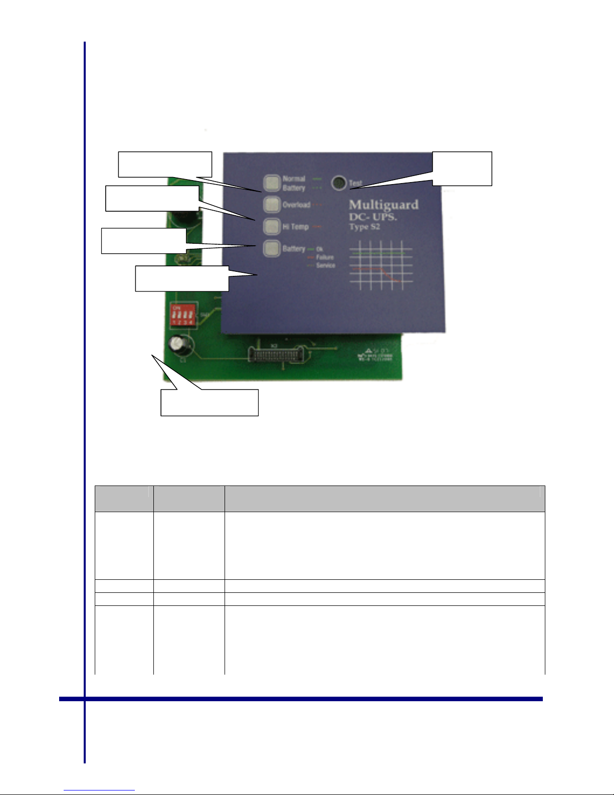
The UPS is equipped with a microcontroller for continually test of the Battery/Charger unit.
LED indicators in the front panel indicate status.
The following table describe the LED status for different conditions.
MULTIGUARD
DIP-switch pre setting:
DIP1: ON sets the sound alarm-buzzer ON.
DIP2: ON delay beeper 15min.
DIP3: ON delay beeper 30min.
DIP4: ON delay beeper 60min.
LED’s in the front panel indicate following:
LED’s Colour Description
LD4 Green Continually light when MAINS is OK.
When MAIN INPUT disappear, the LED will start flashing.
High battery voltage - 3 flashes, pause, 3 flashes pause ...
Medium battery voltage – 2 flashes, pause, 2 flashes, pause...
Low battery voltage– 1flash, pause, 1 flash, pause ...
LD3 Red Flash when over load
LD2 Red Flash when temperature in cabinet to high
LD1 Two-coloured
(red / green)
Battery status:
Green = Battery OK
Red = Batteryvoltage to low in the last test.
Red/green flashes = Battery OK, but more than 3 years old.
Flashes alternatively red/green during tests.
Flashes yellow during start-up.
Operational status Test-
button
Overload
Hi temperatur
Battery status
DIP-switch 1-4
2
Page 3

Service-mode
When pushing ”Test button” more than 10 sec., you enter “SERVICE MODE”.
In “SERVICE MODE” theTamper Switch is deactivated.
The 4 LED’s will flash and all other functions are disabled.
When service is completed and the cover is remounted, push the “Test button” more than 10 sec.
The control system will be reset.
Test routine
Starts automatically every 24 hours. The battery is disconnected and tested. LED flashing secquence
indicates battery status during the test. A green or red light will show the result of the test on the
battery status LED. The same test can also be started manually by pushing the “Test button” in the
front panel.
Start up
There is a 2 sec. delay to stabilize the power-supply and battery, when mains input is connected.
During “start up”, the BATTERY-LED will flash yellow.
3
MULTIGUARD
Page 4
Alarm conditions
When a fault condition occurs the alarm relay is activated, in addition to light and sound. With
DIP-switch 1 in OFF position all sound warnings will be deactivated. The alarm relay will stay
activated as long as one or more alarm conditions exist. Sound and LED light signals are
activated according to priority.
Priority example:
Mains power off, starts Alarm 2. If the cabinet door opens, Alarm 1 starts ( higher priority ).
When the door is closed, status goes back to Alarm 2. But if the mains input falls out whilst the
door is open , Alarm 2 will not occur until the door is closed.
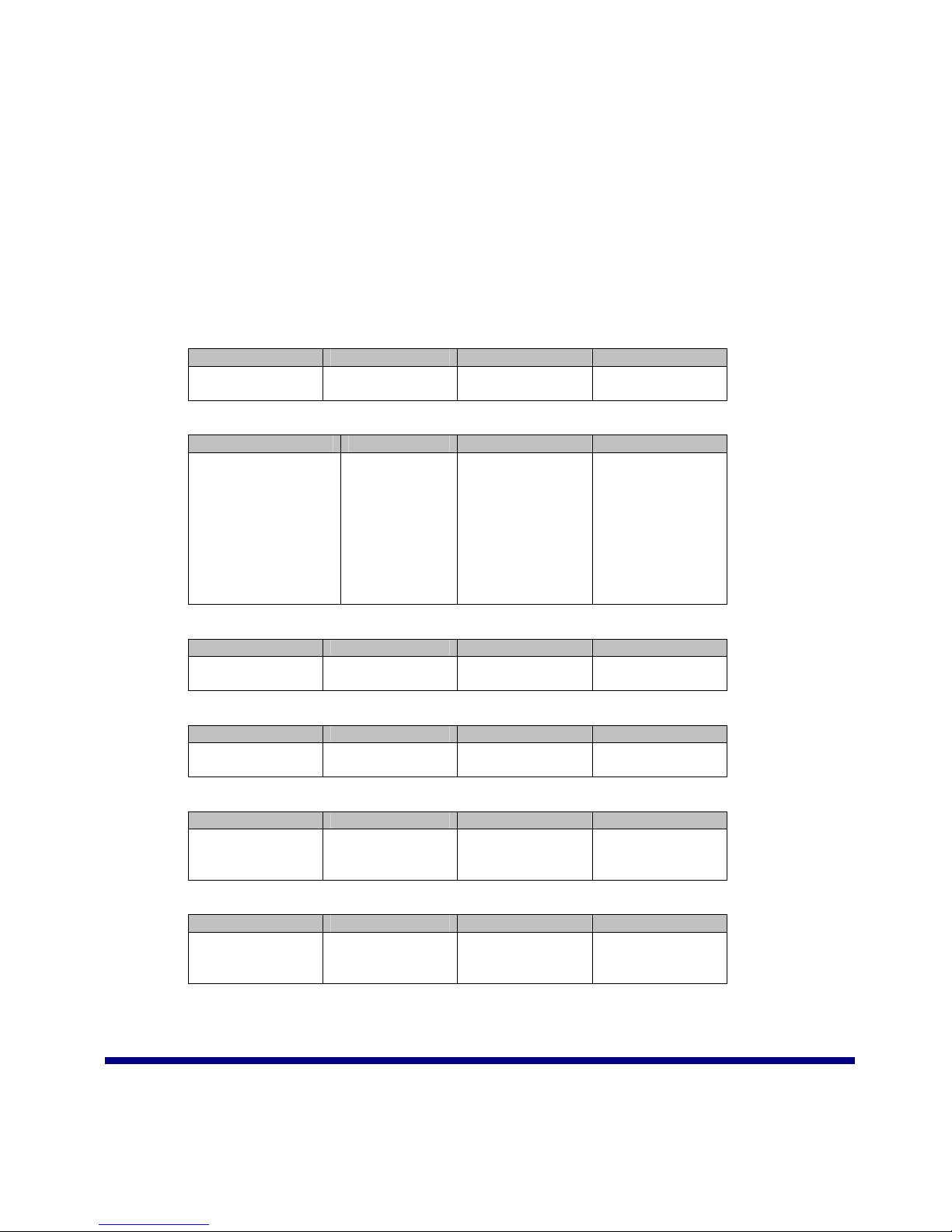
The following alarm conditions are listed according to priority:
Alarm 1
ON when Off when Light Sound
Door opens Door closed Only sound 7 beeps, pause, 7
beeps, pause, ...
Alarm 2
On when Off when Light Sound
Mains off.
Time delay for
alarm-relay DIPswitch:
- 0 min (All DIP off)
- 15 min (DIP 2)
- 30 min (DIP 3)
- 60 min (DIP 4)
Mains on Green LED
flashes. Pattern
depends on
battery voltage
6 beeps, pause, 6
beeps, pause, ...
Alarm 3
On when Off when Light Sound
Current overload
> 5A
Current under
limit
Overloaded LED
flashes
5 beeps, pause, 5
beeps, pause, ...
Alarm 4
On when Off when Light Sound
Temperature over
55 degrees
Temperaure
under 50 degees
Temperature LED
flashes
4 beeps, pause, 4
beeps, pause, ...
Alarm 5
On when Off when Light Sound
Battery voltage
too low (automatic
test)
Battery voltage
OK with manual
or automatic test
Battery status
LED, red
3 beeps, pause, 3
beeps, pause, ...
Alarm 6
On when Off when Light Sound
Battery more than
3 years old
Power-on reset Alternative red/
green battery
status -LED
2 beeps, pause, 2
beeps, pause, ...
MULTIGUARD
4
Page 5

Different ala
rm conditions give the following sound signals when DIP-switch 1 is set ON:
Condition activated Signal
Tamper (door open) 7 beeps, pause, 7 beeps, pause, ...
Power cut 6 beeps, pause, 6 beeps, pause, ...
Over load 5 beeps, pause, 5 beeps, pause, ...
Over temperatur 4 beeps, pause, 4 beeps, pause, ...
Battery fault 3 beeps, pause, 3 beeps, pause, ...
Battery to old 2 beeps, pause, 2 beeps, pause, ...
Battery ageing check
The monitoring system keeps track of the battery to check that it has been connected for more
than 1095 days ( 3 year ). When this time exceed, the battery status-LED will indicate time for
service.
5
MULTIGUARD
 Loading...