


CLASSIC II
QUATTRO
DECORATIVE FUEL EFFECT APPLIANCES FOR USE WITH
NATURAL GAS
IIN
INSTALLATION, SERVICING & USER
INSTRUCTIONS
THESE INSTRUCTIONS MUST BE LEFT WITH THE USER
MANUFACTURED BY:
MULTIGLOW FIRES
Canterbury Road, St. Nicholas-At- Wade.
Kent. CT7 0PQ
MULTIGLOW
FIRES

2
INDEX
SECTION 1. CONFORMITY AND GENERAL NOTES (INSTALLER)
SECTION 2. TECHNICAL DATA (INSTALLER)
SECTION 3. INSTALLATION PARAMETERS (INSTALLER)
SECTION 4. PRE-INSTALLATION CHECK (INSTALLER)
SECTION 5. INSTALLATION (INSTALLER)
SECTION 6. REMOTE CONTROL (INSTALLER & END USER)
SECTION 7. FUNCTION CHECKS & COMMISSIONING
(INSTALLER)
SECTION 8. FINAL CHECKS & CUSTOMER BRIEFING
(INSTALLER)
SECTION 9. SERVICING (SERVICE ENGINEER &END USER)
SECTION 10. END USER INSTRUCTIONS
SECTION 11. BURNER INSTALLATION RECORD AND
WARRANTY INFORMATION
MULTIGLOW
FIRES

3
PLEASE READ THESE INSTRUCTIONS FULLY
BEFORE COMMISSIONING OR USE
CONFORMITY & GENERAL NOTES
SECTION 1
Because Multiglow Fires believe in the use of modern technology and materials, they reserve the
rights to modify or change the layout and controls of their burner trays, at any time, whilst still
complying with current specifications.
Therefore these ‘Instructions’ are a general guide only and not specifically in compliance with the
shape or size of your appliance. These units must be installed in line with the current ‘GAS
SAFETY (INSTALLATION AND USE) REGULATION’ applicable to the country of use.
NOTE:
For the safe and efficient operation of this appliance, it must be installed inline with
the current British Standard (BS 5871:PART 3) or the equivalent standard for the country of use
and take into account the
Local and national building regulations or bylaws where necessary.
NOTE:
This appliance has been designed for use on NATURAL GAS only. Prior to
installation, ensure that the distribution conditions (identification of the type of gas and pressure)
and the adjustment of the appliance are compatible.
NOTE:
THE WHITE FIBRE BLANKET SHOULD NOT BE REMOVED FROM THE BURNER
TRAY.
NOTE:
Multiglow Fires will not accept any liability or responsibility for a appliance that has
been installed outside of the technical data specified in this manual and is not in agreement with
the above statements.
The MUTIGLOW CLASSIC II is a Decorative Fuel Effect (D.F.E.) primary aerated gas fire
designed to comply with BS EN 509:2000 and is intended for decorative use only. It has been
designed to operate on Natural Gas (N.G.) only and must be fitted on a non-combustible hearth in
a standard builders opening, with a class 1 chimney in compliance and satisfying the
requirements of BS 5871- PART 3. The appliance has been tested and approved with a flue of 7”
(178mm) diameter and having a minimum effective height of 10ft. (3mtrs.)
The MULTIGLOW CLASSIC II conforms to the relevant Safety Standards but during use there
are naked flames and parts of the casing become hot. A suitable guard to (BS.6539 fireguards for

4
use with solid fuel appliances) is therefore recommended where the young, elderly or infirm are
concerned.
NOTE:
The larger of the units manufactured have gas consumption similar to that of a small
boiler (i.e.50000 BTU). Therefore, it is essential that the gas supply pipe work be of a size that will
allow for the correct flow rate (See TECHNICAL DATA for required information). Ideally the 8mm
connection pipe to the burner should be as short as possible and the maximum length should not
be greater than 1mtr. Also ensure that the isolating tap does not have a reduced bore.
NOTE:
The Box used with this appliance will become hot during use. Care should be taken
when operating the controls.
SECTION 2
TECHNICAL DATA
GAS TYPE G20 at 20
mbar
CATEGORIES I2H
HEAT INPUT (GROSS kW )
6.95
FLOW RATE (m3/h)
0.65
WORKING ‘’P’’ (mbar)
20
BURNER TEST ‘’P’’(mbar)
9.3
REMOTE VALVE
GV60
PILOT OXY DEPLETION DEVICE
OP9039
ONE I NJECTOR
16/650
APPLIANCE MASS (kg)
6.0
DATA LABEL AFFIXED
TO BURNER TRAY
NOTE:
This size is rated below 7kw, therefore no vent is required if flue flow for the clearance
of the products of combustion is correct.
NOTE:
This appliance is to be used with a class 1 flue (7” diameter).
INSTALLATION PARAMETERS
SECTION 3 – REGULATIONS AND CODE OF PRACTICE
3.1 In your own interest and safety it is law that all gas appliances are installed by a
competent person, in accordance with the current Gas Safety (Installation and Use)

5
Regulations applicable to the country of use. In addition, the installation must be carried
out in-accordance with the relevant and current local and national specifications and
building regulations.
3.2 The fireplace surround, hearth and builders opening shall be of non-combustible material.
Hearth and clearance dimensions must comply with the requirements of BS 5071 part 3.
WARNING:This appliance must not be fitted in any room where steam is present (e.g.
bathroom).
3.3 The minimum clearance height above fireplace opening for a combustible shelf (having a
depth of 150mm (6”) is 200mm (8”), add 12mm (½”) for each additional 25mm (1”) depth
of shelf.
WARNING:Please note that soft wall coverings may become discoloured when close to a
heating appliance – this should be born in mind.
3.4 The minimum flue opening is 178mm (7”) diameter 250dq. Cm. (38½ sq. inches) and a
minimum effective height 3m (10ft). Provided that the flue, which is to serve this
appliance, satisfies the requirements of BS 5871:Part 3 then a terminal in-line fan
satisfying BS 5440: Part 1 may be used to improve flue draught.
WARNING: The flue must NOT be shared with any other appliance.
3.5 All chimney dampers or restrictions should be removed or permanently fixed in the open
position.
WARNING:If the fireplace has previously been used with a solid fuel the flue should be
swept clean prior to installation.
3.6 The room in which the appliance is to be fitted must have permanent air vent with a
minimum effective area of 100cm. Sq. (15½ sq. inches) and be accessible to the outside
air, unless specifically stated otherwise by the manufacturer.
NOTE:Vent should be checked on a regular basis to ensure that there is no obstruction.
PRE-INSTALLATION CHECK
SECTION 4
FLUE SOUNDNESS
4.1 Using a smoke bomb, carry out a flue flow test to check the effectiveness of the flue and
ensure that there is no leakage into another part of the premises (including any loft) or, as
appropriate, other adjoining premises.
NOTE:Although a smoke pellet produces a large amount of smoke, the volume is small
compared with the volume of the combustion products from an appliance. Clearance of
smoke from a pellet is, therefore, no guarantee that the products of combustion from the
appliance will clear. This must be tested after the installation is completed by carrying
out a spillage test
WARNING:Smoke coming out of other than the correct terminal, or a down-draught or
no-flow condition, indicates as unsatisfactory flue. The flue may need attention – seek
expert advice.
VENTILATION
4.2 In line with 3.7 above, make sure that the room or space where the appliance is located
is adequately ventilated and that the means of ventilation is suitable.

6
NOTE:The size and type of ventilation should take into account any other gas appliance
that may be fitted in the room or space
.
GAS SOUNDNESS
4.3
“An isolation valve, or valves, has to be fitted adjacent to the
appliance, which when closed allows the complete burner and
control assembly to be disconnected for
maintenance or repair in accordance with national regulations”
COMPATIBILITY
4.4Before commencing installation, check that the local distribution conditions (identification of
type of gas and pressure) and the adjustment of the appliance are compatible.
.
SECTION 5- INSTALLATION
A P PLIA N C E LO C ATIO N
The fire must be fitted on a flat non combustible base
Also a non combustible hearth or physical barrier
should be placed in front of the fire opening where
relevant.
This appliance is not fitted with an integral guard. In normal use
consideration may be given to the use of a fire guard, which conforms to
BS6539,such that accessibility to the naked flame produced by the
appliance is minimised.
It may not be desirable with a hole in the wall situation
to include a hearth with the appliance installation.
Building Regulation Approved Document J currently
states:-
A Appliances should be placed on a hearth unless:
They are installed so that every part of any flame
or incandescent material will be at least 225mm
Above the floor
Or
B. The manufacturers instructions state that a
Hearth is not required
Multiglow Fires recommend that a hearth or
physical barrier is installed with this appliance
7
However should you decide not to follow the
recommendation and do not fit a hearth or
barrier or decide to remove one or both.
Then consideration as to the safety of the
occupants of the room should be given.
CONTENTS CHECKLIST
1. Box
2. Four Part Frame (attached to box)
3. Fixing Screws
4. Burner Shelf
5. Burner
6. Refractories
7. 1 x Receiver pack (Inc batteries)
8. 1x Burner Control Unit
9. 1x Nut and Olive for 8mm Inlet Pipe
1x 1½ meter 8mm Copper Pipe
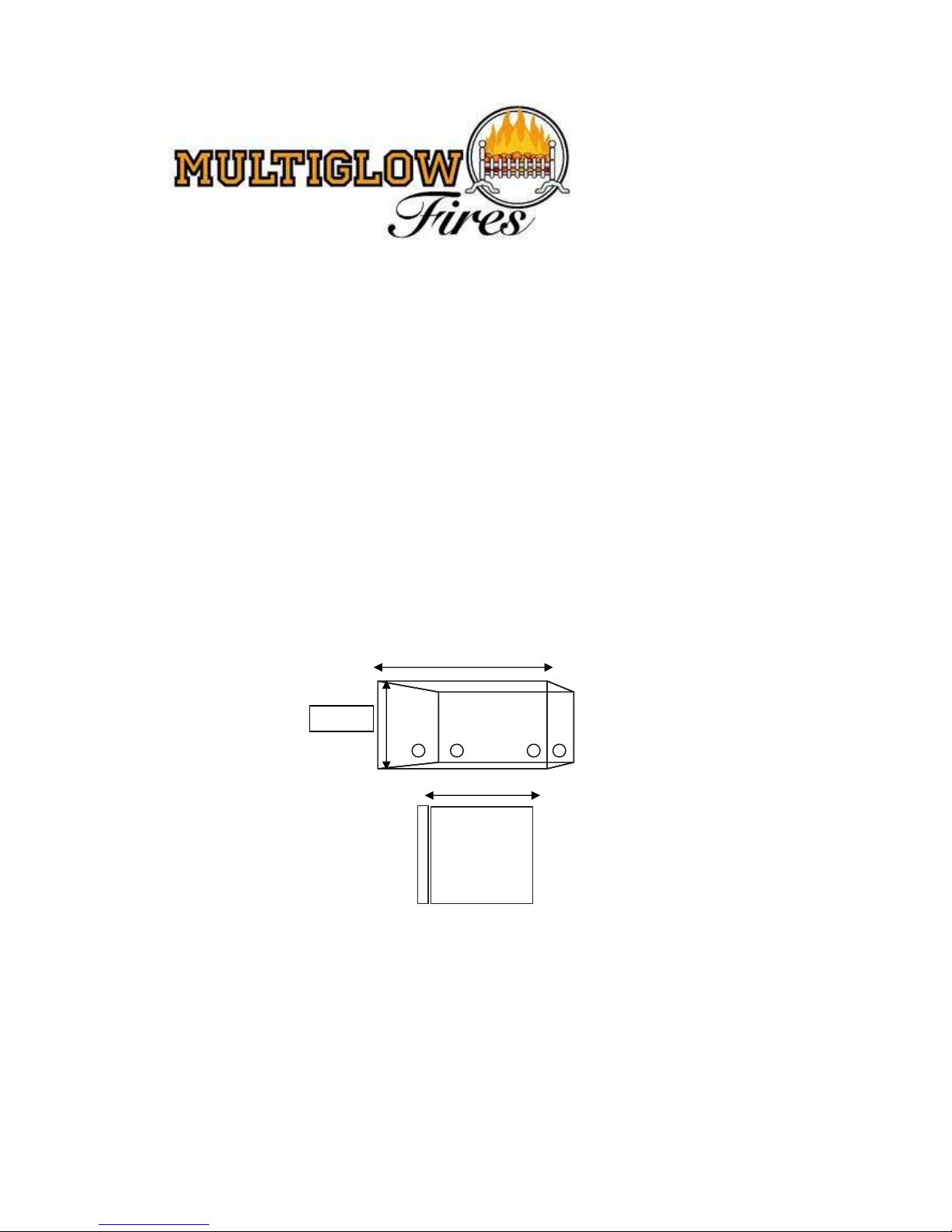
Preparing the Fireplace Opening
1. Create an opening for the box using
the dimensions shown.
2. Shown are the actual box dimensions when creating
the hole for the box allow 2-5mm extra for a good fit.
600mm
330mm
3. The base of the opening must be flat and level.
4. Route the gas supply feed inside the fireplace
opening and provision made for it to enter the
box through one of the four slots either at the
back of the box or at either side.
5.Remove the four pieces of frame by unscrewing
the screws, see next page.
400m
8
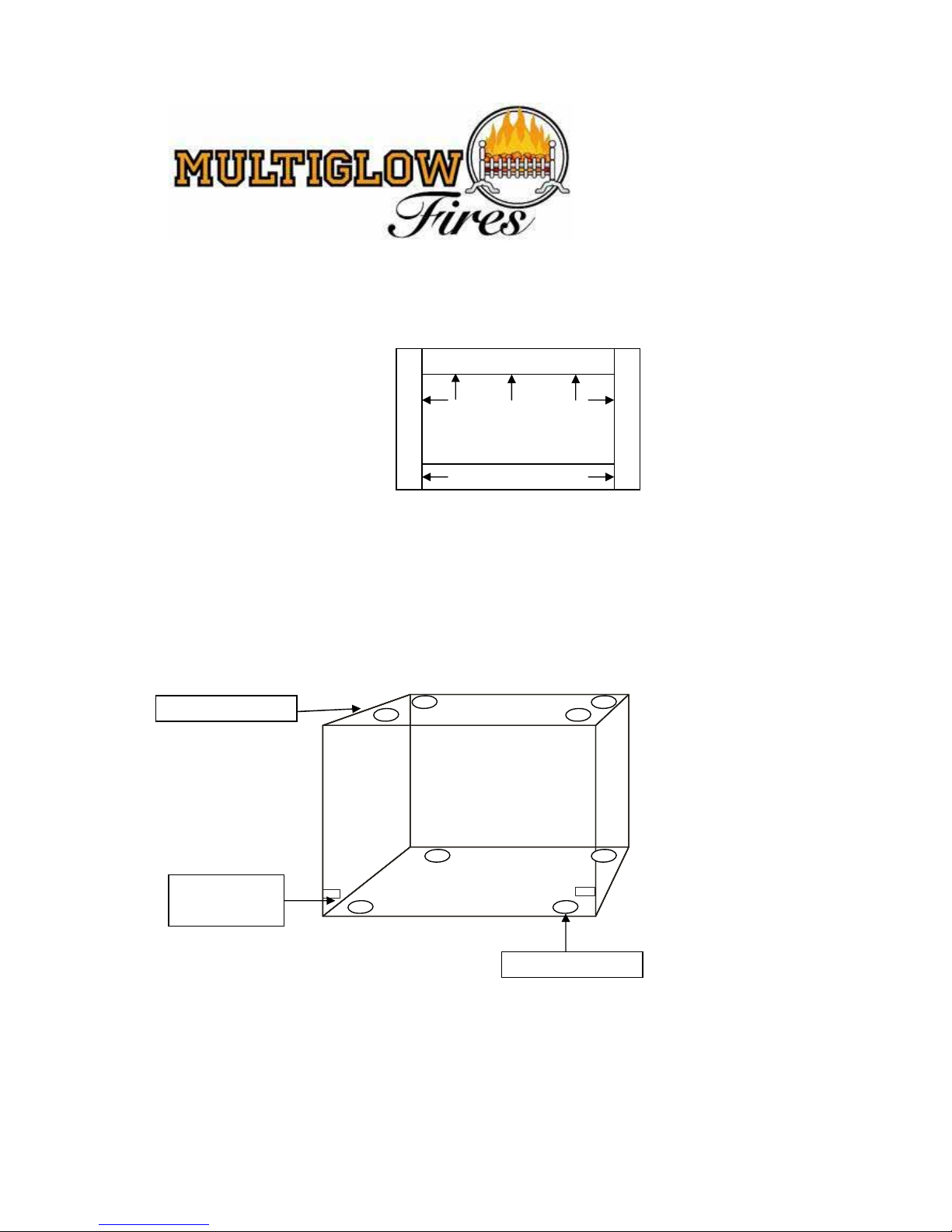
6. Place the box centrally into the opening.
7. Whilst holding the box in place, mark
the appropriate holes in the base and
roof of the box.
8. Remove the box, drill and plug the respective
positions.
9. Replace box and fix with screws supplied.
10. Place burner shelf in the box sliding front
legs onto locating pins.
11. Prepare the gas supply pipe for final fixing
12. Fit burner in burner shelf.
13. Fit the four piece frame back onto the box
ensuring the bottom flap opens and closes without
LOCATING
PIN
FIXING HOLES
FIXING HOLES

9
too much force.
14. Purge the gas supply pipe work to remove air and debris BEFORE connection of the fire.
The 8mm pipe should be used to connect valve to an isolating tap, which must be
adjacent to the appliance (so that when tap is closed appliance is totally isolated). NOTE
Soft soldered joints should not be used beneath the burner tray.
WARNING: Flexible pipe must not be used .
15. Turn on gas supply and check for gas soundness. (Tests should be carried out in
accordance with current Gas Safety Regulations).
16. Place refractories on burner as shown
PEBBLE AND DRIFTWOOD LAYOUT
TOTAL = 16 PEBBLES, 1 LARGE, 1 MED LARGE, 8 MED OF DRIFTWOOD
UNDER NO CIRCUMSTANCES MUST YOU CHANGE THE
THE LAYOUT OR QUANTITY OF REFRACTORIES
LAYER 1 LAYER 2
1 X LARGE PIECE OF DRIFTWOOD 1 X MED/LARGE PIECE OF
3 X ROW OF 6 PEBBLES DRIFTWOOD
LAYER 3 LAYER 4
4 X MED PIECES OF DRIFTWOOD 4 X MED PIECES OF DRIFTWOOD
1 X SMALL PIECE OF DRIFTWOOD

10

11

12

13

14

15

16

17

18

19

20
Check that the valve and remote control are all functioning properly. If there is a problem
double check the trouble shooting guide in section 6.
REFERENCE PRESSURE
7.0 The appliance is pre-set to the given heat input for the inlet pressure given on the
Data Plate. No further adjustment should be necessary. However, the burner can be
checked by fitting a pressure gauge at the Test Point accessible to the left of the Control
Valve. The pressure should be checked with the appliance alight and the control set at
‘High’. After checking pressure, turn off appliance, remove Pressure Gauge, replace Test
Point Seal and check gas soundness.
CHECK FOR SPILLAGE
IMPORTANT: A SPILLAGE CHECK MUST BE MADE BEFORE THE INSTALLED
APPLIANCE IS HANDED OVER TO THE CUSTOMER.
This test is to be carried out with the appliance fully fitted and front flap in position.
Close all doors and windows of the room in which the appliance is fitted.
Light the fire and set the control to maximum and leave for five (5) minutes.
After five (5) minutes, light a smoke match and position flush with fireplace opening, a minimum
of 50mm (2”) from side and a maximum of 50mm (2”) from top.
The installation is satisfactory if the smoke is drawn into the chimney and out of the room.
If this does not happen then leave alight for a further ten (10) minutes and check again.
WARNING:If smoke is still not drawn up the chimney, turn off and disconnect the
appliance and seek expert advice.
WARNING:If the fire goes out under normal operation and continues to go out after
relighting, spillage has occurred and the flue should be checked.
This appliance is fitted with a pre-set Oxygen Depletion System incorporated into the Pilot Ignition
Unit. Therefore this system must not be adjusted or put out of operation and must be replaced
with a complete unit of original manufacture in the event of renewal.
SECTION 8. FINAL CHECK & CUSTOMER BRIEFING
8.0 Instruct the customer on the full operation of the appliance.
8.1 Recommend to the customer that a competent person should service the appliance annually.
8.2 Recommend to the customer that on a yearly basis the flue should be swept and that rubbish
should not be thrown or burnt on the fire or fuel bed disturbed.
SECTION 7. FUNCTION CHECKS &
COMMISSIONING

21
8.3 Instruct the customer that the pilot and flame-sensing device fitted to this fire also acts as an
atmospheric sensing device, which shuts off the appliance if the evacuation of the products of
the combustion is interrupted.
If the fire shuts off, restart the main burner as stated in section 6. If the appliance fails to
relight or repeatedly cuts off, then do not use and inform a qualified person.
8.4 Inform customer of end users instructions Sections 10& 11 of this manual.
8.5 Hand over these User instructions to the customer.
SECTION 9. SERVICING
SPARES LIST
FIG. N
O.
DESCRIPTION
PART No.
QTY.
1
PILOT BURNER & IGNITION UNIT
9039
1
SEC 6
CONTROL VALVE
GV 60
1
SEC 6
RECEIVER PACK
G6R PISOA5AS10
1
SEC 6
4 X AA ALKALINE BATTERIES 1 X 9 VOLT BATTERY
ENERGIZER
4, 1
Fig 1.
All servicing of this appliance is to be carried out by a competent person.

22
Turn off gas supply before commencing any servicing. Always check for gas soundness and
spillage after refitting the appliance.
9.1 GENERAL MAINTENANCE
At yearly intervals, turn off and allow to cool down. Check all refractories, pilot
burner/ignition unit, for soot or debris deposits. Theses can cause imperfect flame
appearance and should be removed by brushing with a soft brush (DO NOT USE A
VACUUM CLEANER). Replace all misplaced pebbles/driftwood as per layout (see page
9) and relight.
NOTE:On the failure of either the pilot burner/ignition unit, or main control valve, have
repairs carried out by a competent person.
9.2 RENEWING PILOT BURNER/IGNITION UNIT (Fig.1)
9.2.1 Isolate gas supply.
9.2.2 Remove all refractories– store in a safe place.
9.2.3 Disconnect main 8mm gas supply pipe from control valve (See section 6)
9.2.4 Remove appliance from tray.
9.2.5 Undo and remove thermocouple nut from the rear of the control valve.
9.2.6 Disconnect and remove piezo ignition wiring from ignition electrode (Fig.1 (2))
9.2.7 Undo and remove the 4mm
gas
supply pipe from the bottom of the pilot burner (Fig.1 (5) )
9.2.8 Undo and remove 2x 4mm locating nuts/screws on pilot/ignition unit. Remove unit.
9.2.9 Replace with a new unit and reassemble in reverse order.
10.0 For safe operation of this appliance which includes lighting and shut-down procedures,
including instructions in the event of remote breakdown (manual ignition) please refer to
section 6 of this manual.
10.1 The chimney shall be swept regularly to ensure that all products of combustion
are entering the flue, and that there is no excessive build up of soot.
10.2 Any debris from any source or any soot shall require removal; this must be done
by using a soft brush (DO NOT USE A VACUUM CLEANER).
10.3 THE USER IS WARNED NOT TO THROW RUBBISH ON OR OTHERWISE
DISTURB THE FUEL BED.
10.4 WHERE IT IS NECESSARY TO REMOVE THE REFRACTORIES FOR
CLEANING PURPOSES,THIS MUST BE DONE USING A SOFT BRUSH (DO NOT
USE A VACUUM CLEANER).WHEN REPLACING THE REFRACTORIES THIS
MUST BE DONE AS PER LAYOUT SHOWN ON NEXT PAGE,UNDER NO
CICUMSTANCES SHOULD THE LAYOUT BE CHANGED OR MORE
REFRACTORIES ADDED OR TAKEN OFF.
SECTION 10. END USER
INSTRUCTIONS

23
FIG 1, LAYER 1 FIG 2, LAYER 2
1 X LARGE PIECE OF DRIFTWOOD 1 X MED/LARGE PIECE OF
3 X ROW OF 6 PEBBLES DRIFTWOOD
FIG 3, LAYER 3 FIG 4, LAYER 4
4 X MED PIECES OF DRIFTWOOD 4 X MED PIECES OF DRIFTWOOD
1 X SMALL PIECE OF DRIFTWOOD
FIG 1
FIG 3
FIG 4
FIG 2

24
PLEASE FILL IN INFORMATION BELOW FOR FUTURE REFERENCE INFORMATION CAN BE FOUND ON THE DATA PLATE
SERIAL NO
WARRANTY INFORMATION
If within the period of one year of purchase there is the unlikely
occurrence of defect in either materials or workmanship Multiglow
will arrange to repair or replace the item free of charge.
All warranty claims must be made through the retailer that this appliance
was purchased through.
Multiglow are not able to discuss with the purchaser any claim until
the retailer has inspected a claim and deemed it valid this being due
to the fact that the purchaser's contract of sale is with the retailer.
When a defect is due to installation error or misuse Multiglow reserve the
right to refuse service or make the appropriate charge for any warranty
call.
DATE
MODEL
MODEL
SERIAL NUMBER
INSTALLER
INSTALLATION DATE

25
 Loading...