

Installation, Servicing & User Instructions
THESE INSTRUCTIONS TO BE LEFT WITH THE USER
Manufactured By:
Multiglow Fires
Canterbury Road,
St. Nicholas-at-Wade,
Nr. Canterbury,
Kent CT7 0PQ
Telephone: 01843 847575
Fax: 01843 848300
Email: sales@multiglow.com
Web: www.multiglow.com
IM002.2 (20thMay 2010)
Classic II LPG
Decorative fuel effect appliances
for use with Liquified Petroleum Gas

Copyright:
This manual is copyrighted by Multiglow Fires © 2010.
No part of this document may be reproduced in any form or by any means, without the
express written permission of Multiglow Fires.
Warranty:
Multiglow Fires takes pride in using and supplying high quality materials and parts.
However, should any defect in either the workmanship or the materials used become
apparent within one year of purchase, Multiglow Fires will replace or repair the item, free
of charge, at a time that is convenient to you, our valued customer.
In order to ensure your safety, warranty claims must be made through the retailer from
whom the product was purchased.
Under UK law, the purchaser’s contract of sale is with the retailer. As such, Multiglow Fires
cannot enter into discussions with the purchaser until the retailer has inspected any
claim and validated it.
Multiglow Fires reserve the right to make a charge for any service call or to refuse service
when a defect is due to incorrect use or installation.

Page i
Table of Contents
GENERAL INFORMATION .......................................................................................1
1. Conformity.................................................................................................... 2
2. General Notes............................................................................................... 3
2.1. Flue Specifications.................................................................................... 4
2.2. Ventilation Requirements.......................................................................... 4
3. Technical Data .............................................................................................. 5
INSTALLATION INSTRUCTIONS.............................................................................6
4. Installation Procedure.................................................................................... 7
4.1. Contents Checklist.................................................................................... 7
4.2. Compatibility............................................................................................ 7
4.3. Installation (Hole in the Wall).................................................................... 9
4.3.1. Ventilation.......................................................................................... 9
4.4. Pre-Installation Checks ............................................................................10
4.4.1. Flue soundness..................................................................................10
4.4.2. Ventilation.........................................................................................11
4.4.3. Gas Soundness ..................................................................................11
4.4.4. Ignition Check ...................................................................................11
4.5. Burner Installation...................................................................................11
4.5.1. Baskets and Cast Inserts.....................................................................12
4.5.2. Standard Inserts (Burners with Legs)...................................................12
4.6. Connection to Gas Supply ........................................................................13
4.7. Gas Control Installation............................................................................13
4.7.1. Remote Control (GV34).......................................................................13
4.7.2. Remote Control (GV60).......................................................................14
4.7.3. Wall Switch Control (GV60).................................................................15
4.8. Fuel Bed Installation................................................................................16
5. Function Checks...........................................................................................17
5.1. Lighting the Pilot and Main Burner............................................................17
5.2. Checking the Reference Pressure..............................................................17
5.3. Checking for Spillage...............................................................................17
6. Commissioning.............................................................................................18
7. Final Check & Customer Briefing....................................................................19
8. Servicing .....................................................................................................20
8.1. Parts List................................................................................................20
8.2. General Maintenance...............................................................................20
8.3. Renewing Pilot Burner/Ignition Unit ..........................................................20
8.4. Renewing Control Valve...........................................................................22
USER INSTRUCTIONS...........................................................................................23
9. Fuel Bed Layouts..........................................................................................24
9.1. Pumice Pellets.........................................................................................24
9.2. Coal Layout ............................................................................................24
9.2.1. Size ‘T’ (6.50kW)................................................................................24

Page ii
9.3. Pebble Layout.........................................................................................25
9.3.1. Size ‘T’..............................................................................................25
10. Control Systems ...........................................................................................26
10.1. Identification ..........................................................................................26
10.2. Manual Control (Barrel)............................................................................27
10.3. Manual Control (BM) & Detached Manual Control (BM)...............................28
10.4. Remote Control (GV34)............................................................................29
10.4.1. Manual Lighting Procedure..................................................................29
10.4.2. Remote Control Lighting Procedure......................................................30
10.4.3. Shut Off Procedure.............................................................................30
10.5. Remote Control (GV60)............................................................................31
10.6. Wall Switch Control (GV60)......................................................................32
10.7. Remote Control Handset Battery Replacement...........................................32
10.8. Remote Control Receiver Unit Battery Replacement....................................32
TROUBLESHOOTING.............................................................................................34
11. General Troubleshooting...............................................................................35
12. Appendix 1 – GV60 Installation Instruction .....................................................36

Page 1
GENERAL INFORMATION
Page 2
1. Conformity
Because Multiglow Fires believe in the use of modern technology and materials, they
reserve the rights to modify or change the layout and controls of their burner trays, at
anytime, whilst still complying with current specifications.
Therefore these ‘instructions’ are a general guide only and are not specifically in
compliance with the shape or size of your appliance. These units must be installed in line
with current ‘GAS SAFETY (INSTALLATION AND USE) REGULATION’ applicable to the
country of use.
Warning
Only use the approved refractories supplied with this appliance.
NOTE: For the safe and efficient operation of this appliance, it must be installed inline
with current British Standard (BS 5871: PART 3) or the equivalent standard for
the country of use and take into account the local and national building
regulations or bye-laws where necessary.
NOTE: This appliance has been designed for use with LPG only. Prior to installation,
ensure that the distribution conditions (identification of the type of gas and
pressure) and the adjustment of the appliance are compatible.
NOTE: The fire must not be operated with either the white fibre blanket, pumice or black
ceramic board (dependent upon model) removed from the burner tray.
NOTE: Multiglow Fires will NOT accept any liability or responsibility for an appliance that
has been installed outside the technical data specified in this manual and is not in
agreement with the above statements.

Page 3
2. General Notes
The MULTIGLOW CLASSIC II LPG is a Decorative Fuel Effect (D.F.E.) primary aerated
gas fire, designed to comply with BS EN 509:2000 and is intended for decorative use only.
It has been designed to operate on LPG Gas only and must be fitted on a non-combustible
hearth in a standard builders opening, with either a Class 1 (7”) or Class 2 (5”)
chimney/flue (subject to appliance size) and satisfy the ventilation requirements of BS 5871
– Part 3.
This appliance conforms to the relevant Safety Standards but during use, there are naked
flames and parts of the casing become hot.
Warning
If the appliance is fitted with a permanent guard (to BS 6778), no part of
the guard should be permanently removed so that access to the flame is
minimized, as it does not give full protection for young children, the
elderly or the infirm.
This appliance is not fitted with an integral guard. In normal use
consideration may be given to the use of a guard conforming to BS 6678
or BS 6539 such that the access to the flame is minimised and for the
protection of young children, the elderly or the infirm.
NOTE: The larger of the units manufactured have gas consumption similar to that of a
small boiler (i.e. 50,000 BTU). Therefore, it is essential that the gas supply
pipework be of a size that will allow for the correct flow rate (see TECHNICAL
DATA for required information). Ideally, the 8mm connection pipe to the burner
should be as short as possible and the maximum length should not be greater
than 1m. Also ensure that the isolating tap does not have a reduced bore.
NOTE: The Basket or Fret used with this appliance will become hot during use. Care
should be taken when operating the controls.
RCF Advice:
This product may use components containing Refractory Ceramic Fibres (RCF), which are
main-made vitreous silicate fibres. Excessive exposure to the fine dust of this material
may cause irritation to eyes, skin and respiratory tract.
Therefore during installation and servicing we recommend that you use a HEPA filtered
vacuum cleaner to remove any dust and soot accumulated in and around the fire before
and after working on the fire, to ensure that the release of fibres from these RCF articles is
kept to a minimum.
You should follow the normal hygiene rules of not smoking, eating or drinking in the work
area.
When replacing components containing Refractory Ceramic Fibres (RCF), we recommend
that the replaced items are not broken up, but are sealed within heavy duty polythene

Page 4
bags, clearly labelled as RCF waste and may be disposed of in suitably licensed landfill
sites.
It should be noted that exposure to the fibres is unlikely in normal use.
2.1. Flue Specifications
All appliance sizes have been tested and approved with a flue of 7” (178mm) diameter and
having a minimum effective height of 10ft (3m).
2.2. Ventilation Requirements
The room in which the appliance is to be fitted must have permanent air vent with
a minimum effective area of 100 sq. cm (15
1/2
sq. inches) and be accessible to
the outside air.
All ventilation must comply with the rules in force for the country in which
the appliance is fitted.
NOTE: Vent should be checked on a regular basis to ensure that there is no obstruction.
Warning
An extractor fan must not be fitted in the room that the ventilation is
taken from.
Page 5
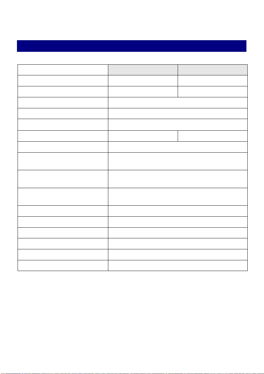
3. Technical Data
Size
T
T
Gas Category
I3+I
3B/P
Gas Types
G30/G31
G30
Surface Area (cm2)
451/650
Heat Input (Gross kW)
6.5
Flow Rate
(m3/h
)
0.176
Working “P” (mbar)
28-30/37
30
Burner Test “P” (mbar)
28.0
Control Valve
(Manual Option)
Seagas A5
Control Valve
(Remote Option)
GV34 or GV60
Control Valve
(Wall Control Option)
GV60
Valve
Seagas A5
OxyPilot (SIT)
9205
Injector (1 per appliance)
10/180
Gas Connection Size
8mm
Appliance Mass
12.5kg
Data Label
Affixed to burner tray

Page 6
INSTALLATION INSTRUCTIONS

Page 7
4. Installation Procedure
4.1. Contents Checklist
1 x Installation, Servicing & Users instructions.
1 x Burner (with fibre blanket, ceramic board or pumice pellets).
1 x Nut and olive for 8mm inlet pipe.
Coals/Logs/Pebbles (if supplied).
Pack of Pumice Pellets (if supplied).
Additional Parts Supplied with Detached BM Control model:
1 x Valve Mounted Bracket.
1 x Detached BM Control Valve (with 850mm long piezo lead).
1 x P4-22D Co-pilot (with 1 metre long thermocouple lead).
1 x M4 x 10mm Valve locating screw.
1 x 1 metre 8mm Copper Pipe.
1 x 1 metre 4mm Copper Pipe.
Additional Parts Supplied with Remote Control (GV34 & GV60) models:
1 x Remote Control handset.
1 x Remote Control Receiver (connected to burner).
1 x 9v battery (for handset).
4 x AA batteries (for battery operated receiver only).
1 x Mains transformer (for mains operated receiver only).
1 x wall switch (optional for GV60 full sequence models).
1 x Heat shield (if supplied).
4.2. Compatibility
Before commencing installation check that the local distribution conditions (identification of
type of gas and pressure) and the adjustment of the appliance are compatible.
1) In your own interest and safety it is law that all gas appliances are installed by a
competent person, in accordance with the current Gas Safety (Installation and Use)
Regulations applicable in the country of use. In addition, the installation must be
carried out in accordance with the relevant and current local and national
specifications and building regulations.
2)
The fireplace surround, hearth and builders opening shall be of non – combustible
material. Hearth and Clearance dimensions must comply with the requirements of BS
5071:PART 3
Page 8
Warning
This appliance must not be fitted in any room where steam is present (e.g.
Bathroom)
3)
The appliance must be mounted behind a non-combustible hearth and be 50mm (2”)
above floor level to discourage the over-laying of carpets or rugs etc.
4)
There must be a 125mm (5”) clearance underneath the appliance if it uses either a
GV34 or GV60 valve unless using the heat shield supplied.
5) The minimum clearance height above fireplace opening for a combustible shelf
(having a depth of 150mm (6”) is 200mm (8”); add 12mm (1/2”) for each additional
25mm (1”) depth of shelf.
Warning
Please note that the soft wall coverings may be come discoloured when
close to a heating appliance – this should be born in mind.
6) When installed into a Class 2 flue system, the minimum flue opening for
appliance models A and B is 125mm (5”).
7)
When installing into a Class 1 chimney, the minimum flue opening is 178mm (7”)
diameter 250cm2 (38½ sq. inches) and a minimum effective height 3m (10ft).
Provided that the flue which is to serve this appliance satisfies the requirements of BS
5871:PART 3 then the terminal in-line fan satisfying BS5440:PART 1 may be used to
improve flue draught.
Warning
The flue must NOT be shared with any other appliance.
8) All chimney dampers or restrictions should be removed or permanently fixed in the
open position.
Warning
If the fireplace has previously been used with solid fuel the flue should be
swept clean prior to installation and a flue test in accordance with national
regulations is carried out.
9) The room in which the appliance is to be fitted must have permanent air vent with a
minimum effective area of 100cm2 (15½ sq. inches) and be accessible to the outside
air, unless specifically stated otherwise by the manufacturer.
NOTE: Vent should be checked on a regular basis to ensure that there is no obstruction.
Page 9
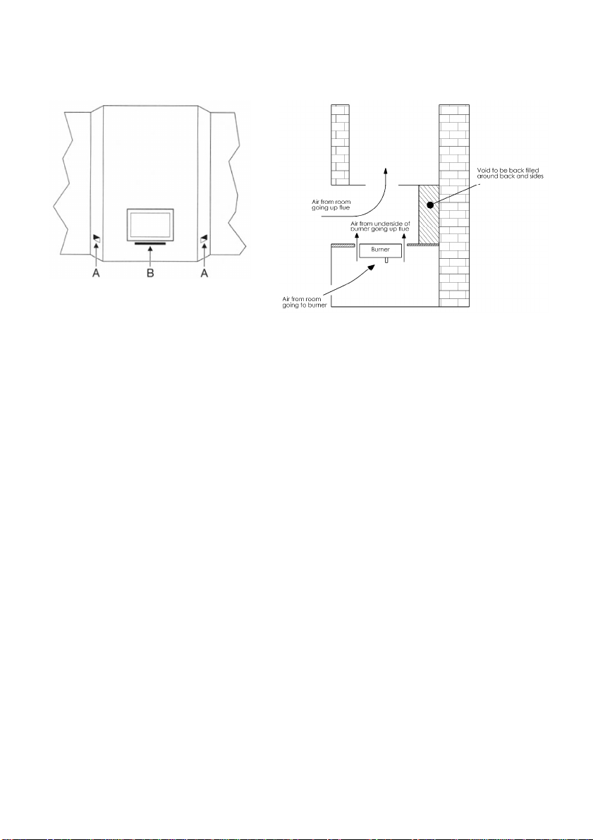
4.3. Installation (Hole in the Wall)
Figure 1
Figure 2 – Correct Air Flow
4.3.1. Ventilation
When installing a raised chamber fire, it is critical to ensure that the ventilation for the fire
(for combustion and cooling purposes) is carefully thought through. Failure to provide
suitable ventilation may invalidate your warranty.
For Cooling Purposes
The requirement is that air is drawn from the room into the cavity below the burner and
up through the vents at the back of the chamber, then up the flue. This will keep the
control equipment below 700c – the manufacturer’s recommendation.
Refer to the diagrams above, which identify where the ventilation holes may be located. It
is recommended that location “A” is chosen for aesthetic reasons. A proprietary grille
should be used. The ventilation must be at least 100cm2 free area in total.
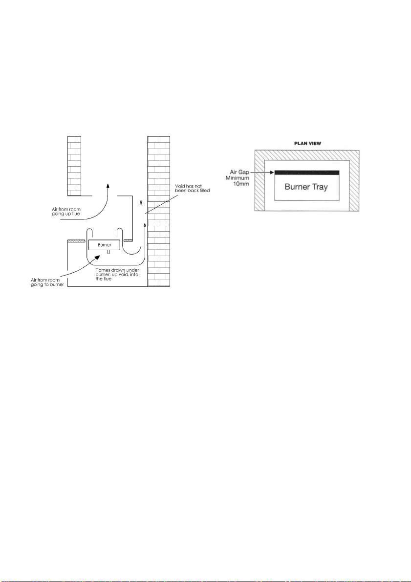
In all cases it is essential that the void shown in Figure 2 above is sealed as shown.
For Combustion Purposes
The requirement is that air is drawn into the chamber from the room and then up the flue.
1) Decide where the gas supply will feed to and from.
2) Decide where the steel chamber will sit. If any incandescent materials are at least
225mm above the floor, a hearth may not be required (but refer to the next point
below).
3)
However, Building Regulation Document J, paragraph 3.40 currently states:
An appliance shall be placed on a hearth unless:
Page 10
a) They are installed so that every part of any flame or incandescent material will be
at least 225mm above the floor; or
b)
The manufacturer’s instructions state that a hearth is not required.
It is Multiglow’s recommendation that a hearth is used with this appliance. Should
you decide that a hearth is not required, then consideration should be given to the
safety of the users of the room.
Figure 3 – Incorrect Air Flow
Figure 4
4.4. Pre-Installation Checks
4.4.1. Flue soundness
Using a smoke bomb, carry out a flue test to check the effectiveness of the flue and
ensure that there is no leakage into another part of the premises (including any loft) or, as
appropriate other adjoining premises.
NOTE: Although a smoke pellet produces a large amount of smoke the volume is small
compared with the combustion products from an appliance. Clearance of smoke
from a pellet is therefore no guarantee that the products of combustion from the
appliance will clear. This must be tested after the installation is completed by
carrying out a spillage test.

Page 11
Warning
Smoke escaping anywhere other than the correct terminal, or a downdraught or no-flow condition indicates an unsatisfactory flue. The flue
may need attention - seek expert advice.
4.4.2. Ventilation
In line with Section 2.2 - Ventilation Requirements, make sure that the room or
space where the appliance is located is adequately ventilated and that the means of
ventilation is suitable.
NOTE: The size and type of ventilation should take into account any other gas appliance
that maybe fitted in the room or space.
4.4.3. Gas Soundness
It is a requirement that an isolation valve or valves are fitted adjacent to the appliance
which when closed allows gas soundness checks to be carried out on the installation pipe
work and also allows the complete burner and control assembly to be disconnected for
maintenance or repair in accordance with national regulations.
NOTE: Check that an adequate size gas isolation valve is fitted and working.
4.4.4. Ignition Check
The pilot and ignition unit is mounted to the front and centre of the main burner unit.
Check by observation that a spark is produced between the pilot thermocouple/burner
head and the piezo electrode by using the lighting procedure, defined in Section 10 -
Control Systems.
4.5. Burner Installation
1) The fire should be fitted under the flue opening so that no part of the fire bed
protrudes beyond the fireplace opening. If your appliance is fitted with legs it is a free
standing type and is to be secured to the hearth or fireplace floor.
2) Place appliance centrally into fire opening so that the back of the burner tray is a
MINIMUM of 10mm from the rear wall of the fireback insert.
3) For Remote control and Wall switch control models, fold and mount the heat
shield (where supplied/required) in an appropriate place, underneath or adjacent to
the burner.
4) For Wall switch control models, the wall switch may be fitted into an appropriately
sized flush or surface mounted box. Wiring may then be run to where the receiver
unit is to be mounted.
5) For Mains operated receiver models locate the transformer in a suitable position
(this must not be under the fire) where it can be wired into the mains electric supply

Page 12
and the low voltage lead connected to the receiver. Transformers must be connected
to the mains supply in accordance to the rules in force.
6) Before securing the burner into position, run the gas pipe as appropriate.
7) Dependent upon the application, use one of the following methods to make provision
for burner fixings.
4.5.1. Baskets and Cast Inserts
The burner tray must be appropriately secured into either the basket or cast insert, so that
it cannot move during operation.
NOTE: If appliance is to be used in conjunction with a free standing basket, place burner
tray into basket and secure with fixing provided then position both burner tray
and basket centrally into the hearth opening.
4.5.2. Standard Inserts (Burners with Legs)
If using a proprietary flue box, burner fixings may be provided. Alternatively, proceed as
follows:
1) Mark the hearth floor through the fixing holes provided in appliance mounting legs.
2) Remove the appliance and using a suitable masonry drill, drill marked positions and fit
suitable rawlplugs.
3) Replace and realign the appliance and/or secure into position with suitable screws.

Page 13
4.6. Connection to Gas Supply
1) Purge the gas supply pipe work to remove air and debris BEFORE connection of the
fire. The 8mm pipe should be used to connect valve to an isolating tap, which must
be adjacent to the appliance (so that when tap is closed appliance is totally isolated).
NOTE: Soft soldered joints should not be used beneath burner tray.
Warning
Flexible pipe must not be used.
2) Turn on the gas supply and check for gas soundness (tests should be carried out in
accordance with current Gas Safety Regulations).
4.7. Gas Control Installation
The following procedures describe additional work required depending upon the specific
control method supplied with the appliance.
4.7.1. Remote Control (GV34)
Figure 5

Page 14
1) Connect the 800mm lead provided between the motor connections on the Control
Valve and the Receiver.
2) Insert 4 x 1.5v AA alkaline batteries into the receiver.
3) Place the receiver unit into position (within heat shield if used).
4) Insert and connect 1 x 9v alkaline battery into the handset.
Warning
The free air circulation below the burner must be such that the
temperature of any electrical or electronic component does not exceed 60
0
centigrade.
NOTE: In line with the best engineering codes and practices, it is essential that the
electrical wiring is protected from accidental damage. It is advised that the
flexible cables are placed in a plastic tube or sheath especially where the wiring
must pass through a wall or behind a fireplace surround. All wiring situated
below the burner should be placed so that the maximum clearance is obtained
from any potential hotspots.
NOTE: The Receiver can be fixed to the floor beneath the appliance, so long as there is
adequate ventilation and no interference to the Handset signal.
4.7.2. Remote Control (GV60)
1) The GV60 remote control comes pre-wired. When installing make sure that the
ignition cable and infra-red sensor cable are kept apart by a minimum of 20mm.
2) If using battery operated receiver: Insert 4 x 1.5v AA high quality Alkaline,
Lithium or Nickel oxy hydroxide batteries into the receiver.
3) If using mains operated receiver: Ensure that there are no batteries in the
receiver unit, and then connect the transformer lead into the power inlet socket of the
receiver.
Warning
Using the mains transformer whilst batteries are installed in the receiver
unit may cause damage to both the batteries and the receiver.
4) Place the receiver unit into position (within heat shield if used).
5) Insert and connect 1 x 9v alkaline battery into the handset.
Warning
The free air circulation below the burner must be such that the
temperature of any electrical or electronic component does not exceed 60
0
centigrade.

Page 15
NOTE: In line with the best engineering codes and practices, it is essential that the
electrical wiring is protected from accidental damage. It is advised that the
flexible cables are placed in a plastic tube or sheath especially where the wiring
must pass through a wall or behind a fireplace surround. All wiring situated
below the burner should be placed so that the maximum clearance is obtained
from any potential hotspots.
NOTE: The Receiver can be fixed to the floor beneath the appliance, so long as there is
adequate ventilation and no interference to the Handset signal.
4.7.3. Wall Switch Control (GV60)
1) The GV60 remote control receiver unit comes pre-wired. When installing make sure
that the ignition cable and infra-red sensor cable are kept apart by a minimum of
20mm.
2) If using battery operated receiver: Insert 4 x 1.5v AA high quality Alkaline,
Lithium or Nickel oxy hydroxide batteries into the receiver.
3) If using mains operated receiver: Ensure that there are no batteries in the
receiver unit, and then connect the transformer lead into the power inlet socket of the
receiver.
Warning
Using the mains transformer whilst batteries are installed in the receiver
unit may cause damage to both the batteries and the receiver.
4) Connect the lead from the wall switch into the receiver.
5) Place the receiver unit into position (within heat shield if used).
6) If the handset is also required, insert and connect 1 x 9v alkaline battery into the
handset.
Warning
The free air circulation below the burner must be such that the
temperature of any electrical or electronic component does not exceed 60
0
centigrade.
NOTE: In line with the best engineering codes and practices, it is essential that the
electrical wiring is protected from accidental damage. It is advised that the
flexible cables are placed in a plastic tube or sheath especially where the wiring
must pass through a wall or behind a fireplace surround. All wiring situated
below the burner should be placed so that the maximum clearance is obtained
from any potential hotspots.
NOTE: The Receiver can be fixed to the floor beneath the appliance, so long as there is
adequate ventilation and no interference to the Handset signal.

Page 16
4.8. Fuel Bed Installation
Refer to the appropriate section within Section 9 in the Users Instructions, starting on
Page 24 to lay out the fuel bed.

Page 17
5. Function Checks
5.1. Lighting the Pilot and Main Burner
1) Turn on gas supply, purge the gas line and check all gas joints for gas soundness.
Using the instructions in Section 10 for the appropriate control system:
2) Ignite the pilot (if applicable).
3) Light the main burner and leave on high for 10 minutes.
4) Set the burner back to the low position, where the flames should remain alight.
5) Turn the burner back to the pilot only position (if applicable).
6) Turn the burner/pilot off and ensure the pilot extinguishes.
5.2. Checking the Reference Pressure
The appliance is preset to the given heat input for the inlet pressure on the Data Plate. No
further adjustment should be necessary. However, the burner can be checked by fitting a
pressure gauge at the Test Point on the control valve. The pressure should be checked
with the appliance alight and the control set at ‘HIGH’ after checking pressure, turn off
appliance, remove pressure gauge, replace test point seal and check gas soundness.
5.3. Checking for Spillage
A SPILLAGE CHECK MUST BE MADE BEFORE THE INSTALLED APPLIANCE IS HANDED
OVER TO THE CUSTOMER.
This test is to be carried out with the appliance fully fitted and front grate in
position.
a) Close all doors and windows of the room in which the appliance is fitted
b) Light the fire and set control to maximum and leave for five minutes.
After five minutes light a smoke match and position flush with fireplace opening, a
minimum of 50mm (2”) from side and a maximum of 50mm (2”) from top.
The installation is satisfactory if the smoke is drawn into the chimney and out of the room.
If this does not happen then leave alight for a further (10) minutes and check again
Warning
If smoke is still not drawn into the chimney, turn off and disconnect the
appliance and seek expert advice.

Page 18
Warning
If fire goes out under normal operation and continues to go out after
relighting, has occurred and the flue should be checked.
Warning
a) The oxypilot system shall not be adjusted by the installer.
b) The oxypilot spillage monitoring system shall not be put out of
operation.
c) When the oxypilot system is damaged or any of its parts exchanged
only original Manufacturer’s parts shall be used.
6. Commissioning
1) Check that the flue is adequate.
2) Ensure installation is gas tight.
3) Purge the installation.
4) Check the ignition system works correctly.
5) All controls operate correctly and freely.
6) Ensure that the burner pressure and gas rate are correct.
7) Any flame supervision devices operate in the correct time.
8) Carry out a spillage test on the appliance.
9) Clean area and ensure customer knows how to operate the appliance.
10) Complete the following section for final checks and handover to the customer.

Page 19
7. Final Check & Customer Briefing
1) Instruct the customer on the full operation of the appliance.
2) Recommend to the customer that a competent person should service the appliance
annually.
3) Recommend to the customer that on a yearly basis the flue should be swept to ensure
that all products of combustion are entering the flue or canopy and that there is no
excessive build up of soot and that rubbish should not be burnt on the fire or the fuel
bed be disturbed.
4) Instruct the customer that the pilot and flame sensing device fitted to this fire, also
acts as an atmospheric sensing device which shuts off the appliance if the evacuation
of the products of the combustion is interrupted.
5) Inform the customer that if the fire shuts off to restart the main burner as detailed in
Section 10. If the appliance fails to relight or repeatedly cuts off, then do not use
and inform a qualified person.
6) The customer should be warned not to throw rubbish onto or otherwise disturb the
fuel bed.
7) Where it is necessary to remove the refractories (fuel effect) for cleaning purposes,
this must be done using a soft brush (do not use a vacuum cleaner). When replacing
the refractories, this must be done as per the layouts in these instructions. Under no
circumstances should the layout be changed or more refractories added or taken off.
8) Hand over these Instructions to the Customer.

Page 20
8. Servicing
8.1. Parts List
Description
Part No
Quantity
Pilot Burner & Ignition Unit
9205
1
*
Pilot Burner & Ignition Unit
P4-22D
1
*
Control Valve
GV40
1
*
Control Valve
GV60
1
*
Control Valve
A5
1
*
*
Dependent on model/control option supplied
All servicing of this appliance is to be carried out by a competent person.
Turn off gas supply before commencing any servicing always test for gas soundness and
spillage after refitting the appliance
8.2. General Maintenance
At yearly intervals turn off and allow to cool down. Check all fuel, pilot burner/ignition
unit, for soot or debris deposits. These can cause imperfect flame appearance and should
be removed by lightly vacuuming. Replace all misplaced coals/logs and relight.
NOTE: On the failure of either the pilot burner/ignition unit, or main control valve, have
repairs carried out by a competent person.
8.3. Renewing Pilot Burner/Ignition Unit
1) Isolate the gas supply.
2) Remove all ceramics, remove front grate bars where applicable and store in a safe
place
3) With reference to the relevant figure, disconnect the main 8mm gas supply pipe from
control valve.
4) Remove appliance fixing screws from the fireplace floor and remove the appliance
from the fireplace
5) Undo and remove the thermocouple nut from the rear of the control valve.
6) Disconnect and remove the piezo ignition wiring from the ignition electrode.
7) Undo and remove the 4mm gas supply pipe from the bottom of the pilot burner.

Page 21
8) Undo and remove 2 x 4mm locating nuts/screws on the pilot/ignition unit. Remove
the unit.
9) Replace with new unit and reassemble in reverse order.
Figure 6 - Pilot Burner & Ignition Unit (9205)
Figure 7 - Seagas Pilot Assembly (P4-22D)
Pilot Burner
Ignition Electrode
Piezo Lead
Connection
Thermocouple
4mm Copper
Tube Connection

Page 22
8.4. Renewing Control Valve
1) Proceed as items 1 through 5 of Section 8.3 above.
2) Undo and remove the main burner gas supply pipe.
3) Undo and remove the pilot gas supply pipe located on the body of the main valve.
4) Remove main valve unit by removing securing nut or screw.
5) Replace with new unit and reassemble in reverse order.

Page 23
USER INSTRUCTIONS

Page 24
9. Fuel Bed Layouts
Warning
The layout and quantity of the material contained in the fuel bed should
not be changed for any of the ceramic layouts contained within these
instructions.
9.1. Pumice Pellets
If specified at point of order, your burner will have been supplied with a measured bag of
Pumice pellets relative to the size of the burner. Tip the pellets into a container and fill
until the pellets are evenly spread and are level with the top edge of the burner. Pumice
pellets will only be supplied if the burner has been requested as Pumice Based at the time
of ordering.
NOTE: The pellets are of a hard compound and as such there is no need to try and
compress them into the burner tray.
Lay the rest of the fuel set as per the relative layout corresponding to the size of the
burner, as detailed in the following sections.
9.2. Coal Layout
It is recommended that these layouts are followed so that your appliance meets and
continues to meet European Standards with regard to combustion.
To check which layout to use, please refer to the Data plate which refers to the size of the
appliance and also Section 3.
NOTE: These are guidelines only. Do not use more that the stated amount.
9.2.1. Size ‘T’ (6.50kW)
Total of 33 coals in 3 layers
Layer 1
15 coals in 3 rows
(1 of 4, 1 of 5 & 1 of 6)
Layer 2
13 coals in 3 rows
(1 of 3 & 2 of 5)
Layer 3
5 coals in 2 rows
(1 of 2 & 1 of 3)

Page 25
9.3. Pebble Layout
Size T has been approved for use with ceramic pebbles. See the details below for specific
arrangements.
9.3.1. Size ‘T’
Total of 17 pebbles in 2 layers
Layer 1
11 pebbles in 3 rows
(1 of 3 & 2 of 4)
Layer 2
6 pebbles in 2 rows of 3

Page 26
10. Control Systems
Warning
If the information in this manual is not followed exactly, a fire or explosion
may result causing property damage, personal injury or loss of life.
WHAT TO DO IF YOU SMELL GAS
•
Do not try to light any appliance.
•
Do not touch any electrical switch; do not use any phone in your building.
•
Immediately call the National Gas Emergency Service on 0800 111 999.
10.1. Identification
Depending on the specification of your appliance, it will be supplied with a number of
possible control methods. Please identify your control from the details below, and then
refer to the appropriate following section.
Figure 8 - Manual Control (Barrel)
Figure 9 - Manual Control (BM)
Figure 10 - Detached Manual Control (BM)
Figure 11 - Remote Control (GV34)
Figure 12 - Remote Control (GV60)
Figure 13 - Wall Switch Control

Page 27
10.2. Manual Control (Barrel)
Figure 14 – Barrel Control Valve
1) Ensure that the control knob is pointing upwards (as shown in Figure 14) in the OFF
Position.
2) Press the knob in fully, and then slowly turn it anti-clockwise towards the PILOT
position until a loud click is heard. This should allow gas to the pilot and light it.
Once the pilot flame is visible (located near to the front centre of the fire), hold the
knob in for a further 10-20 seconds then release slowly.
3) If the pilot does not light or it goes out when releasing the knob, return the knob to
the OFF position and retry. When the fire is first installed or serviced, it may initially
take a few attempts to light the pilot until any air is purged.
4) If this operation fails to light the pilot, it can be lit manually with caution, using a
lighted match or taper through the pilot slot whilst turning the knob as above.
5) The main burner can now be lit by continuing to turn the knob anti-clockwise towards
the maximum position (large flame icon), until the pilot lights the main burner.
6) At this point, the control can be set between the minimum (small flame) and
maximum position.
7) To extinguish the main burner, push the knob in and turn it back to the PILOT
position, then release.
8) To extinguish the pilot from this position, push the knob in and turn back the OFF
position, then release.
The fire can be safely left with the pilot lit (without main burner) for periods of time, but
the pilot can be turned off for extended periods of not using the burner (i.e. periods of
warm weather) or if the user prefers.
NOTE: Should the fire be extinguished intentionally or unintentionally, do not attempt to
relight it for at least 3 minutes.

Page 28
10.3. Manual Control (BM) & Detached Manual
Control (BM)
Figure 15 – BM Control Valve
1) Ensure that the control knob is pointing upwards (as shown in Figure 15) in the OFF
Position.
2) Press the knob in fully, and then slowly turn it anti-clockwise towards the PILOT
position until a loud click is heard. This should allow gas to the pilot and light it.
Once the pilot flame is visible (located near to the front centre of the fire), hold the
knob in for a further 10-20 seconds then release slowly.
3) If the pilot does not light or it goes out when releasing the knob, return the knob to
the OFF position and retry. When the fire is first installed or serviced, it may initially
take a few attempts to light the pilot until any air is purged.
4) If this operation fails to light the pilot, it can be lit manually with caution, using a
lighted match or taper through the pilot slot whilst turning the knob as above.
5) The main burner can now be lit by continuing to turn the knob anti-clockwise towards
the maximum position (large flame), until the pilot lights the main burner.
6) At this point, the control can be set between the minimum (small flame) and
maximum position.
7) To extinguish the main burner, push the knob in and turn it back to the PILOT
position, then release.
8) To extinguish the pilot from this position, push the knob in and turn back the OFF
position, then release.
The fire can be safely left with the pilot lit (without main burner) for periods of time, but
the pilot can be turned off for extended periods of not using the burner (i.e. periods of
warm weather) or if the user prefers.

Page 29
NOTE: Should the fire be extinguished intentionally or unintentionally, do not attempt to
relight it for at least 3 minutes.
10.4. Remote Control (GV34)
Figure 16 – GV34 Valve Controls
NOTE: The GV34 Control Valve gas two functions.
1) Pilot Control: Operated Manually
2) Flame Control: Can be operated either manually or electrically via the
Receiver and Handset.
10.4.1. Manual Lighting Procedure
1) Turn the Pilot Control Knob anti-clockwise towards the ignition position until
reaching stop, then press down and hold for 5 seconds (only pilot gas flows).
2) Whilst continuing to press down the Pilot Control Knob, turn it further anti-clockwise
to activate the piezo ignition. Continue to hold down for 10 seconds after the pilot
burner has been lit. If the pilot does not light, repeat these first two steps. When the
fire is first installed or serviced, it may initially take a few attempts to light the pilot
until any air is purged.
3) Upon lighting, release the knob and turn fully anti-clockwise to the ON position.
Pilot gas flows and main gas flows in accordance to the flame setting that the
motorised control has been set at.
4) Adjusting the flame Height: The motorised control has a slipping clutch. This
allows the motorised control to be operated by hand, should the batteries run out. To
set the flame height to the required level turn knob either clockwise or anti-clockwise
to suit personal requirements.
Pilot Control Knob
Gas Rate
Adjustment Knob
Gas Rate OFF
Position

Page 30
10.4.2. Remote Control Lighting Procedure
Figure 17 - GV34 Remote Control Handset
To light the Pilot Burner, carry out steps 1 to 3 as specified above.
Adjusting the flame Height: To turn the fire on and/or to increase the flame height by
using the handset, press both the large and small ON buttons simultaneously. Continue
pressing until the desired flame effect is obtained. To reverse the procedure, press and
hold the OFF button.
NOTE: When operating this appliance by the remote control, it is not required to turn the
pilot burner off after each and every time that the appliance is used. The
operation of the OFF button shuts off the gas supply to the main burner.
10.4.3. Shut Off Procedure
1) Turn the Pilot Control knob clockwise until reaching stop. In this position only pilot
gas flows.
2) To shut off the valve completely, press down slightly and continue turning clockwise
from the pilot position to the OFF position. The safety interlock prevents reignition of the pilot flame until the thermocouple has cooled down sufficiently.
3) Switching off the remote is not necessary.
NOTE: Should the fire be extinguished intentionally or unintentionally, do not attempt to
relight it for at least 3 minutes.
Press both buttons
to increase flame
Press this button to
decrease flame

Page 31
10.5. Remote Control (GV60)
Figure 18 – GV60 Valve Controls
Figure 19 - GV60 Remote Control Handset
1) Ensure that the ON/OFF switch on the control valve is ON.
2) Press both the bottom left hand button on the handset and the Large Flame
button at the same time (both buttons are linked with an line) until a beep is heard,
which indicates the start sequence has begun, then release the buttons.
3) At this point further beeps indicate that the ignition process is in progress, after which
point the burner will move to the high rate and the burner will cross-light from the
pilot.
4) Adjust the gas rate/flame height by using either the Large Flame or Small Flame
buttons on the remote control.
5) To leave the burner in standby, continue to press the Small Flame button until the
main burner extinguishes, leaving the pilot on.
6) To turn off both the main burner and pilot, press the OFF button.
NOTE: Should the fire be extinguished intentionally or unintentionally, do not attempt to
relight it for at least 3 minutes.

Page 32
10.6. Wall Switch Control (GV60)
Figure 20 – Wall Switch Control
1) Ensure that the ON/OFF switch on the control valve is ON.
2) Press and hold the ON-OFF button until a beep is heard, which indicates the start
sequence has begun, then release the buttons.
3) At this point further beeps indicate that the ignition process is in progress, after which
point the burner will move to the high rate and the burner will cross-light from the
pilot.
4) Adjust the gas rate/flame height by using either the up or down buttons on the
control.
5) To leave the burner in standby, continue to press the down arrow button until the
main burner extinguishes, leaving the pilot on.
6) To turn off both the main burner and pilot, press the ON-OFF button.
NOTE: Should the fire be extinguished intentionally or unintentionally, do not attempt to
relight it for at least 3 minutes.
10.7. Remote Control Handset Battery Replacement
1) Remove the battery cover from the rear of the handset, by pressing down at the top
of the battery cover and sliding downwards.
2) Remove and unclip the old battery and replace with a new PP3 9v battery.
3) Replace the cover.
10.8. Remote Control Receiver Unit Battery
Replacement
1) For remote control models that use a battery powered receiver unit:
2) Pull out the receiver unit from its location (normally under the fire).
3) Remove the battery cover.

Page 33
4) Remove the existing batteries and replace with 4 x AA batteries. For the GV60 it is
recommended that high quality Alkaline, Lithium or Nickel oxy hydroxide are used

Page 34
TROUBLESHOOTING

Page 35
11. General Troubleshooting
No Spark
1) Ignition lead has become detached from electrode;
2) Pilot is damaged, or too far away from electrode, or too close;
3) Electrode is damaged and needs to be replaced;
4) Soot or debris on the pilot assembly and shorting spark;
5) Faulty ignition lead.
Sparking But Will Not Light
1) Check that gas isolator is open and gas is present;
2) Valve inlet has become blocked with debris;
3) Pilot injector is blocked.
Pilot Flame Shortens or Goes Out When Main Burner Is Opened
1) This indicates insufficient gas pressure to the appliance. Check for obstruction.
2) Check that there are no tight bends or kinks in the supply pipe and that it is capable
of supplying the required volume of gas.
3) Check pressure setting.
Pilot Goes Out At Regular Intervals
1) Check thermocouple is not loose. DO NOT OVER TIGHTEN
2) Thermocouple is damaged and needs replacing.
3) Faulty magnetic coil in valve – replace gas valve.
Blue Flame
1) It will take about 20 minutes for the fire to reach its working temperature, after this
time most of the blue flame should have gone.
2) Continuous blue flame can also be caused by poor pebble or wood arrangement, or
excessive up draught of the flue. Seek advice from your supplier.
3) Low gas pressure from the gas meter will also cause blue flame, check gas pressure.
Poor Flame Picture
1) Check gas pressure.
2) Ensure there are no obstructions in the gas supply.

Page 36
3)
Re-lay the pebbles or wood as shown in the relevant drawing.
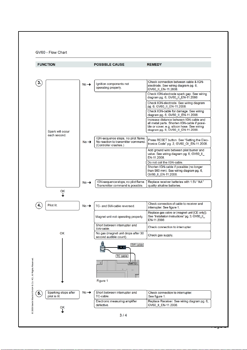
12. Appendix 1 – GV60 Installation Instruction

Page 37

Page 38
Page 39

Page 40

Page 41

Page 42

Page 43

0558
Manufactured By:
Multiglow Fires
Canterbury Road,
St. Nicholas-at-Wade,
Nr. Canterbury,
Kent CT7 0PQ
Telephone: 01843 847575
Fax: 01843 848300
Email: sales@multiglow.com
Web: www.multiglow.com
 Loading...