

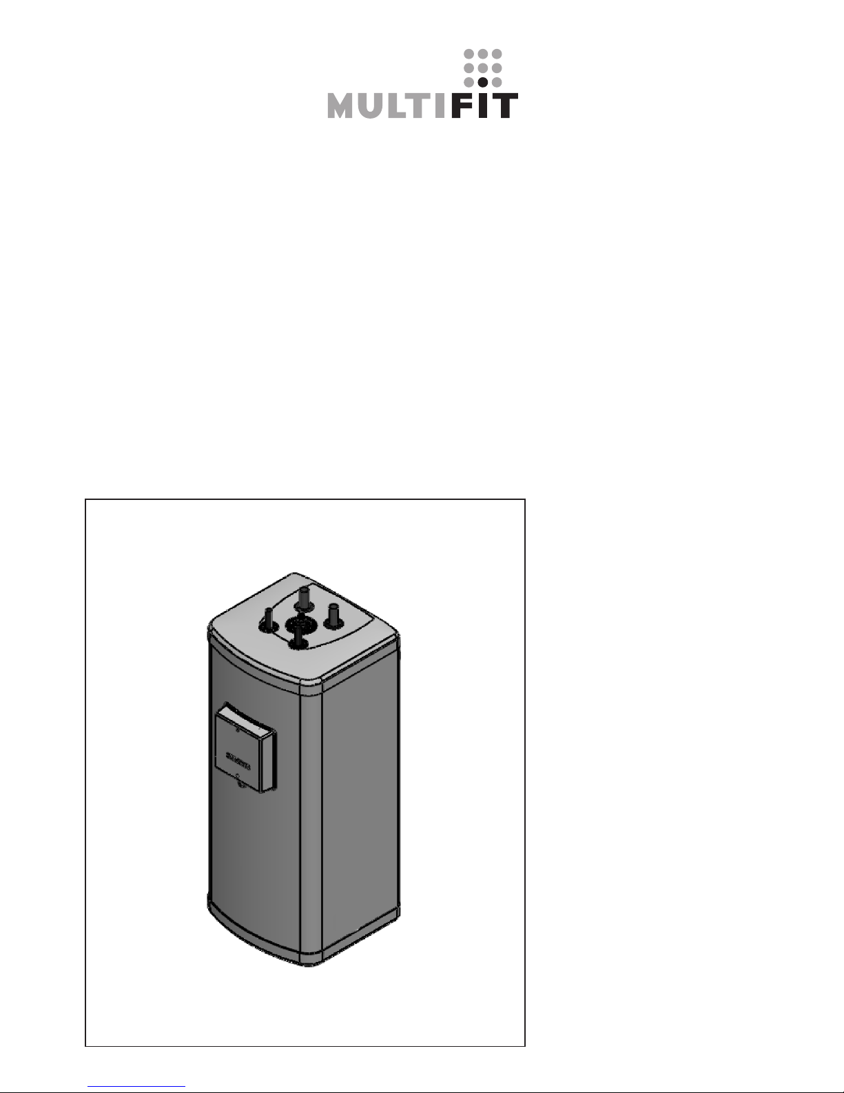
MULTIFIT Advance & HeatSaver Systems, Advance System, HeatSaver System, 720589801, 720721001 Installation Instructions Manual
Page 1
© Baxi Heating UK Ltd 2010
I N S TA L L AT I O N I N S T R U C T I O N S
Advance & HeatSaver Systems
Hot Water System incorporating:Passive Flue Gas Heat Recovery Device
50 Litre Temporal Store
Condensing Combination Boiler (Advance System only)
‘Low Profile’ Flue Elbow (Advance System only)
Part No. 720589801 - Advance System
Part No. 720721001 - HeatSaver System
Please leave these instructions with the
user for safe keeping, along with the boiler
Installation & Servicing Instructions.
Page 2

2
CONTENTS
1 Introduction ....................................... 2
2 Technical data ................................... 3
3 General information ........................... 6
4/5 Installation & Commissioning.............9
The MULTIFIT Advance & HeatSaver Systems are domestic hot water systems designed to provide a high level of
performance more efficiently.
The combination boiler will provide both central heating and domestic hot water at mains pressure.
The complete Advance package consists of a 40kW condensing combination boiler, GasSaver GS-1 22BV*,
Heatsaver Temporal Store Cylinder (50 litre), ‘Low Profile’ Flue Elbow, 8 litre expansion vessel and fittings kit. An 'S' plan
control system is also supplied. NOTE: No other control system should be used with the Advance or HeatSaver System.
When the 8 litre expansion vessel is fitted, total system volume can be up to 250 litres.
NOTE: The HeatSaver package DOES NOT include a condensing combination boiler or ‘Low Profile’ Flue Elbow. The boiler
and appropriate flue must be obtained separately.
*Design based on SuperFlow Technology by Zenex Technologies Ltd. and manufactured under licence. Zenex products
and technologies are protected under UK Patent Nos. 2420174 and 2451341 - Other patents pending.
The MULTIFIT Advance & HeatSaver Systems must be installed as detailed in these instructions. The boiler and GasSaver
must be
installed in accordance with the installation instructions supplied with them. Failure to do so will negate the warranty
supplied with the package.
The Advance & HeatSaver Systems have been approved to the relevant requirements of the Building Regulations for primary
hot water storage systems and to the UK Water Regulations.
It is the law that all gas appliances are installed by a competent person in accordance with the following recommendations:-
Current Gas Safety (Installation and Use) Regulations.
All current Building Regulations issued by the Department of Communities and Local Government (CLG) i.e. Approved
Document L1.
Building Standards (Scotland) (Consolidation) Regulations issued by the Scottish Government Built Environment
Directorate - Building Standards Division.
UK Water Regulations/Byelaws (Scotland)
Health & Safety Document No. 635 (The Electricity At Work Regulations 1989)
The installation should also be in accordance with the following British Standard Codes of Practice:-
BS 5440:1:2000 Flues
BS 5449:1990 Forced circulation hot water systems
BS 5546:2000 Installation of hot water supplies for domestic purposes
BS 6700:1997 Design, installation, testing and maintenance of services supplying water
BS 6798:2000 Installation of gas fired hot water boilers
BS 6891:1998 Gas installation
BS 7593:1992 Code of Practice for treatment of water in heating systems
BS 7671:2001 Requirements for electrical installations, IEE Wiring Regulations
Failure to install any part of the Advance or HeatSaver System correctly could lead to prosecution. It is in your own interest
and that of safety to ensure that the law is complied with.
Manufacturer's instructions must
NOT be taken in any way as over-riding statutory obligations.
It is essential that the primary system is thoroughly cleaned and flushed when fitting the Advance or HeatSaver System.
All cleaning agent must be removed and inhibitor added to the system - failure to do so will invalidate the warranty.
This appliance is not intended for use by persons (including children) with reduced physical, sensory or mental capabilities, or
lack of experience and knowledge, unless they have been given supervision or instruction concerning the use of the appliance
by a person responsible for their safety. Children should be supervised to ensure that they do not play with the appliance.
6 Short parts list ................................... 10
7 Routine inspection .............................. 10
8 Inspection history ............................... 11
1.0 Introduction
The MULTIFIT Advance & HeatSaver Systems have been designed to deliver domestic hot water at a high level of performance
more efficiently, for example the Advance System can provide18 l/min at temperatures of 50°C and above for long periods of
demand using less energy than a typical hot water storage system utilising a large cylinder.
The cold water supply first passes through the GasSaver where the reclaimed heat from the hot flue gasses is used to
pre-heat the cold water supply. This pre-heated water then passes through the coil in the 50 litre temporal store where it
is heated to a higher temperature. This hot water is then delivered to the blending valve where it is mixed with water direct from
the cold mains supply and enters the cold inlet of the combination boiler at a temperature of approximately 30°C. The boiler then
heats the water to the required temperature.
System Operation
TM
IMPORTANT
Page 3
3
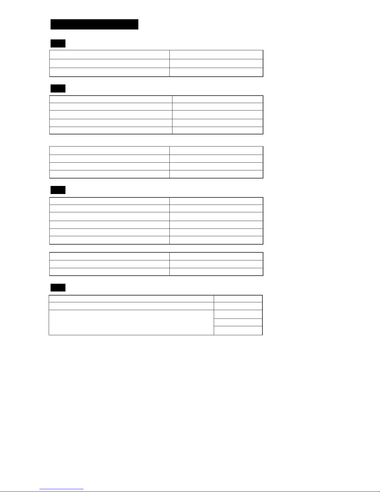
W = 366 D = 410 H = 910
Steel - White paint
PUR foam
Cylinder External Dimensions
Outer Case
Cylinder Insulation Material
500 kPa (5 bar)*
20 kPa (0.2 bar)
18 l/min
2.5 l/min
62°C
22mm
22mm
Copper
3.5 l
Maximum Inlet Water Pressure
Minimum Inlet Water Pressure
Maximum Water Flow Rate (Advance System only)
Minimum Water Flow rate
Outlet Water Temperature (approx. max.)
50 Litre Temporal Store
Mains Water Inlet Pipe Connection
Mains Water Outlet Pipe Connection
Coil Material
DHW Coil Water Capacity
* Note: If inlet water pressure
is above 500 KPa (5 bar)
a pressure reducing valve
must be fitted !
250 kPa (2.5 bar)
50 kPa (0.5 bar)
82°C
300 kPa (3 bar)
8 l at 80 kPa (0.8 bar)
100 kPa (1.0 bar)
15mm
Copper
50 l
Maximum Working Pressure
Minimum System Pressure
Maximum System Temperature (approx.)
Boiler Pressure relief Valve Setting
Boiler Exp. Vessel (pre-charge press.)
Recommended System Pressure (cold)
Flow and Return Connections
Cylinder Material
Nominal Cylinder Capacity
30°C
22 mm
8 l
1/2" BSP
Blending Valve Temperature Setting
Blending Valve Connections
Primary System Expansion Vessel Capacity
Connection
Pre-Charge Pressure
100 kPa (1 bar)
2.0 Technical Data
2.1 General
2.2 DHW System
2.3 Primary System
2.4 Components
50 Litre Temporal Store
Page 4
4
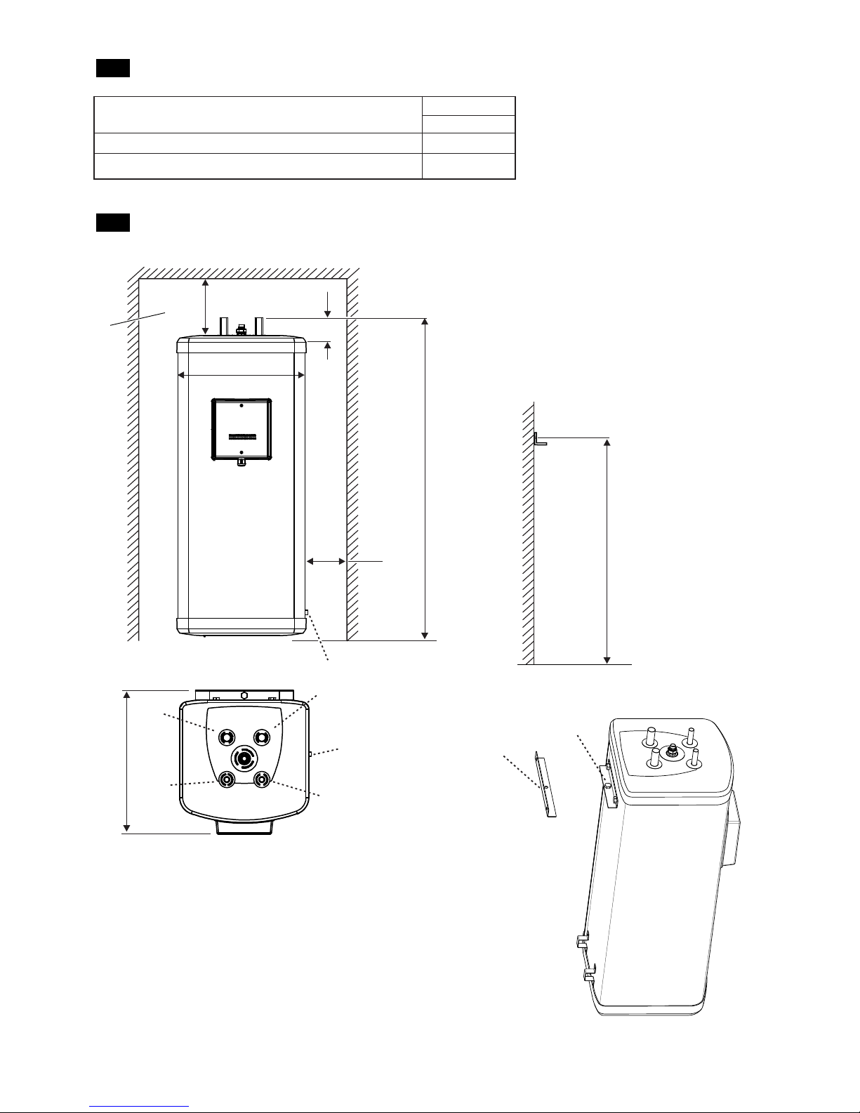
Minimum Clearances* for Servicing Top
)1 .giF ot refeR(
)ytpme( thgieW gnitfiL
Weight (full) including DHW and Primary Circuit
150 mm
100 mm
24 kg
74 kg
Fig. 1
Once the position of the store has been
determined the Wall Safety Bracket can
be fitted. Mark the wall 743mm from the
floor for the centreline of the bracket
securing holes. Mark through the holes
in the bracket, drill and plug the wall.
Secure the bracket.
Manouvre the store into position and
engage the locating bolt at the rear in
the wall bracket.
370 mm
150 mm
100 mm
Minimum
clearance
910 mm
D
E
C
B
A
snoitcennoC
A
B
C
D
E
- Mains Water Inlet 22mm (Blue collar)
- Hot Water Outlet 22mm (Red collar)
- Primary Return 15mm (Black collar)
- Primary Flow 15mm (Black collar)
- Drain Cock Tapping
*
50 mm
743 mm
436 mm
Clearances & Connections Wall Safety Bracket
Wall Safety
Bracket
Location
Bolt
2.5 Service Clearance & Weights
2.6 50 Litre Temporal Location
Drain Point (RH Side Only)
Minimum
clearance
*
E
Page 5
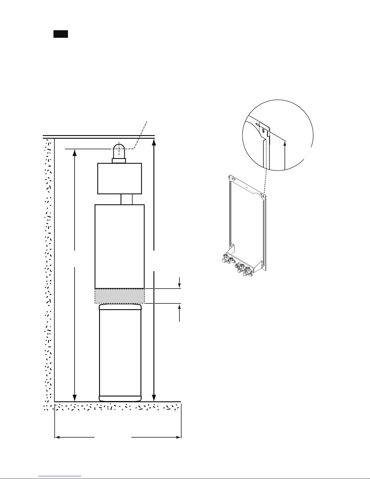
2243mm
to flue c/line
1780mm to horizontal
fixing slots
If it is desired to install the major components of the Advance System in stack format a MINIMUM floor-to-ceiling
height of 2320mm is required (Fig. 2).
The boiler template should be positioned that the centreline of the horizontal fixing slots in the wall mounting frame
is 1780mm from the floor (Fig. 3).
Also note the 800mm minimum width required if the 2 port valves and expansion vessel are to be installed in the
immediate vicinity of the store.
5
GasSaver GS-1
Combination
Boiler
Store
Fig. 2
Fig. 3
2.7 Stack Installation
Drill hole flue
116mm
MINIMUM
Height Required
2320mm
An area 150mm high
and the width of the boiler
must always be kept clear
MINIMUM
Width Required
800mm (if 2 port valves
& vessel are installed
adjacent)
Page 6
6
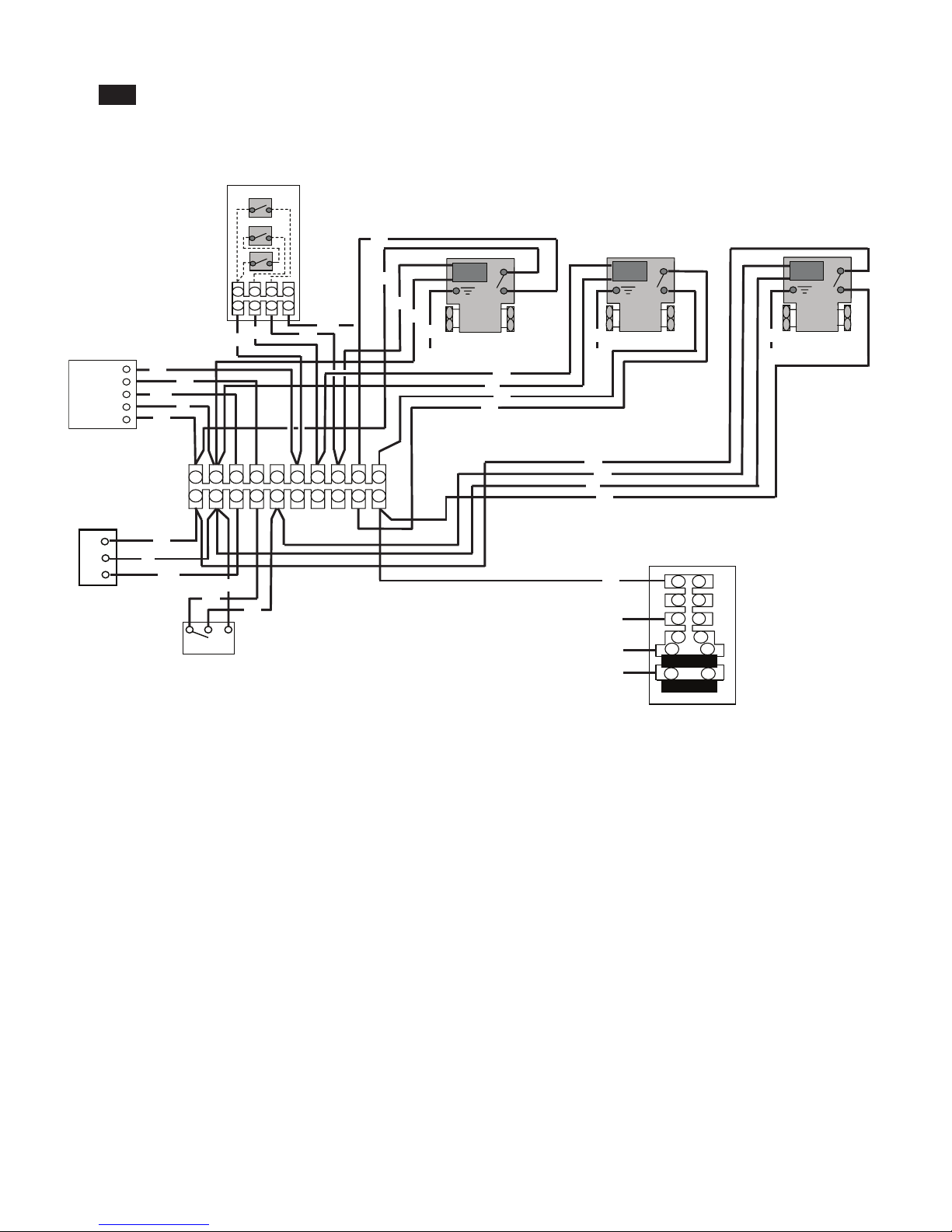
Fig. 4
Note: All earth connections must be linked back to the mains earth.
S Plan
Valve
Motor
S Plan
Valve
Motor
DHW On
HGT On
Earth
Neutral
Live
L
N
E
Room Stat
S Plan
Valve
Motor
Valve 1 (DHW safety)
Valve 3 (Heating)
Valve 2 (DHW)
Store Wiring
(internal wiring shown
as dotted lines)
gr
br
b
br
b
br
br
gr
gr
b
br
br
b
b
br
b
or
br
gr
or
1
2
or
or
or
br
gr
g/y
g/y
g/y
g/y
g/y g/y
g/y
b
br
Boiler Wiring
Programmer
Key
b - blue
br - brown
g/y - green/yellow
or - orange
gr - green
2.8 System Wiring
Page 7
7
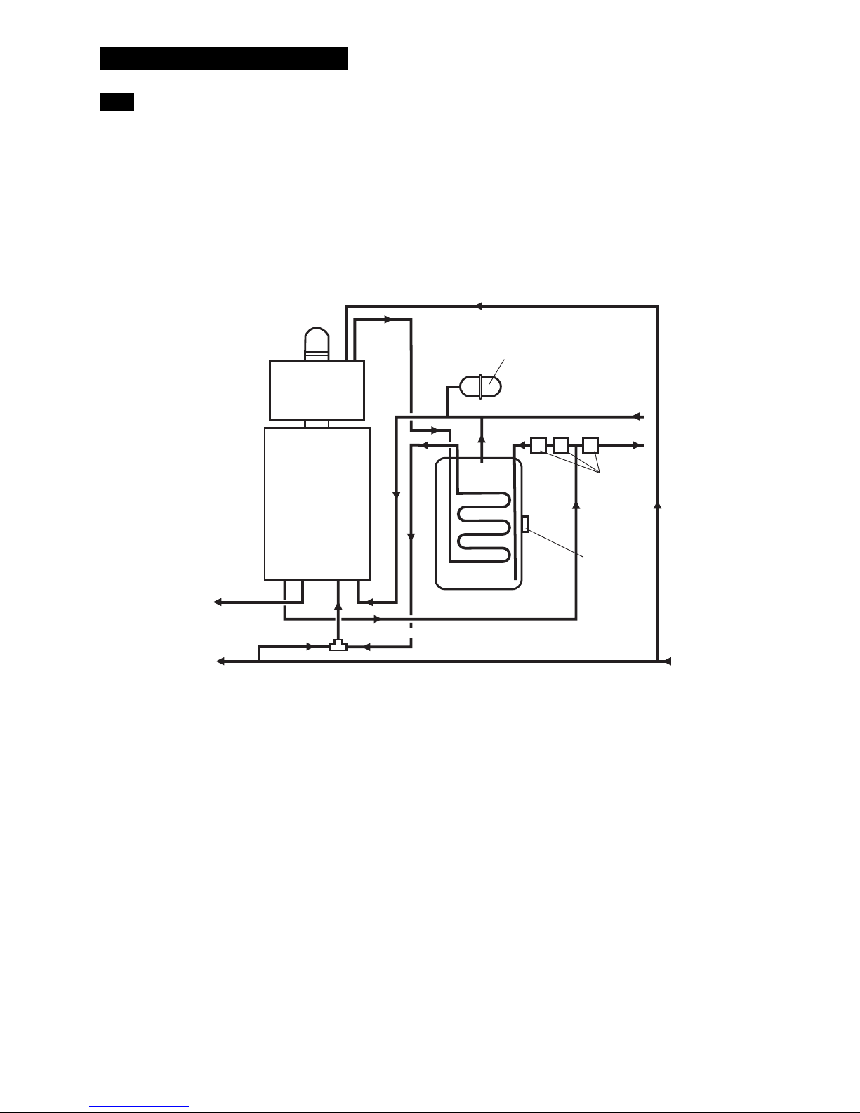
The Advance & HeatSaver Systems and pipework should be installed as shown in the schematic diagram below. It is important
that the three 2 port valves are installed so that they are fully accessible for any subsequent maintenance. Where the immersion
coil is fitted future access should also be taken into consideration.
The 50 litre temporal store should be positioned as close as possible to the boiler with the primary flow and return pipework to
the store no more than 1½ m in length. This pipework must be insulated.
All pipework carrying potable water (i.e. DHW) must be 22mm diameter to ensure 18l/min flow is achieved (Advance System only).
NOTE: This diagram is a SYMBOLIC REPRESENTATION to show the relative positions of the major components and
pipework, and illustrate the water flow. For example, the system can be as described in Section 2.7.
'S' plan control system
Fig. 5
Hot Water Outlet
To taps
Cold water Inlet
Primary Flow
Primary Return
Combination
Boiler
GasSaver
50 l Store
Cylinder
Thermostat
Blending/Check Valve
60°C and below
30°C
2 Port Zone
Valves
8 litre expansion vessel
75°C and below
2 31
3.0 General Information
3.1 System Pipework
Page 8

8
Note: Before installation, check that the incoming mains water supply is adequate to provide the required flow rates.
The minimum flow rate needed for the flow switch and burner to operate is 2.5 litres/min.
The incoming mains water pressure should be between 0.2 and 5 bar to ensure efficient operation. If the pressure is
above 5 bar a pressure reducing valve must be fitted.
To ensure economic use the pipe runs from the boiler should be in 15 mm copper pipe and be as short as possible.
Also where possible the pipework should be insulated to reduce heat loss.
All taps and mixing valves used with the hot water system must be suitable for operating at a mains pressure of up to 8 bar.
Showers - A shower may be used with the boiler if required.
If a loose or flexible head type shower is used it may require the fitting of a double check valve, to comply with Water Bye Law 17.
Bidets - No anti-syphonage arrangements are necessary, provided the outlets are shrouded and it is not possible to
attach a temporary hand held spray. A supply of direct mains fed hot and cold water is permitted provided the appliance
is of the over-rim flushing type.
Before the mains water supply pipe is connected to the boiler, it should be thoroughly flushed out to avoid the danger of
dirt or foreign matter entering the boiler.
It is essential that the primary system is thoroughly cleaned and flushed when fitting the Advance & HeatSaver Systems.
If a cleaning agent is used, it must be flushed out before inhibitor is added to the primary system. The cleaning agent and
inhibitor must be used in accordance with the manufacturers instructions. IMPORTANT: Only Fernox and Sentinel are
acceptable. Further information can be obtained from Fernox (Tel: 0870 870 0362) or Sentinel (Tel: 0800 389 4670).
All cleaning agents must be removed and inhibitor added to the system. Failure to do so will invalidate the warranty.
The system should be flushed in accordance with BS 7593 and BS 5449. The following procedures are recommended:
1. Installing onto a new system:a.Fill the system, vent at high points, at pump and radiators.
b.Check for leaks.
c. Rapidly drain the system.
d.If required, chemically clean the system as instructed by the recommended cleaner manufacturer.
Note: Ensure that the system is flushed to remove any remains of the cleaner.
e.If chemical cleaner is not used to clean the system:-
i) Refill the system.
ii) Switch on the boiler and allow the system to heat up to the normal operating temperature.
iii) Rapidly drain the system while the water is still hot.
iv) Refill the system.
f. As required, add the recommended inhibitor to the system as instructed by the inhibitor manufacturer.
g.Recheck for leaks.
2. When installing onto an existing system it must be thoroughly cleaned.
As required, add the recommended inhibitor to the system as instructed by the inhibitor manufacturer.
Check for leaks.
Refer to the instructions supplied with the boiler for full information. The Advance & HeatSaver Systems are supplied with
an 8 litre expansion vessel for fitting to the primary return pipework between the HeatSaver temporal store and the boiler
(See Fig. 5). This is to allow for the additional expansion required when fitting the 50 litre temporal store. The pre-charge
of the expansion vessel should be 1 bar.
The following P.V. Solar Panel kits are available for use in conjunction with the Advance & HeatSaver Systems:-
Product Part No. EAN Code
Multifit Solar PV 1st fix 1 panel roof kit (pan-tile) with D.C. element 720724201 5033313022853
Multifit Solar PV 1st fix 1 panel roof kit (slate-tile) with D.C. element 720724001 5033313022860
Multifit Solar PV 1st fix 1 panel roof kit (rosemary-tile) with D.C. element 720724101 5033313022877
Multifit Solar PV 1st fix 1 panel wall kit wall mountings kit with D.C. element 720575901 5033313022396
3.2 DHW System
3.3 Flushing the Heating System
3.4 Central Heating System
3.5 P.V. Solar Panel
Page 9
9
Note: When delivered on site do not unpack until ready for installation and store in a dry area.
Check all components are present (see Section 1.0 Introduction).
The boiler, flue and GasSaver must be fitted as described in the instructions supplied with the boiler and the GasSaver.
Advance System ONLY:-
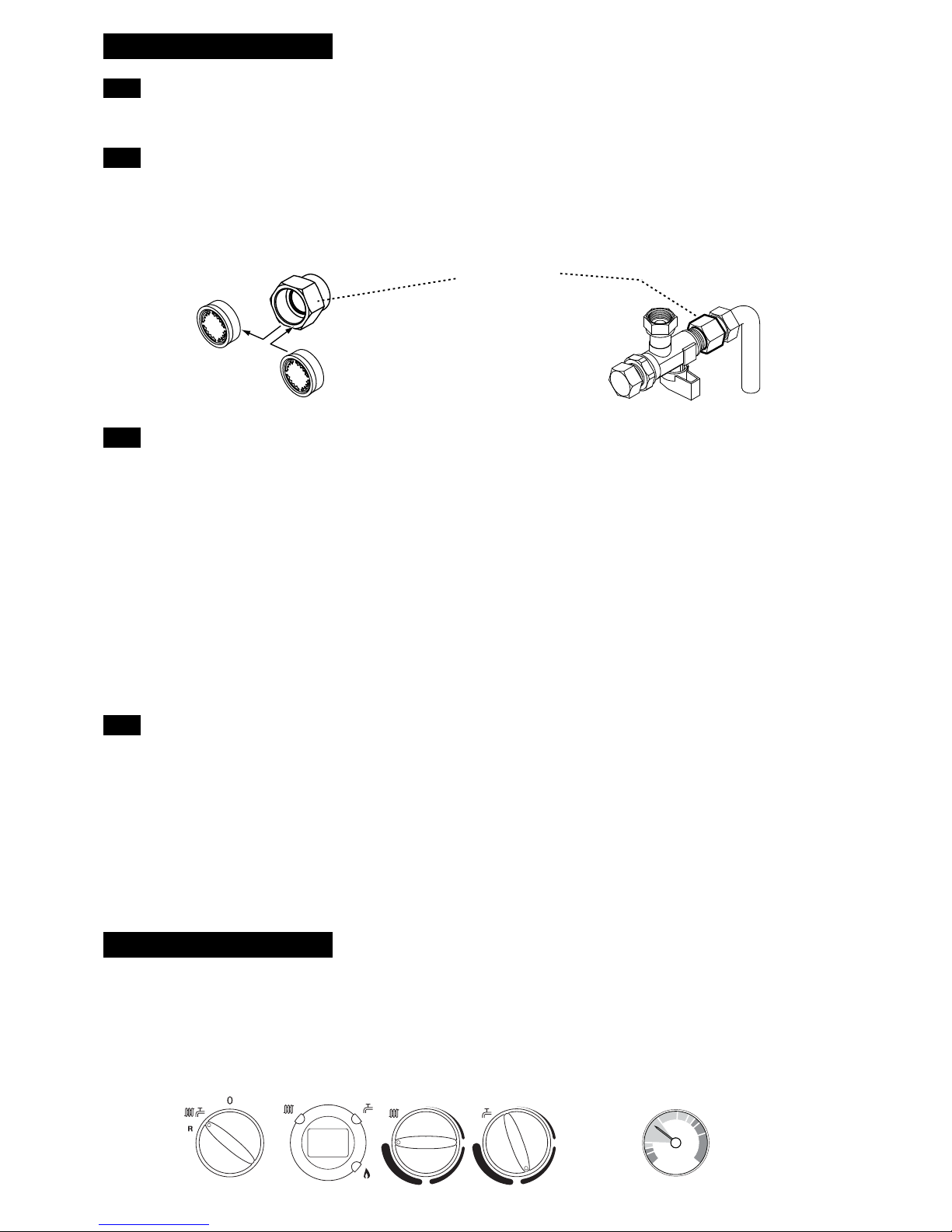
It is necessary to remove the blue/blue flow regulator from the cold water inlet connection on the boiler wall frame (Fig. 6).
Replace the regulator with the blue/grey one supplied.
1. Locate the primary store as close to the boiler as possible ensuring there are the minimum clearances available as given in
Section 2.5 and shown in Fig. 1. Section 2.7 shows the store, boiler & GasSaver in a stack installation.
Ensure the floor on which the store is mounted is capable of withstanding the weight of the store when full i.e. 74kg.
2. Connect the pipework - Refer to Figs. 1 and 5.
a. Fit the 3/4" BSP to 22 mm fittings and 3/4" BSP to 15 mm fittings supplied, to the primary store connections.
Fit the 3/4" BSP to 15 mm fittings to the primary flow and return connections (with the black collar) and the 3/4" BSP
to 15 mm fittings to the cold inlet (with the blue collar) and hot water outlet connections (with the red collar).
Connect the drain cock to the cylinder.
b. Thoroughly flush out all water pipework. Refer to Section 3.4.
c. Connect all primary system pipework referring to Fig. 5. Ensure that the following are connected:-
Connect the 'S' plan valves as shown in Fig. 5.
d. Connect all cold mains and hot water pipework as shown in Fig. 5. Ensure that the blending valve is connected to
the hot water outlet pipework from the store also shown in Fig. 5.
Note:
WARNING ! ISOLATE ELECTRICAL SUPPLY BEFORE REMOVING TERMINAL COVER
All electrical wiring must be carried out by a competent person to BS 7671 - Requirements for Electrical
Installations, IEE Wiring Regulations.
1. Connect the mains supply to the boiler terminal block as described in the instructions supplied with the boiler.
The electrical connections are shown in Fig. 4 of these instructions.
Note: An internal clock should not be fitted to the boiler when an Advance or HaatSaver System is connected.
An external 2-channel clock MUST be used instead.
2. Connect the 50 litre temporal store, 2-channel programmer, room thermostat and zone valves as described in the
instructions supplied with the 'S' plan control system kit.
Fig. 7
Domestic Hot WaterCentral Heating
Set to User Requirements
Set to Maximum
1. Fill all the systems, i.e. primary and secondary circuits and check for leaks. Refer to the boiler instructions.
2. Refer to Section 3.4 in these instructions and ensure the primary system has been flushed and cleaned and inhibitor
added to the primary system - failure to do so will invalidate the warranty !
3. Commission the boiler and GasSaver as described in the boiler and GasSaver installation instructions.
bar
0
1
2
3
4
Flow Regulator
Housing
Fig. 6
4.0 Installation
5.0 Commissioning
4.1 Unpacking
4.2 Fit the Boiler & GasSaver
4.3 Fit the 50 Litre Temporal Store Cylinder
4.4 Making Electrical Connections to the Controls
Blue Surround
& Blue Insert
Blue Surround
& Grey Insert
Typical Boiler
Control Panel
Page 10

10
Item Spare Part No.
8 litre expansion vessel
22mm Blending Valve 30°C
720576501
40615035
90003638
It is recommended that the 50 litre Temporal Store should be subject to a general condition inspection at each boiler
maintenance interval. Complete the Inspection Record on page 11.
If the system pressure exceeds 2.5 bar when operating at maximum temperature, the additional 8 litre expansion vessel
(refer to Fig. 5) as well as the boiler expansion vessel should be checked and re-pressurised, if necessary.
Notes: 1. Check the expansion vessel charge only when the system pressure is zero.
2. The expansion vessel pressure should be charged to 1 bar.
3. Function of the store should be checked: a) Ensure that when the store thermostat has operated valves 1 & 2 open
and the boiler calls for heat.
b) In the above condition valve 3 should be closed.
c) If, when the store is calling for heat, valves 1 & 2 are closed the thermostat
and safety cut-outs should be checked and reset if necessary.
2 Port Valve
6.0 Short Parts List
7.0 Routine Inspection
Page 11
11
It is recommended that the Advance or HeatSaver System is inspected regularly and that you complete the appropriate
Inspection Record below.
Service Provider: Before completing the appropriate Inspection Record below, please ensure you have carried out the
boiler service as described in the boiler instruction manual.
Date:
Engineer Name:
Company Name:
Telephone No.
Gas Safe Register No.
Comments:
Signature:
Date:
Engineer Name:
Company Name:
Telephone No.
Gas Safe Register No.
Comments:
Signature:
Date:
Engineer Name:
Company Name:
Telephone No.
Gas Safe Register No.
Comments:
Signature:
Date:
Engineer Name:
Company Name:
Telephone No.
Gas Safe Register No.
Comments:
Signature:
Date:
Engineer Name:
Company Name:
Telephone No.
Operative ID No.
Comments:
Signature:
Date:
Engineer Name:
Company Name:
Telephone No.
Gas Safe Register No.
Comments:
Signature:
Date:
Engineer Name:
Company Name:
Telephone No.
Gas Safe Register No.
Comments:
Signature:
Inspection 2
Inspection 3
Inspection 4
Inspection 5
Inspection 6
Inspection 7
Inspection 8
Date:
Engineer Name:
Company Name:
Telephone No.
Gas Safe Register No.
Comments:
Signature:
Inspection 1
8.0 Inspection Report
Page 12

© Baxi Heating UK Ltd 2010
7206638-01 (11/10)
All descriptions and illustrations provided in this leaflet have been
carefully prepared but we reserve the right to make changes and
improvements in our products which may affect the accuracy of the
information contained in this leaflet. All goods are sold subject to our
standard Conditions of Sale which are available on request.
MUL TI FIT
A Registered Trade ma rk o f Ba xi Heating UK Ltd (3879156)
Brooks House, Coventry Road, Warwick. CV34 4LL
Technical Enquiries 0844 871 1555
Websites:- www.baxiheating.co.uk
e&oe
 Loading...