

Page 1

MFT 102/103hsm Labeler
Operator Manual
Document No. 3906330
Document Revision 0D
Multifeeder Technology
4821 White Bear Parkway
St. Paul, MN 55110
651-407-3100 ww w.multifeeder.com
Page 2

This page is intentionally blank.
Page 3

This page is intentionally blank.
Page 4

Table of Contents
Introduction 6
Icon Definitions 6
Viewing Electronic Manual 8
Viewing Printed Manual 9
Safety 10
Personal Safety Warnings 10
Machine Precautions 11
Hazard Warnings 12
Hazard Warnings - Cutout 13
Terminology 14
Main Body and Power Unwind 14
Rewind Assembly Options 16
Vacuum Take Up Rewind 16
Power Take Up Rewind 16
Vacuum Take Up Rewind Configuration 17
Power Take Up Rewind Configuration 17
Peel Plate Assembly 18
Typical Media 18
Labeler Control Box - Exterior 20
Labeler Control Box - Interior 22
Keypad Detailed 24
Setup 26
Sequence of Operation 26
Labeler Control Box Power Up 28
Labeler Thread Pattern 30
General Labeler Thread Pattern 30
Power Unwind Media Sensor Box 32
With Power Unwind and Vacuum Take Up 34
With Power Unwind and Power Take Up 36
Standard Product Sensor Setup 38
Standard Product Sensor Setup - Continued 40
Standard Product Sensor Setup - Continued 42
Label Stop Position 44
Label Stop Position - Continued 46
Labeler Speed Adjustment 48
Page 5

Labeler Basic Menu - Settings Menu 50
Labeler Basic Menu - Settings Menu (continued) 52
Non-Standard Product Sensor Setup 54
Non-Standard Product Sensor Setup - Continued 56
Non-Standard Product Sensor Setup - Continued 58
Label Product Sensor Advanced Calibration 60
Label Product Sensor Advanced Calibration - Continued 62
Label Product Sensor Advanced Calibration - Continued 64
Label Product Sensor Advanced Calibration - Continued 66
Ready-to-Run Checklist 70
Notes 71
Maintenance 72
Preventative Maintenance 72
Daily 72
Weekly 72
Semi-Annually 72
Annually 72
Maintenance Log 73
Control Box External Connections 74
Control Box Intercommunication Wiring 75
Product Dimensions 76
MFT 102hsm 76
MFT 103hsm 76
Spare Parts 77
Terms and Conditions 78
Page 6

TerminologySafetyIntroduction
Maintenance
Terms/ConditionsSetup
Introduction
Below is a description of the sections contained in the manual. You may also navigate to a specic
section in the electronic version of this manual by clicking on one of the section tabs above.
Safety - The Safety section outlines the general safety precautions you should use when operating
your MFT equipment.
Terminology - The Terminology section describes the main components of your MFT equipment and
introduces you to terminology used later in the manual.
Setup - The Setup section provides instructions for basis setup the MFT equipment.
Maintenance - The Maintenance section describes the basic maintenance necessary to ensure
optimal performance of your MFT equipment.
Terms and Conditions - Multifeeder Standard Terms and Conditions.
Icon Definitions
Caution - This icon is used to alert you to very important safety instructions.
Tip - This icon is used to alert you to helpful information or operational tips.
Important - This icon is used to alert you to important information.
[ 6 ]
Page 7

TerminologySafetyIntroduction
Maintenance
Terms/ConditionsSetup
Congratulations on the purchase of your new equipment from Multifeeder Technology, Inc. This
document is designed to provide you with the information about the basic set operation of the MFT
equipment.
This manual may not illustrate optional equipment purchased with your unit or units. Multifeeder
Technology (MFT) designed this equipment to be used by operators with basic knowledge of machine
functions. In order for your MFT equipment to operate as intended, the equipment must be properly
installed and basic maintenance must be performed at regular intervals. Compromised performance
and unsafe operation may result from unauthorized modication. Unauthorized modications of any
kind will void the product warranty and are strongly discouraged. This equipment requires operation by
properly trained personnel in accordance with all the applicable, operation and maintenance manuals
using approved product and procedures.
Technical phone support is available by calling (651) 407-3100 Monday - Friday, 8 am to 5 PM (CST).
Please have direct access to your MFT system when you call.
[ 7 ]
Page 8

Viewing Electronic Manual
TerminologySafetyIntroduction
Maintenance
Terms/ConditionsSetup
As viewed on a typical monitor.
When viewing this manual electronically. It is best viewed with Adobe Reader® version 9.0 or later.
Adobe Reader® version 9.0 version allows the for full display and inter activity features of this manual.
Furthermore, set the display settings to view to “Two-Up” and “Show Cover Page During Two-Up”.
That ensure the manual will be displayed as intended.
[ 8 ]
Page 9

11
1 Base Feeder
2 Base Feeder Pressure Roller
3 Tipping Feeder
4 Tipping Feeder Pressure Roller
5 Shingling Conveyor
6 Height Adjustable Stand
7 Glue System Tank
8
9
10 Glue System Control Box
11
12 Shingling Conveyor Control Box
Terms/ConditionsSetup
Maintenance
SafetyIntroduction Terminology
Viewing Printed Manual
TerminologySafetyIntroduction
Maintenance
Terms/ConditionsSetup
Terminology
System Overview
6 7
SafetyIntroduction Terminology
2 31 4 5
119 10 12
8
10
Maintenance
Terms/ConditionsSetup
When printing this manual, print in color and two sided. This allows the printed pages to be placed into
a three ring binder as illustrated above with the graphics on the left and the denitions on the right.
Illustration Page Denition Page
[ 9 ]
Page 10

TerminologyIntroduction Safety
Maintenance
Terms/ConditionsSetup
Safety
Personal Safety Warnings
All equipment from Multifeeder Technology is designed with safety in mind. However, in
order to ensure your safety and the safety of others around you, common sense must
always be used when using this machine. Please read the all of the manuals provided
carefully before operating any of your MFT equipment.
• Do not install or use your MFT equipment without rst reading each of the individual
component manuals completely prior to operation.
• Use proper lifting techniques when removing MFT equipment and associated components
from the shipping box.
• Always power down equipment before making any adjustment or clearing jams.
• Never use a knife or sharp instrument to make an adjustment to the MFT equipment, or to
clean or clear jams on the MFT equipment.
• The MFT equipment may be unplugged in an emergency.
• Be aware that air cylinder (if equipped) may actuate during power up and power down
sequences.
• Be aware the MFT could cycle unexpectedly if the MFT equipment is not placed into a safe
mode.
• Make sure loose jewelry, clothing, long hair, neckties, etc., are properly secured before you
operate the MFT equipment.
• Always power down the MFT equipment and disconnect the power cord before working with
any of the MFT equipment’s electrical components or when performing maintenance tasks.
• This machine operates on mains voltage. Contact with this voltage may lead to serious injury,
or death.
• Do not use the MFT equipment, make mechanical adjustments, or perform maintenance
tasks while under the inuence of drugs or alcohol.
[
10
]
Page 11

Terms/ConditionsSetup
Machine Precautions
All equipment from Multifeeder Technology is designed with safety in mind. However, in
order to ensure your safety and the safety of others around you, common sense must
always be used when using this machine. Please read this section of the manual carefully
before operating your MFT equipment.
TerminologyIntroduction Safety
Maintenance
• Do not install or use your MFT equipment without rst reading each of the individual
component manuals completely prior to operation.
• Always power down the MFT equipment and disconnect the power cord before working with
any of the MFT equipment’s electrical components or when performing maintenance tasks.
• Use proper lifting techniques when removing MFT equipment and related components from
the shipping box.
• Make sure the MFT equipment is securely mounted before enabling the motor. The machine
may also be unplugged in an emergency.
• Use only fuses of the correct type, voltage, and current ratings. (5 x 20mm, 10A, 250V).
• Do not stack items on the machine even when it is not in use.
• Always power down equipment before making any adjustment or clearing jams.
• Perform regular maintenance on your MFT equipment. Failure to do so may result in
damage to the machine or machine operators.
• Maintenance tasks should be performed according to the methods described in this manual
by properly trained personnel.
• This system is intended to operate within the following environmental range: Temperature
10-35˚C (50-95˚F), the recommended relative humidity range of 30% to 60% with 80%
maximum, non-condensing.
• This machine should be operated in a well lit area.
• This machine should not be operated around loose cords.
• This machine should not be operated around loose tools or objects such as screw drivers,
pliers, paper clips, or anything that may accidentally interfere with normal operation.
[
11
]
Page 12

Hazard Warnings
TerminologyIntroduction Safety
Maintenance
Terms/ConditionsSetup
Read and understand the entire manual
before operating the equipment.
Use common sense when operating the
equipment.
Do not operate the equipment while
distracted.
This equipment is intended to be
operated by trained and qualified
personnel.
Make sure loose jewelry, clothing, long
hair, neckties, etc., are properly secured
before you operate the MFT equipment.
This machine operates on mains
voltage. Contact with this voltage may
lead to serious injury, or death.
[
]
12
Page 13

TerminologyIntroduction Safety
Maintenance
Terms/ConditionsSetup
Hazard Warnings - Cutout
Print this page separately to cutout the hazard warning illustrations and afx it to the equipment as required.
[
13
]
Page 14
SafetyIntroduction Terminology
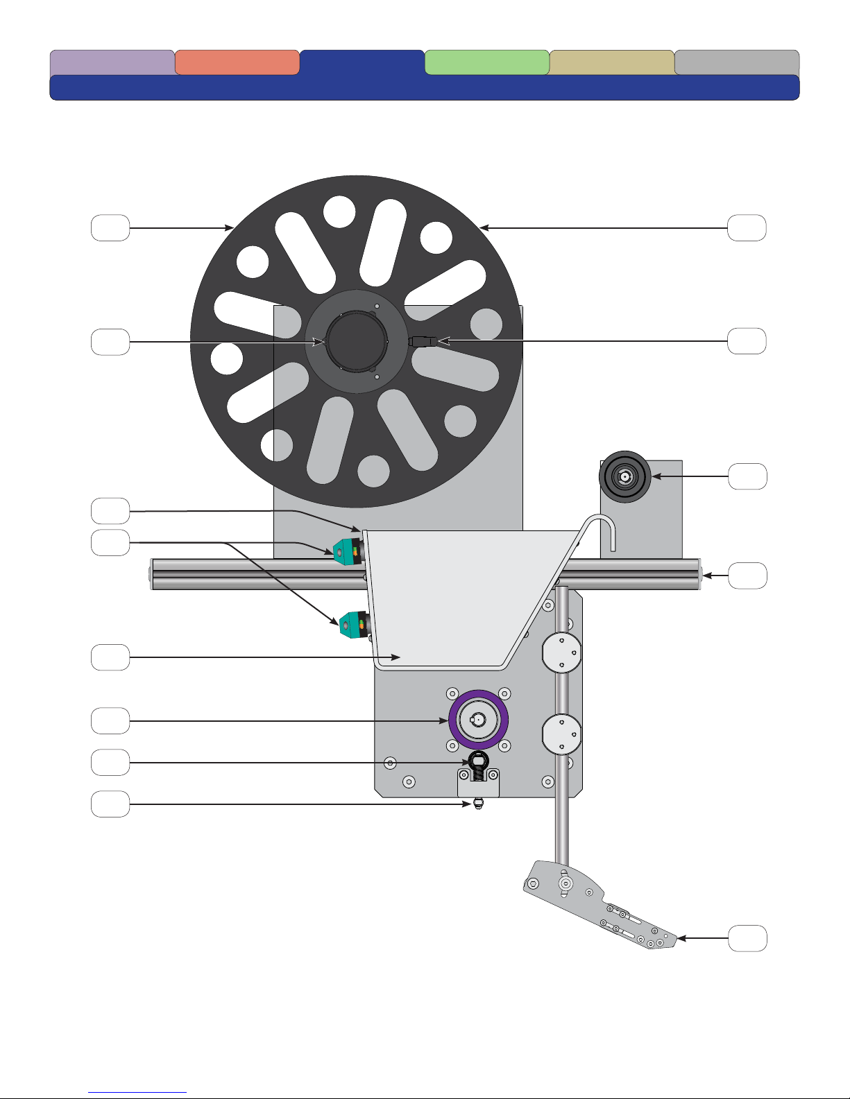
Terminology
Main Body and Power Unwind
1 9
Maintenance
Terms/ConditionsSetup
2
3
4
5
6
10
11
12
7
8
[
14
13
]
Page 15

SafetyIntroduction Terminology
Maintenance
1 Power Unwind Media Back Plate
2 Power Unwind Hub
3 Power Unwind Media Sensor Box
4 Power Unwind Media Sensor
5 Power Unwind Media Sensor Box Label Width Adjustment Plate
6 Main Drive Roller
7 Main Drive Pinch Roller
8 Main Drive Pinch Roller Pull Down Bar
Terms/ConditionsSetup
9 Power Unwind Media Front Plate
10 Power Unwind Media Front Plate Locking Lever
11 Media Guide Roller
12 Main Mounting Bar
13 Peel Plate Assembly
[
15
]
Page 16

SafetyIntroduction Terminology
Rewind Assembly Options
Vacuum Take Up Rewind
1
Maintenance
Terms/ConditionsSetup
2
3
Power Take Up Rewind
1
4
5
6
4
7
2
3
[
16
5
8
6
]
Page 17

SafetyIntroduction Terminology
Maintenance
Terms/ConditionsSetup
Vacuum Take Up Rewind Power Take Up Rewind
1 Vacuum Take Up Mount 1 Power Take Up Rewind Hub Back Plate
2 Vacuum Take Up Device 2 Power Take Up Rewind Hub
3 Vacuum Take Up Device Pipe 3 Power Take Up Rewind Dancer Arm
4 Vacuum Take Up Device Mounting Bracket 4 Power Take Up Rewind Main Housing
5 Vacuum Take Up Device Entry Cap 5 Power Take Up Rewind Upper Idler Roller
6 Vacuum Take Up Device Entrance 6 Power Take Up Rewind Lower Idler Roller
7 Upper Rewind Dancer Arm Sensor
(Shown behind dancer arm cutaway)
8 Lower Rewind Dancer Arm Sensor
Vacuum Take Up Rewind Configuration Power Take Up Rewind Configuration
[
17
]
Page 18

Peel Plate Assembly
1
2
SafetyIntroduction Terminology
Maintenance
Terms/ConditionsSetup
3
4
5
6
Typical Media
7
8
1
2 3 4
[
18
]
Page 19

SafetyIntroduction Terminology
Peel Plate Assembly
1 Peel Plate Mounting Rods
2 Peel Plate Media Guide Roller with Adjustable Guide Rings
3 Product (Label) Sensor Pair Mounting Rod
4 Upper Product (Label) Sensor
5 Lower Product (Label) Sensor
6 Product (Label) Sensor Pair Mounting Rod Adjustment Slot
7 Peel Plate
Maintenance
Terms/ConditionsSetup
8 Peel Edge
Typical Media
1 Media
2 Liner
3 Label
4 Gap
[
19
]
Page 20

SafetyIntroduction Terminology
Labeler Control Box - Exterior
2
1
Maintenance
RESET
Terms/ConditionsSetup
3
4
2
[
20
5
]
Page 21

SafetyIntroduction Terminology
Maintenance
Terms/ConditionsSetup
1 Mounting Tabs - Used to mount the Control Box to the production line.
2 Motor Connection - Connects the Control Box to the labeler motors.
3 Primary Keypad - Allows operator to access and adjust labeler settings.
4 System Reset Button - Allows the operator to reset the labelers interlock system.
5 Cover Cam Latch - Used to latch the cover closed.
[
21
]
Page 22

SafetyIntroduction Terminology
Labeler Control Box - Interior
1
Maintenance
RESET
Terms/ConditionsSetup
2
3
[
22
]
Page 23

SafetyIntroduction Terminology
Maintenance
Terms/ConditionsSetup
The interior of the control box houses all of the electronics required to operate the labeler.
Labeling systems with a vacuum take-away will contain 2 servo-drive controllers while a system
with a powered rewind will contain 3 servo-drive controllers. See page 15 for conguration examples.
1 Primary Keypad - Allows operator to access and adjust the labeler’s main drive settings.
2 Powered Unwind Keypad - Allows operator to access and adjust the labeler’s powered unwind
settings.
3 Powered Rewind Keypad - Allows operator to access and adjust the labeler’s powered rewind
settings.
[
23
]
Page 24

Keypad Detailed
SafetyIntroduction Terminology
14
Maintenance
Terms/ConditionsSetup
1
2
4 1186 7
3 105 12
9
13
[
24
]
Page 25

SafetyIntroduction Terminology
Maintenance
Terms/ConditionsSetup
1 On/Off Key - Used before/after turning on the Main On/Off Switch.
2 Auto On/Off Key - Used to enable or disable the automatic application cycle startup.
3 Menu Key - Used to enter and navigate the menu system.
4 Numeric Keys - Used to enter values in various menu settings.
5 Enter Key - Used to enter value changes in various menu settings.
6 Clear/Cancel Key - Used to clear or cancel values entered in various menu settings and stop
certain function of the feeder.
7 Stop Motor Key - Used to stop or de-energies the drive motor.
8 Change Speed Key - Used to change the dispense speed.
9 Set Product Thickness- Used during media setup.
10 Cycle Start Key - Used to start the application cycle.
11 Jog To Clear Key - Used to feed the label to the end of the peel plate.
12 Jog Key - Used to jog or feed the media or label . The drive continuously feed while this key is
pressed.
13 Display - Used to display functions and menu setting.
14 Function Keys - Used to display certain functions and menu settings.
[
25
]
Page 26

SafetyIntroduction Terminology Setup
Setup
Sequence of Operation
Maintenance
Terms/Conditions
4
3
2
1
[
26
]
Page 27

SafetyIntroduction Terminology Setup
Maintenance
Terms/Conditions
1 The Labeler receives a signal to begin the application cycle.
2 The Main Drive Roller engages and moves the label until the Product (Label) Sensor is triggered
by the gap.
3 The Power Unwind Media Sensor is triggered as the media is used up and triggers the Power
Unwind to supply additional media into the Power Unwind Media Box.
4 The Rewind Dancer Arm Sensor on the Power Rewind is triggered and takes up the slack in the
liner as it develops during the application.
[
27
]
Page 28

J3-Low Product
J4-RS 232
Remote Keypad
SafetyIntroduction Terminology Setup
Labeler Control Box Power Up
Action Displayed
Maintenance
Terms/Conditions
1
2
=
=
STATUS: OFF
PRESS ON TO ENABLE EQUIPMENT
MODE: XXXXXXXXX MODE
F1 - TECHNICIAN F2 - FACTORY
MODE: ADVANCED TIPPING MODE AUTO OFF
STATUS: READY PRODUCT COUNT 1
PROGRAM NUMBER 1
[
28
]
Page 29

SafetyIntroduction Terminology Setup
Maintenance
Terms/Conditions
Be curtain that you have read and understand ALL of the Safety Section before powering
up or setting up any Multifeeder Equipment.
1 Turn on the main Power Switch and wait until you see illustrated screen is displayed.
2 Press the On Key to complete the Power On Sequence.
[
29
]
Page 30

SafetyIntroduction Terminology Setup
Labeler Thread Pattern
General Labeler Thread Pattern
Maintenance
Terms/Conditions
1
3
6
2
4
5
[
30
]
Page 31

SafetyIntroduction Terminology Setup
Maintenance
Terms/Conditions
1 Place the roll of labels onto the Power Unwind Hub such that the label exits the top of the roll in
the direction of the Peel Plate.
2 Form a loop within the Power Unwind Media Sensor Box.
3 Thread the media around the Media Guide Roller.
4 Thread the media around the Peel Plate Media Guide Roller and between the Upper and Lower
Product (Label) Sensor Pair.
5 Thread the media over the Peel Plate and around the Peel Edge removing any labels from the
liner after the Peel Edge as illustrated by the dashed line.
6 Thread the liner under the Main Drive Pinch Roller and then between the Main Drive Pinch Roller
and the Main Drive Roller Using the Main Drive Pinch Roller Pull Down Bar. Continue threading
the liner around the Main Drive Roller and to the rewind device. Note: Alternative thread pattern is
available if required.
Common Thread Pattern Alternative Thread Pattern
[
31
]
Page 32

SafetyIntroduction Terminology Setup
Power Unwind Media Sensor Box
1
Maintenance
Terms/Conditions
2
[
32
]
Page 33

SafetyIntroduction Terminology Setup
Maintenance
Terms/Conditions
1 Verify the Power Unwind Media Sensor is properly positioned to trigger with the media being
applied.
2 Use the 4 screws to adjust the Power Unwind Media Sensor Box Label Width Adjustment Plate to
control the side-to-side movement of the media.
[
33
]
Page 34

SafetyIntroduction Terminology Setup
With Power Unwind and Vacuum Take Up
Maintenance
1
Terms/Conditions
7
3
2
6
[
34
4
5
]
Page 35

SafetyIntroduction Terminology Setup
Maintenance
Terms/Conditions
1 Place the roll of labels onto the Power Unwind Hub such that the label exits the top of the roll in
the direction of the Peel Plate.
2 Form a loop within the Power Unwind Media Sensor Box.
3 Thread the media around the Media Guide Roller.
4 Thread the media around the Peel Plate Media Guide Roller and between the Upper Product
(Label) Sensor Pair.
5 Thread the media over the Peel Plate and around the Peel Edge removing any labels from the
liner after the Peel Edge as illustrated by the dashed line.
6 Thread the liner under the Main Drive Pinch Roller and then between the Main Drive Pinch Roller
and the Main Drive Roller Using the Main Drive Pinch Roller Pull Down Bar. Continue threading
the liner around the Main Drive Roller and to the rewind device.
7 Place a length of liner material into the Vacuum Take Up Device Entrance. The length will vary
depending on the characteristics of the Liner.
Common Thread Pattern Alternative Thread Pattern
[
35
]
Page 36

SafetyIntroduction Terminology Setup
With Power Unwind and Power Take Up
Maintenance
1
Terms/Conditions
10
3
2
9
6
8
7
[
36
4
5
]
Page 37

SafetyIntroduction Terminology Setup
Maintenance
Terms/Conditions
1 Place the roll of labels onto the Power Unwind Hub such that the label exits the top of the roll in
the direction of the Peel Plate.
2 Form a loop within the Power Unwind Media Sensor Box.
3 Thread the media around the Media Guide Roller.
4 Thread the media around the Peel Plate Media Guide Roller and between the Upper Product
(Label) Sensor Pair.
5 Thread the media over the Peel Plate and around the Peel Edge removing any labels from the
liner after the Peel Edge as illustrated by the dashed line.
6 Thread the liner under the Main Drive Pinch Roller and then between the Main Drive Pinch Roller
and the Main Drive Roller Using the Main Drive Pinch Roller Pull Down Bar. Continue threading
the liner around the Main Drive Roller and to the rewind device.
7 Thread the liner underneath the Power Take Up Rewind Lower Idler Roller.
8 Thread the label around the Power Take Up Rewind Dancer Arm.
9 Thread the label around the Power Take Up Rewind Upper Idler Roller.
10 Wrap the liner several times around Power Take Up Rewind Hub.
Common Thread Pattern Alternative Thread Pattern
[
37
]
Page 38

SafetyIntroduction Terminology Setup
Standard Product Sensor Setup
1
Maintenance
Terms/Conditions
2
Sensor Safe Area
[
38
]
Page 39

.
SafetyIntroduction Terminology Setup
Maintenance
Terms/Conditions
In normal operation, the label product sensor can be setup by positioning the last 5 mm of the trailing
SET PROD
edge of the label below the product sensor and then pressing the
key. If however, the labeler
THICKNESS
product sensor has been moved and becomes seriously out of adjustment, the following setup
instructions will restore the labeler product sensor to normal operation:
1 When required use an 1.5mm allen wrench to align the emitter and receiver as illustrated.
2 Position the labeler product sensor within the safe sensor area that is 5mm from any edge of the
label.
Continue on the next page.
[
39
]
Page 40

SafetyIntroduction Terminology Setup
Standard Product Sensor Setup - Continued
Action Displayed
Maintenance
Terms/Conditions
2
3
=
=
MAIN 1/2 : MENU KEY FOR NEXT
1. SETTINGS 4. REPORTS
2. PROGRAMS 5. IDENTIFICATION
3. SETUP 6. DIAGNOSTICS
SYSTEM DIAGNOSTICS 1/4 : MENU FOR NEXT
1.STACK LIGHT 4.PSTART/LOW-P INPUT
2.PRODUCT SENSOR 5.LOW PRODUCT OUTPUT
3.LINE SPEED ENC 6.AUTO ON OUTPUT
[
40
]
Page 41

MENU
6
SafetyIntroduction Terminology Setup
Continue from previous page.
3
From the READY screen on the controller, press the
4
Press the
key to select DIAGNOSTICS.
Continue on the next page.
key.
Maintenance
Terms/Conditions
[
41
]
Page 42

SafetyIntroduction Terminology Setup
Standard Product Sensor Setup - Continued
Action Displayed
Maintenance
Terms/Conditions
4
6
=
SYSTEM DIAGNOSTICS ITEM 2 OF 24
PRODUCT SENSOR
1-4 SELECTED(0):1=XXX,2=XXX,3=XXX,4=XXX
5
7
=
8
MODE: ADVANCED TIPPING LABELER
STATUS : READY PRODUCT COUNT 1
PROGRAM NUMBER
=
CHECKING PRODUCT THICKNESS
PLEASE WAIT...
[
]
42
Page 43

2
.
SafetyIntroduction Terminology Setup
Maintenance
Terms/Conditions
Continued from previous page.
4
Press the
key to select PRODUCT SENSOR.
5 Sensor drive #3 should ideally be between 90-110.
6 If the labeler has not been feeding correctly and sensor drive #3 is not between these values you
should loosen the top half of the product sensor and move it until the values fall between 90-110.
When the numbers are in range tighten the top half of the sensor drive to lock it in place.
CLEAR
7
Press the
CANCEL
key until you return to the READY screen.
8
Press the
your settings.
SET PROD
key. The labeler product sensor is now ready. It is recommended that you save
THICKNESS
Note - For alternate or non-standard sensor setup go to page 50.
[
43
]
Page 44

Label Stop Position
1
SafetyIntroduction Terminology Setup
Maintenance
Terms/Conditions
2
3
Label Stop Position
Action Displayed
MAIN 1/2 : MENU KEY FOR NEXT
1. SETTINGS 4. REPORTS
=
=
2. PROGRAMS 5. IDENTIFICATION
3. SETUP 6. DIAGNOSTICS
PRODUCT LENGTH (M-F3), DEFAULT: 210
RANGE: 5-1500 mm
CURRENT: 150 NEW: 150
[
44
]
Page 45

SafetyIntroduction Terminology Setup
Maintenance
Terms/Conditions
The Label Stop Position is where the label stops with respect to the Peel Edge after an application
cycle. However certain applications may require adjusting the Label Stop Position. Follow the
instructions below to adjust the Label Stop Position as required.
1 The Stop Position is the where the label stops after the completion of an application cycle.
2
From the READY screen on the controller, press the
3
Press the key to select SETTINGS.
Continue on the next page.
Note - Follow the rules below to ensure proper label feeding when adjusting the Label Stop
Position.
MENU
key.
• Never use a minimum product length longer than the length of the label.
• Never use a minimum product length that makes the label stop past the sensor. If this happens,
then instead move the sensor down-stream so the product stops under the sensor.
• This distance and location are dependent on:
• Length of label
• Speed of labeler
• Deceleration value for motor
• Desired stop position of the label on peel plate
[
45
]
Page 46

SafetyIntroduction Terminology Setup
Label Stop Position - Continued
Action Displayed
Maintenance
Terms/Conditions
4
10X
5
6
=
=
MIN PRODUCT LENGTH (M-F3), DEFAULT: 0
RANGE: 0-1000 mm
CURRENT: 0 NEW: 0
MODE: ADVANCED TIPPING LABELER
STATUS : READY PRODUCT COUNT 1
PROGRAM NUMBER
[
46
]
Page 47

MENU
SafetyIntroduction Terminology Setup
Maintenance
Terms/Conditions
Continued from previous page.
4
Press the
key 10 times to navigate to the Minimum Product Length screen and enter the new
value.
CLEAR
5
Press the
CANCEL
key until you return to the READY screen.
6 Some applications may require the repositioning of the Product (Label) Sensors. Do this by
loosening the bolts on the Product (Label) Sensor Pair Mounting Rod and repositioning as
required.
[
47
]
Page 48

SafetyIntroduction Terminology Setup
Labeler Speed Adjustment
Action Displayed
Maintenance
Terms/Conditions
1
2
3
4
=
=
MACHINE SPEED (M-F30, DEFAULT: 50
RANGE: 1-140 MPM
CURRENT: 50 NEW: 50
+
NEW VALUE OF 92
SUCCESSFULLY STORED
MODE: ADVANCED TIPPING LABELER
STATUS : READY PRODUCT COUNT 1
=
PROGRAM NUMBER
[
48
]
Page 49

SafetyIntroduction Terminology Setup
Maintenance
1 Press the Change Speed Key.
2 Enter the desired Machine Speed value by using the Number Keys.
3 Press the Enter Key. The screen will briey display:
Terms/Conditions
NEW VALUE OF
[
the entered value
]
SUCCESSFULLY STORED
After three (3) seconds the screen will return to the Machine Speed setting screen.
CLEAR
4
Press the
CANCEL
key until you return to the READY screen.
If you keyed an incorrect value, press the Clear Cancel Key to re-enter the value.
[
49
]
Page 50

SafetyIntroduction Terminology Setup
=
Labeler Basic Menu - Settings Menu
Action Displayed
Maintenance
Terms/Conditions
1
2
3
=
=
=
MAIN 1/2 : MENU KEY FOR NEXT
1. SETTINGS 4. REPORTS
2. PROGRAMS 5. IDENTIFICATION
3. SETUP 6. DIAGNOSTICS
PRODUCT LENGTH (M-F3), DEFAULT: 210
RANGE: 5-1500 mm
CURRENT: 210 NEW: 210
MAX JOG SPEED (S), DEFAULT: 20
RANGE: 1-100
CURRENT: 20 NEW: 20
4
=
5
SIGNAL DELAY (M-F3), DEFAULT: 0
RANGE: 0-30000
CURRENT: 0 NEW: 0
SIGNAL PERIOD (M-F3), DEFAULT: 0
RANGE: 0-10000
CURRENT: 0 NEW: 0
[
50
]
Page 51

SafetyIntroduction Terminology Setup
Maintenance
Terms/Conditions
Basic menu setting allow the operator control over common adjustments required for basic setup.
More advanced menu settings are available through the password protected Technicians Menu. Press
the key from the ready screen to access the operator available settings illustrated on the previous
page.
1
Press the key from the ready screen to access the sub-menu.
2
Press the key from the sub-menu to access the settings screen and the Product Length
setting. This setting allows the operator to adjust the Product (Label) Length the labeler looks for
when feeding a label.
3
Press the from the previous screen to enter the Max Jog Speed setting. This setting
allows the operator to adjust the speed the labeler jogs a label when the key or the is
pressed.
4
Press the from the previous screen to enter the Signal Delay setting. This setting allows the
operator to adjust when the labeler begins applying the label. In effect the position of the label on
the product it is applied to.
5
Press the from the previous screen to enter the Signal Period setting. This setting allows
the operator to adjust how many start signal are ignored before triggering an application cycle.
For example, with the value set to 0, no start signals are ignored and every start signal triggers
an application cycle by the labeler. With a value of 21, 21 start signals are require to trigger an
application cycle.
Continue on the next page.
[
51
]
Page 52

SafetyIntroduction Terminology Setup
Labeler Basic Menu - Settings Menu (continued)
Action Displayed
Maintenance
Terms/Conditions
6
7
=
=
NO PRODUCT LIMIT (M-F3), DEFAULT: 240
RANGE: 15-255
CURRENT: 240 NEW: 240
PRODUCT SEPARATION(0.1 mm units) (M-F3)
RANGE: 1-1000, DEFAULT: 5
CURRENT: 5 NEW: 5
[
52
]
Page 53

SafetyIntroduction Terminology Setup
Maintenance
Terms/Conditions
Continued from previous page.
6
Press the from the previous screen to enter the No Product Limit setting. This setting allows
the operator to adjust the value the Product (Label) Sensor uses to determine when a label gap is
detected. See page 58.
7
Press the from the previous screen to enter the Product Separation setting. This setting
allows the operator to adjust the Label Gap settings for non-standard labels.
Continue on the next page.
[
53
]
Page 54

SafetyIntroduction Terminology Setup
Non-Standard Product Sensor Setup
1
Maintenance
Terms/Conditions
2
3
J3
Action Displayed
MAIN 1/2 : MENU KEY FOR NEXT
1. SETTINGS 4. REPORTS
=
=
2. PROGRAMS 5. IDENTIFICATION
3. SETUP 6. DIAGNOSTICS
MAIN 2/2 : MENU KEY FOR NEXT
1. DEMO MODE 4. LANGUAGE
2. TECHNICIAN
3. FACTORY
[
54
]
Page 55

MENU
SafetyIntroduction Terminology Setup
Maintenance
Terms/Conditions
The Multifeeder Technology high speed labeling system allows the use of non standard product or
label sensors to meet specic application requirements. Follow the instructions below to connect
and enable the non standard product or label sensor. Follow the instructions specic to the sensor to
ensure the sensor function properly in your application.
1 Connect the non Standard Sensor to J3.
2 Navigate to the Advanced Sensor settings. From the READY screen on the controller, press the
key.
3
Press the to navigate to the Main 2/2 screen.
Continue on the next page.
[
55
]
Page 56

SafetyIntroduction Terminology Setup
Non-Standard Product Sensor Setup - Continued
Action Displayed
4
ENTERING TECHNICIAN SETTINGS MENU
Maintenance
Terms/Conditions
5
Enter
[ ]
Password
6
7
=
=
=
TYPE PASSWORD TO CONTINUE [ ]
TECHNICIAN 1/4 : MENU KEY FOR NEXT
1. MOTOR 4. ADVANCED SETTINGS
2. FEEDING 5. DIGITAL I/O
3. DEBOUNCE 6. WIZARDS
DIGITAL I/O 1/4 : MENU KEY FOR NEXT
1. STANDARD I/O SIGNALS
2. DUPLICATE SIGNALS
3. PRODUCT SENSOR
NO PRODUCT LIMIT (M-F3), DEFAULT: 240
RANGE: 15-255
=
8
=
CURRENT: 240 NEW: 240
ADVANCED PRODUCT SENSOR (S), DEFAULT: 0
RANGE: 0=OFF, 1-9=PORT
CURRENT: 0 NEW: 0
3X
[
56
]
Page 57

SafetyIntroduction Terminology Setup
Maintenance
Continued from previous page.
4 Enter the Technician Level password. (See Note)
5 Entering the Technician Level password displays the Technician 1/4 screen.
6
Press the key to navigate to the Digital I/O screen.
7
Press the key to enter the Product Sensor menu options.
Terms/Conditions
8
Press the
MENU
key 3 times to navigate to the Advanced Product Sensor setting.
Note - The password is disclosed during the install and training or available by contacting the
Multifeeder Technology service department at (651) 407-3100 during normal business hours in
the central time zone.
[
57
]
Page 58

SafetyIntroduction Terminology Setup
Non-Standard Product Sensor Setup - Continued
Action Displayed
Maintenance
Terms/Conditions
9
10
=
=
ADVANCED PRODUCT SENSOR (S), DEFAULT: 0
RANGE: 0=OFF, 1-9=PORT
CURRENT: 9 NEW: 9
MODE: ADVANCED TIPPING LABELER
STATUS : READY PRODUCT COUNT 1
PROGRAM NUMBER
[
58
]
Page 59

SafetyIntroduction Terminology Setup
Maintenance
Continued from previous page.
9
Press the key to set J3 as the input port for the non standard product sensor.
CLEAR
10
Press the
CANCEL
key until you return to the READY screen.
Terms/Conditions
[
59
]
Page 60

SafetyIntroduction Terminology Setup
Label Product Sensor Advanced Calibration
Maintenance
Terms/Conditions
1
2
Labels and Sensor
Side View
Sensor Prole
1
3
4
2
6
255
7
5
[
60
0
]
Page 61

SafetyIntroduction Terminology Setup
Maintenance
Terms/Conditions
The label or product sensor is calibrated at the factory and will function without adjustment for the
majority of applications. However certain applications may require adjusting sensor parameters to
achieve maximum performance. Follow the instructions below to calibrate the sensor as required.
1 This illustration shows the sensor, label and liner relationship as viewed from the side. The sensor
components consist of an upper emitter 1 and a lower receiver 2. The sensor is calibrated to
detect the gap or space 3 between labels on the liner 4.
2 This illustration shows the sensor prole. The sensor prole is a graphic representation of what
the sensor “sees” as the media passes through it. The wavy line 5 is the sensor value when
the sensor is seeing the label and liner and the spike 6 is the sensor value when the label sees
the label gap or liner only. The graph 7 represents numerical values of what the sensor might
see. The values range from 0 to 255. Where 0 is a completely opaque material and 255 is a
completely transparent material.
A software algorithm is used to determine the actual value required to indicate wether the sensor is
seeing a label or gap. In some applications this value may need to be adjusted manually. Follow the
instructions on the following pages to determine and set the Sensor No Product Value.
Continue on the next page.
[
61
]
Page 62

SafetyIntroduction Terminology Setup
Label Product Sensor Advanced Calibration - Continued
3
Maintenance
Terms/Conditions
Action Displayed
4
=
5
=
MAIN 1/2 : MENU KEY FOR NEXT
1. SETTINGS 4. REPORTS
2. PROGRAMS 5. IDENTIFICATION
3. SETUP 6. DIAGNOSTICS
SYSTEM DIAGNOSTICS 1/4 : MENU FOR NEXT
1.STACK LIGHT 4.PSTART/LOW-P INPUT
2.PRODUCT SENSOR 5.LOW PRODUCT OUTPUT
3.LINE SPEED ENC 6.AUTO ON OUTPUT
[
62
]
Page 63

6
SafetyIntroduction Terminology Setup
Continued from previous page.
3 Remove any labels from the liner as illustrated.
Maintenance
Terms/Conditions
4
From the READY screen on the controller, press the
5
Press the
key to select DIAGNOSTICS.
Continue on the next page.
MENU
key.
[
63
]
Page 64

SafetyIntroduction Terminology Setup
Label Product Sensor Advanced Calibration - Continued
Action Displayed
Maintenance
Terms/Conditions
6
=
Value=(255–(Drive 3 Value))x(.25)+(Drive 3 Value)
8
SYSTEM DIAGNOSTICS ITEM 2 OF 24
PRODUCT SENSOR
1-4 SELECTED(0):1=255,2=255,3=102,4=36
7
Example:
9
=
MODE: ADVANCED TIPPING LABELER
STATUS : READY PRODUCT COUNT 1
PROGRAM NUMBER
[
64
]
Page 65

2
SafetyIntroduction Terminology Setup
Maintenance
Continued from previous page.
6
Press the
key to select PRODUCT SENSOR.
7 Note the value of #3, referred to as “Drive 3”. In this example a value of 102.
8 Enter the value into the No Product Sensor Value formula as illustrated.
CLEAR
9
Press the
CANCEL
key until you return to the READY screen.
Continue on the next page.
Terms/Conditions
[
65
]
Page 66

SafetyIntroduction Terminology Setup
Label Product Sensor Advanced Calibration - Continued
Action Displayed
Maintenance
Terms/Conditions
10
11
12
=
=
=
MAIN 1/2 : MENU KEY FOR NEXT
1. SETTINGS 4. REPORTS
2. PROGRAMS 5. IDENTIFICATION
3. SETUP 6. DIAGNOSTICS
MAIN 2/2 : MENU KEY FOR NEXT
1. DEMO MODE 4. LANGUAGE
2. TECHNICIAN
3. FACTORY
ENTERING TECHNICIAN SETTINGS MENU
TYPE PASSWORD TO CONTINUE [ ]
13
Enter
[ ]
Password
14
=
=
TECHNICIAN 1/4 : MENU KEY FOR NEXT
1. MOTOR 4. ADVANCED SETTINGS
2. FEEDING 5. DIGITAL I/O
3. DEBOUNCE 6. WIZARDS
DIGITAL I/O 1/4 : MENU KEY FOR NEXT
1. STANDARD I/O SIGNALS
2. DUPLICATE SIGNALS
3. PRODUCT SENSOR
[
66
]
Page 67

MENU
SafetyIntroduction Terminology Setup
Maintenance
Terms/Conditions
Continued from previous page.
The following instructions guide you through navigating and entering the No Product Sensor
Value determined from the previous page.
10
From the READY screen on the controller, press the
11
Press the key to navigate to the Main 2/2 screen.
12
Enter the Technician Level password. (See Note) Press the key.
key.
13 Entering the Technician Level password displays the Technician 1/4 screen.
14
Press the key to navigate to the Digital I/O screen.
Continue on the next page.
Note - The password is disclosed during the install and training or available by contacting the
Multifeeder Technology service department at (651) 407-3100 during normal business hours in
the central time zone.
[
67
]
Page 68

SafetyIntroduction Terminology Setup
Action Displayed
Maintenance
Terms/Conditions
15
16
=
=
NO PRODUCT LIMIT (M-F3), DEFAULT: 240
RANGE: 15-255
CURRENT: 240 NEW: 140
MODE: ADVANCED TIPPING LABELER
STATUS : READY PRODUCT COUNT 1
PROGRAM NUMBER
[
68
]
Page 69

SafetyIntroduction Terminology Setup
15 Use the keypad to enter the value calculated from page 60.
CLEAR
16
Press the
CANCEL
key until you return to the READY screen.
Maintenance
Terms/Conditions
[
69
]
Page 70

SafetyIntroduction Terminology Setup
Ready-to-Run Checklist
□ Verify the media is loaded and labels are removed
from the liner after the Peel Plate.
□ Verify the media is properly triggering the Power
Unwind Media Sensor and the Power Unwind Media
Sensor Box Label Width Adjustment Plate is position
properly.
Maintenance
Terms/Conditions
□ Verify the Product (Label) Sensor is properly adjusted
by pressing the several times verifying the label
stops consistently along the Peel Edge.
□ Verify the operation of the rewind. Turn on
the pneumatics for the Vacuum Take Up Rewind
conguration (if required) or set the Control Box to Auto
On for the Powered Take Up conguration.
□ Set the control box to Auto On and press Cycle Start
to activated for the Labeler.
Sensor Safe Area
RESET
[
70
]
Page 71

Notes
SafetyIntroduction Terminology Setup
Maintenance
Terms/Conditions
[
71
]
Page 72

Maintenance
Terms/ConditionsTerminologySafetyIntroduction Setup
Maintenance
Preventative Maintenance
Proper operation of your Multifeeder equipment is dependent on a regularly
preventative maintenance scheduled and inspection program. The generic
scheduled outlined in this section may need to be adjusted to your specific
application and environmental conditions.
Warnings
• Before any maintenance tasks are performed, the power must be disconnected from the Feeder.
• Use only a 50% isopropyl alcohol and water solution unless otherwise noted. Other cleaning
agents may damage the material.
• Isopropyl alcohol is very ammable! Use only in an open area away from any source of ignition,
including open ame or sparks.
• Be certain that the belts are completely dry before operating equipment. Damp belts may slip or
track incorrectly causing injury or damage to the equipment.
• ONLY USE CLEAN DRY AIR IF PNEUMATIC AIR IS REQUIRED FOR YOUR APPLICATION.
Daily
• Clean any debris from the equipment with a clean cloth dampened with the alcohol/water
solution.
• Visually inspect the rollers and guides for damage or unusual wear.
• Visually inspect the machine for loose screws, bolts, and adjustment knobs.
Weekly
• Inspect the photo optic sensors with clean lint free cloth dampened with the alcohol/water
solution if necessary.
• Inspect any belt pulleys for looseness and tighten if necessary. With the power cable
disconnected the pulleys may be rotated manually.
• Remove any adhesive buildup.
Semi-Annually
• Open the side covers and remove any accumulated debris if necessary.
Annually
• Inspect all belts, bearings and timing belts for wear and replace if necessary.
[
72
]
Page 73

Maintenance
Terms/ConditionsTerminologySafetyIntroduction Setup
Maintenance Log
Date Type Comments Initials
10-10-05 Weekly Cleaned glue built up on peel plate idler roller. DM
[
73
]
Page 74

J4 - RS232/Remote Keypad
Control Box External Connections
Maintenance
Terms/ConditionsTerminologySafetyIntroduction Setup
J24 - Motion Stop J22 - Signal Light
J10 - RS485
J7 - Descrete I/O
Lower Unwind Sensor
J24 J22
J23
J10
J7
J6
J25
J6 - Product Sensor
J25 - RS232
Lower Rewind Sensor
Vacuum Rewind
Upper Unwind Sensor
J1 - Start Sensor
Main
Encoder
Main
Motor
Unwind
Encoder
Unwind
Motor
J1 J2
Rewind
Encoder
Rewind
Motor
Upper Rewind Sensor
J2 - APL Interface
J3 - Low Product
Module
[
74
J4
J3
Power Entry
]
Page 75

Control Box Intercommunication Wiring
Upper Sensor Rewind
Lower Sensor Rewind
Maintenance
Upper Sensor Unwind
Lower Sensor Unwind
Terms/ConditionsTerminologySafetyIntroduction Setup
J6
1 2 3
Optional/Non-Standard
4
J3
Label Sensor
1
2
3
4
Standard Label Sensor
Labeler Drive Labeler Unwind
Labeler Rewind
[
75
]
Page 76

Product Dimensions
MFT 102hsm
Maintenance
Terms/ConditionsTerminologySafetyIntroduction Setup
MFT 103hsm
[
76
]
Page 77

Spare Parts
Part # Part Description
4598108 HSL Drive Roller Assembly
7105301 Motor 800W 950 With Plugs
1002600 Bearing 174012
1710109 R-W EKL020B 19x16 Mod
1528200 Sleeve Bearing 081210
4503600 Drive Roller Idler Block
1395301 HSL Drive Traction idler
Maintenance
Terms/ConditionsTerminologySafetyIntroduction Setup
1522400 Roller Sleeve 7/8 16Id
1155900 Timing Belt 15X59
1055600 Timing Pulley 051534 16 Keyed
1055700 Timing Pulley 051534 16 Mod.
1554200 Thrust Washer GTM 1630-015
3003000 5/8 Needle Roller Bearing
1002600 Ball Bearing 174012
For Use with Power Rewind Only
3091801 Compression Spring Lc042G 085
1712100 Spring Retaining
To order spare parts:
Send fax to 651-407-3199 with part numbers and pricing on company P.O, or Call 651-407-3100.
We do require a faxed company P.O. before shipment. Please indicate on P.O. the date you need the
parts delivered. We ship all orders UPS Ground unless specied on your purchase order.
[
77
]
Page 78

TerminologySafetyIntroduction Terms/Conditions
Setup
Maintenance
Terms and Conditions
MULTIFEEDER TECHNOLOGY, INC. (MFT) TERMS AND CONDITIONS
ALL SALES ARE SUBJECT TO THE FOLLOWING TERMS AND CONDITIONS.
1. Definitions.
1.1 “Accessory Products” mean spare parts purchased, at Buyer’s option, to enhance the System or replace components within the
System.
1.2 “Agreement” means this Sale Agreement.
1.3 “Buyer” means the person or entity that enters into this Agreement for the design and for manufacture of the System, subsystem accessory
products, or related services and/or Buyer’s assigns, successor’s agents and transferees.
1.4 “Default Specifications” means the MFT Default Specifications set forth in Exhibit A, attached hereto, which set forth the default functional
and technical performance criteria for the System.
1.5 “Final Product Throughput” means the end-product as fully processed by the MFT System.
1.6 “MFT” means Multifeeder Technology, Inc.
1.7 The “Operation and Maintenance Manual” means the operative and instruction guide supplied by Seller to Buyer, which addresses one or
several of the devices, components or Subsystems within the System.
1.8 “Order” means Buyer’s order in the form of Seller’s Proposal, signed by Buyer and delivered to Seller.
1.9 “Order Acknowledgement Form” means the written form Seller sends to Buyer indicating that Seller is in receipt of Buyer’s
Or der.
1.10 “Parties” means the Buyer and Multifeeder Technology, Inc.
1.11 “Product Samples” mean Buyer-supplied components and/or material to be fed through and/or processed by the System to create a Final
Product Throughput.
1.12 “Product Schedule” means the actions undertaken by MFT to design and build the System over a period of time.
1.13 “Production Schedule Date” means the date upon which production is scheduled for completion.
1.14 “Proposal” means Seller’s written description of the System and/or Accessory Products
1.15 “Quote” means the price quote for the System and/or Accessory Products.
1.16 “Seller” means Multifeeder Technology Inc.
1.17 “Shipment Date” means the estimated date upon which MFT anticipates shipment of the System from the MFT facility.
1.18 “Specifications” means the functional and technical per formance criteria for the System, as agreed-to by the Parties.
1.19 “Subsystem” means any smaller MFT-designed system that constitutes a component of the overall System.
1.20 “System” means the custom-designed product manufactured by Seller according to the Specifications, which may or may not include various
other Subsystems.
[
78
]
Page 79

TerminologySafetyIntroduction Terms/Conditions
1.21 “System Manual” means the operative and instruction guide supplied to Buyer by Seller with the shipment of the System, which addresses the
overall System, and may or may not address each separate device, component or Subsystem within the System
2. The System.
2.1 Purchase and Supply. Seller will sell the System and/or Accessory Products to Buyer under the terms and conditions set forth in this
Agreement.
2.2 Spec ifications . The System will be manu factured by Seller ac cording to the Spe cificatio ns. The Proposal wil l include a Quote for ea ch component
of the System. If the Buyer does not provide specif ications prior to the Quotation process, the Default Specifications will apply. All specif ications
supplied by Buyer are subject to (a) MFT’s written approval and (b) signature by a MFT-authorized representative.
2.3 Pa cking. Unless o therwise s pecified i n this Agreement or B uyer’s Order, the System and /or all Access ory Produc ts are to be packed and i dentified
in accordance with customary industry practice. Seller shall mark each container with necessary lifting, loading and shipping information,
including the applicable purchase order number, date of shipment, and the name and address of Seller and Buyer.
3. Assent to Terms and Conditions of Agreement. Unless otherwise indicated, Seller’s Proposal will expire thirty (30) days following the date the
Proposal is transmitted to Buyer. Seller’s Proposal is not binding upon Seller until Buyer’s Order is accepted in writing by Seller on an Order
Acknowledgement Form. Buyer’s Order must be submitted within the time frames provided herein.
Setup
Maintenance
4. Price, Price Adjustment & Additional Charges.
4.1 Price. The purchase price for the System will be set forth in the Quote. The pricing of Accessory Products is subject to change from time to
time.
4.2 Price Adjustment. The purchase price in the Quote may be increased to reflect increases in the cost of materials or labor, if:
4.2.1 Shipment of the System is scheduled for a date that is more than three (3) months after the date of Buyer’s Order;
4.2.2 Shipment of the System is delayed by Buyer to a date that is more than three (3) months after the date of Buyer’s Order; or
4.2.3 Shipment of the System is accelerated due to an accelerated Production Schedule Date.
4.3 Delivery, Risk of Loss and Title. The System will be delivered f.o.b. Seller’s Minnesota facility. Buyer will pay all packaging, handling and
freight to Buyer’s destination. Risk of loss or damage to the System passes to Buyer at the time of delivery to the carrier. Seller will purchase
shipping insurance at Buyer’s request and at Buyer’s expense. Transfer of title is not deemed to occur until payment in full has been
received by Seller. Shipment dates are Seller’s best estimate of when product(s) will be shipped or delivered, but the Shipment Date is not
guaranteed.
4.4 Ta xes. Buyer will pay all duties and taxes including sales, use, property, excise, value added and gross receipts taxes levied on the System
or Accessory Products. Seller will not collect an otherwise applicable tax if Buyer’s purchase is exempt from Seller’s collection of such tax
and a valid tax exemption certificate is furnished by Buyer to Seller.
4.5 Cancellation of Orders. Following Seller’s acceptance of Buyer’s Order, the Order can be cancelled only with Seller’s written consent. A
minimum cancellation charge of 35% of the purchase price of the System or Accessory Products will be assessed and will var y according to
the date on which the cancellation occurs in the Production Schedule, the quantity of work and materials that are salvageable, the degree to
which the System is custom-designed, and other factors in MFT’s sole discretion.
4.6 Additional Charges. Additional work completed or time consumed by reason of Buyer’s alterations or delays caused by Buyer, will be charged
to Buyer at Seller’s current price for work or material at the time of such alterations, changes, or delays.
[
79
]
Page 80

TerminologySafetyIntroduction Terms/Conditions
5. Payment.
5.1 Payment of Purchase Price. If Seller approves Buyer for credit, the payment schedule is (a) 55% of the purchase price in certified or other
currently available funds within five (5) days following acceptance of Buyer’s Order; (b) no later than ten (10) days before Buyer’s requested
shipment date (i) 35% of the purchase price in certified funds; and (ii) the remaining balance by Buyer’s delivery of an irrevocable letter of
credit or some other MFT-approved payment alternative, drawn on a U.S. bank in an amount equal to the remaining balance due for the benefit
of Seller or Seller’s agent. The letter of credit and/or its equivalent must be drawn on a financial institution and in form reasonably acceptable
to Seller, must be in U.S. dollars, and will expire no earlier than 60 days after the requested shipment date. Under no circumstances will
Seller be liable to Buyer for delays in shipment caused by Buyer’s delay in payment. If Seller does not approve Buyer for credit, payment will
be disbursed to Seller within five (5) days following acceptance of Buyer’s Order by certified or other currently available funds or by Buyer’s
delivery of an irrevocable letter of credit or some other MFT-approved payment alternative, drawn on a U.S. bank in an amount equal to the
full amount of the purchase price. The letter of credit and/or its equivalent shall provide for interim draws in accordance with the schedule
referenced in the preceding paragraph, be drawn on a financial institution and in form reasonably acceptable to Seller, in U.S. dollars, and will
expire no earlier than 60 days after the requested shipment date. Buyer authorizes Seller to review any and all necessary credit reports and
information to assess whether Seller will extend credit to Buyer.
5.2 Invoicing for Ongoing Services and/or Accessory Products. Seller will invoice Buyer for any ongoing services or Accessory Products
purchased separately from Buyer’s Order for the System. Invoices will reference purchase order number, item number and description of
product(s) and/or service(s), unit price of products and/or service(s), total amounts due, and the due date. Invoices shall be due and payable
within thirty (30) days after the date of invoice. Payments will be applied to oldest invoices first. Overdue invoices will accrue interest at a rate
equal to the lesser of 18% per annum or the maximum rate allowable by law.
Setup
Maintenance
5.3 Non-payment of Amounts Due. Seller hereby retains a security interest in the System or Accessory Products for any portion of the purchase
price thereof unpaid by Buyer. Seller is authorized to perfect its security interest. In addition, if payment in full is not made within sixty (60)
days following delivery of the System, or within 60 days of the invoice date for any and all additional charges accrued by Buyer, whichever
applies, Seller may at its sole discretion, activate the control software installed in the System that will disable the System from functioning.
Upon receipt of full payment, Seller will reactivate the System.
6. Performance of System and Product Samples.
6.1 Acceptance Criteria of System Performance. The acceptance testing shall be conducted in two (2) phases, as set forth below:
6.1.1 Phase One Acceptance Testing. Prior to shipping the equipment from the Multifeeder Technology, Inc. facility to the place of delivery, MFT
will conduct a system performance test mutually-agreed upon with the Buyer and reduced to a writing signed by both Parties. Buyer may,
at its option, witness the Phase One Acceptance Test in person or by electronic means supplied by MFT. If the Parties do not agree upon
an a specific test, the Parties agree that MFT will conduct a 30-minute test demonstrating 90% uptime, after excluding any lost time or lost
production due to Nonconforming Product Samples (defined in section 3.3 of Exhibit A and all related subsections) or other factors out of
MFT’s control. MFT reserves the right to restart or continue the test until completed, or to abbreviate the test by discounting lost time or lost
production due to Nonconforming Product Samples or other factors out of MFT’s control. It is Buyer’s responsibility to supply an adequate
amount of acceptable quality test product pursuant to ¶ 6.2 below. MFT bears no responsibility if Buyer fails to provide Product Samples to
MFT.
6.1.2 Phase Two Acceptance Testing. After completion of delivery of the System, assembly, and training at the place-of-delivery, MFT personnel
will conduct a second test to confirm the System’s performance (“Phase Two Acceptance Testing”). The Phase Two Acceptance Testing will
be conducted using the same Product Samples and performance criteria specified for the Phase One Testing. If the Phase One performance
criteria are met during the Phase Two Acceptance Testing, the Parties agree that the System shall be deemed accepted.
6.2 Acceptance of All Other Goods. For any other goods that are not subject to paragraphs 6.1.1 – 6.1.2, Buyer will have ten (10) days after receipt
to reject nonconforming goods before such goods are deemed accepted by Buyer.
[
80
]
Page 81

TerminologySafetyIntroduction Terms/Conditions
6.3 Product Samples. Seller requires Buyer to supply Product Samples to MFT prior to MFT’s submission of a Proposal to Buyer, and in sufficient
quantities to (a) evaluate Product Samples for consistency in structure and form, and (b) design the System Specifications to process the
Product Samples provided. The projected System performance, as presented in the Proposal, is valid only for Product Samples provided to
Seller prior to the date of the Proposal. Buyer must also supply to Seller actual Product Samples to the same specification as those provided
prior to the MFT Proposal, so that MFT may conduct Acceptance Testing of the System, as set forth above in paragraphs 6.1.1-6.1.2. MFT will
estimate and advise Buyer of the quantity of Product Samples MFT requires. If not otherwise specified by MFT, MFT requires a stack of each
Product Sample, approximately 25 inches high, for testing any System that is composed of feeders. If automatic product loaders are to be
tested, a minimum of 5,000 samples are required. Product Samples should be shipped at Buyer’s cost to Seller no later than ten (10) days after
Seller’s acceptance of Buyer’s Order. Product Samples will not be returned. Seller does not guarantee feeding performance of any specific
product unless an exact Product Sample has been tested before delivery of the System to Buyer. LIMITED WARRANTY AND LIMITATION
OF LIABILITY To activate the warranty, Buyer must sign and return to MFT (a) the Proposal and (b) fully completed warranty registration
cards, which Buyer will receive with the System. Seller warrants to Buyer, for a period of one year from the date of delivery of the System to
Buyer or for 2000 operating hours, whichever occurs first, that the System or Accessory Product(s) will be free from defects in material and
workmanship. An extension of this Limited Warranty is available for an additional charge. OTHER THAN THE FOREGOING, NO WARR ANTY
OR GUARANTEE, WHETHER STATUTORY, EXPRESS OR IMPLIED, INCLUDING ANY WARRANTY AS TO MERCHANTABILITY OR
FITNESS FOR ANY PURPOSE IS MADE. THE EXPRESS WARRANTY SET FORTH HEREIN SHALL BE THE SOLE AND EXCLUSIVE
REMEDY BY THE BUYER HEREUNDER FOR ANY SYSTEM OR ACCESSORY PRODUCTS DELIVERED TO THE BUYER WHICH ARE
FOUND TO BE DEFECTIVE IN ANY MANNER, WHETHER SUCH REMEDIES BE IN CONTRACT, TORT, STRICT LIABILITY, OR BY
LAW. OTHER THAN AS SET FORTH HEREIN, SELLER SHALL UNDER NO CIRCUMSTANCE BE DIRECTLY OR INDIRECTLY LIABLE
FOR ANY LOSS OR DAMAGE HOWSOEVER ARISING FROM SUCH MERCHANDISE, INCLUDING LOST USE, LOST PRODUCT, LOST
REVENUE, LOST PROFITS, COST OF CAPITAL, OR SPECIAL, CONSEQUENTIAL OR INCIDENTAL DAMAGES. If during the warranty
period, the System or an Accessory Product fails to meet the Specifications, Buyer shall notify in writing of the specific nature of the failure and
all-pertinent observations related to the failure. Seller does not represent or warrant that Systems or Accessory Products sold by it complies
with OSHA or any like state, local, or national law or regulation, and the cost of modification and responsibility for such compliance is imposed
upon Buyer. Equipment must be used in a non-condensing, low-humidity, dry environment, unless explicitly exempted by MFT in writing. THE
TOTAL CUMULATIVE LIABILITY OF SELLER TO BUYER FOR ANY CLAIM OF ANY KIND, FOR ANY LOSS OR DAMAGE WHATSOEVER
ARISING OUT OF, CONNECTED WITH OR RESULTING FROM THE SALE OR SERVICING OF THE PRODUCTS HEREIN, SHALL NOT
EXCEED THE PURCHASE PRICE OF THE SYSTEM OR ACCESSORY PRODUCT. BUYER AGREES TO INDEMNIFY, DEFEND AND
HOLD HARMLESS SELLER FROM ALL CLAIMS ARISING IN WHOLE OR IN PART ON ACCOUNT OF IMPROPER USE, ABUSE, MISUSE,
USE NOT IN ACCORDANCE WITH SELLER’S RECOMMENDATIONS SET FORTH IN THE OPERATION, MAINTENANCE AND SYSTEM
MANUALS SUPPLIED BY SELLER, OR BUYER’S FAILURE TO PERFORM UNDER THIS AGREEMENT. Warranty coverage excludes cost
of delivery to and from Seller’s Minnesota facility. All units that the customer wishes to have repaired under warranty shall be accompanied
by a MFT issued Returned Material Authorization (RMA) and must be sent to Multifeeder at Buyer’s expense. A service fee of $500.00 will be
charged for products sent to Seller for warranty repair, which are found to comply with the Specifications. Seller reserves the right to suspend
any and all warranties if the Buyer has a delinquent account. The System and Accessory Products are sensitive. To qualify for the warranty
set forth in this Agreement, the System and Accessory Products warranted must be repaired by knowledgeable and specially trained MFT
personnel only. Accordingly, warranty coverage will be void in its entirety upon any sign or evidence of (a) opening the System or field service
conducted by individuals other than Seller’s authorized personnel, (b) tampering or any kind of misuse of the System including Buyer’s use
of belts, Stripper Wheels or other parts not supplied by Seller, or (c) abuse of the System or Accessory Products. Non-warranty work will be
completed according to Seller’s standard rates and charges in effect at the time.
Setup
Maintenance
7. Confidentiality. Buyer acknowledges that Seller’s technology is confidential and agrees not to disclose or utilize for its own commercial benefit
any technology that Buyer learns through the purchase or use of the Systems and/or Accessory Products. In no manner does this Agreement
imply or authorize any form of technology license to Buyer for any portion of Seller’s technology except for Buyer’s use of the System and
Accessory Products for their intended purpose.
81[ 81
]
Page 82

TerminologySafetyIntroduction Terms/Conditions
8. Export Controls. Buyer agrees that it will not, without obtaining prior authorization from the U.S. Department of Commerce:
(i) export or re-export, directly or indirectly, any technical data or products (as defined by the U.S. Export Administration Regulations) received
by Buyer under this Agreement to destinations restricted or prohibited by U.S. law;
(ii) disclose such technical data to destinations restricted or prohibited by U.S. law; or
(iii) expor t or re-export, directly or indirectly, any direct product resulting from the technical data received by Buyer to destinations restricted or
prohibited by U.S. law. Buyer hereby agrees to indemnify, defend and hold harmless Seller for any export, re-export or disclosure in violation
of U.S. law that results directly or indirectly from Buyer’s actions.
10. Patents. Seller warrants that it has utilized reasonable efforts to ensure that the System and/or Accessory Products do not infringe on any
patented technology belonging to any other person or entity. If infringement is found and Buyer’s use of the System, Subsystem and/or
Accessory Products is restricted, Seller will, at its option, either (a) redesign the System, Subsystem, and/or Accessory Products to avoid the
infringement; (b) seek a license to allow the current technology to be utilized by Seller; or (c) allow Buyer to return the System, Subsystem and/
or Accessory Products for a full refund.
11. Choice of Law.
Setup
Maintenance
11.1 Governing Law. The laws of the State of Minnesota, United States of America and any applicable Federal laws of the United States of
America, as from time to time amended and in effect, govern all matters arising out of or relating to this Agreement, including without limitation
its validity, interpretation, construction, performance (including the details of performance), and enforcement. The Parties agree that any
applicable conflict of law provision that results in the application of the laws of a foreign jurisdiction shall be disregarded. Buyer and Seller
expressly agree that neither this Agreement, nor any ancillary agreement, undertaking, or performance that may be promised, performed, or
executed to implement this Agreement will not be subject to or interpreted by the United Nations Convention on Contracts for International
Sale of Goods.
11.2 Foreign Corrupt Practices Act of 1977. Buyer is subject to the laws and regulations of the Foreign Corrupt Practices Act of 1977 (FCPA), Title
15 United States Code Service section 78dd-1 and its progeny.
11. 3 Prohibition on Flowdown Provisions. In no event will this Agreement be subject to any other contract which would subject Seller to any
additional terms and conditions or liability. Buyer bears all liability for all other contracts to which Buyer is subject.
12. Forum Selection Clause. Buyer and Seller agree that all disputes, claims, controversies and disagreements relating to or arising out of this
Agreement are subject to the exclusive jurisdiction and venue of the state and federal courts of Minnesota, of the United States of America.
Buyer waives any objections to jurisdiction or venue in any proceeding before any such court in Minnesota and hereby submits to the exclusive
jurisdiction of any such court in Minnesota. Buyer and Seller agree that the exclusive choice of forum set forth in this section does not prohibit
the enforcement of any judgment obtained in that forum or any other forum.
13. Miscellaneous.
13 .1 Governing Language. The English language of this Agreement shall govern and control any translations of the Agreement into any other
language. Documents furnished by Buyer to Seller under the terms of this Agreement shall be furnished in English or accompanied by an
English translation. Seller will not be held responsible for errors or misunderstandings that may occur due to omissions or translations to
another language. Seller reserves the right to correct all errors.
13.2 Assignment. This Agreement shall be binding upon and shall inure to the benefit of Buyer and Seller and their respective successors and
assigns, provided, however, that Buyer may not assign its rights or delegate its duties under this Agreement without Seller’s prior written
consent, which may be granted or withheld at Seller’s sole discretion. Buyer and its assignees and/or transferees of the System and/or
Accessory Products, including all associated proprietar y and intellectual property rights, agree to the terms and conditions of the Agreement.
Buyer agrees to indemnify, defend and hold harmless Seller for any claim or loss or damage suffered as a result of any assignee or transferee
failing to abide by these terms and conditions.
[
82
]
Page 83

TerminologySafetyIntroduction Terms/Conditions
13.3 Counterparts. This Agreement may be executed in multiple identical counterparts, all of which taken together constitute a single
agreement.
13.4 Entire Agreement. This Agreement and any exhibits attached hereto, including Multifeeder Technology, Inc. General System Default
Specifications (Exhibit A), constitute the entire agreement and understanding between Buyer and Seller. All prior written or oral agreements,
undertakings, promises, warranties, or covenants relating to any subject matter not expressly set forth within this Agreement are hereby
superseded.
13.5 Amendments and Waivers. No inconsistent, additional or modified terms or conditions, including price, will apply unless specifically agreed to
in a writing signed by Buyer and Seller. No waiver of any provision or condition shall be valid unless set forth in a writing signed by the waiving
party.
13.6 Force Majeure. Whether foreseen or unforeseen, Seller will not be liable for any failure, defect in performance, delay in the performance of
orders or in the deliver y of goods, or for any damages arising from events beyond Seller’s reasonable control, including without limitation, acts
of Buyer, acts of God, accidents, fires, floods, acts of insurrection or war, governmental interference, embargo, delays by the shipper, strikes,
labor disturbances, unavailability or shortage of supplies or raw materials, unforeseen absence of transportation capabilities or rescheduled,
postponed or cancelled transportation arrangements, changes due to export controls or the ability to obtain an export license, or any other
like cause.
Setup
Maintenance
13.7 Limit of Time to Bring Action. No actions or arbitrations arising out of this Agreement may be brought by Buyer more than eighteen (18) months
after the occurrence of the event giving rise to such action or arbitration.
13.8 Attorneys Fees. Seller will be entitled to recover reasonable attorneys’ fees and costs in any proceeding to enforce payment from
Buyer.
13.9 Buyer’s right to use all of Seller’s products, systems and materials are conditioned upon Buyer’s acceptance of these Terms and
Conditions.
EXHIBIT A: MULTIFEEDER TECHNOLOGY, INC.
GENERAL SYSTEM DEFAULT SPECIFICATIONS
1.0 SCOPE. The scope of these Default Specifications is to define the equipment configuration and performance requirements for the Custom
Multifeeder Technology, Inc. System (hereinafter “System”). All definitions set forth under the MFT Terms and Conditions apply to these
Default Specifications.
2.0 APPLICABLE DOCUMENTS.
National Electric Code 1993
3.0 DEFAULT SPECIFICATIONS. The System shall be configured as specified herein (the “Default Specifications”), unless more specifically
defined in the applicable Proposal. To the extent that any of the Default Specifications specified here are varied by the Proposal submitted
to Buyer, for the purposes of creating custom-designed product-specific or application-specific requirements, those specifications that are
specially varied will apply. Other than to the extent specifically varied in the Proposal, the Default Specifications apply.
3.1 POWER REQUIREMENTS. Each Subsystem will have 110 VAC +/-10%, 50/60 HZ or 208 VAC +/- 10% 50/60 HZ single phase power
available on a circuit capable of delivering 15 amps minimum per feed station. The power will be clean and free from power surges or power
outages. The power, fusing, wiring and disconnects will be in accordance with the applicable requirements of the National Electrical Code,
as updated.
[
83
]
Page 84

TerminologySafetyIntroduction Terms/Conditions
3.2 ENVIRONMENTAL REQUIREMENTS.
3.2.1 TEMPERATURE REQUIREMENTS. The System will be maintained and operated in a location where the temperature range is maintained
between 10 to 35 degrees Celsius (50 to 95 degrees Fahrenheit).
3.2.2 HUMIDITY REQUIREMENTS. The System will be maintained and operated in a non-condensing, dry location with a relative humidity range
of 40 to 80%.
3.3 PRODUCT SAMPLE REQUIREMENTS. This System is a customized high technology system that depends upon strict quality standards
and uniformity of Product Samples handled in order to achieve strict quality standards and uniformity of Final Product Throughput. By way
of example and without limitation, the Product Samples to be fed and/or processed by the System will be uniform and free of defects, such
as bent corners, dog ears, warpage, tears, bends, folds, debris, contamination, any other nonconforming factor that affects feeding and/or
secondary processing, or any other nonconforming Product Sample Tolerances as defined below. Product Samples that do not fall within the
Product Sample Tolerances set forth below or within the Proposal will be deemed “Nonconforming Product Samples.”
3.3.1 PRODUCT SAMPLE TOLERANCES.
3.3.1.1 DIMENSIONAL TOLER ANCE. The dimensional tolerance of any Product Sample will exhibit no more than a +/- 1/32 inch variance from the
nominal values designated in Buyer’s Proposal.
Setup
Maintenance
3.3.1.2 SQUARENESS TOLERANCE. The squareness tolerance of any Product Sample will exhibit no more than a +/- 1/32 inch variance from the
nominal values designated in Buyer’s Proposal.
3.3.1.3 THICKNESS TOLERANCE. The thickness of any Product Sample will exhibit no more than a +/-10% variance from the nominal values
designated in Buyer’s Proposal.
3.3.1.4 FLATNESS TOLERANCE. The maximum warpage or curl of any Product Sample will be less than +/- 1/16 inch when measured lying on a
flat surface.
3.4 OPER ATOR REQUIREMENTS. Due to the customized high-technology of this System, it is imperative that all users of the System (“operators”)
adopt and practice MFT-documented operating procedures to properly function. To ensure effective production, all equipment operators
must (a) be properly trained by MFT-authorized personnel and (b) adhere at all times to the prescribed procedures set forth in the various
Operation, Maintenance and System Manuals. All System Performance Specifications and Guarantees are conditioned upon the adherence
of all operators to the above-mentioned requirements. By way of example without limitation, all operators must be capable of performing
all equipment adjustments and product set-up procedures in accordance with the applicable Operation, Maintenance and System Manuals,
and trained to properly load product into the Feeder magazines, perform Feeder parametric settings and to properly adjust photo-eyes and
holding apparatuses.
3.5 RELIABILIY OF PRODUCT SAMPLES SUPPLIED TO MFT. In order to design and build a System that will assemble and/or process Final
Product Throughput that is consistent in specification, the MFT System requires consistent Product Samples. In order to accomplish this goal,
the performance projected within MFT’s Proposal is valid only for (a) those Product Samples that pass MFT’s factory testing prior to MFT’s
draft Proposal; and (b) those Product Samples that (1) conform to the MFT pre-proposal factory testing and (2) are provided to MFT prior to
MFT’s receipt of Buyer’s Order and in sufficient quantities to perform testing prior to shipment of the equipment (“Phase One Acceptance
Testing” Terms and Conditions paragraph 6.1.1).
3.6 PROCEDURES FOR ACTIVATING WARRANTY COVERAGE. The MFT General System Default Specifications incorporate the Limited
Warranty set forth under Multifeeder Technology, Inc. Terms and Conditions. All warranties require the Buyer to return a signed copy of the
signature page of the Proposal to Multifeeder Technology, Inc. to become effective.
3.6.1 EQUIPMENT WARRANT Y. All applicable equipment warranties require the Buyer to return a fully completed warranty registration card
to Multifeeder Technology, Inc. If the equipment requires return to MFT, the Buyer shall call MFT in advance and request a return material
authorization number (RMA), which must be written on the outside of the shipping container.
[
84
]
Page 85

TerminologySafetyIntroduction Terms/Conditions
3.6.2 PERFORMANCE WARRANTY. Upon request of the Buyer, Multifeeder Technology, Inc. will negotiate and price into its Proposal an efficiency
level (parts per minute at a to-be-determined confidence level) for each type of Product Sample received by MFT, in sufficient quantities and
with sufficient time to perform testing on the System, provided that such Product Samples are consistent and conforming. For purposes of
calculating an efficiency level, all lost time or lost production due to Nonconforming Product Samples or factors out of MFT’s control shall
be subtracted from the production uptime, and product changeover time is excluded. To qualify for any applicable performance warranty the
Buyer agrees to comply with the following:
a) The System will be completely installed by qualified MFT personnel and all operators will be properly trained by qualified MFT
personnel;
b) Buyer will notify MFT in writing of any deficiencies obser ved in the System’s performance with suf ficient detail to assist MFT in determining
the source of the reported problem;
c) Product Samples are in compliance with the Product Sample requirements and tolerances specified herein; and
d) Upon proper notification of any problem, MFT will have 30 days to repair, replace, or arrange a partial or complete refund in exchange for
returning the defective equipment. The amount of refund will depend upon the problem, equipment condition upon return, and the assignment
of responsibility. The amount of any refund will be within the sole discretion of Multifeeder Technology, Inc
Setup
Maintenance
[
85
]
 Loading...