

Page 1

INSTRUCTION MANUAL
VF-9000
SERIAL DIGITAL FIBER OPTIC TRANSPORT and DISTRIBUTION
SYSTEM FOR SMPTE 259, 292, 424, DVB-ASI,
with gigabit ethernet with SNMP & Web page monitoring and other protocols
MultiDyne
Harnessing The Power of Light
(877) 685-8439 / (516) 671-7278 / FAX (516) 671-3362
10 NEWTON PLACE
HAUPPAUGE, NY 11788 USA
sales@multidyne.com
www.multidyne.com
Page 2

MULTIDYNE, the Multidyne logo,
are registered trademarks of MULTIDYNE Electronics, Inc.
Copyright 2018 MULTIDYNE Electronics, Inc., Hauppauge, New York.
Printed in the United States of America.
All Rights Reserved.
Contents of this publication may not be reproduced in any form without the written permission of
MULTIDYNE Electronics, Inc.
This product was designed and manufactured in the
UNITED STATES of AMERICA
Page 3

TABLE OF CONTENTS
INTRODUCTION..………….........………...….....…..………...…………………………………….…….....…..............……1
FEATURES AND OPERATION…......…………………………………………......……....................................………...........1
FRONT PANEL.....................…...........……………………………………............................................………………....…..1
REAR PANEL...........................…..…....……………………………………………………….................................……..1 - 2
VIDEO CARD.............................…....…………………………………………….............................................………………2
• QUAD VIDEO...........…....……………………………………………...............................................………………2
• DUAL BNC...............…....……………………………………………..............................................………………2
• ADD OR REMOVE A CARD......……………………………………….............…….............................………...2
NETWORK SETTINGS AND STATUS MONITORING………………………...................................……......…….……..2
NETWORK SETTINGS.....………………......……………………….............................................……...……3 - 4
WEB PAGE STATUS MONITORING......………………………….............................................……………4 - 5
ELECTRICAL CHARACTERISTICS OF THE CARDS...….……………….............….........................………………....…5
SNMP MONITORING..........….......……………………………………….….............................................……………5 - 6
• SNMP SYSTEM OVERVIEW.……….......……….………………............................................……………5 - 6
• SNMP CONFIGURATION........................…………………….............................................………..…6 - 7
• SYSTEM PARAMETERS AND TRAPS...........………………….............................................………………6
• BASIC TESTING...................................………………............……………................................………………7
DC INPUT MONITORING..............…...………………..............…………………………................................………………7
TECHNICAL SPECIFICATIONS..........….......…...……………….............……......……………………...................…………8
Page 4
Instruction Manual, VF-9000 Series INTRODUCTION 1
INTRODUCTION
The VF-9000 is a 1 Rack Unit, very high-density video fiber
optic transport platform. It has up to 36 optical I/O (18 SFP
Ports) and 36 Copper, HD-BNC I/Os. The configuration of
input vs. output is configured automatically, following the
I/O of the SFP installed. If a dual TX SFP is inserted in a slot,
the two BNCs at the back of the slot become inputs. If a dual
RX SFP is inserted in a slot, the two BNCs at the back of the
slot become outputs.
There are no setups or configurations required. If the unit is
populated with CWDM SFPs, 18 signals can be multiplexed/
de-multiplexed over/from one SM fiber. The 36 channel
version requires 2 fibers. Next to the SFP cages are the 18
or 36 optical multiplexer/de-multiplexer I/O’s, configured
with LC ports for easy patching with generic, inexpensive LC
patch cables.
Each card in the VF-9000 has two or four BNCs on the back
and one or two SFP cages in the front. These cards can be
ordered with two-channel SFPs and two BNCs as described
above or with a single BNC input and loop output. In this
case, there will be only one optical output. The reciprocal
receiver section would have only one optical input with
a dual BNC output. The 36 channel version has twice the
functionality per slot, with 2 SFP slots and four high-density
BNCs (HD-BNC).
Ideal for use in OB vans where space is limited and highdensity is a necessity. With dual AC inputs, there is peace of
mind with power redundancy and no need for cumbersome
external power supplies. The system can also be ordered
with DC inputs.
FEATURES AND OPERATION
The VF-9000 series video cards support all popular
standards for digital video transport such as SMPTE 424M,
SMPTE 292M, and SMPTE 259M working at 3G-SDI, HDSDI, SD-SDI respectively. In addition, the SDI interface also
will transport signals compatible with DVB/ASI, and SMPTE
297M interfaces at the defined rates. The units include a
digital re-clocked and repeater for the SMPTE SDI standards
mentioned above. For other standards and rates, the signal
is automatically or manually passed through without reclocking. For all SDI input, the units include automatic cable
equalization based on the data rate detected.
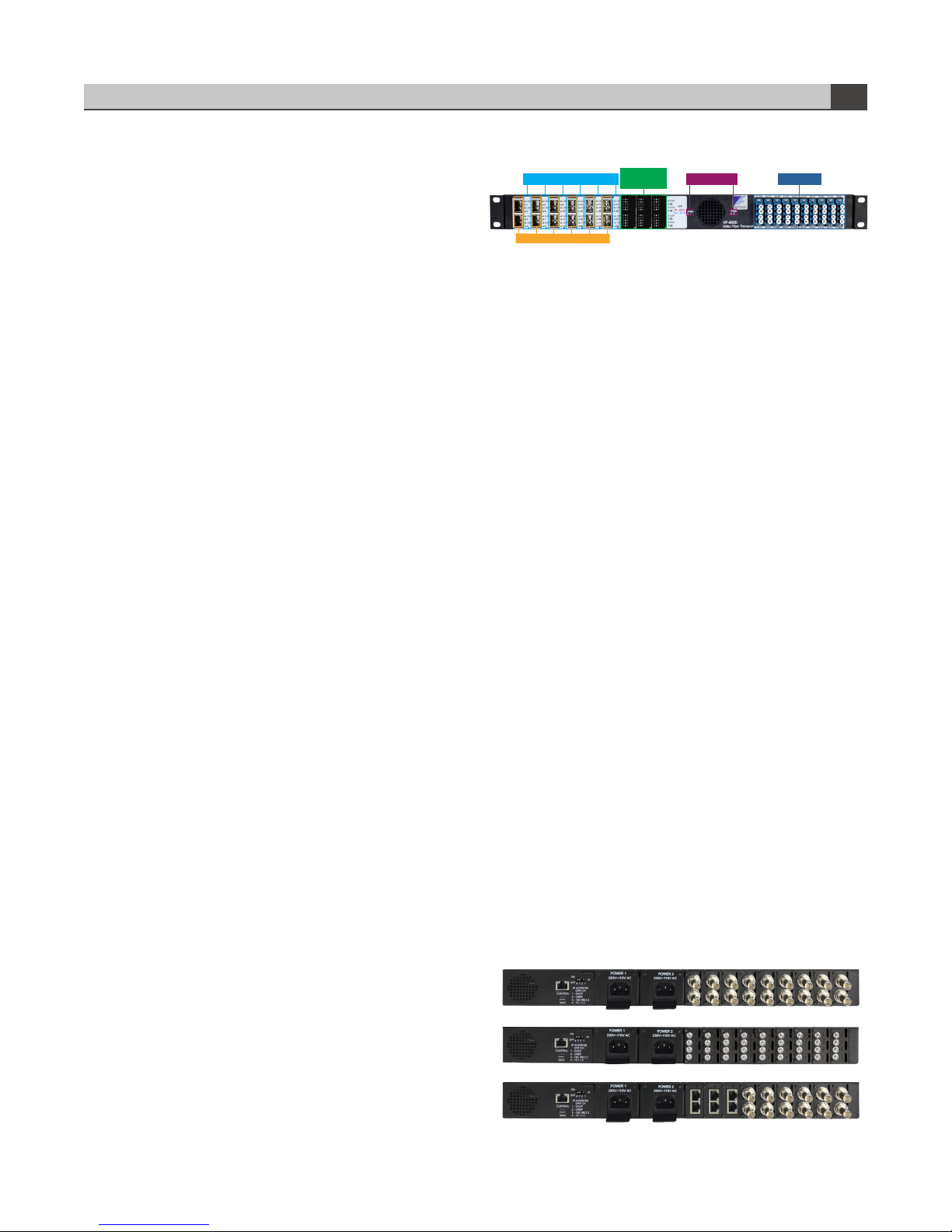
FRONT PANEL
CHANNEL STATUS INDICATORS POWER LED 1 & 2
SFP SLOTS
EMPTY SLOTS
COVERED
VF-9000 front
CWDM PORTS
The front panel of the quad BNC VF-9000 has a maximum
of 9 slots OR 36 SDI channels for SFPs and can be ordered
as per requirement. Each SFP slots has 2 channels. Each
channel has 2 LEDs indicating lock and channel direction.
The unit contains 40 LC ports for 36 CWDM cassette IO
connections, 2 common IO from multiplexed signals and 2
spares. The CWDM is inside the box. This makes the overall
design robust and avoids damage to the cassette’s fiber.
There are 2 power led that lights up green when the power
adapters are plugged and red if there is a brick failure.
The lock LED is a bi-color LED. It is Red when there is no
signal or when the signal does not lock to any data rate like
SD, HD or 3G. When the signal is locked to a particular data
rate the lock led changes color from Red to Green.
The channel direction led is a bi-color LED. It is either Blue or
Red. It lights up red when the optical port is in transmit mode
and lights up blue when the optical port is in receive mode.
The LED changes color based on the SFP installed.
There are 2 bi-color LEDs which light up green when both
the AC inputs are powered up with AC input. When ordered
with SNMP mode, in case of a power supply failure the LEDs
will light up red. If the system was ordered without SNMP
during a power supply failure the led will turn o.
In case of a dual BNC card front panel, the bottom SFP hole
will not be accessible and covered. The system will need to
go a factory upgrade if the box needs to change from a quad
BNC to dual BNC card or vice versa.
REAR PANEL
VF-9000 - Dual BNC
VF-9000 - HD-BNCs
VF-9000 - Dual Video BNC/Ethernet
Page 5

Instruction Manual, VF-9000 Series FEATURES & OPERATION 2
The Rear panel has 2 AC power entry with IEC 60320-1
connector. There is an Ethernet RJ45 port for connecting
to the frame controller via IP. There is a micro USB port for
updating the firmware for the frame controller. There is a
DIP switch for setting the IP address. There are BNCs and
bi-color LED lights for each BNC.
Power 1 is the main supply and Power 2 is the redundant
power supply. The system can be powered up by either one
of the power supply. The system powers up through the first
port plugged into the system. The second one can also be
plugged in simultaneously. In case of failure of Power1, then
the Power2 will take over the system or vice versa.
Each BNC has its own channel direction LEDs. The LEDs can
light up as red or blue based on the SFP plugged into the
front. When the LEDs are red it means the BNC is transmitting
video over copper. If the LED is lit up blue it will receive video
over copper. When ordered with regular BNCs they light up
green when the signal is locked and turns o when a signal
is not present.
VIDEO CARD
Quad Video
A combination of a dual transmits SFP and a dual receive
SFP can be used to configure the boards. Below is a diagram
showing signal flow for dierent SFPs. Each card has a fan
mounted on it. The fan pulls the air in from the front and then
blows it out through the rear. Each fan has a sensor and a fan
failure is reported over SNMP.
Signal flow (the arrow marks point based on the SFP installed)
Dual BNC card
Dual BNC
The dual BNC has 2 channels. The dual BNC card configures
itself based on the SFP inserted. Each channel is re-clocked.
There is a green LED on top of every BNC on the dual BNC
card. It shows if the signal is locked and a presence of a
signal in that channel. When a single TX SFP is installed the
CH2 BNC is an input and CH1 BNC is a re-clocked loop out
of the signal and the signal is outputted over fiber. When a
single RX SFP is installed the CH1 BNC and CH2 BNC both
are re-clocked outputs.
Video Card
The video cards are 4 channel cards. They can be ordered in
2 options based on the data rate required:
1. 3G option
2. 12G option
The video cards can be installed with a single\dual
transmitter or single\dual receiver SFPs only. The SFPs have
to be NON-MSA and SDI video. The SFPs can be dual TX, dual
RX, single TX and single RX. When a transmit SFP is installed
the board configures to receive video over copper and
transmit over fiber. So the video is equalized and re-clocked
before transmitted over fiber. In receive configuration, they
are received over fiber and re-clocked and transmitted over
copper. The video cards have High-density BNC on the rear
and hot-swappable SFP ports in the front. Each video card
has an assigned Slot ID and can transmit status information
over Ethernet. Each video stream can support quad SDI
streams and data rate up to 3Gbps. So an individual card
can support a 4k stream.
Add or remove a card
There are 9 slots in the VF-9000 frame. The system can
be upgraded or a card can be replaced by removing the
individual back panel. There is a removable back panel for
every single card. The back panel is held by 2 screws as
shown in Figure5. Remove the 2 screws and slide out the
card holding the BNC. Once removed slide in the new card
and push it till you hear a clicking sound. The sound signals
the card has mated to the front connector in the front panel.
Then power the device after installing the screws.
NETWORK SETTINGS & STATUS MONITORING
You can monitor the status of all the cards in your VF-9000
frame via a Web page dashboard that is embedded within
the frame. The steps for connecting to your facility’s Ethernet
network will depend on the network requirements of your
facility. Contact your IT Department before connecting to
your facility network to ensure that there will not be any
conflicts.
Page 6

Instruction Manual, VF-9000 Series FEATURES & OPERATION 3
Network Settings
The method for setting the IP address of the VF-9000 frame
is determined using the 4-position DIP switch on the rear
of the chassis. The four possible settings for IP address
configuration are outlined below:
• Preset IP address configuration — the network controller
card in the frame can be forced to use one of two specific
predefined IP address settings. This can be used to establish
initial communications, configure the frame for future
deployment on another network, or to override a custom
user configuration.
• User-defined IP address configuration — the network
controller card in the frame can be configured to use a userdefined static IP address from the device’s embedded Web
page. Re-configuration can only be done once network
communications have been established.
• Automatic configuration using DHCP — the network
controller card in the frame is configured to automatically
obtain network settings from a Dynamic Host Configuration
Protocol (DHCP) server. This method would be recommended
for advanced users only as there is no way to display the
DHCP assigned address on the frame itself.
The physical DIP switching settings are shown below. Only
one switch is allowed to be in the ON position (UP).
DIP SWITCH # DESCRIPTION
1
2
3
4
DHCP. Network settings assigned by a DHCP server
User IP Address. IP Address is set by the user through
the embedded Web page.
Fixed IP Address #1 - 192.168.2.2
Fixed IP Address #2 - 10.1.1.2
DIP SWITCH SETTINGS
Note — The IP Addresses of the VF-9000 frame and your
computer must be on the same Subnet. For example, if
the VF-9000 frame has an IP Address of 192.168.2.2, then
your computer should be configured for an IP address of
192.168.2.X where X is a number other than 2.
IP address DIP switch
To use one of the fixed preset IP addresses:
1. Set the DIP Switch to specify the desired preset IP address
as outlined in the IP address DIP switch table.
2. Ensure the network settings of your computer are
compatible with those chosen for the VF-9000 frame. Both
your computer and the VF-9000 must be on the same subnet.
Contact your IT Department if you need help determining or
configuring the network settings of your computer.
3. To prevent any possible IP address conflicts, initially
isolate the VF-9000 frame and your computer from the rest
of your network.
• If you are using a hub or switch, unplug all devices
except the VF-9000 frame and your computer
Or
• Connect the VF-9000 frame directly to your computer
with an Ethernet cable.
4. Launch a web browser on your computer.
5. Power up the VF-9000 frame.
6. In the address bar of the web browser, enter the preset
IP address selected on the DIP switch.
7. Wait approximately 30 seconds while the frame
establishes network communications.
8. Verify that the VF-9000 Dashboard Web page displays in
the web browser.
9. Should the Web page fail to display after a minute or two:
• Click the refresh/reload button in your browser.
• Verify the Ethernet cables are properly connected.
• Check the link/activity LEDs found on the Ethernet
RJ-45 connectors.
• Verify that you have properly performed each step of
this procedure.
• Contact MultiDyne Technical Support if you cannot
establish a connection.
To use a Custom User IP Address via Web page Dashboard:
Once network communications have been established
with a VF-9000 frame, a custom static IP address can be
configured through the Frame Ethernet Settings box in the
Web page Dashboard.
To configure the User IP address using the Web page
Dashboard:
1. Establish Ethernet communications with the VF-9000
frame using one of the preset IP addresses, DHCP, or
previously configured User IP address and load the device’s
Dashboard Web page in a web browser by entering the IP
address in the browser’s address bar.
2. In the Frame Ethernet Settings Box, enter the desired User
IP address in the User IP boxes.
Page 7

Instruction Manual, VF-9000 Series FEATURES & OPERATION 4
3. Ensure the new network settings chosen for the VF-9000
frame are compatible with the network the VF-9000 is to
be employed in. The computer used for monitoring the VF9000 frame must be on the same subnet. Contact your IT
Department if necessary.
4. Verify the IP address entered is correct and then click
the “Save IP” Button. This IP address will be stored in nonvolatile memory on the frame controller card.
5. The new IP address will not take eect until the IP Address
DIP switch is changed to the User IP address position. If the
DIP switch is already in the User IP position, a toggle of the
User IP position switch from o to back on again may be
required for the new address to take eect.
6. Enter the new IP address in the address bar of a web
browser and hit enter to verify the new IP address.
Web page status monitoring
You can monitor the status of all the cards in your VF-9000
frame via a Web page dashboard that is served from the
network controller card within the frame. This Web page is
accessed through any web browser by simply entering the
IP address of the frame in the address bar. Shown below is a
screen capture of the Web page from Internet Explorer.
Ethernet settings box on web page
To use DHCP to automatically assign network settings:
Network settings for the VF-9000 frame may be
automatically configured via a DHCP server on the
facility network. This method would be recommended
for advanced users only as there is no way to display
the DHCP assigned address on the frame itself.
To configure the network settings via DHCP:
1. Connect the VF-9000 frame to your network using an
Ethernet cable.
2. Power up the VF-9000 frame.
3. Set the DIP Switch position 1 to ON to specify DHCP
configured settings.
Physically identifying a VF-9000 frame in a facility:
On the rear of the chassis, there is an ID LED which can be
used to help identify the location of a particular VF-9000
frame. The Frame ID LED button in the Ethernet Settings Box
of the Web page allows you to turn this LED ON or OFF. When
turned ON, the LED on the chassis will blink.
The Web page is grouped into two areas. At the top is a
box that contains the frame’s current network settings
information. Below that, there are individual boxes which
display the information pertaining to the video cards that are
installed in the chassis.
Rear panel showing network settings and ID LED
Page 8

Instruction Manual, VF-9000 Series FEATURES & OPERATION 5
Ethernet Settings Box
Shown below is the Ethernet Settings Box on the Web page,
which contains the network settings information for the
frame. Also in this box are some controls to set a custom
IP address and a text box to enter a description or location
information of the frame.
Ethernet settings box on Web page
Card Slot Information
Following the Ethernet Settings Box on the Web page is the
card information for each slot in the chassis. The information
for each slot is contained within its own individual box for
easy identification. Slots which are not populated with a
card will show blank information.
The second table in a Slot Information Box displays the
information about the video signals that are present on the
card. The table is organized in rows with respect to the BNC
connectors which are numbered 1 to 4 from top to bottom
on the card.
Each BNC can be either an SDI Input or SDI Output depending
on the types of SFP Modules that are plugged into the card.
The direction is automatically configured when the SFP is
installed. The direction of each BNC is shown, followed by
the Video Data Rate and Signal Lock information. Following
that is the Optical Power, transmitted or received, and the
Optical Port the BNC is associated with. Optical ports are
numbered 1 to 4 from top to bottom on the card. If the BNC is
an Input, the Optical Power shown is the Transmitted Power
onto the fiber. If the BNC is an output, the Optical Power
shown is the Received Power from the fiber.
BNC Direction Rate Lock
Ch 1 SDI In Unlocked -1.48 dBm 2
Ch 2 SDI Out Unlocked -40.00 dBm 3
Ch 3 SDI Out Unlocked -40.00 dBm 4
Ch 4 SDI In Unlocked -2.07 dBm 1
Video information table
Optical
Power
Optical
Port
ELECTRICAL CHARACTERISTICS OF THE CARDS
Card slot information box on Web page
At the top of each Slot, Information Box is the Slot number,
followed by the type of card that is installed in the slot and
its software revision (if applicable). If a slot is empty, the card
type and revision information will be blank.
The first table in a Slot Information Box displays the
information about the SFP modules that are plugged into the
SFP Cages on the card. Displayed are the SFP Module type
and current operating temperature of each SFP in degrees
Celsius. Cages which are empty will show blank information.
SFP Type Temperature
Top Dual TX 51
Bottom Dual RX 45
SFP information table
V in (V) I in (A) Power (W) Configuration
12 0.22 2.64 No SFP’s Installed
12 0.29 3.48 1 Dual TX SFP Installed
12 0.33 3.96 2 Dual TX SFP Installed
12 0.34 4.08 1 Dual RX SFP Installed
12 0.4 4.8 2 Dual RX SFP Installed
12 0.36 4.32
1 Dual Rx and 1 Dual TX SFP
Installed
SNMP MONITORING
SNMP System Overview
The Network Controller Card can provide optional support
for remote monitoring of your VF-9000 frame using the
Simple Network Management Protocol (SNMP). This protocol
is compatible with many third-party monitoring and control
tools.
The SNMP agent running in the frame will accept SNMP
requests on the default SNMP port (161), using SNMP version
1. The SNMP Agent will send SNMP Traps to a notification
target, with user-configurable IP address and port number.
Page 9

Instruction Manual, VF-9000 Series FEATURES & OPERATION 6
The VF-9000 system parameters that are available for
monitoring through SNMP are defined by a series of MIB
(Management Information Base) files that must be loaded
into the management system. These MIB files define and
structure the parameters logically in a tree hierarchy format
system-frame-card.
For a complete list of VF-9000 parameters that can be
monitored using SNMP, refer to the MIB files for your system.
SNMP Configuration
The SNMP monitoring feature of the VF-9000 must be
configured through the Web page Dashboard in order for
Traps to be sent to the proper monitoring station. By default,
Traps are disabled until a valid station IP address and port
number are entered.
To enable SNMP Trap support using the Web page:
1. Ensure that you have configured the network settings for
your VF-9000 frame as outlined in the“Network Settings”
section of this manual.
2. Open the VF-9000 Web page Dashboard in a web browser.
3. In the SNMP Settings Box, check the Trap Enable check
box.
4. In the SNMP Settings Box, enter the IP address and Port #
for the SNMP Manager system that will be used to monitor
the Traps.
5. In the Frame Ethernet Settings Box, click the Save Button
to send and save this information in the frame.
• Frame Controller MAC address
• Frame Controller IP address
• Number of active card slots in frame
• Frame PSU1 status
• Frame PSU1 voltage
• Frame PSU2 status
• Frame PSU2 voltage
• Frame Fan status
Card Parameters:
• SDI Card Software version
• SDI Card SFP1 Type
• SDI Card SFP1 Temperature
• SDI Card SFP2 Type
• SDI Card SFP3 Temperature
• SDI Card Ch 0 SDI signal status
• SDI Card Ch 1 SDI signal status
• SDI Card Ch 2 SDI signal status
• SDI Card Ch 3 SDI signal status
• SDI Card Ch 0 SDI signal optical power status
• SDI Card Ch 1 SDI signal optical power status
• SDI Card Ch 2 SDI signal optical power status
• SDI Card Ch 3 SDI signal optical power status
• SDI Card fan status
The following is a list of the VF-9000 System SNMP Traps
that are sent to the SNMP Management software.
Frame Traps:
• Power Supply 1 status alarm: insertion, removal, failure, OK.
• Power Supply 2 status alarm: insertion, removal, failure, OK.
• Chassis Fan status alarm: failure, OK.
SNMP settings
System Parameters and Traps
The following is a condensed list of the VF-9000
System Parameters that may be monitored by the SNMP
Management software. For a complete list of parameters
that can be monitored, please refer to the MIB files for your
system. As of the time of this writing, the only type of plug-in
cards supported by the VF-9000 frame is the VBC2-3G Quad
SDI I/O cards.
Frame Parameters:
• Frame Name
• Frame Controller Software version
Card Traps:
• Card insertion, removal.
• Ch 0 SDI signal status change alarm: loss of signal, rate
change, rate lock.
• Ch 1 SDI signal status change alarm: loss of signal, rate
change, rate lock.
• Ch 2 SDI signal status change alarm: loss of signal, rate
change, rate lock.
• Ch 3 SDI signal status change alarm: loss of signal, rate
change, rate lock.
• SFP1 status change alarm: insertion, removal,
over-temperature alarm, temperature OK.
• SFP2 status change alarm: insertion, removal,
over-temperature alarm, temperature OK.
• Card fan status alarm: failure, OK.
Page 10

Instruction Manual, VF-9000 Series FEATURES & OPERATION 7
The following is the list of the MIB files that are required
to be installed on the SNMP Management system for a VF9000 system with VBC2-3G plug-in cards. Please contact
MultiDyne to obtain the most current versions of these files.
“MULTIDYNE-MIB.mib”
“VF-9000-MIB.mib”
“VF-9000-FRAME-MIB.mib”
“VF-9000-NODE-MIB.mib”
“VF-9000-GENERIC-CARD-MIB.mib”
“VBC2-3G-CARD-MIB.mib”
Basic Testing
SNMP Management Systems vary greatly in complexity,
capabilities, and cost. Operation of these systems is beyond
the scope of this manual but basic SNMP operation can
be verified using the de-facto Open-Source tool in every
Networking professionals toolkit: Net-SNMP. It is included
with most Linux distributions and is also available as a free
download for Windows http://www.net-snmp.org.
vf9000FrameObjects(1) vf9000FrameHardwareTable(3)
vf9000FrameHardwareEntry(1) 3 }
Now an actual frame can be queried to obtain parameter
information. Below are some Net-SNMP command line
examples:
To “Walk” the entire VF-9000 Frame
(replace 192.168.1.249 with the IP Address of the frame, if
necessary):
snmpwalk -m ALL -Os -c public -v1 192.168.1.249 vf9000
To do the above, but send the output to a text file:
snmpwalk -m ALL -Os -c public -v1 192.168.1.249 vf9000 >
C:\temp\vf9000snmpwalklog.txt
To Walk just the VBC2 cards installed in the Frame
(replace 192.168.1.249 with the IP Address of the frame, if
necessary):
snmpwalk -m ALL -Os -c public -v1 192.168.1.249
vbc2G3CardMib
To get the voltage of Power Supply #1 in the frame:
snmpget -m ALL -Os -c public -v1 192.168.1.249
vf9000PSU1Voltage.1
With Net-SNMP installed on a PC or Linux computer, copy
all the VF-9000 system MIB files listed above to the default
MIB directory used by Net-SNMP which is typically either
$HOME/.snmp/mibs or /usr/local/share/snmp/mibs
To test that the VF-9000 MIBs are installed in the correct
folder(s), open up a command line window and type the
following at the prompt:
snmptranslate -IR -Td -On VF-9000-FRAME-MIB::vf9000PSU1Voltage
The following response should be returned if the MIBs are
loaded properly on the computer:
.1.3.6.1.4.1.27334.2.1.2.1.3.1.3
vf9000PSU1Voltage OBJECT-TYPE
– FROM VF-9000-FRAME-MIB
SYNTAX Integer32
MAX-ACCESS read-only
STATUS current
DESCRIPTION “The PSU1 voltage in mV.”
::= { iso(1) org(3) dod(6) internet(1) private(4)
enterprises(1) multidyne(27334) vf9000(2)
vf9000Objects(1) vf9000FrameMib(2)
To get the temperature of SFP #1 on card #2 in the frame:
(for other cards, replace the last # with the slot #)
snmpget -m ALL -Os -c public -v1 192.168.1.249
vbc2G3SFP1Temperature.2
DC INPUT MONITORING
DC input monitoring is done in every box individually. There
is a voltage monitor circuit on the frame controller. This will
in return report the status of the power input and the status
of the frame fan over SNMP or the IP interface as ordered by
the customer.
Status Voltage
Power Supply 1 PS1 OK 11.98
Power Supply 2 PS2 OK 11.94
Chassis Fan OK
Power monitoring
Page 11

Instruction Manual, VF-9000 Series TECHNICAL SPECIFICATIONS 8
Technical Specifications
Digital Video
Video Connectors BNC or HD-BNC
Number of copper inputs or outputs up to 18 BNCs or up to 36 HD-BNCs
Interface SMPTE 424M, 297M, 292M, M259M-C, DVB-ASI
Input Coax EQ 3 Gbps: 12OM
1.485 Gbps: 240M
143-260 Mpbs: 450M
Input level 100mV (peak to peak)
Impedance 75 Ohms Bit-error
Rate 10-12
Return Loss >15 dB at 5 MHz - 1.485 GHz >10 dB up to 3 GHz
Mechanical, Environmental
Overall Dimensions (LxWxH) 19”L x 7.5”W x 1.75”H (Standard Frame)
Module Capacity 9 SFP modules (VF-9000-18-BNC or 18 SFP modulars “VF-900-36-MBNC”
Temperature Range -25 to 50°C FAN
Power
Power Supply Configuration Dual Internal power supplies
Voltage AC input 100-240V~47-63Hz 1.1A max
Maximum Power Consumption 25 watts (fully loaded frame with all accessories)
Note: Power consumption dependent on SFP type
Connectors C13 line chord
Status Indicators Power LEDs and Data Rate indicators
Page 12

10 Newton Place
Hauppauge, NY 11788
(800)-488-8378 / (516)-671-7278
sales@multidyne.com
www.multidyne.com
 Loading...