

Page 1

SMPTE HUT Manual 10/15/2014
Multidyne Electronics Inc.
24/7 Support: 516-238-4752
Hybrid Universal Transceiver
SMPTE Hybrid Cable Elimination System for
Broadcast Camera Systems
Product Manual
1
Page 2

SMPTE HUT Manual 10/15/2014
Multidyne Electronics Inc.
Important Safety Instructions
WARNING: To Reduce The Risk Of Fire Or Electric Shock, Do Not Expose This
Apparatus To Rain Or Moisture. The apparatus shall not be exposed to
dripping or splashing. Objects filled with liquids, such as vases, should not be
placed on the apparatus.
1) Read these instructions.
2) Keep these instructions.
3) Heed all warnings.
4) Follow all instructions.
5) Do not use this apparatus near water.
6) Clean only with dry cloth.
7) Do not block any ventilation openings. Install in accordance with the
manufacturer's instructions.
8) Do not install near any heat sources such as radiators, heat registers, stoves, or
other apparatus (including amplifiers) that produce heat.
9) Do not defeat the safety purpose of the polarized or grounding-type plug. A
polarized plug has two blades with one wider than the other. A grounding type plug
has two blades and a third grounding prong. The wide blade or the third prong are
provided for your safety. If the provided plug does not fit into your outlet, consult an
electrician for replacement of the obsolete outlet.
10) Protect the power cord from being walked on or pinched particularly at plugs,
convenience receptacles, and the point where they exit from the apparatus.
11) Only use attachments/accessories specified by the manufacturer.
12) Use only with the cart, stand, tripod, bracket, or table specified by the
manufacturer, or sold with the apparatus. When a cart is used, use caution when
moving the cart/apparatus combination to avoid injury from tip-over.
13) Unplug this apparatus during lightning storms or when unused for long periods
of time.
14) Refer all servicing to qualified service personnel. Servicing is required when
the apparatus has been damaged in any way, such as power-supply cord or plug is
damaged, liquid has been spilled or objects have fallen into the apparatus, the
2
Page 3
SMPTE HUT Manual 10/15/2014
Multidyne Electronics Inc.
apparatus has been exposed to rain or moisture, does not operate normally, or has
been dropped.
Introduction
The SMPTE HUT system enables you to replace long runs of the bulky and expensive
hybrid fiber cable that connects your camera and CCU with inexpensive fibers alone. It does
this by moving the camera power injection from the CCU side to the cam side. It consists of
a breakout adapter, known as the HUT-CCU, that attaches to the SMPTE connector on your
CCU. This enables you to connect 2 fibers going to the cam side using ST connectors, and
it also tricks the CCU into thinking that your camera is still attached by the hybrid fiber cable.
At the cam side of these fibers is the CAM HUT, which takes these 2 fibers with ST
connectors and routes them to a SMPTE hybrid fiber connector. It also plugs into local
mains power and injects 230 VAC for your camera into that same SMPTE connector which
now connects to the camera via a much shorter length of hybrid fiber cable. The CAM HUT
performs the same safety checks on this cable as your CCU does, and it optionally allows
remote powering down of your camera from the CCU side as well as optical repeating and
remapping of the wavelengths to and from the CCU.
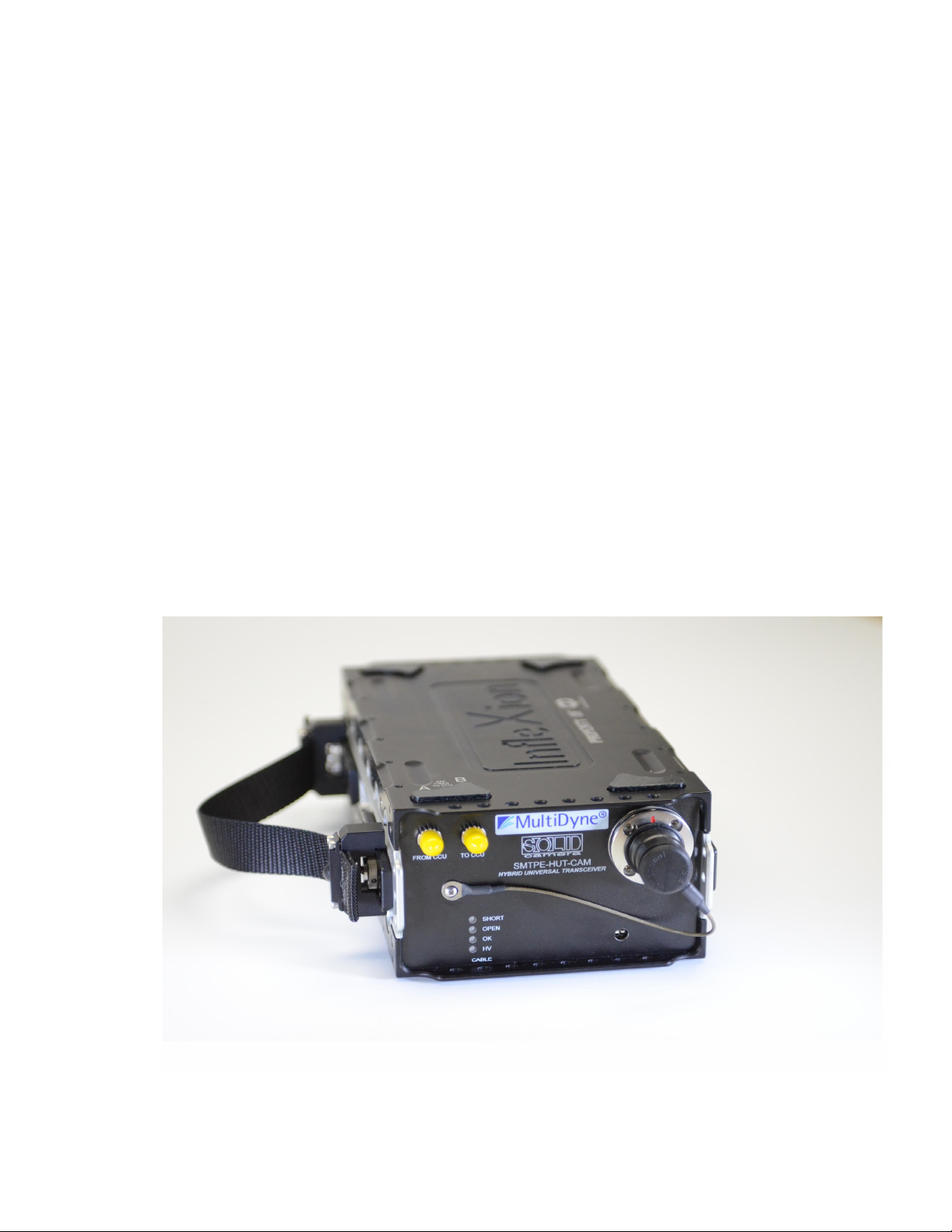
1. CAM HUT (cam side) unit
The CAM HUT basic version is shown in Fig. 1. There are 3 versions of the CAM HUT,
described below.
Fig. 1: CAM HUT
3
Page 4

SMPTE HUT Manual 10/15/2014
Multidyne Electronics Inc.
There are 3 versions of the CAM HUT, and each has its own front panel. These are shown
in Fig. 2. The basic configuration, which is the first panel, is to have the SMPTE hybrid fiber
connector to the camera and the 2 ST/UPC or duplex LC fiber connectors populated on the
front panel. These are labeled A and B.. Optionally, the optical connectors can be located
on the rear panel instead, as shown in Fig. 3. On some camera systems, A could mean
FROM CCU and B could mean TO CCU or vice-versa. In systems with the optional optical
repeater, it is important that the user be sure that his uplink and downlink signals are
matched to the proper connectors consistently throughout the link. In the basic system,
without optical repeating, it does not matter whether A or B is from the CCU or to the CCU,
since the fiber path is entirely passive. It only matters that, for a given direction, the same
label is used throughout the entire link.
The front panel of the basic unit has the following standard features:
RESET: This button resets a 2A thermal circuit breaker in series with the SMPTE hybrid
connector output. In the event of an overcurrent fault that causes power to the cam to be
removed, as evidenced by the HV PRES LED being dark, and the button popped out.
Pressing this button restores power after the fault is removed. Note that RESET does not
restore functionality if a SMPTE cable fault exists.
SMPTE CABLE Status LEDs:
SHORT glows red upon short or leakage of hybrid fiber cable to ground. Upon power up,
this LED may glow red for a few seconds even if no short exists. This is normal.
OPEN glows red when cable is open or cam not connected. If using a Hitachi camera, be
sure to set the CAM TYPE switch to the Hitachi position, to bypass the OPEN cable test.
Otherwise, it will always fail. For Sony or Ike, set switch for those cameras.
OK glows green indicating a properly connected hybrid fiber cable.
HV ENAB glows green when the HUT attempts to apply 230VAC to the hybrid fiber cable.
This occurs only after all cable checks have been completed successfully.
HV PRES glows green when 230VAC is actually present on the hybrid cable. If HV ENAB is
green but HV PRES is off, check to see if the circuit breaker has been tripped. If so, the
RESET button may need to be pressed after removing the fault. Otherwise, there could be a
failure of either the HUT relays or power transformer, and the HUT will require service.
CAM TYPE: Selects between Hitachi and Sony/Ikegami cameras.
4
Page 5

SMPTE HUT Manual 10/15/2014
Multidyne Electronics Inc.
Optional Front Panel Features:
If ordered with the optional Optical repeater, besides the features of the basic unit, the front
panel will have these additional features as shown in the second panel:
OPTical Status Leds:
There are 2 LEDs labeled A and B for the 2 optical fibers. Each glows red if the received
optical strength of its fiber is less than -18db, and green if greater.
REMOTE enable switch: Set to on to enable the Cam HUT to prevent HV from being
applied to the camera if fiber A is not illuminated. Fiber A is assumed to be the fiber
uplinking from the base to the camera. This effectively places the camera in standby, as
only standby voltage can be applied. If fiber A is illuminated, the Cam HUT will enable the
application of HV if all other cable checks have been passed. If the REMOTE switch is set to
off, this feature is bypassed and the application of HV will be determined by the cable
checks alone. Functionality will then be identical to the basic unit.
If ordered with the optional OLED display, the front panel will look like the third panel in Fig.
2. All the status LEDs for optical strength and cable status are deleted, and replaced with
the display, and a single STATUS LED. The STATUS LED is normally green, but if there is
a problem, such as a cable open or short, or insufficient optical signal, it glows red,
prompting the user to consult the display to determine the exact fault. The CAM TYPE
switch is also eliminated as it is now selected via the display menu.
The display will show a screen saver upon power up. After a few minutes, the screen will go
dark if the SELECT button has not been touched. If touched, the display will again become
active and will display status information. The SELECT joybutton is used to navigate the
display. Push on the upper or lower edges to choose between screens, once within a
screen, push the left or right edge to choose parameters within the screen, and push straight
in to select a parameter. Doing this exits you to the next screen. You can choose screens
showing cable status, optical signal status, and camera type, amongst others.
5
Page 6

SMPTE HUT Manual 10/15/2014
Multidyne Electronics Inc.
Fig. 2: CAM HUT front panels
6
Page 7

SMPTE HUT Manual 10/15/2014
Multidyne Electronics Inc.
The rear panel is shown in Fig. 3. This drawing shows an optional location of the optical
connectors on the rear. The same considerations concerning the fiber optic connectors
should be observed as on the front panel. Also on the rear is a fused, filtered power entry
module that accepts an IEC cord and a primary power switch. If the optical connectors are
located on the front panel as shown in Fig. 2, then the rear would be completely blank
except for the power entry. If pressing the RESET button after an overcurrent fault has
occurred does not restore power, please check the fuse.
Fig. 3: CAM HUT Rear Panel
7
Page 8

SMPTE HUT Manual 10/15/2014
Multidyne Electronics Inc.
2. Base (CCU side) Unit
The Base unit, known as HUT-CCU, has a SMPTE hybrid receptacle panel mount connector
for connection to the CCU and 2 ST/UPC or duplex LC connectors for the fibers to the CAM
HUT. The base unit is shown here in Fig. 4 with ST connectors As on the CAM HUT, the ST
or LC connectors are labeled either FROM CCU and TO CCU or A and B. The same
considerations concerning the fiber labels should be observed, as on the CAM HUT.
Fig. 4: Base Unit
The HUT-CCU acts as a breakout for the optical ports in the CCU SMPTE connector. It also
tricks the CCU into thinking a camera is attached by a SMPTE hybrid fiber cable. This is
necessary to enable the CCU to leave standby mode so that it can accept video from the
camera. It has 2 LEDs located on the panel with the ST connectors, labeled Power and HV.
The Power LED is green when the CCU is supplying power to the HUT-CCU, and the HUTCCU is attempting to spoof the CCU. The HV LED is green when the CCU is supplying high
voltage. This means that the HUT-CCU has successfully spoofed the CCU into thinking a
camera is attached. Otherwise, the CCU will not leave standby mode. The HUT-CCU comes
configured for use with Sony, Hitachi, or Ikegami CCUs. However, the Ike CCUs need to be
configured for “single fiber mode” to work with the HUT-CCU in its default configuration,
otherwise the Ike CCU will report an open cable and will not leave standby mode. Note that
the HV LED on the HUT-CCU will remain off in single fiber mode, even during normal
operation.
8
Page 9

SMPTE HUT Manual 10/15/2014
Multidyne Electronics Inc.
To avoid having to set the Ikegami CCUs for single fiber mode, you can configure the HUTCCU specifically for your Ike. To do this, one must open the HUT-CCU and set a dip switch
as follows:
Sony/Hitachi Ikegami
SW1 off on
SW2 off on
SW3 on off
SW4 off off
Either approach to enabling Ikegami CCU operation is valid. The choice is up to you,
although single fiber mode may make some camera system features unavailable.
Note that with some Sony camera systems, the CCU may report an open cable condition.
Despite this, the system will work normally, so you can safely ignore this warning.
3. Specifications
.
SDI Standards Supported, repeater SMPTE 259M/292M/297M/425M, DVB/ASI
SDI Added Jitter, repeater < .03 UI, < 1 MHZ
Laser Safety, repeater Class 1
Optical Connectors, CAM HUT SMPTE 311 Plug + 2 ST/UPC or LC
Optical Connectors, HUT-CCU SMPTE 311 Receptacle + 2 ST/UPC or LC
Optical Wavelengths, nm, repeater 1310. 1550 or CWDM optional
Optical Sensitivity, repeater -18 dBm
Optical Output Power, repeater -2 ~ -8 dBm
Fiber Optic cable length, standard Limited by camera/CCU
Fiber Optic cable length, repeater Up to 20km
Indicators, CAM HUT Unit, standard Cable open/short, HV/status
Indicators, CAM HUT Unit, repeater As above + optical power ok/bad/laserfail
Electrical Output, CAM HUT Unit 230VAC @ up to 250VA, active,
24VAC @ up to25VA, standby
Power Requirement, CAM HUT Unit 115/230VAC, 50/60HZ, 260VA
Power Requirement, HUT CCU Unit Steals power from CCU
Operating Temperature 0 to 70 deg C
Certifications FCC class A and UL/CE
Dimensions, CAM HUT unit 3.5” H x 5.5” W x 10.5” D
Weight, CAM HUT unit 10 pounds
Dimensions, Base unit 2.0” H x 2.5” W x 7.0” D
Weight, Base unit 0.5 pound
9
 Loading...