

Page 1

INSTRUCTION MANUAL
SilverBack II
CAMERA-BACK FIBER OPTIC TRANSCEIVER
191 FOREST AVENUE
LOCUST VALLEY, NY 11560-2132 USA
(800)-488-8378 / (516)-671-7278 FAX (516)-671-3362
sales@multidyne.com
www.multidyne.com
Page 2

MULTIDYNE, the Multidyne logo, X-X-FTX and X-X-FRX are registered trademarks of
MULTIDYNE Electronics, Inc.
Copyright 2009 MULTIDYNE Electronics, Inc., Locust Valley, New York. Printed in the United
States of America. All Rights Reserved. Contents of this publication may not be reproduced
in any form without the written permission of MULTIDYNE Electronics, Inc.
This product was designed and manufactured in the
UNITED STATES of AMERICA
-ii-
Page 3

TABLE OF CONTENTS
INTRODUCTION ..................................................................................................................... 1
FEATURES AND OPERATION ............................................................................................... 2
CAMERA UNIT .................................................................................................................... 3
CAMERA VIDEO .............................................................................................................. 4
RETURN VIDEO .............................................................................................................. 4
REFERENCE ................................................................................................................... 4
AUDIO .............................................................................................................................. 5
INTERCOM ...................................................................................................................... 6
DATA ................................................................................................................................ 6
TALLY AND GPIO ............................................................................................................ 7
BASE UNIT .......................................................................................................................... 8
CAMERA VIDEO .............................................................................................................. 8
RETURN VIDEO .............................................................................................................. 9
REFERENCE ................................................................................................................... 9
AUDIO .............................................................................................................................. 9
INTERCOM .................................................................................................................... 10
DATA .............................................................................................................................. 10
TALLY AND GPIO .......................................................................................................... 11
TIMECODE .................................................................................................................... 11
FIBER INPUT/OUTPUT .................................................................................................. 12
POWER REQUIREMENTS ................................................................................................... 13
JUICE POWER OPTION ....................................................................................................... 14
INSTALLATION ..................................................................................................................... 16
CAMERA UNIT .................................................................................................................. 16
GOLD MOUNT ............................................................................................................... 16
V-MOUNT ....................................................................................................................... 17
IRIS ROD MOUNT .......................................................................................................... 18
BASE UNIT ........................................................................................................................ 20
APPENDIX A. PIN-OUT SPECIFICATION ............................................................................ 21
CAMERA UNIT PIN-OUTS ................................................................................................ 21
BASE UNIT PIN-OUTS ...................................................................................................... 22
APPENDIX B. BLOCK DIAGRAMS ....................................................................................... 24
SILVERBACK II CAMERA SIDE BLOCK DIAGRAM (TRANSMITTER) ............................. 24
SILVERBACK II BASE UNIT BLOCK DIAGRAM ................................................................ 25
APPENDIX C. TECHNICAL SPECIFICATIONS .................................................................... 26
-iii-
Page 4
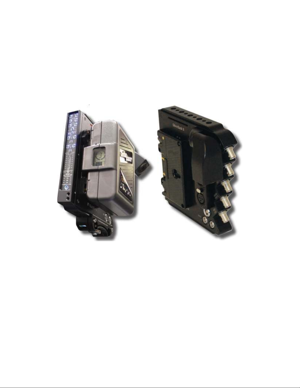
INTRODUCTION
Figure
1 - SilverBack II Camera
-
Back Fiber Optic Transceiver
The new SilverBack II provides users with an ergonomic and unobtrusive package, optimized
to deliver high-quality signals over long distances. This includes a full complement of bidirectional signals for most of the well-known digital camcorder brands in the market today.
The feature-rich, battery-powered system is truly an innovation for fiber transport. The
SilverBack II transports all camera signals including SDI video, audio, control data, GPIOs,
and tally for sports, ENG, D-SNG, and multi-camera studio applications over a single cable,
over any distance.
The product design has been refined to keep overall size and weight as small as possible
without sacrificing performance or operability. The elegant, compact case just over one-inch
thick combines with a simple and intuitive user interface is for ease of use.
With a collaborative effort, MultiDyne now provides camera operators with innovative new
solutions that are elegant in design while offering improved workflow and operational ease of
use.
The design of new high-performance, fiber-optic based camera accessories are to target a
wide range of applications — from broadcast television stations to 3D cinematographers.
The SilverBack II can also transport SDI video up to 3G HD-SDI uncompressed with
embedded or separate program audio. The return video option supports up to 3G HD-SDI
video for viewfinder or monitor viewing, providing a high-quality viewing experience for users
in the field.
In addition, this system allows users to achieve camera control/RCP paint functions through
one of the two available data channels, and an additional return video channel is available for
camera sync or genlock. Several options are available for optical connectivity including STs,
Neutrik® opticalCon, Fibreco Mini 2 expanded beam, and LEMO 304M.
-1-
Page 5

FEATURES and OPERATION
Milled from a solid block of aluminum, the SilverBack-II measures just over 1-inch thick, and
providing camera operators with a compact, unobtrusive camera-backed system for remote
signal transmission.
MultiDyne includes integrated dovetails on the top and bottom of the unit that you can use
with optional accessories, such as 15-mm iris rod adapters. This innovative feature is
extremely useful for the next generation of small-sized cameras that do not have professional
battery mounts or a method for shoulder use.
Refer APPENDIX A for Pin-Out details.
The following list shows SilverBack II features:
• All signals on ONE Cable
• Bi-Directional 3G-SDI
• 10km Operation
• Intercom with IFB/PGM inject
• Optional SDI Send for dual stream/3D
• 2 MIC inputs with phantom and pre-amps
• Accepts Anton-Bauer and “V-mount” Battery plates
• Integrated Tally lamps
• Camera RCP Control
• 1 additional Data path (232/422)
• 2 GPIO’s
• Integrated swivel for optical connector
• Top-mounted taps for mounting viewfinder
• Optional 15mm Iris Rod bracket for mounting flexibility
• Lightweight, low-profile packaging
-2-
Page 6
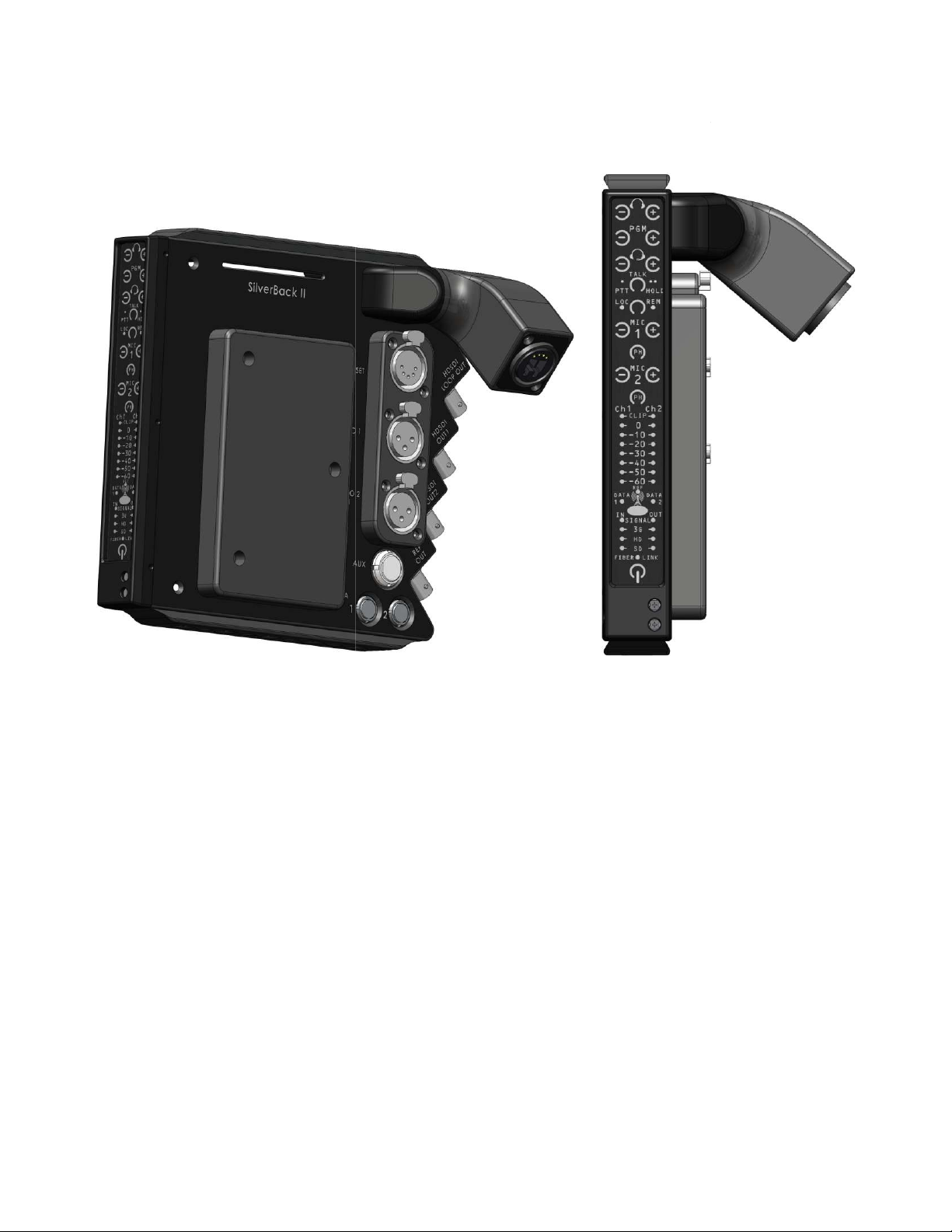
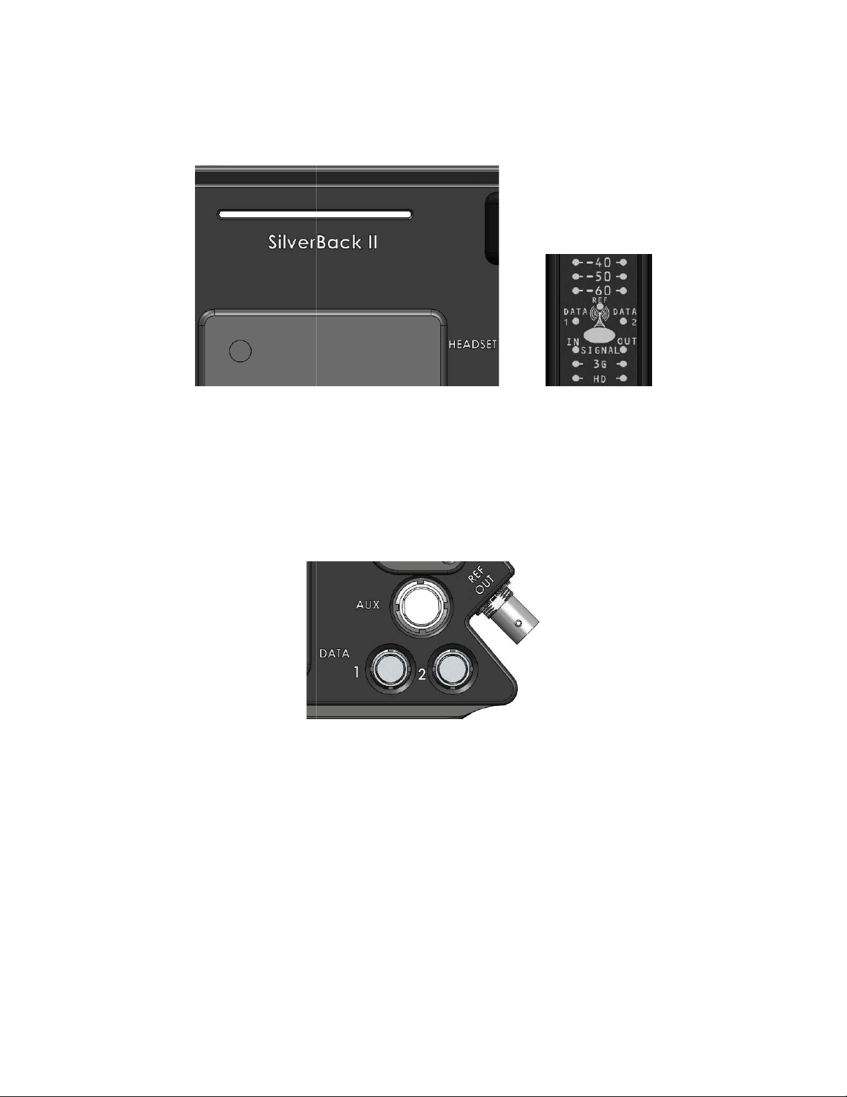
II system, the operator control panel provides a simple interface by which
the camera operator can quickly and easily check on system link, signal status, and adjust
uttons and blue LED backlighting make these adjustments fast and easy.
Figure
2 -
SilverBack II Camera Unit
CAMERA UNIT
In the SilverBack
audio and intercom levels.
Soft-touch b
-3-
Page 7
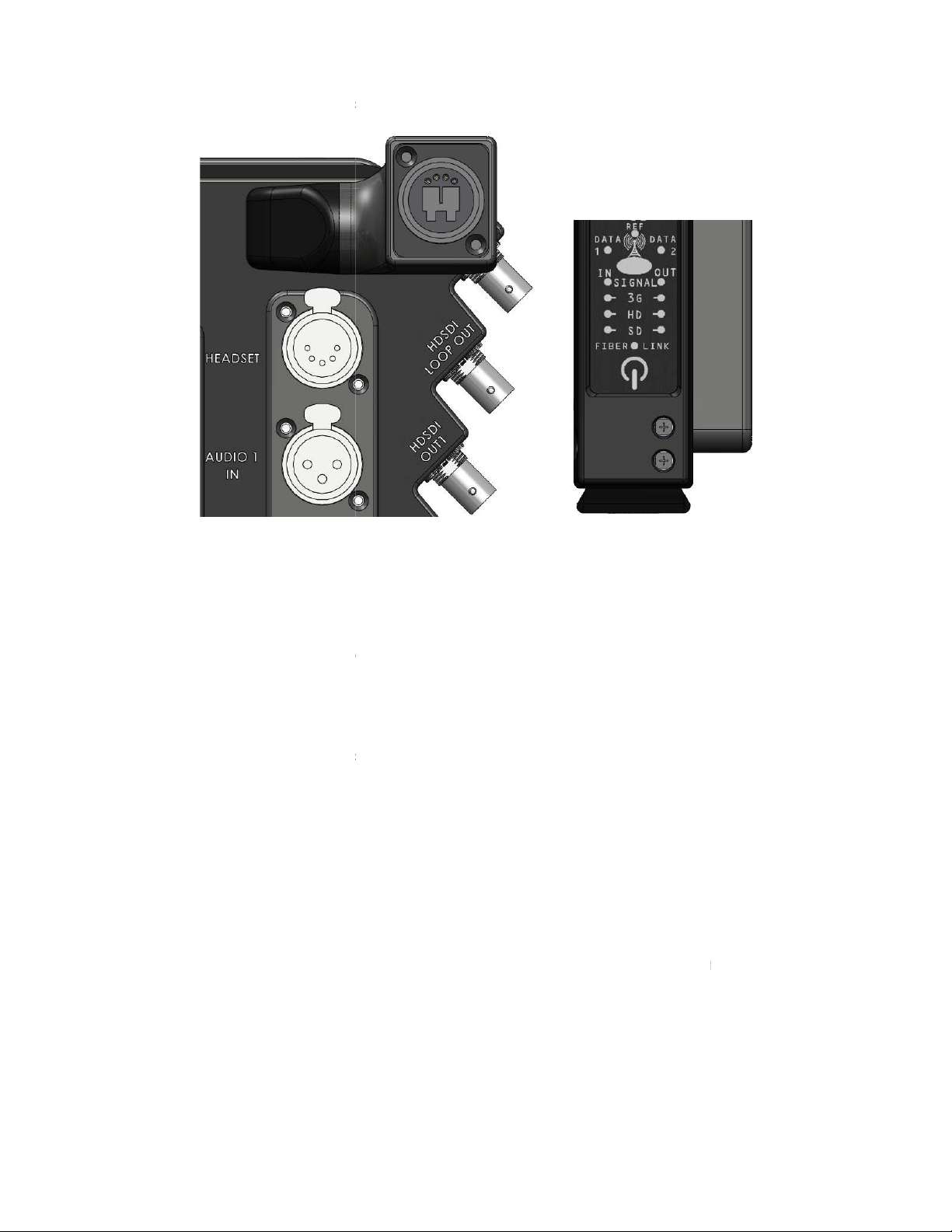
This section describes the details specific to SilverBack II camera video.
connected to BNC input 1, which is at the top of the unit. The
camera unit accepts all standard SMPTE video rates ranging from 19 Mbps to 3Gbps and
supports embedded audio. LED’s on the front panel indicate the video data rate.
output of the camera video. You can use this for local monitoring
This section describes the details specific to SilverBack II return video. You can use this
feature for viewfinder, prompter, and so on.
is transported to the camera unit and output on BNC 3. All standard
SMPTE video rates ranging from 19 Mbps to 3 Gbps are supported as well as embedded
audio. LEDs on the front panel indicate the video data rate.
nc output for genlocking a camera and supports Black Burst
Level sync signals. It is highly recommended that you use Tri
and Black Burst for SD video. Reference video is output on BNC 5 (bottom most).
Figure
Level sync for HD video
3 -
Camera Video Connectors and Status
CAMERA VIDEO
Video from the camera is
BNC 2 provides a loop-thru
purposes.
RETURN VIDEO
Video from the base unit
REFERENCE
SilverBack II has a reference sy
and Tri-
-
-4-
Page 8
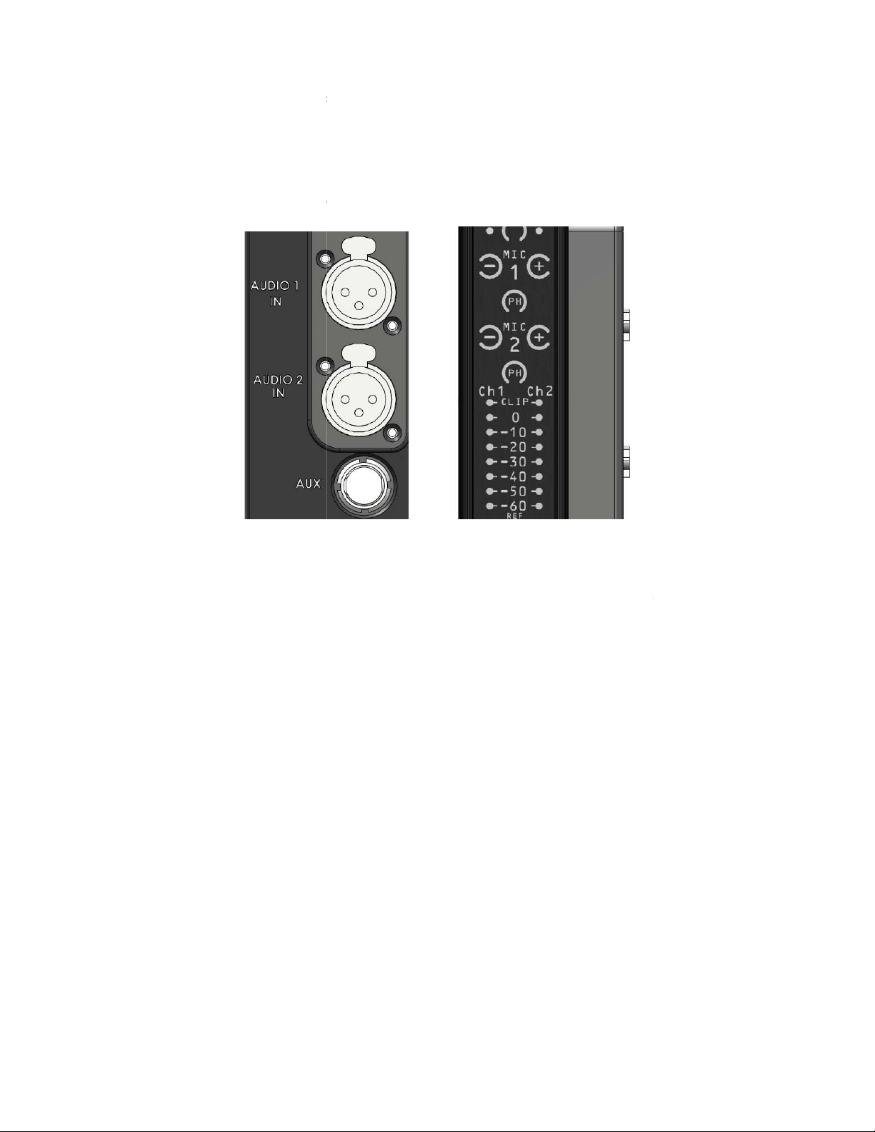
This section describes the details specific to SilverBack II audio.
There are two balanced MIC preamp channels available for microphones or other sources
that are associated with the camera.
Each MIC preamp channel features adjustable gain from 0 to 60 d
addition, each MIC input has selectable 48V phantom power.
buttons on the front panel are used to make adjustments to the gain. LED
n microphone VU level or gain selection when gain modified. To
turn the Phantom Voltage ON or OFF for a particular input, press and hold the desired PH
Out details.
Figure
B in 10 dB increments
4 -
MIC/Audio Inputs and Controls
AUDIO
. In
MIC 1 and 2 + indicators will display the mai
button for approximately 1 sec.
Refer APPENDIX A for Pin-
-5-
Page 9
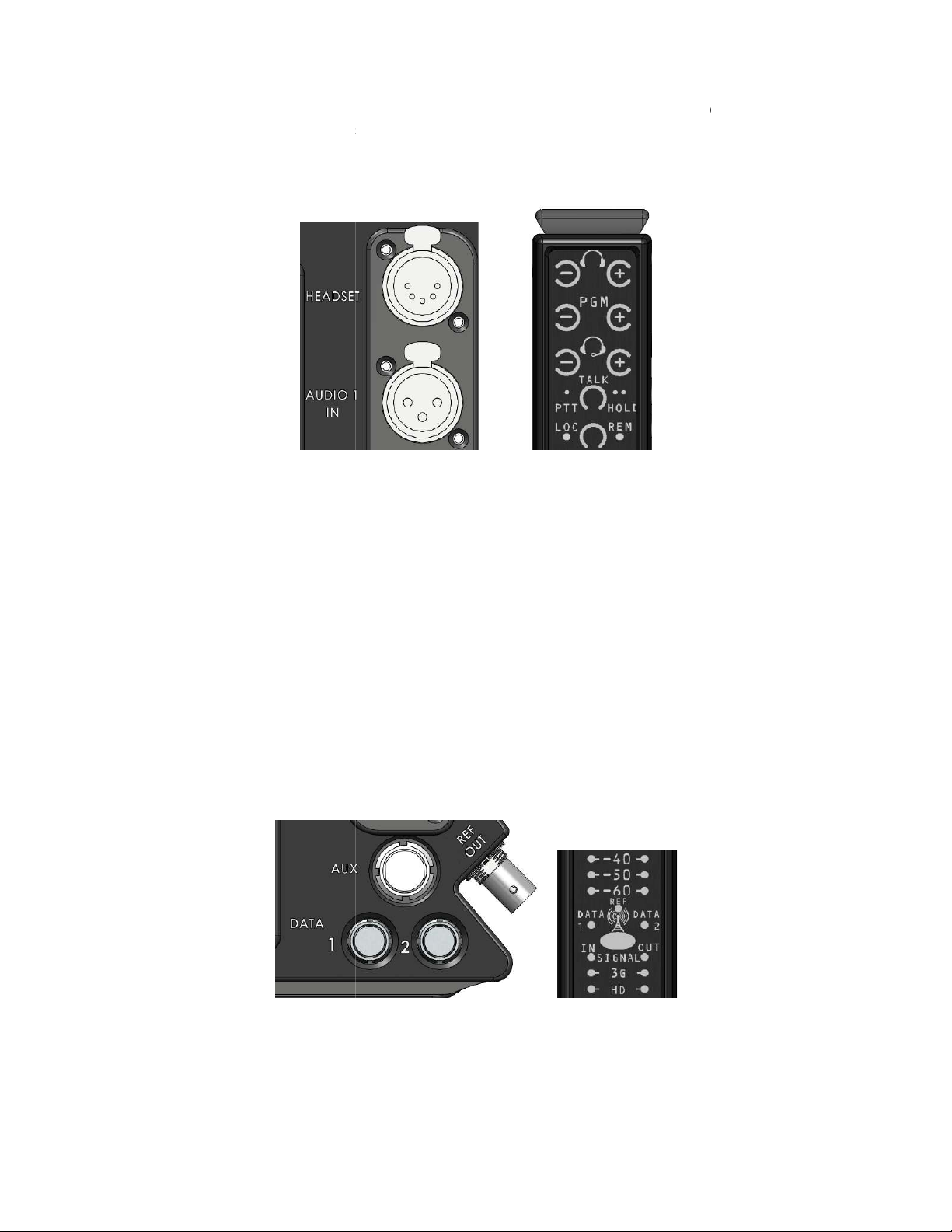
SilverBack II supports an intercom headset port with headphone mixer for program audio,
intercom audio. Intercom audio is output on the left headphone channel and program audio is
n the right channel. You can perform MIC gain and sidetone adjustments using recessed
trimpots at the bottom of the front panel. The headset uses a 5
A Local/Remote button on the front panel allows selection between the PTT switch on the
panel or a remote switch that can be used to open the intercom MIC. The selected switch’s
LED blinks when the MIC is open.
a headphone a
front panel
directional serial data communication
You can select RS232 or RS422 by either wiring Pin 4 to GND
LED’s on the front panel indicate data activity for DATA
Out details.
Figure
pin XLR connector.
mplifier for a talent earphone. This amp
from the
channels each with it
5 -
Headset Connector and Controls
Figure
6 –
Data Connectors
INTERCOM
o
-
In addition, SilverBack II has
an adjustable level through the
input at base.
DATA
SilverBack II supports two biown 7 pin LEMO connector.
or wiring it footing respectively.
channels 1 and 2.
lifier has
. The audio for this originates
PGM Audio
s
Refer APPENDIX A for Pin-
-6-
Page 10
II has two integrated Tally LED’s to indicate Tally status, a large bar at the rear of
the unit as well as on the front panel. In addition, a relay contact Tally output provided on the
pin LEMO connector labeled AUX.
X connector also provides two GPI’s and two GPO’s for user
well as Timecode input and output.
In addition, the AUX connector has an input to key the headset MIC. A closure to ground
Out details.
defined purposes, as
Figure
7 -
Tally
Figure
8 –
AUX Connector
TALLY AND GPIO
SilverBack
16-
The AU
activates this input.
-
Refer APPENDIX A for Pin-
-7-
Page 11

Figure
9 –
Silv
erBack II Base Unit
Figure
10 -
Camera Video
BASE UNIT
The SilverBack-II Base Unit is a one RU rackmount chassis that provides all the audio, video
and data I/O’s to and from the Camera Unit.
Refer APPENDIX A for Pin-Out details.
CAMERA VIDEO
The camera video output provides the SDI video output from the camera and supports all
SMPTE video rates up to 3Gbps including any embedded audio or data from the camera.
-8-
Page 12

Figure
11 -
Reference Input
Figure
12 -
MIC/Line Audio 1 and 2 Outputs
RETURN VIDEO
You can use this input to provide an SDI video signal back to the camera unit. Primarily, you
can use this with a viewfinder, prompter, and so on. The return video supports all SMPTE
video rates up to 3GBps as well as embedded audio.
REFERENCE
You can use the reference input to provide a reference signal to the camera for genlocking
purposes. SilverBack II supports Black Burst and Tri-Level sync signals. A Loop-Through
output is provided for connecting to additional equipment.
Note: It is highly recommended that you use Tri-Level sync for HD video and Black Burst for
SD video.
AUDIO
This section describes MIC/Line audio 1 and 2 outputs.
These XLR connectors provide the analog outputs from the corresponding inputs at the
camera unit. MIC/Line selection, as well as audio gain is set at the camera unit. You can set
the full scale (FS) output level from 0 dBu to a maximum of +24 dBu.
Refer APPENDIX A for Pin-Out details.
-9-
Page 13

Figure
13 -
Intercom Connection
Figure
14 -
Two Bi
-
Directional Data
Channels
INTERCOM
SilverBack II supports a 4-wire intercom connection to the camera unit. With the help of an
additional mono audio input, you can either send PGM audio back to the camera or use as a
Talent IFB channel.
The nominal audio input level for 4-wire intercom and PGM/Talent IFB is +4 dBu (+24 - dBu
max). MultiDyne provides audio level adjustments for these signals on the camera unit.
Refer APPENDIX A for Pin-Out details.
DATA
The SilverBack-II supports two bi-directional data channels from the base to the camera.
These channels are configurable for RCP/Paint control or other data communication
purposes as follows:
• RS232
• RS422
• TTL data levels
The custom RCP/Camera cable sets are available from MultiDyne for most mainstream
camera manufacturers. You can observe the data communication activity for each channel
through the front-panel LED’s.
Refer APPENDIX A for Pin-Out details.
-10-
Page 14

Figure
15 -
Tally and GPIO
Figure
16 -
Timecode Input and Output
TALLY AND GPIO
SilverBack II includes a dedicated Tally input to provide Tally indication at the Camera,
typically from a production switcher or Tally System. Connecting this input pin to Ground
activates the Tally Lamp and Tally output on the Camera Unit.
SilverBack II provides two additional GPI inputs for user-defined purposes and two GPO
outputs for user GPI signals initiated at the Camera Unit. These N/O relay contacts are
closed to ground when the GPI is activated. They are capable of handling 48V, and 1A.
Refer APPENDIX A for Pin-Out details.
TIMECODE
SilverBack-II includes a timecode input to provide to the camera. The timecode input is
unbalanced and handles levels up to 7Vp-p.
In addition, a timecode output is included to provide the timecode output from the camera to
other devices. The timecode output is unbalanced, 3Vp-p.
-11-
Page 15
Figure
17 -
SMPTE 304M
FIBER INPUT/OUTPUT
The SilverBack II transports all bi-directional signals using CWDM technology on a single
fiber. For this, a single-mode fiber is required.
In SilverBack II, the fiber optic connection is made at the rear of the base unit. Several
different connector types are available that includes, SMPTE 304M (as shown above),
Neutrik opticalCon Duo, Expanded Beam, ST, and LC.
-12-
Page 16

POWER REQUIREMENTS
The SilverBack-II mounts between a professional broadcast camera and its battery with your
choice of Anton-Bauer or “V-Mount” battery plates. Being only 1” thin and 2.5 pounds in
weight, the SilverBack-II will not significantly alter the total weight or the center-of-gravity of
the handheld camera. With SilverBack II’s energy-efficient design, power consumption is
minimal, as well.
If local power is available, you can use a local 12VDC supply with a 4-pin adapter plate
(Anton-Bauer part # SO-XLR) to power both the SilverBack II and the camera.
-13-
Page 17

Figure
18 -
SB Cam with Juice Front and Oblique View
JUICE POWER OPTION
You can power the Silverback II Camera Unit and Camera by the optional Juice Back power
system, and eliminate the need for a battery or local power supply. The Juice Back receives
its power from the SilverBack Base Unit using a hybrid fiber cable.
The Juice Back option is installed as an integral part of the SilverBack II Camera Unit,
replacing the standard rear cover plate. There are no additional external power cables to
connect and however, you may still use a battery in parallel.
The Juice Back power system can deliver up to 100W of power to the camera at distances up
to 1000 feet. Camera configurations, accessories, and the length and type of used Hybrid
fiber cable affect the amount of total power available at the camera.
-14-
Page 18

Figure
19 –
Juice Power
You can use the following chart as a guideline to determine whether a particular power and
distance requirement can meet with the Juice Back system. The trend line in the chart
indicates Gepco HDC 120P hybrid fiber cable.
The HUT-48, an external remote power supply option is also available that allows power to
be injected mid-span, rather than being supplied from the SilverBack Base Unit. This allows
greater flexibility in covering longer distance or higher power requirements. For instance, you
can run one km of standard ST fiber cable from the Base Unit to the HUT-48, which then
provides power to the camera for the last 150m on hybrid fiber cable.
-15-
Page 19

Figure
20 -
Gold Mount Sample
INSTALLATION
This section describes SilverBack II Camera and Base Unit installation.
MultiDyne supports the following installation types:
• Gold Mount
• V-Mount
• Iris Rod Mount
Gold Mount and V-Mount are different types of camera battery form factors for professional
video cameras. You can mount the SilverBack II camera unit directly on the back of a
professional video camera that has either of these two battery styles.
CAMERA UNIT
This section describes the various installation/mounting systems from the camera unit
perspective. The SilverBack II camera unit includes both the Male and Female battery mount
plates. When you mount cameras with either Gold Mount or V-Mount systems, the camera
unit mounts between camera and battery. The camera unit shares power from the battery
with the camera.
GOLD MOUNT
Gold Mounts are one type of camera battery form factor for professional video cameras.
Gold Mount locks into place to provide uninterrupted power to your camera by employing
three solid mechanical connections and self-cleaning, gold-plated communication pins.
-16-
Page 20

Figure
21 - V-
Mount Samples
Providing power requirements ranging from 7.2V to 28V, the Gold Mount System is the most
widely used battery mounting system by professionals in the industry. It is available as
factory standard equipment on many cameras from leading manufacturers.
V-MOUNT
V-Mounts are another type of camera battery form factor for professional video cameras.
They are versatile, affordable, and easy to use.
In this type, configurations with peripheral equipment, such as camera lights and hard disk
recorders are common and you can power by industry standard D-tap connectors on VMount plates.
-17-
Page 21

Figure
22 -
Iris Rod Mounting Camera Sample
-
1
IRIS ROD MOUNT
For camera systems without Gold or V-Mounts, or in situations, where SilverBack II cannot
be directly mounted to a camera, a dovetail accessory is available. This allows you to mount
the camera unit to a set of 15mm Iris Rods.
-18-
Page 22

Figure
23 -
Iris Rod Mounting Camera Sample
-
2
-19-
Page 23

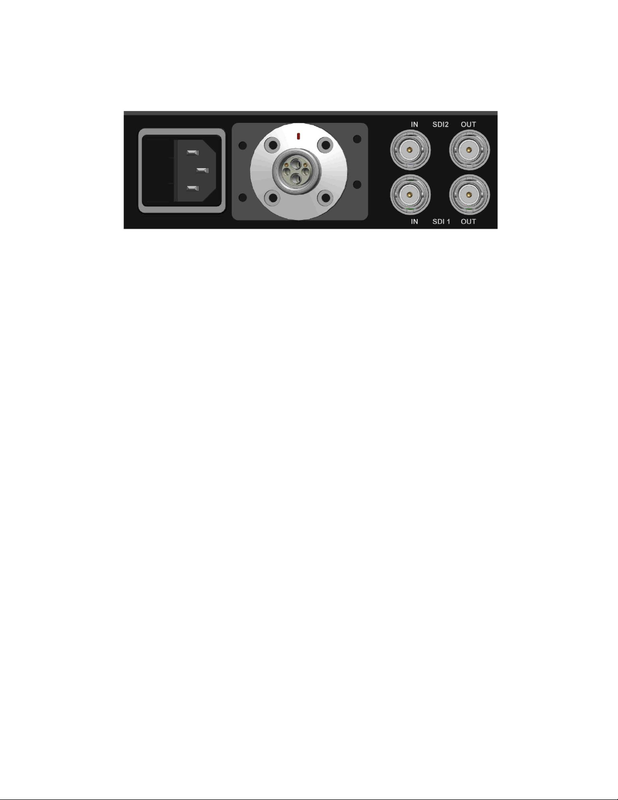
BASE UNIT
The SilverBack II base unit mounts directly in a standard 19-inch equipment rack and is 1 RU
(1.75-inch) in height.
The base unit includes a universal input power supply that ranges from 85 and 264 VAC, and
a detachable IEC320 power cord.
-20-
Page 24

Pin #
Function
Operator Headset (XLR
-5-F)
Audio 1 & 2 IN (XLR
-3-F)
Data 1 & 2 (LEMO ECG.
0
B.307.CLN)
R232
RS422
AUX Data / Audio (LEMO ECG.1B.316.CLN)
Table
1 -
Camera Unit Pin
-
Outs
APPENDIX A. Pin-Out specification
CAMERA UNIT PIN-OUTS
1 MIC L
2 MIC H
3 GND
4 Left Ear
5 Right Ear
1 GND
2 Audio In +
3 Audio In -
1 GND GND
2 RXD In RXD In 3 - TXD Out +
4 Tie to GND Leave Floating
5 - RXD In +
6 TXD Out TXD Out 7 - -
1 GPI 1 In
2 GPI 2 In
3 GPI 1 Out
4 GPO 2 Out
5 Headset MIC PTT
6 Tally Out
7 Return Audio 1 Out +
8 Return Audio 1 Out -
9 Return Audio 2 Out +
10 Return Audio 2 Out 11 LTC In
12 +12VDC Out
13 GND
14 GND
15 GND
16 LTC Out
-21-
Page 25

Pin #
Function
Tally (Riacon 31374105)
GPO (Riacon 31374105)
GPI (Riacon 31374105)
Data 1 & 2 (DB
-9-F)
R232
RS422
4-Wire Icom (Riacon 31374105)
2-Wire Com (XLR
-3-M)
BASE UNIT PIN-OUTS
1 GND
2 Tally In
3 GND
4 N/C
5 GND
1 GND
2 GPO 1
3 GPO 2
4 N/C
5 N/C
1 GND
2 GPI 1
3 GPI 2
4 N/C
5 N/C
1 - 2 TXD Out TXD Out 3 RXD In RXD In 4 Tie to GND Leave Floating
5 GND GND
6 - -
7 - TXD Out +
8 - RXD In +
9 +12VDC Out +12VDC Out
1 GND
2 Audio In +
3 Audio In 4 Audio Out +
5 Audio Out -
1 Return Audio 1 Out +
2 Return Audio 1 Out 3 Return Audio 2 Out +
-22-
Page 26

Pin #
Function
PGM IN (XLR
-3-F)
AUD 1,2 OUT (XLR
-3-M)
Table
2 -
Base Unit Pin
-
Outs
1 GND
2 Audio In +
3 Audio In -
1 GND
2 Audio In +
3 Audio In -
-23-
Page 27

Figure
24 -
SilverBack II Camera Side Block Diagram (Transmitter)
APPENDIX B. Block Diagrams
SILVERBACK II CAMERA SIDE BLOCK DIAGRAM (TRANSMITTER)
-24-
Page 28

Figure
25 -
SilverBack II Base Unit Block Diagram
SILVERBACK II BASE UNIT BLOCK DIAGRAM
-25-
Page 29

APPENDIX C. Technical Specifications
CAMERA UNIT
Bi-Directional Digital Video
Format Support: ................................................ SMPTE259M, 292M, 424M, 301M
Data Rate: ........................................................ 19Mbps to 3Gbps
Impedance: ....................................................... 75 Ohms
Signal Level: ..................................................... 800mVp-p, nominal
Inputs (Camera to Base): ................................. 1
Outputs (Base to Camera): ............................... 1
Analog Audio
Inputs (Camera to Base): .................................. 2
Type: ................................................................. MIC / Line, Balanced
Impedance: ........................................................ 20k, 2k, 600 ohms, selectable
Signal Level: ...................................................... +4 dBu nominal, +24dBu max.
Frequency Response: ....................................... ±0.5dB, 20Hz to 20kHz
Gain: .................................................................. 0 to 60 dB, selectable in 10 dB increments
MIC Phantom Power: ........................................ +48V, selectable on/off
PGM Audio / Talent IFB Output
Number of Channels: ......................................... 1
Type: ................................................................. Unbalanced
Connector: ........................................................ 3.5mm Stereo Jack
Controls: ........................................................... Volume
Intercom
Number of Channels: ........................................ 1
Compatibility: .................................................... Clear-Com, RTS
Headset Connector: .......................................... XLR-5 Female
MIC Type: ......................................................... Dynamic
MIC Impedance: ............................................... 200 Ohms, nominal
Controls: ........................................................... MIC Gain, Side-tone, PTT, Volume, PGM MIx
Data / Camera Control
Number of Channels: ........................................ 2, bi-directional
Format: .............................................................. RS232/RS422, TTL, selectable
Data Rate: ......................................................... Up to 1Mbps RS422, 115kbps RS232
Connector: ......................................................... LEMO 7-pin, 0B Series
Tally and GPIO
Number of Inputs: ............................................. 2
Logic “0” (Off): .................................................. TTL Low or short to GND
Logic “1” (On): .................................................. TTL High or +5V
Data Rate: ........................................................ Can support signals up to 1Mbps
Number of Outputs: .......................................... 2 + Tally
Output Type: ..................................................... Relay Contact, Form C, 30V 2A
-26-
Page 30

Electro-Optical
Operating Wavelengths: ................................... 1471-1531nm
Tx Laser Output Power: .................................... -2 to 0dBm, Class 1 Laser
Receiver Sensivity: ........................................... -18dBm
Fiber Compatibility: ........................................... Singlemode
Optical Connector Types: ................................. ST, OpticalCon DUO, SMPTE311
Mechanical / Environmental
Dimensions (LxWxH): ........................................ 7” x 7”x 1”
Weight: .............................................................. <3 lbs
Power Input: ...................................................... Gold Mount or V Mount Battery
Power Consumption: ......................................... 8 Watts
Environmental: ................................................... 0 to 50C, 0 to 95% RH, non-condensing
-27-
Page 31

BASE UNIT
Bi-Directional Digital Video
Format Support: ................................................ SMPTE259M, 292M, 424M, 301M
Data Rate: ........................................................ 19Mbps to 3Gbps
Impedance: ....................................................... 75 Ohms
Signal Level: ..................................................... 800mVp-p, nominal
Inputs (Camera to Base): ................................. 1
Outputs (Base to Camera): ............................... 1
Analog Audio
Outputs (Camera to Base): ................................ 2
Type: ................................................................. Balanced
Impedance: ........................................................ < 50 Ohms
Signal Level: ...................................................... +4 dBu nominal, +24dBu max.
Frequency Response: ....................................... ±0.5dB, 20Hz to 20kHz
PGM Audio / Talent IFB Output
Number of Channels: ........................................ 1
Type: ................................................................ Balanced
Impedance: ....................................................... 20k, 2k, 600 Ohms, selectable
Signal Level: ..................................................... +4 dBu nominal, +24 dBu max.
Frequency Response: ...................................... ±0.5dB, 20Hz to 20kHz
Intercom
Number of Channels: ........................................ 1
Compatibility: .................................................... Clear-Com, RTS
Type: ................................................................ 4-Wire, Balanced
Input Impedance: .............................................. 20k Ohms
Signal Level: ..................................................... +4 dBu nominal, +24 dBu max.
Frequency Response: ...................................... ±0.5dB, 20Hz to 20kHz
Output Impedance: ........................................... < 50 Ohms
Data / Camera Control
Number of Channels: ........................................ 2, bi-directional
Format: .............................................................. RS232/RS422, TTL, selectable
Data Rate: ......................................................... Up to 1Mbps RS422, 115kbps RS232
Connector: ......................................................... DB9-F
Tally and GPIO
Number of Inputs: .............................................. 2
Logic “0” (Off): ................................................... TTL Low or short to GND
Logic “1” (On): ................................................... TTL High or +5V
Data Rate: ......................................................... Can support signals up to 1Mbps
Number of Outputs: ........................................... 2 + Tally
Output Type: ...................................................... Relay Contact, Form C, 30V 2A
-28-
Page 32

Electro-Optical
Operating Wavelengths: ................................... 1471-1531nm
Tx Laser Output Power: .................................... -2 to 0dBm, Class 1 Laser
Receiver Sensivity: ........................................... -18dBm
Fiber Compatibility: ............................................ Singlemode
Optical Connector Types: .................................. ST, OpticalCon DUO, SMPTE311
Mechanical / Environmental
Dimensions (LxWxH): ........................................ 19” x 10.5”x 1.75”
Weight: .............................................................. 4 lbs
Power Input: ...................................................... IEC320, Universal Input, 90-264VAC
Power Consumption: ......................................... 20 Watts
Environmental: ................................................... 0 to 50C, 0 to 95% RH, non-condensing
Specifications are subject to change without notice.
-29-
 Loading...