

Page 1
Quick Start Guide
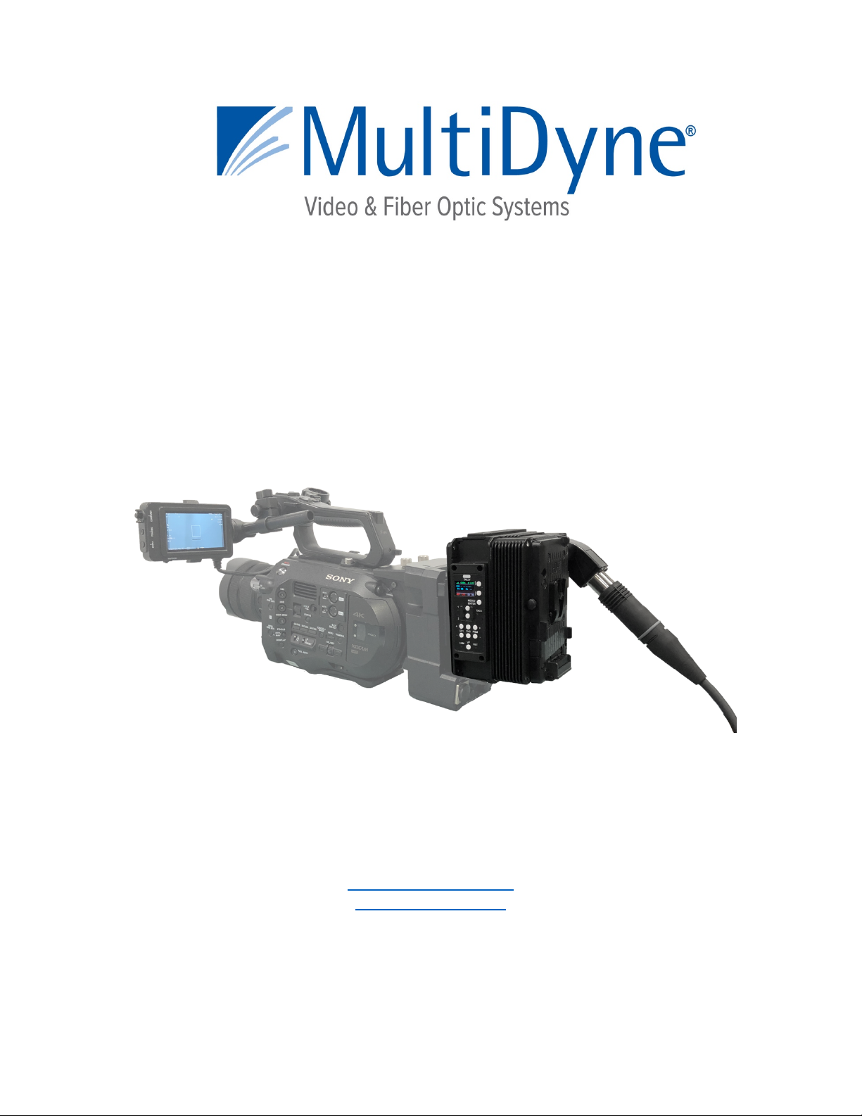
SilverBack V
CAMERA-BACK FIBER OPTIC TRANSCEIVER SYSTEM
(800)-488-8378 / (516)-671-7278 FAX (516)-671-3362
10 Newton Place
Hauppauge, NY 11788 USA
sales@multidyne.com
www.multidyne.com
Rev 2019-08-26
Page 2

Page 2
MULTIDYNE, the Multidyne logo, and SilverBack V are registered trademarks of
MULTIDYNE Electronics, Inc.
Copyright 2019 MULTIDYNE Electronics, Inc., Hauppauge, New York. Printed in the
United States of America. All Rights Reserved. Contents of this publication may not be
reproduced in any form without the written permission of MULTIDYNE Electronics, Inc.
This product was designed and manufactured in the
UNITED STATES of AMERICA
Page 3
Page 3
SilverBack V Camera-Mounted Tx Unit
The SilverBack-III family’s Camera side unit, also known as a “TX unit”, connects to a
camera’s rear battery plate (or it can be located separately, if required) and all the
signals from the camera are fed into this unit via a SMPTE hybrid cable (which includes
power) and communicates to a connector on the base station. This signal transport is
bi-directional, coming from the camera to the base station and vice versa.
Once mounted on the camera (via an Anton Bauer or “V”-mount battery bracket) the
SilverBack unit can have include an additional battery mounted on the outside of the
Camera I/O unit for extra protection against power failure or for working where readily
available AC power is not present.
The TX control panel’s simple interface lets the camera operator easily monitor system
link and signal status via an OLED display. Pushbuttons permit easy adjustment of
intercom levels and a menu system allows more detailed configuration of system
parameters.
Page 4

Page 4
Camera Video Connections:
Connect the camera’s primary SDI outputs to the 4K CAM inputs on the SBV Camera
Unit. Depending on the type of camera and video resolution being used, up to 4 BNC to
HDBNC cables may be needed. The 4K CAM inputs on the SBV Camera Unit are
highlighted in Blue.
The SBV Camera Unit’s 4K CAM inputs are capable of accepting Single Link, Dual Link,
and Quad Link video signals, supporting HD, 3G, and 4K resolutions up to 4Kp60.
Once the camera’s video resolution is known, and whether it is Single Link, Dual Link,
or Quad Link, the Gear-boxing Mode in the SBV Camera Unit’s Video Settings Menu
must be set accordingly.
Menu->Video Settings->Gearbox->Mode: Single, Dual 6G, Quad 3G
If your SBV Camera Unit is not 4K capable or does not contain a Gearbox, no menu
setting is necessary for the camera video. Connect the camera’s SDI output to the
CAM input on the SBV Camera Unit.
Reference Sync Connections:
Connect the SBV Camera Unit’s REF output to the camera’s Ref/Sync input using a
BNC to HDBNC cable. This REF output from the SBV Camera Unit is either analog
NTSC, PAL, or an HD Tri-Level signal that has been supplied to the Base Unit.
If the camera requires SDI Reference, connect one of the 3G SDI outputs of the SBV
Camera Unit to the Ref/Sync input on the camera using a BNC to HDBNC cable. This
output will be the same signal that is connected to the corresponding SDI Input on the
Base Unit.
Timecode Connections and Operation:
Connect the SBV Camera Unit’s TC connector to the camera’s TC connector using a
BNC to HDBNC cable. This TC connector on the SBV Camera Unit can either be an
output or an input, supplying Timecode to the camera from the Base Unit or sending
Timecode to the Base Unit from the camera.
The direction of this Timecode connector on the SBV Camera Unit is set in the SBV
Camera Unit Menus.
Menu->System Settings->Timecode->Direction
Page 5

Page 5
Secondary SDI Connections
The SBV Camera Unit may be equipped with 1 or more secondary SDI paths,
depending on the model number ordered. These may be all camera returns, all sends,
or a combination of both. The secondary SDI paths are 3G capable, they do not
support 6G or 12G SDI.
The secondary SDI connectors on the SBV Camera Unit are highlighted in Green and
the label indicates their direction. Connect your secondary SDI signals using BNC to
HDBNC cables.
Built-in Viewfinder Switch
On SBV Camera Units configured with either Dual SDI returns or a single SDI send and
single SDI return, a built-in Viewfinder Switch feature is available to switch an externally
connected Viewfinder between the camera’s monitor output and a return video feed.
This feature may be disabled in the SBV Camera Unit Menus if this functionality is not
needed.
Menu->Video Settings->Viewfinder->Enable: On. Off
Menu->Video Settings->Viewfinder->Slot Num: 1-4 (depends on the number and type of SDI cards
installed)
Connect the camera’s Monitor output or secondary SDI output to the viewfinder CAM
connector on the SBV Camera Unit using a BNC to HDBNC cable. Connect the
viewfinder OUT connector on the SBV Camera Unit to the SDI input of the external
Viewfinder monitor using a BNC to HDBNC cable.
Note that the directions of the Secondary SDI BNC connectors on the SBV Camera Unit
will be different when the Viewfinder Switch is enabled versus when it is disabled.
When the Viewfinder switch is enabled, the Viewfinder button on the SBV Camera
Unit’s control panel is used to select the video source that is output from the Viewfinder
HDBNC Connector. Pressing this button will change between the video signal
connected to the VF input (typically the Camera’s video output) and the Return 1 video
being sent by the base station. LED’s on the control panel indicate which source is
currently switched to the Viewfinder output.
An external switch connected to the DB-15 GPIO connector on the SBV Camera Unit
may also be used to control the Viewfinder output, please refer to the pinout guide for
pinout information. The Viewfinder select pin on the GPIO connector is typically used
with a momentary type pushbutton switch. When this pin is connected to Ground, the
Viewfinder Output HDBNC will output Return 1 video. When this pin is left open or
unconnected, the Viewfinder Output HDBNC will output the video signal connected to
the VF input (typically the Camera’s video output).
Page 6

Page 6
Ethernet Connection:
The SBV Camera Unit may be equipped with an Ethernet port, depending on the model
number ordered. The Ethernet port is 10/100/1000 Mbps and may be connected to the
camera and/or other devices local to the camera. Using Cat5e cable is recommended.
Intercom Headset Connection and Operation:
The SBV Camera Unit may be equipped with an Intercom Headset port, depending on
the model number ordered. This port uses a 5-pin miniXLR connector to support both
single and dual muff intercom headsets. An adapter cable from miniXLR to standard
size XLR is available.
Headset MIC Gain and Sidetone settings are adjusted in the SBV Camera Unit Menus:
Menu->Audio Settings->Intercom>MIC Gain
Menu->Audio Settings->Intercom>Sidetone
Volume controls are provided on the SBV Camera Unit control panel for adjusting the
audio levels of Intercom Ch1, Intercom Ch2, and Program audio heard in the headset.
The volume controls allow for a mix of both intercom channels and program audio all to
be listened to in the headset simultaneously. The LED above each channel’s set of
volume control buttons will illuminate whenever audio is present on that channel. When
adjusting the volume, these LED’s will rapidly blink 3 times whenever the min or max
volume setting has been reached.
Two Push-To-Talk (PTT) switches are provided on the SBV Camera Unit control panel,
1 for each intercom channel, for activating Talkback. Each PTT switch provides
Momentary/Latching operation of the headset microphone to allow the operator to talk
on a particular intercom channel, or on both channels simultaneously.
For Momentary Mode, press and hold the PTT switch down for the intercom channel
you wish to speak on and then speak into the microphone. The TALK and the selected
intercom channel LED’s will blink and the mic will remain open while the PTT switch is
held. Release the PTT switch when finished talking. The mic will close and the TALK
and channel LED’s will turn off.
Latching Mode can be used for longer-term, hands-free operation. To talk on channel
1, quickly press and release the Ch 1 PTT switch. The mic will latch open and the TALK
and CH1 LED’s will blink continuously. When finished talking, quickly press and release
the Ch1 PTT switch again. The mic will then close and the TALK and CH1 LED’s will
turn off.
Page 7

Page 7
To talk on channel 2, quickly press and release the Ch 2 PTT switch. The mic will latch
open and the TALK and CH2 LED’s will blink continuously. When finished talking,
quickly press and release the Ch2 PTT switch again. The mic will then close and the
TALK and CH2 LED’s will turn off.
To talk on both channels 1 and 2 simultaneously, first quickly press and release the Ch1
PTT switch to activate latching mode. The mic will latch open and the TALK and CH1
LED’s will blink continuously. Next, quickly press and release the Ch2 PTT switch to
activate its latching mode. The mic will stay open and now the TALK, CH1 and CH2
LED’s will all blink continuously. When finished talking, quickly press and release the
Ch1 PTT switch to disengage CH1 (the CH1 LED will turn off) then quickly press and
release the PTT switch to disengage CH2 (the CH2 LED will turn off). The mic will close
and the TALK, CH1 and CH2 LED’s will all turn off.
An external switch connected to the DB-15 GPIO connector on the SBV Camera Unit
may also be used to control Intercom Talkback operation, please refer to the pinout
guide for pinout information. Two mic trigger GPI pins are provided, one for CH1 and
one for CH2. A single SPDT momentary type switch or 2 SPST switches may be used.
Audio Connections and Operation:
The SBV Camera Unit may be equipped with Dual Channel MIC/Line Inputs, 4 Ch
Line/2AES Inputs and Outputs, or both, depending on the model number ordered.
The MIC/Line Inputs use 3-pin miniXLR connectors and support analog Line-Level
audio or MIC Level audio with 48V Phantom capability and adjustable Gain up to 60dB
when in MIC mode. MIC/Line settings are adjusted in the SBV Camera Unit Menus.
Menu->Audio Settings->Input->MIC/Line Setting->Mic/Line1->Mode: Line, MIC
Menu->Audio Settings->Input->MIC/Line Setting->Mic/Line1->Gain: 0 to 65 dB
Menu->Audio Settings->Input->MIC/Line Setting->Mic/Line1->Phantom: 48V, Off
Menu->Audio Settings->Input->MIC/Line Setting->Mic/Line2->Mode: Line, MIC
Menu->Audio Settings->Input->MIC/Line Setting->Mic/Line2->Gain: 0 to 65 dB
Menu->Audio Settings->Input->MIC/Line Setting->Mic/Line2->Phantom: 48V, Off
Note that Gain and Phantom Settings may be changed when in MIC Mode. When in
Line Mode, Phantom power is turned off and Gain is set to 0dB (unity gain).
The 4 Channel Line Level I/O uses a 26-pin MDR connector. From an input
perspective, this connector supports 4 Line-Level balanced mono input channels or 2
balanced AES inputs. From an output perspective, this connector supports 4 Line-Level
balanced mono output channels or 2 balanced AES outputs.
Selection between analog and AES is on a stereo-pair basis using the SBV Camera
Unit Menus.
Page 8

Page 8
Menu->Audio Settings->Input->In 1/2 Source: DB-Line, DB-AES, MIC/Line
Menu->Audio Settings->Input->In 3/4 Source: DB-Line, DB-AES
Menu->Audio Settings->Output->Out 1/2 Type: Line, AES
Menu->Audio Settings->Output->Out 3/4 Type: Line, AES
Breakout cables are available for miniXLR to XLR and MDR to XLR.
Serial Data Connections and Operation:
The SBV Camera Unit may be equipped with two Serial Data Ports for controlling
cameras with serial control, or other external devices with serial control. The two data
ports are combined in a single HD-15 connector on the SBV Camera Unit.
The Serial Data Ports support RS232, RS422, LANC, and TTL level data. Pre-made
cable kits for specific camera manufacturers, e.g. Sony and Panasonic, are available. It
is necessary to configure specific data type for each port in SBV Camera Unit as the
internal settings are different for LANC vs RS232/422/TTL.
Menu->Data Settings->Data 1: RS232/422, LANC
Menu->Data Settings->Data 2: RS232/422, LANC
GPIO Connections:
The SBV Camera Unit may be equipped with a GPIO Port for interfacing with other
devices as well as controlling certain functions within the SBV Camera Unit using GPI’s.
All the GPOI function pins are combined in a single HD-15 connector on the SBV
Camera Unit.
The GPI functions are as follows:
• Generic GPI Input passed down to the Base Unit
• Generic GPO Output passed up from the Base Unit (relay contact closure)
• Red Tally Output (relay contact closure)
• Green Tally Output (relay contact closure)
• Two Headset MIC PTT GPI Inputs (one for each intercom channel)
• External Viewfinder Source Select GPI Input
• Generic GPI Input for controlling a SBV Camera Unit Function (future use)
Page 9

Page 9
SilverBack V Base Rx Unit
The SilverBack V family’s Base side unit, also known as a “RX unit”, connects to up to 2
camera units and all the signals from each camera chain are fed into this unit via
SMPTE hybrid cables (which can include power). This signal transport is bi-directional,
coming from the camera to the base station and vice versa.
Internally, the Base Station contains redundant 12V power supplies for powering the
Base Unit electronics as well as separate individual power supplies for powering each
camera chain.
The Base Station front panel’s simple interface lets the operator easily monitor system
link and signal status via a TFT display. Dedicated status LED’s permit easy monitoring
of key signals levels and a menu system on the TFT display allows more detailed status
and configuration of system parameters.
Connecting the Base Unit
The SBV Base Unit is to be mounted in a standard 19” equipment rack. AC connector 1
is used to power the Base Unit and Camera Chain 1. AC connector 2 is used to power
Camera Chain 2 and provide redundant power to the Base Unit.
Page 10

Page 10
Camera Video Connections:
Connect the 4K CAM outputs of the SBV Base Unit to the desired facility destination.
Depending on the type of camera and video resolution being used, up to 4 HDBNC
cables may be needed. The 4K CAM outputs on the SBV Base Unit are highlighted in
Blue.
The SBV Base Unit’s 4K CAM outputs are capable of outputting Single Link, Dual Link,
and Quad Link video signals, supporting HD, 3G, and 4K resolutions up to 4Kp60.
Once the camera’s video resolution is known, and whether it is Single Link, Dual Link,
or Quad Link, the Gear-boxing Mode in the SBV Base Unit’s Video Settings Menu must
be set accordingly.
Base Menu->Settings->Video->Cam1 Output: Single Link, Dual Link, Quad Link
Base Menu->Settings->Video->Cam2 Output: Single Link, Dual Link, Quad Link
If your SBV system is not 4K capable or does not contain a Gearbox, no menu setting is
necessary for the camera video. Connect the camera SDI output on the SBV Base Unit
to the desired facility destination.
Reference Sync Connections:
Each camera chain in the SBV Base unit has a dedicated Reference Sync Input.
Connect the desired sync reference to these ports. This REF input can accept either
analog NTSC, PAL, or an HD Tri-Level signal. The 2 HDBNC connectors for each
camera chain’s reference are internally connected together as a loop-thru. It is
recommended to put a 75 ohm termination on the loop-thru connector.
The SBV Base unit also has the ability to route either of the Reference Sync inputs to
either or both camera units. This way, only a single reference signal is needed per
frame. The Reference Sync routing is configured in the SBV Base Menus.
Base Menu->Settings->Reference>Cam1 Ref: In1, In2
Base Menu->Settings->Reference>Cam2 Ref: In1, In2
If the camera requires SDI Reference, use one of the 3G SDI return inputs on each of
the camera chains of the SBV Base Unit to provide reference to the cameras.
Timecode Connections:
Each camera chain in the SBV Base Unit has dedicated Timecode Inputs and Outputs.
Connect Timecode inputs/outputs to these ports as necessary. Note that in order for a
Page 11

Page 11
camera chain in the Base to output the camera’s timecode output, the direction of the
Timecode connector on the SBV Camera Unit must be set as an input.
The SBV Base Unit also has the ability to route either of the Timecode inputs to either
or both camera units. This way, only a single timecode reference signal is needed per
frame. The Timecode routing is configured in the SBV Base Menus.
Base Menu->Settings->Reference>Cam1 LTC: In1, In2
Base Menu->Settings->Reference>Cam2 LTC: In1, In2
Secondary SDI Connections
Each camera chain in the SBV Base Unit may be equipped with 1 or more secondary
SDI paths, depending on the model number ordered. These may be all camera returns,
all sends, or a combination of both. The secondary SDI paths are 3G capable, they do
not support 6G or 12G SDI.
The secondary SDI connectors on the SBV Base Unit are highlighted in Green and the
label indicates their direction. Connect your secondary SDI signals using HDBNC
cables.
Camera Ethernet Connection:
Each camera chain in the SBV Base Unit may be equipped with a 2-port Ethernet card,
depending on the model number ordered, providing an Ethernet path for the camera.
The Ethernet ports are 10/100/1000 Mbps and both RJ45 ports on the card are
connected to an internal Ethernet switch.
The 1st port is typically connected to the facility’s network switch. The 2nd port may be
connected to the 2nd camera chain camera and/or other devices if desired. Using
Cat5e cable is recommended.
Intercom, Tally, and GPIO Connections:
Each camera chain in the SBV Base Unit is equipped with an Intercom Interface,
supporting both 2-Wire Party-Line and 4-Wire Intercom systems. The Intercom
Interfaces use a DB25 connection and follows the pinout used by Sony and Panasonic
SMPTE camera CCU’s. Intercom, Tally, and GPIO signals are all combined into these
connectors.
2-Wire or 4-Wire Intercom Type selection is made through the SBV Base Unit Menus:
Page 12

Page 12
Base Menu->Settings->Intercom>Intercom Type: 2-Wire, 4-Wire
When in 2-Wire mode, each camera chain’s internal 2-Wire interface needs to be Nulled
after initial installation.
Base Menu->Settings->Intercom>2-Wire Autonull->: Cam1 Ch1
Base Menu->Settings->Intercom>2-Wire Autonull->: Cam1 Ch2
Base Menu->Settings->Intercom>2-Wire Autonull->: Cam2 Ch1
Base Menu->Settings->Intercom>2-Wire Autonull->: Cam2 Ch2
GPI Inputs are simple pull to Ground to activate and the GPO output provides a relay
contact closure to Ground when activated. The Tally/GPIO signals in the Intercom
Interface Connector are shown below.
Red Tally Input (pull to GND to activate)
Green Tally Input (pull to GND to activate)
Generic GPI Input passed up to the Camera Unit (pull to GND to activate)
Generic GPO Output passed down from the Camera Unit (relay contact closure)
Audio Connections and Operation:
Each camera chain in the SBV Base Unit is equipped with a Bi-Directional 4 Channel
(mono) audio interface. Inputs and outputs may either be analog Line-Level or AES. All
channels are balanced connections.
Each interface uses a DB25 connector and follows the Tascam channel numbering
convention. The first four channels are used for the audio inputs and the last 4 channels
are used for the audio outputs.
When using AES, only the odd numbered channels are used as AES is a 2-channel
interface. Selection between analog and AES is made on a stereo-pair basis using the
SBV Base Unit Menus.
Base Menu->Settings->Audio Inputs->Cam1 Input 1/2: Analog, AES
Base Menu->Settings->Audio Inputs->Cam1 Input 3/4: Analog, AES
Base Menu->Settings->Audio Inputs->Cam2 Input 1/2: Analog, AES
Base Menu->Settings->Audio Inputs->Cam2 Input 3/4: Analog, AES
Base Menu->Settings->Audio Outputs->Cam1 Output 1/2: Analog, AES
Base Menu->Settings->Audio Outputs->Cam1 Output 3/4: Analog, AES
Base Menu->Settings->Audio Outputs->Cam2 Output 1/2: Analog, AES
Base Menu->Settings->Audio Outputs->Cam2 Output 3/4: Analog, AES
Page 13

Page 13
Serial Data Connections:
Each camera chain in the SBV Base Unit is equipped with two Serial Data Ports for
controlling cameras with serial control, or other external devices with serial control.
Each data port uses a dedicated DB-9 connector on the rear of the SBV Base Unit.
The Serial Data Ports support RS232, RS422, LANC, and TTL level data. Pre-made
cable kits for specific camera manufacturers, e.g. Sony and Panasonic, are available.
It is necessary to configure specific data type for each port in SBV Base Unit as the
internal settings are different for LANC vs RS232/422/TTL.
Base Menu->Settings->Data->Cam1 Data 1: RS232/422, LANC
Base Menu->Settings->Data->Cam1 Data 2: RS232/422, LANC
Base Menu->Settings->Data->Cam2 Data 1: RS232/422, LANC
Base Menu->Settings->Data->Cam2 Data 2: RS232/422, LANC
Frame Controller
You can monitor the status and control settings in your SilverBack V Base frame via a
Web page dashboard that is embedded within the frame. The steps for connecting to
your facility’s Ethernet network will depend on the network requirements of your facility.
Contact your IT Department before connecting to your facility network to ensure that
there will not be any conflicts.
Network Settings:
The method for setting the IP address of the SilverBack V Base Unit is determined
using the 4-position DIP switch on the rear of the chassis. The four possible settings for
IP address configuration are outlined below:
• Preset IP address configuration — the network controller card in the frame can be forced to use
one of two specific predefined IP address settings. This can be used to establish initial
communications, configure the frame for future deployment on another network, or to override a
custom user configuration.
• User-defined IP address configuration — the network controller card in the frame can be
configured to use a user-defined static IP address from the device’s embedded Web page. Reconfiguration can only be done once network communications have been established.
• Automatic configuration using DHCP — the network controller card in the frame is configured to
automatically obtain network settings from a Dynamic Host Configuration Protocol (DHCP)
server. This method would be recommended for advanced users only as there is no way to
display the DHCP assigned address on the frame itself.
The physical DIP switching settings are shown below. Only one switch is allowed to be
in the ON position.
Page 14

Page 14
DIP Switch #
Description
1
DHCP. Network settings assigned by a DHCP server
2
User IP Address. IP Address is set by the user through embedded webpage.
Factory default is 192.168.1.249
3
Fixed IP Address #1. 192.168.2.2
4
Fixed IP Address #2. 10.1.1.2
Note — The IP Addresses of the SilverBack V Base Unit and your computer must be on
the same Subnet. For example, if the SilverBack V Base Unit has an IP Address of
192.168.2.2, then your computer should be configured for an IP address of 192.168.2.X
where X is a number other than 2.
To use one of the fixed preset IP addresses:
1. Set the DIP Switch to specify the desired preset IP address as outlined in the IP address DIP
switch table.
2. Ensure the network settings of your computer are compatible with those chosen for the
SilverBack V Base Unit frame. Both your computer and the SilverBack V Base Unit must be on
the same subnet. Contact your IT Department if you need help determining or configuring the
network settings of your computer.
3. To prevent any possible IP address conflicts, initially isolate the SilverBack V Base Unit frame
and your computer from the rest of your network.
• If you are using a hub or switch, unplug all devices except the SilverBack V Base Unit
frame and your computer
or
• Connect the SilverBack V Base Unit frame directly to your computer with an Ethernet
cable.
4. Launch a web browser on your computer.
5. Power up the SilverBack V Base Unit frame.
6. In the address bar of the web browser, enter the preset IP address selected on the DIP switch.
7. Wait approximately 30 seconds while the frame establishes network communications.
8. Verify that the SilverBack V Base Unit Dashboard webpage displays in the web browser.
9. Should the webpage fail to display after a minute or two:
• Click the refresh/reload button in your browser.
• Verify the Ethernet cables are properly connected.
• Check the link/activity LEDs found on the Ethernet RJ-45 connectors.
• Verify that you have properly performed each step of this procedure.
• Contact MultiDyne Technical Support if you cannot establish a connection
Page 15

Page 15
To use a Custom User IP Address via webpage Dashboard
Once network communications have been established with a SilverBack V Base Unit, a
custom static IP address can be configured through the Frame Ethernet Settings box in
the webpage Dashboard.
To configure the User IP address using the webpage Dashboard:
1. Establish Ethernet communications with the SilverBack V Base Unit using one of the preset
IP addresses, DHCP, or previously configured User IP address and load the device's
Dashboard webpage in a web browser by entering the IP address in the browser's address
bar.
2. In the Frame Ethernet Settings Box, enter the desired User IP address in the User IP boxes.
3. Ensure the new network settings chosen for the SilverBack V Base Unit are compatible with
the network the SilverBack V Base Unit is to be employed in. The computer used for
monitoring the SilverBack V Base Unit must be on the same subnet. Contact your IT
Department if necessary.
4. Verify the IP address entered is correct and then click the "Save IP" Button. This IP address
will be stored in non-volatile memory on the frame controller card.
5. The new IP address will not take effect until the IP Address DIP switch is changed to the User
IP address position. If the DIP switch is already in the User IP position, a toggle of the User
IP position switch from off to back on again may be required for the new address to take
effect.
6. Enter the new IP address in the address bar of a web browser and hit enter to verify the new
IP address.
Page 16

Page 16
To use DHCP to automatically assign network settings
Network settings for the SilverBack V Base Unit may be automatically configured via a
DHCP server on the facility network. This method would be recommended for
advanced users only as there is no way to display the DHCP assigned address on the
frame itself.
To configure the network settings via DHCP:
1. Connect the SilverBack V Base Unit to your network using an Ethernet cable.
2. Power up the SilverBack V Base Unit.
3. Set the DIP Switch position 1 to ON to specify DHCP configured settings.
Physically Identifying a SilverBack V Base Unit in a facility
On the rear of the chassis, there is an ID LED which can be used to help identify the
location of a particular SilverBack V Base Unit. The Frame ID LED button in the
Ethernet Settings Box of the webpage allows you to turn this LED ON or OFF. When
turned ON, the LED on the chassis will blink.
Page 17

Base Unit Intercom/GPIO Connector Pinout
DB25-F
Number
Description
Number
Description
1
2-Wire Intercom Pin2 / 4-Wire
Intercom Ch1 Output+
14
2-Wire Intercom Pin3 / 4-Wire
Intercom Ch2 Output+
2
4-Wire Intercom Ch1 Output-
15
4-Wire Intercom Ch2 Output-
3
GND
16
GND 4 4-Wire Intercom Ch1 Input+
17
4-Wire Intercom Ch2 Input+
5
4-Wire Intercom Ch1 Input-
18
4-Wire Intercom Ch2 Input-
6
PGM Audio Ch1 Input+
19
PGM Audio Ch2 Input+
7
PGM Audio Ch1 Input-
20
PGM Audio Ch2 Input-
8
GND
21
GND
9
GND
22
N/C
10
GPI Input 1
23
GPO Output 1
11
Red Tally GPI In
24
Green Tally GPI In
12
GND
25
GND
13
GND
Follows Sony/Panasonic CCU Convention
Base Unit Audio Connector Pinout
DB25-F
Number
Description
Number
Description
1
Ch4 Analog Audio Output+
14
Ch4 Analog Audio Output-
2
GND
15
Ch3 Analog Audio Output+
or AES2 Output+
3
Ch3 Analog Audio Outputor AES2 Output-
16
GND
4
Ch2 Analog Audio Output+
17
Ch2 Analog Audio Output-
5
GND
18
Ch1 Analog Audio Output+
or AES1 Output+
6
Ch1 Analog Audio Outputor AES1 Output-
19
GND
7
Ch4 Analog Audio Input+
20
Ch4 Analog Audio Input-
8
GND
21
Ch3 Analog Audio Input+
or AES2 Input+
9
Ch3 Analog Audio Inputor AES2 Input-
22
GND
10
Ch2 Analog Audio Input+
23
Ch2 Analog Audio Input-
11
GND
24
Ch1 Analog Audio Input+
or AES1 Input+
12
Ch1 Analog Audio Inputor AES1 Input-
25
GND
13
N/C
Follows Tascam Convention
SBV Connector Pinouts – Base Unit
Page 17
Page 18

Base Unit Data Connector Pinout
DB-9F
Number
RS232 Pinout
RS422 Pinout
1
N/C
TTL Bias
2
TXD Out
TXD Out -
3
RXD In
RXD In -
4
Tie to GND
N/C
5
GND
GND 6 N/C
N/C 7 N/C
TXD Out +
8
N/C
RXD In +
9
+12V Out
+12V Out
Page 18
Page 19

Camera Unit Intercom Headset Audio Connector Pinout
miniXLR-5F
Number
Description
1
GND
2
MIC Input+
3
GND
4
Audio L Output
5
Audio R Output
Camera Unit MIC/Line Audio Input Connector Pinout
miniXLR-3F
Number
Description
1
GND
2
Input+
3
Input-
Camera Unit Audio Connector Pinout
MDR26-F
Number
Description
Number
Description
1
GND
14
GND
2
Ch1 Analog Audio Inputor AES1 Input-
15
Ch1 Analog Audio Output+
or AES1 Output -
3
Ch1 Analog Audio Input+
or AES1 Input+
16
Ch1 Analog Audio Outputor AES1 Output +
4
GND
17
GND 5 Ch2 Analog Audio Input+
18
Ch2 Analog Audio Output +
6
Ch2 Analog Audio Input-
19
Ch2 Analog Audio Output -
7
GND
20
GND
8
Ch3 Analog Audio Input+
or AES2 Input+
21
Ch3 Analog Audio Output +
or AES2 Output +
9
Ch3 Analog Audio Inputor AES2 Input-
22
Ch3 Analog Audio Output or AES2 Output -
10
GND
23
GND
11
Ch4 Analog Audio Input+
24
Ch4 Analog Audio Output +
12
Ch4 Analog Audio Input-
25
Ch4 Analog Audio Output -
13
GND
26
GND
Follows Multidyne VB Audio Series Convention
SBV Connector Pinouts – Camera Unit
Page 19
Page 20

Page 20
Camera Unit Serial Data Connector Pinout
HDB15-F
Number
RS422 Pinout
RS232 Pinout
Number
RS422 Pinout
RS232 Pinout
1
Data1 RXD In-
Data1 RXD
9
Data2 TTL Bias
N/C
2
Data1 RXD In+
N/C
10
GND
GND
3
N/C
Tie to GND
11
Data1 TXD Out-
Data1 TXD
4
Data2 RXD In-
Data2 RXD
12
Data1 TXD Out+
N/C
5
Data2 TXD Out+
N/C
13
N/C
N/C
6
Data1 TTL Bias
N/C
14
Data2 TXD Out-
Data1 TXD
7
GND
GND
15
Data2 RXD In+
GND
8
N/C
Tie to GND
Camera Unit GPIO Connector Pinout
HDB15-F
Number
Description
Number
Description
1
Red Tally Output
9
GND 2 Green Tally Output
10
GND
3
GPO 1 Output
11
Ch1 ICOM MIC Talk Trigger GPI Input
4
GPI 1 Input
12
Ch2 ICOM MIC Talk Trigger GPI Input
5
N/C
13
VF Input Select GPI Input
6
GND
14
REC Trigger GPI Input
7
GND
15
+12VDC Output, 1A Max
8
GND
 Loading...