

Page 1

INSTRUCTION MANUAL
HD-3500 Series
SERIAL DIGITAL VIDEO, DATA, AND AUDIO,
FIBER OPTIC TRANSPORT & DISTRIBUTION
SYSTEM FOR HDTV & SDTV
MultiDyne
Video at Light Speed
191 FOREST AVENUE
LOCUST VALLEY, NY 11560-2132 USA
(800)-488-8378 / (516)-671-7278 FAX (516)-671-3362
sales@multidyne.com
www.multidyne.com
REV F, April 1, 2015
Page 2

MULTIDYNE and HD-3500 are registered trademarks of MULTIDYNE Electronics, Inc.
Copyright 2009 MULTIDYNE Electronics, Inc., Locust Valley, New York. Printed in the United
States of America. All Rights Reserved. Contents of this publication may not be reproduced
in any form without the written permission of MULTIDYNE Electronics, Inc.
This product was designed and manufactured in the
UNITED STATES of AMERICA
REV F, April 1, 2015
Page 3

TABLE OF CONTENTS
INTRODUCTION ..................................................................................................................... 1
FEATURES AND OPERATION ............................................................................................... 1
TRANSMITTER, HD-3500-FTX ........................................................................................... 2
RECEIVER, HD-3500-FRX .................................................................................................. 5
POWER REQUIREMENTS .................................................................................................. 7
INSTALLATION ................................................................................................................... 7
APPENDIX A. PIN-OUT SPECIFICATION .............................................................................. 8
APPENDIX B. BLOCK DIAGRAMS ......................................................................................... 8
APPENDIX C. TECHNICAL SPECIFICATIONS .................................................................... 11
APPENDIX D. OPTIONAL DIVING BOARD .......................................................................... 13
REV F, April 1, 2015
Page 4

Instruction Manual, HD-3500 Series
INTRODUCTION 1
INTRODUCTION
The HD3500 Series of stand-alone SMPTE 3G video High Definition Serial Digital
Interface (HD-SDI) with audio and data transport systems extends the range limits of
electrical interfaces, and combines audio and data along with the HD-SDI signal in a single
optical fiber link. The system will transport digital signals from 5 Mbps up to 2.970 Gbps,
analog audio, AES digital audio, serial data, intercom, tally, and General Purpose I/O (GPIO)
signals.
Applications include transmission links for high definition or digital television, studio to
transmitter; studio-to-studio, robotic studio cameras, studio to CATV head-end and backhaul
feeds from special events. The transmitter and receiver units are available in portable or
stand-alone and modular configurations ideal for both field and studio applications.
FEATURES and OPERATION
The HD3500 supports all popular standards for digital video transport such as SMPTE
259M-C, SMPTE 292M, and SMPTE 424, working at 270 Mbps, 1.495 Gbps, and 2.970
Gbps respectively. In addition, the HD-SDI interface also will transport signals compatible
with DVB/ASI, and SMPTE 297M interfaces at the defined rates. The units include a digital
reclocked DA and repeater for the SMPTE SDI standards mentioned above. For other
standards and rates, the signal is automatically or manually passed thru without reclocking.
For the SDI/HD-SDI input, the units include automatic cable equalization based on the data
rate detected.
Separate from the SMPTE video transport, the HD-3500 also transports 4 analog
audio channels with maximum configurable levels of 4dBu, 10dBu, 16dBu, or 28 dBu; 2
digital AES pairs up to 96Khz that cross convert with the 4 analog channels; and a
bidirectional stereo channel for intercom applications with maximum level of 4dBu. The
system also supports 4 GPIO bidirectional channels with open collector inputs capability and
relay contact for the outputs; 1 bidirectional tally IO with open collector input and contact
relay output; and 3 bidirectional serial data channels compatible with RS232 or RS422
transport up to 3Mbps.
To accomplish SMPTE video with bidirectional audio and data transport, 3
wavelengths are multiplexed over a single fiber using a CWDM module, a 1310nm optic used
for SMPTE video, and 1490nm and 1550nm optics are used for the bidirectional audio and
data transport. The SMPTE video input and output use standard BNC connectors while the
audio and data use a DB44 connector with either a special breakout cable assembly or a
diving board. See appendix A for pin-out information.
REV F, April 1, 2015
Page 5
Instruction Manual, HD-3500 Series
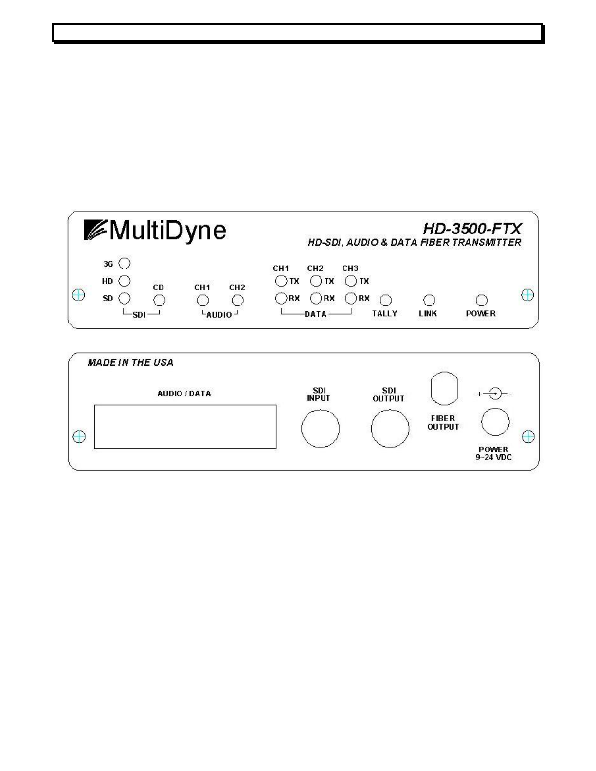
Figure
1
. Front and Back of HD
-
3500
-
FTX
FEATURES and OPERATION 2
TRANSMITTER, HD-3500-FTX
The transmitter module front and back is shown in figure 1. In the back and from left to
right it includes a DB44 connector for all audio and data IO; two serial digital video SMPTE
75 Ohm input BNC connectors, one for input and one for reclocked SDI / HD-SDI output loop;
a single fiber output ST or SC connector; and a DC Jack power connector. In the front of the
module we see 3 SMPTE SDI lock LEDs for 270 Mbps, 1.485 Gbps and 2.970 Gbps rates;
SMPTE SDI CD (Carrier Detect) LED; 2 audio status LED that indicate channel 1 and 2 level,
peak, or AES presence; 6 data activity LEDs to indicate TX and RX activity in the 3 data
channels; a tally on indicator LED; a link status LED; and a power LED.
SMPTE video transport
5Mbps to 3Gbps. The SMPTE video signal is connected to the 75 ohms BNC input connector
in the back. Signals with rates from 19 Mbps to 3Gbps are then equalized. Equalization is
used to help open the digital video eye pattern that may have been closed or deteriorated
due to long coaxial cable runs. After equalization, the signal is reclocked and sent to the fiber
transport and to a 75-ohm loop output, which is the second BNC connector in the back. The
front rate LEDs indicate that a valid SMPTE rate is locked by the re-clocker PLL. The Carrier
Detect (CD) LED indicates that a signal has been applied to the input. Carrier Detect is
sensitive to digital carriers from 19Mbps to 3Gbps.
Non-SMPTE transport via the SMPTE interface
indicated earlier; however, other signals may need special settings. The SMPTE video input
has a feature that automatically mutes signals as noise or other signals under 19Mbps. If you
need to transport these signals, the auto mute feature can be disabled changing the jumper
The HD-3500-TX receives SMPTE video or other properly encoded data signals from
The HD3500 will operate normally by default with SMPTE video signals at the rates
REV F, April 1, 2015
Page 6

Instruction Manual, HD-3500 Series
on=RS232
on=RS232
on=RS232
on=48KHz
off = 110 Ohms AES3 Bal
. Input
off = 110 Ohms AES3
Bal. Input
Table
1
. Settings for AES Audio and Data Types
Figure 2
. Default settings and placement for J10 and J5
FEATURES and OPERATION 3
J10 from the 1-2 to the 2-3 position, see figure 2 with default setting. Non-SMPTE standard
signals should automatically put the reclocker into bypass mode; however, in some
instances, if the signal has components close to the SMPTE frequencies, there may be
glitches on the operation. To void this, there is another jumper, J5 that when inserted will
force the reclocker into bypass mode. The default setting for J5 is open as shown below.
Audio Transport
This unit can transport two balanced stereo pairs (4 monos), or two AES channels of
high quality audio. The unit automatically detects if AES audio is present in each channel to
be selected, otherwise the corresponding analog stereo pair is selected. The AES channels
can be set for 110 ohms balanced input mode or 75 Ohms singled ended input (see table 1).
The analog stereo pairs can be set for different full scale (FS) levels using a dip switch, 600
ohms input mode, or +6dB compensation (see tables 2 and 3). The audio LEDs indicate
three possible statuses: constant blinking green indicates AES signal is present, green
indicates analog level is present with a level from -8dBFS to -1dBFS, and red indicates
clipping. Even if a tiny clip is detected, the red LED is held for a fraction of a second. In
addition to these main audio channels, there is a bidirectional stereo channel for intercom
applications. This channel has unbalanced inputs, and a maximum audio range of +4dBuFS
Sw 1
Position
1 Data 1 Type
2 Data 2 Type
3 Data 3 Type
4 Analog Sampling
5 AES 1 Input on = 75 Ohms AES3id Single Input
6 AES 2 Input on = 75 Ohms AES3id Single Input
Function Setting (Default values in Bold)
off=RS422
off=RS422
off=RS422
off=96KHz
REV F, April 1, 2015
Page 7

Instruction Manual, HD-3500 Series
Table
2. Settings for Analog Audio Channel
1
off-off = 4dBu FS
on = 0dB (Hi Z)
off = Hi Z
on = 0dB (Hi Z)
off = Hi
-Z
off-off = 4dBu FS
on = 0dB (Hi Z)
off = Hi Z
on = 0dB (Hi Z)
off = Hi
-Z
Table
3. Settings for Analog Audio Channel 2
FEATURES and OPERATION 4
Sw 2
Position
1-2 An. Audio 1 FS on-on= 28dBu FS on-off = 16dBu FS off-on = 10dBu FS
3 Ch1 Left +6dB
4 Ch1 Left 600 Ohms on = 600 Ohms
5 Ch1 Right +6dB
6 Ch1 Right 600 Ohms
Function Setting (Default values in Bold)
off = +6dB (600 Ohm)
off = +6dB (600 Ohm)
on = 600 Ohms
Sw 3
Position
1-2 An. Audio 2 FS on-on= 28dBu FS on-off = 16dBu FS off-on = 10dBu FS
3 Ch2 Left +6dB
4 Ch2 Left 600 Ohms on = 600 Ohms
5 Ch2 Right +6dB
6 Ch2 Right 600 Ohms
Function Setting (Default values in Bold)
off = +6dB (600 Ohm)
off = +6dB (600 Ohm)
on = 600 Ohms
Data and GPIO Transport
This link includes three bi-directional asynchronous data channels that can transport
signals up to 3 Mbps. These channels can be set with RS232 or RS422 levels by setting a
switch, see table 1. In addition, there are four GPIO bidirectional channels and, a Tally with a
front indicator. The General Purpose Input interface can be controlled with a short to ground
(open collector), 3.3V, or 5V TTL levels. The General Purpose Output is an internal relay
contact to ground that can safely switch up to 48V and up to 2A signal.
REV F, April 1, 2015
Page 8

Instruction Manual, HD-3500 Series
Figure
3. Front and Back of HD
-
3500
-
FRX
FEATURES and OPERATION 5
RECEIVER, HD-3500-FRX
The receiver module front and back is shown in figure 3. In the back and from left to
right it includes: a DB44 connector for all audio and data IO, two SMPTE serial digital video
75 Ohm output BNC connectors for two reclocked SDI / HD-SDI outputs, a single fiber output
ST or SC connector, and a DC Jack power connector. In the front of the module we see three
SMPTE lock LEDs for 270 Mbps, 1.485 Gbps, or 2.970 Gbps rates; Fiber Signal Detector
LED. Also included are 2 audio status LED that indicate channel 1 and 2 level and peak; 6
data activity LEDs to indicate TX and RX activity in the 3 data channels; a tally on indicator
LED; a link status LED; and a power LED.
SMPTE transport
The HD-3500-RX receives the SMPTE video or other high-speed signals multiplexed
along with audio and data from the fiber connector. These signals are optically demultiplexed, and then sent to a reclocker to clean high frequency jitter created by return loss
and fiber interfaces. The signals are then buffered and sent to the two 75-Ohm outputs with
BNC connectors in the rear of the unit. Like in the TX side, the re-clocking capabilities work
automatically when SMPTE rates are detected. The front rate LEDs indicate that a valid
SMPTE video rate is locked by the re-clocker PLL. The Signal Detector (SD) LED indicates
that a light signal has been applied to the optical interface and status. If the LED lights red, it
means that the signal is heavily attenuated; typically less than -21dBm, there is nothing
active connected on the fiber port, or the fiber is broken. A yellow light means the optical
power is attenuated, typically less than -17dBm, but the link is still is operative probably due
to a long run of fiber or attenuation in the path.
REV F, April 1, 2015
Page 9

Instruction Manual, HD-3500 Series
on = 110 Ohms AES3 Bal
. Input
Set off when position 1 = on
on = 110 Ohms AES3 Bal
. Input
Set off when position
3 = on
Table
5.
Settings for AES Audio
outputs
Table
4. SW4 Settings
FEATURES and OPERATION 6
Non-SMPTE transport via the SMPTE interface
This unit should work normally by default with SMPTE video signals at the rates indicated
previously; however, other signals may need special settings. The reclocker will mute the
output when noise or a not supported SMPTE rate is detected. This feature can be disabled
when using other rates by setting SW4 on the PCB. Non-SMPTE standard signals should
automatically put the reclocker in bypass mode; however, in some instances, if the signal has
components close to the SMPTE frequencies, there may be glitches on the operation. To
avoid this, there is another setting for SW4 to force the reclocker into bypass mode. See
table 4 for SW4 settings.
Sw4
Position
1 Not Used Not Used
2 Not Used Not Used
3 Force reclocker bypass Reclocker operates automatically with SMPTE rates
4 Disable SMPTE Auto-mute SMPTE Auto-mute is on, use only with SMPTE
ON Setting Off Setting
Audio Transport
This link transports two balanced stereo pairs, or two AES channels of high quality
audio. In the RX side, for each stereo pair, and whatever signal either analog or digital was
selected at the TX side, is sent simultaneously to the analog and digital AES ports. This
feature effectively can convert an analog signal in the TX side to digital in the RX side, or the
reverse case. The AES channels can be set for 110 ohms balanced output mode or 75 Ohms
singled ended output (see table 5). On the other hand, the analog stereo pairs can be set for
different Full Scale (FS) levels using a dip switch (see table 6). The audio LEDs in the RX
side indicate two possible statuses: green indicates analog level is present with a level from
-8dBFS to -1dBFS, and red indicates clipping. Even if a tiny clip is detected, the red LED is
held for a fraction of a second. In addition to these main audio channels, there is a
bidirectional stereo channel for intercom applications. This channel has unbalanced inputs,
and a maximum audio range of +4dBuFS.
Sw 2
Position
1 AES 1 Output
2 AES 1 Output on = 75 Ohms AES3id Single Input
3 AES 2 Output
4 AES 2 Output on = 75 Ohms AES3id Single Input
Function Setting (Default values in Bold)
Set off when position 2 = on
Set off when position 4= on
REV F, April 1, 2015
Page 10

Instruction Manual, HD-3500 Series
on=RS232
on=RS232
on=RS232
-
Table
6
. Settings for Analog Audio Channel 2
off-off = 4dBu FS
off-off = 4dBu FS
Table
7. Settings for
Data Types
7
Sw 3
Position
1-2 An. Audio 1 FS on-on= 28dBu FS on-off = 16dBu FS off-on = 10dBu FS
3-4 An. Audio 2 FS on-on= 28dBu FS on-off = 16dBu FS off-on = 10dBu FS
Function Setting (Default values in Bold)
Data and GPIO Transport
As introduced earlier, this link includes three bi-directional asynchronous data
channels. These channels can be set with RS232 or RS422 levels by setting a switch, see
table 7 for the selections in the RX side. These selections are independent from those in the
TX side of the link allowing translation between RS-232 and RS-422 devices if needed. As in
the TX side, we have the same four GPIO bidirectional channels and, a Tally with a front
indicator in the RX side. Read the TX section of this manual for more information on GPIO.
Sw 1
Position
1 Data 1 Type
2 Data 2 Type
3 Data 3 Type
4 TBD -
Function Setting (Default values in Bold)
off=RS422
off=RS422
off=RS422
POWER REQUIREMENTS
The HD-3500 Series operates from 110 or 220 VAC with the included wall-mount 12V
power supply or other source in a range from 9 to 24 VDC and at least 25W of power. It uses
a coaxial type connector (sleeve ground) on the rear panel labeled POWER. If desired, the
units can be powered from a battery pack or automotive battery instead of the wall unit.
INSTALLATION
The installation and start up of the HD-3500 Series does not have special
requirements. No special sequence must be followed to connect and start up the unit. RG59
or other 75 Ohms Coax cable must be used for the SDI inputs and outputs, and single mode
fiber with the proper connectors must be used for the fiber link. Multimode fiber cannot be
used reliably with the HD-3500. The HD-3500 Series come standard as stand-alone units.
An optional rack-mounting kit is available to mount up to 3 units in a 1 Rack-unit or 1 ¾” by
19” rack space. The part number is –RMT.
REV F, April 1, 2015
Page 11

Instruction Manual, HD-3500 Series
DB 44
TX-3500
-
FTX HD-3500
-
FRX
Dir Name
Description
Dir Name
Description
APPENDIX A. Pin-Out specification
Pin #
APPENDIX A. Pin-Out specification 8
1 IN
2 IN
3 - NC Not Connected - NC Not Connected
4 IN ICL_IN Intercom Left In IN ICL_IN Intercom Left In
5 IN GPI_4 General Purpose In 4 IN GPI_4 General Purpose In 4
6 IN
7 IN AES1+ Digital Audio AES 1 + O AES1+ Digital Audio AES 1 +
8 IN DI_3+ Data In 3 + IN
9 O ICL_OUT Intercom Left Out O ICL_OUT Intercom Left Out
10 O ICR_OUT Intercom Right Out O ICR_OUT Intercom Right Out
11 O GPO_1 General Purpose Out 1 O GPO_1 General Purpose Out 1
12 - NC Not Connected - NC Not Connected
13 O DO_2- Data Out 2 - * O
14 IN DI_2+ Data In 2 + IN
15 IN DI_1+ Data In 1 + IN
16 IN
17 IN
18 IN
19 - NC Not Connected - NC Not Connected
20 IN GPI_3 General Purpose In 3 IN GPI_3 General Purpose In 3
21 IN GPI_1 General Purpose In 1 IN GPI_1 General Purpose In 1
22 IN AES1- Digital Audio AES 1 - O
23 - GND Ground - GND Ground
24 - GND Ground - GND Ground
25 - GND Ground - GND Ground
26 O GPO_2 General Purpose Out 2 O GPO_2 General Purpose Out 2
27 IN TALLY_IN Tally Input IN TALLY_IN Tally Input
28 O DO_2+ Data Out 2 + O DO_2+ Data Out 2 +
29 O DO_1- Data Out 1 - * O
30 IN
31 IN
32 IN
33 IN
34 IN ICR_IN Intercom Right In IN ICR_IN Intercom Right In
35 IN GPI_2 General Purpose In 2 IN GPI_2 General Purpose In 2
36 IN AES2- Digital Audio AES 2 - O
37 IN AES2+ Digital Audio AES 2 + O AES2+ Digital Audio AES 2 +
38 O DO_3- Data Out 3 - * O
39 O DO_3+ Data Out 3 + O DO_3+ Data Out 3+
40 O GPO_4 General Purpose Out 4 O GPO_4 General Purpose Out 4
41 O GPO_3 General Purpose Out 3 O GPO_3 General Purpose Out 3
42 O TALLY_OUT
43 O DO_1+ Data Out 1 + O DO_1+ Data Out 1+
44 IN
*
Use always DO- / DI– (negative) for RS232 wiring
A1L+ Analog Audio Ch1 Left In + O
A2L- Analog Audio Ch2 Left In - O
DI_3- Data In 3 * IN
A1L- Analog Audio Ch1 Left In - O
A1R+ Analog Audio Ch1 Right In + O
A2L+ Analog Audio Ch2 Left In + O
DI_1- Data In 1 - * IN
A1R- Analog Audio Ch1 Right In - O
A2R- Analog Audio Ch2 Right In - O
A2R+ Analog Audio Ch2 Right In + O
Tally Output O TALLY_OUT
DI_2- Data In 2 - * IN
A1L+ Analog Audio Ch1 Left Out +
A2L- Analog Audio Ch2 Left Out -
DI_3- Data In 3 - *
DI_3+ Data In 3 +
DO_2- Data Out 2 - *
DI_2+ Data In 2 +
DI_1+ Data In 1 +
A1L- Analog Audio Ch1 Left Out -
A1R+ Analog Audio Ch1 Right Out +
A2L+ Analog Audio Ch2 Left Out +
AES1- Digital Audio AES 1 -
DO_1- Data Out 1- *
DI_1- Data In 1 - *
A1R- Analog Audio Ch1 Right Out A2R- Analog Audio Ch2 Right Out -
A2R+ Analog Audio Ch2 Right Out +
AES2- Digital Audio AES 2 -
DO_3- Data Out 3- *
Tally Output
DI_2- Data In 2 - *
REV F, April 1, 2015
Page 12

Instruction Manual, HD-3500 Series
APPENDIX B. Block Diagrams
APPENDIX B. Block Diagrams 9
REV F, April 1, 2015
Page 13

Instruction Manual, HD-3500 Series
APPENDIX C. Technical Specifications 10
REV F, April 1, 2015
Page 14

Instruction Manual, HD-3500 Series
APPENDIX C. Technical Specifications 11
APPENDIX C. Technical Specifications
General
Power: .............................................................................................. 9-24V / 25W
Max Range with default Single Mode optics ...................................... up to 40Km
Fiber Connector Type ....................................................................... ST or SC
Standards Supported ........................................................................ SMPTE 259M-C
SMPTE 292M
SMPTE 425M
SMPTE 297M
DVB/ASI
AES3 / AES3id
RS232/RS422
Transmitter (-FTX)
SDI/HDSDI Transport:
Input Type ......................................................................................... 1 BNC
Input Impedance ............................................................................... 75 Ohms
Loop Output Type .............................................................................. 1 BNC
Loop Output Impedance .................................................................... 75 Ohms
Input and Loop Output Return Loss .................................................. >15dB up to 1.5GHz
>10dB up to 3 GHz
Wavelength ....................................................................................... 1310nm Single mode
Optical Power .................................................................................... –2 dBm to 0 dBm
Laser Strength ................................................................................... Laser Class 1
Added Jitter: ...................................................................................... <0.03UI under 1MHz
Audio:
Analog Input level selections ............................................................. 28/16/10/4 dBu FS
Bandwidth .......................................................................................... +/- 0.5dB 20 to 20KHz
Analog Impedance input .................................................................... 20KOhm / 600Ohm
AES impedance input ....................................................................... 75 / 110 Ohm
Intercom level .................................................................................... 4 dBu FS
Intercom input impedance ................................................................. 10 KOhm
Intercom output impedance ............................................................... < 50 Ohm
Data:
Data rates for .................................................................................... DC to 3Mbps
Input RS232 range ............................................................................ +/- 25V max, 2V min
Input RS422/485 range ..................................................................... -7V to 12V, 0.2V diff min
Out RS232 levels ............................................................................... +/- 5V
Out RS422/485 levels ........................................................................ 0 / 2.3V
GPI off current (using open collector) ................................................ <1mA
GPI on voltage (using a voltage source) ............................................ 2.5 to 5 V
GPO on switching current .................................................................. 2 A max
GPO on switching voltage ................................................................. 48V max
REV F, April 1, 2015
Page 15

Instruction Manual, HD-3500 Series
APPENDIX C. Technical Specifications 12
Receiver (-FRX)
SDI/HDSDI Transport:
Wavelength ....................................................................................... 1100 to 1600nm
Optical Sensitivity ............................................................................. -20 dBm
Output Type ...................................................................................... 2 X BNC
Output Impedance ………………………………………………… ........ 75 ohms
Output Return loss ............................................................................ >15 dB up to 1485MHz
>10dB up to 3 GHz
Added Jitter: ...................................................................................... <0.03UI under 1MHz
Audio:
Analog output level selections ........................................................... 28/16/10/4 dBu FS
Bandwidth .......................................................................................... +/- 0.5dB 20 to 20KHz
THD ................................................................................................... <0.01%
Analog Impedance output ................................................................ < 10 ohm
AES impedance output ..................................................................... 75 / 110 Ohm
Data:
Data rates for .................................................................................... DC to 3Mbps
Input RS232 range ............................................................................ +/- 25V max, 2V min
Input RS422/485 range ..................................................................... -7V to 12V, 0.2V diff min
Out RS232 levels ............................................................................... +/- 5V
Out RS422/485 levels ........................................................................ 0 / 2.3V
GPI off current (using open collector) ................................................ <1mA
GPI on voltage (using a voltage source) ............................................ 2.5 to 5 V
GPO on switching current .................................................................. 2 A max
GPO on switching voltage ................................................................. 48V max
Specifications are subject to change without notice.
REV F, April 1, 2015
Page 16

Instruction Manual, HD-3500 Series
APPENDIX D. Optional Diving Board
APPENDIX D. Optional Diving Board 13
Terminal Block Pins
Non-labeled gray pins are ground
GPI: General Purpose Input
GPO: General Purpose Output
Vn+/- : Test Voltage (Not Connect)
TALLLY OUT/IN
DIn+/- : RS232/RS422 Input
DOn+/- : RS232/RS422 Output
Use always DO- / DI– (negative) for
RS232 wiring
ICR/L OUT: Intercom Right/Left Outputs
ICR/L OUT: Intercom Right/Left Inputs
AESn+/-: AES Inputs in TX, Outs in RX
AnR/L +/-: Analog Audio Inputs in TX
Analog Audio Outputs in RX
*For RS485 applications connect
together DO and DI with a small 680
Ohm resistor as shown below.
REV F, April 1, 2015
 Loading...