

Page 1

CTV-2000-FRX
CATV Fiber Optic Receiver
Users’ Manual
(REV 1.0)
Page 2

CTV-2000 Series Broadcast Transmitter Users’ Manual (REV 1.0)
Table of Contents
Preface .......................................................................................................................................... 3
Chapter 1 Overview ................................................................................................................ 4
Chapter 2 Features .................................................................................................................. 4
Chapter 3 Internal function block ..................................................................................... 4
Chapter 4 Specifications ........................................................................................................ 5
Chapter 5 Function Guide .................................................................................................... 6
5.1 Front Panel Guide .................................................................................................................................. 6
5.2 Rear Panel Guide .................................................................................................................................... 6
5.3 Parameter display ................................................................................................................................... 7
5.4 Alarm Indication ..................................................................................................................................... 8
Chapter 6 Installation & Adjustment ............................................................................... 8
6.1 Opening the cover .................................................................................................................................. 8
6.2 Apparatuses & Tools .............................................................................................................................. 8
6.3 Installation .............................................................................................................................................. 8
Chapter 7 Clean & Maintenance ........................................................................................ 9
Chapter 8 After-sale custome r service ........................................................................... 10
Chapter 9 Troubleshooting ................................................................................................. 11
2
Page 3
CTV-2000 Series Broadcast Transmitter Users’ Manual (REV 1.0)
Preface
This manual is designed for CTV-2000 series 1310 nm broadcast transmitter along with detailed
description of product feature, specification, installation, adjustment and troubleshooting. To install this
transmitter successfully and use it safely, users must read the manual carefully before their installation,
and perform their installation and adjustment according to this manual. Otherwise, some practices or
circumstances can lead to property damage or personal injury. Please contact our service center if any
question:
Important user information:
■ The transmitter installation and adjustment should be conducted by the person after reading this
manual, so as to avoid hazard of equipment damage or personal injury.
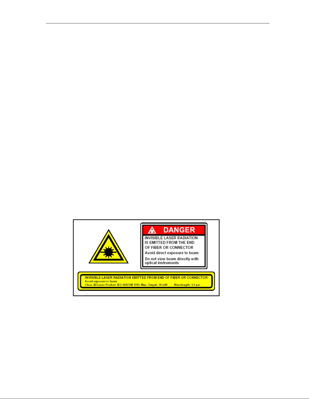
■ Caution: it would be very dangerous to point the Fiber Output Port, from which invisible laser emit,
directly to human body along with the risk of permanent injury to skin or eyes.
■ Make sure the case and the power supply grounded well before turn on the transmitter (grounding
resistance should be less than 4).
■ To get a stable running circumstance for the transmitter, it would be helpful to equip the UPS AC
power supply and air-conditioner.
3
Page 4
CTV-2000 Series Broadcast Transmitter Users’ Manual (REV 1.0)
Chapter 1 Overview
CTV-2000 series 1310 nm broadcast transmitters are important equipments to set up CATV HFC
network, and primarily used for TV video signal, digital TV signal, telephone voice signal and data signal
long-distance fiber transmission. The product utilize imported high performance DFB laser transmitter as
light source and RF power digital automatic process technique, along with advanced RF pre-distortion
circuit developed by Our company. At the same time, built-in microprocessor automatically ensures the
excellent performance of this transmitter.
Chapter 2 Features
■ High performance DFB laser with narrow spectrum and good linearity.
■ With RF power digital automatic process technology, CTV-2000 series 1310 nm broadcast
transmitter can control the laser driving RF power level automatically according to voltage of input
RF signal and number of channels, ensuring the best C/N, CTB and CSO.
■ Excellent pre-distortion technology leads to the improved CTB, CSO and C/N.
■ Built-in microprocessor accurately monitor laser output power and temperature.
■ Front panel VFD screen can real-time display the status parameters and function message.
■ 19″1U standard rack with RS485 and RS232 ports for remote monitor and control.
■ Ethernet port option, support Ethernet-basing network monitoring system.
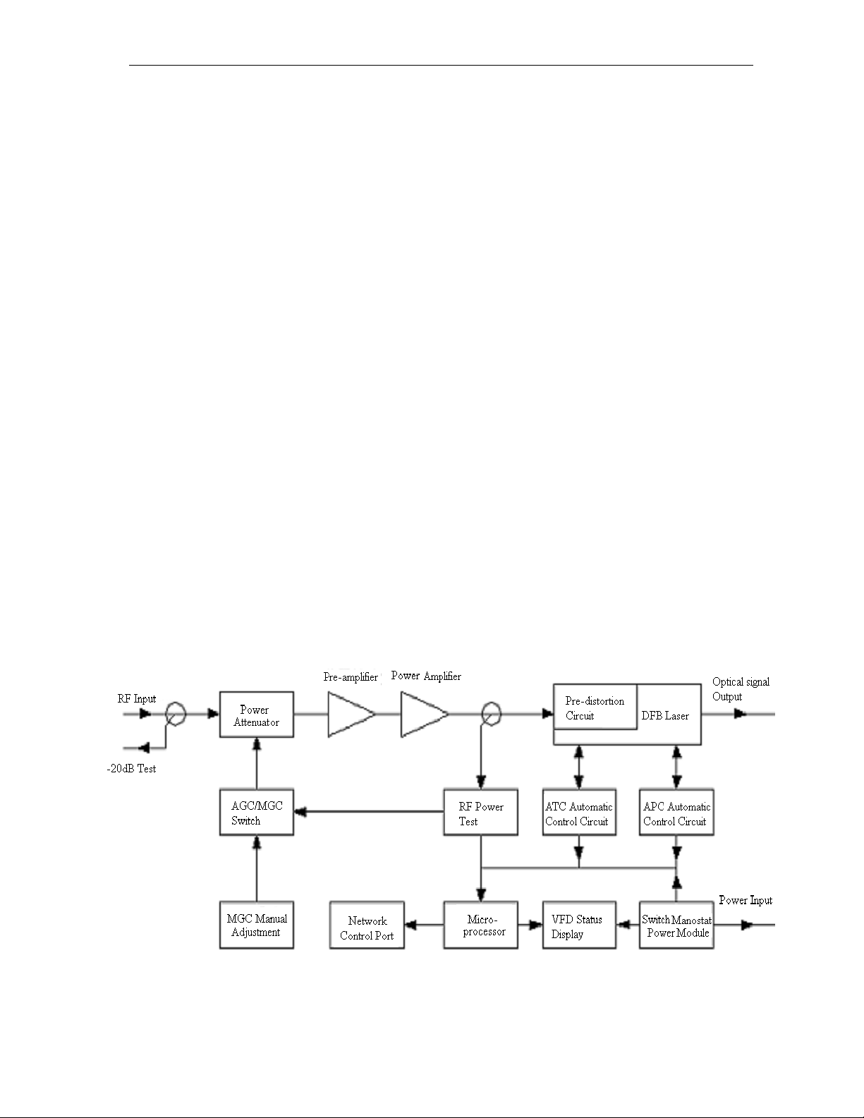
Chapter 3 Internal function block
4
Page 5

CTV-2000 Series Broadcast Transmitter Users’ Manual (REV 1.0)
Chapter 4 Specifications
Item Unit Parameter
Optical Power mW 4 6 8 10 12 14 16 18 20 22
Optical Link Path Loss dB 7 9 10 11 11.8 12.5 13 13.6 14 14.4
Optical Wave Length nm 1310±20
Type of Laser DFB
Optical modulation
Optical connector Type SC/APC
Frequency Range MHz 47~862
RF Input Level dBmV 15~25
Direct Modulation
Flatness In Band dB
RF Input Impedance 75
Input Reflection Loss dB
C/CTB dB
C/CSO dB
C/N dB
AGC Control Range dB
MGC Control Range dB
Power Voltage V AC 90V~265V (50/60 Hz)
Power Consumption W 24
Operation Temperature ˚C 0~45
Store Temperature ˚C -20~65
Relative Humidity % Max 95% no condensation
Dimension mm 433(L) × 325(W) × 44(H)
±0.75
≥16 (47~862)MHz
≥67
≥62
≥51
±5
±5
Optical Link Path C/N Specifications:
Optical Loss(dB)
CTV-2000-04
CTV-2000-06
CTV-2000-08
CTV-2000-10
CTV-2000-12
CTV-2000-14
CTV-2000-16
CTV-2000-18
CTV-2000-20
CTV-2000-22
Test condition: Test link path consists of CTV-2000, standard fiber and standard optical receiver. When
4 5 6 7 8 9 10 11 12 13 14 15 16 17 18
53.8 52.8 51.8 51.0 50.1 49.2 48.2
53.0 52.0 51.0 50.1 49.1 48.1
52.8 51.9 51.0 50.1 49.1 48.2
52.9 51.9 51.0 50.1 49.1 48.2
52.7 51.8 50.8 49.9
52.4 51.5 50.5 49.5
52.0 51.0 50.1 49.1
52.5 51.6 50.6 49.7
51.9 51.0 50.0 49.0
52.2 51.4 50.4 49.4
49.0
48.0
47.8
48.6
48.1
48.7
47.9
48.0
48.6
47.8
optical receiver input optical power is -1dBm, measure CTB, CSO, C/ N under 59 PAL-D channels.
5
Page 6
CTV-2000 Series Broadcast Transmitter Users’ Manual (REV 1.0)
Chapter 5 Function Guide
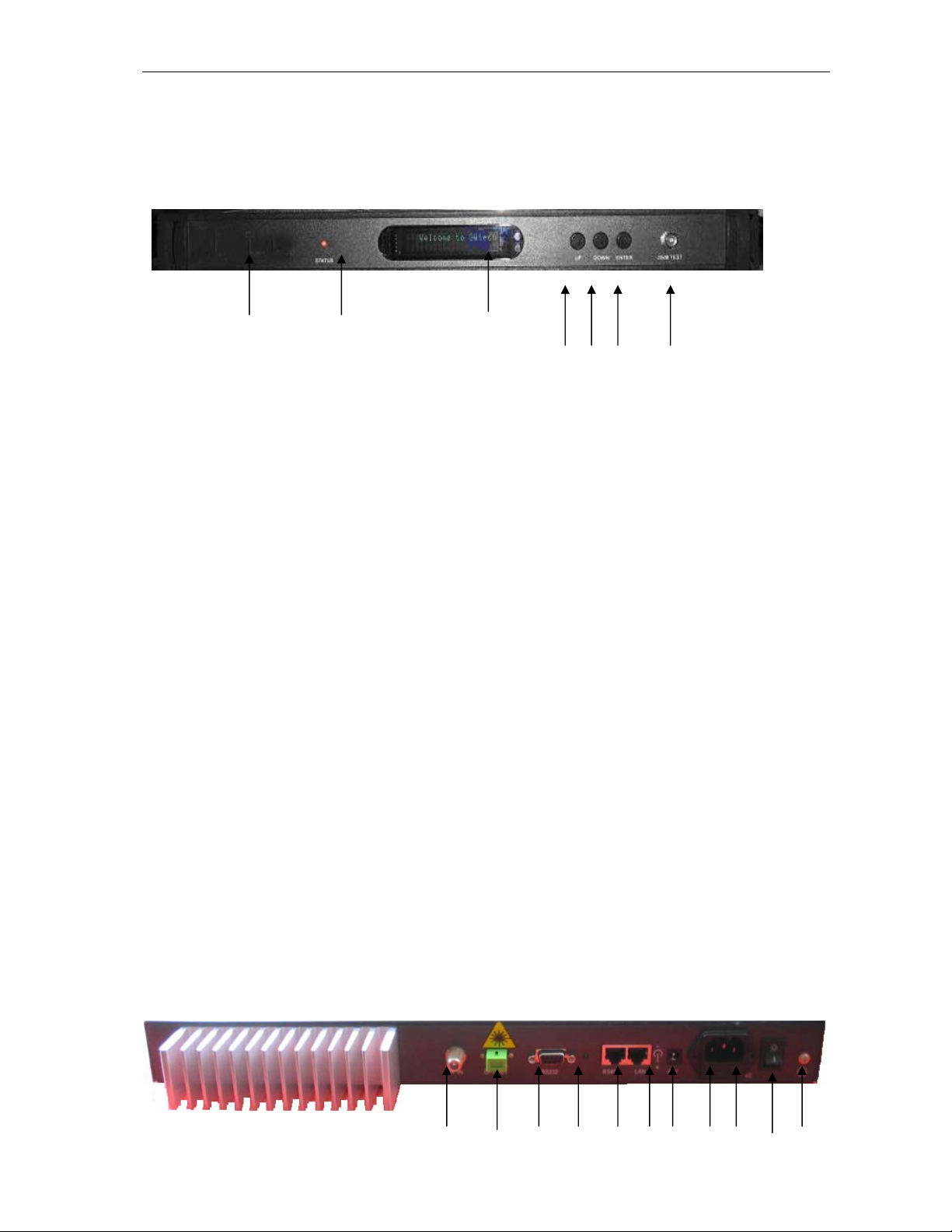
5.1 Front Panel Guide
⑴ ⑵ ⑶ ⑷ ⑸ ⑹ ⑺
Front View
1 CTV-2000 trademark
2 LED status indicator: Green light: normal; Red light: abnormal. User can get message from VFD
monitor to fix the trouble.
3 VFD Monitor: Display each status parameter, product model, delivery series number and other
information of the equipment.
4 UP button: page up the VFD display and increase setting value
5 Down button: page down the VFD display decrease setting value
6 Enter button: MGC mode select and ENTER button.
( Notice: To CTV-2000 transmitter, initial control mode is AGC . If number of channels is less than
15, press UP or DOWN button to shift the VFD display, and press ENTER button when display ‘MOD
LEVEL=XXdBmV’ to select MGC mode. After the selection, VFD display ‘MOD
LEVEL=XXdBmV ’ and ‘Please install…’, enter modulating level setting program in which user can
change modulating level by 1 dBmV by pressing UP or DOWN. When modulating level is changed to
user’s ideal value, press ENTER to make it effected, at that time VFD display ‘MOD
LEVEL=XXdBmV’ and transmitter shift to AGC mode. For instance, if user’s ideal Modulating level
is 42dBmV, VFD would display “MOD LEVEL= 42dBmV” after operations shown above)
7 RF input test port: Standard 75Ω style F metric test port for RF signal on-line test. Level tested from
this port is 20dB less than real input level.
5.2 Rear Panel Guide
⑻ ⑼ ⑽ ⑾ ⑿ ⒀ ⒁ ⒂ ⒃ ⒄ ⒅
6
Page 7

CTV-2000 Series Broadcast Transmitter Users’ Manual (REV 1.0)
Rear View
8 RF input port: Standard 75Ω American style F port, used for connecting RF signal and the equipment.
Level in this input port must be at the range of 15~25dBmV. Too high level may damage laser.
Optimum input level is 20dBmV
*The input level out of range may have chance to damage Laser
9 Optical signal output: Optical signal output port, has two interface: FC/APC and SC/APC. There is
invisible laser from Fiber output when laser works.
*It would be dangerous to point this port to human body especially eyes when equipment works.
10 RS-232 standard network management port: Use for connecting equipment with RS-232 port in
network management server.
11 Network management indicator
12 RS-485 standard network management port: Use for connecting equipment with RS-485 port on
network management server.
13 LAN network management port: Use for connecting equipment with Ethernet-basing network
management server.
14 –48V DC INPUT
15 Power in: Connection the equipment and power.
16 Fuse:AC fuse
17 AC Power switch: Turn on or turn off the power.
18 Case grounding nut :Connecting the equipment and the ground.
5.3 Parameter display
5.3.1 Turning on power display
When turn on power, display ‘Initialize…’ for 2 seconds and buzzer briefly tweet one time indicated
that initialized successfully.
5.3.2 Status display
When the transmitter running after turning on the power, press UP or DOWN button on the front
panel, VFD displays in turn shown below:
① “Welcome to
TV-2000-XX-SC”:module name , SC indicated output port type
② “C
③ “POWER=XX.X mW”: output power, unit mW.
④ “TEMP=XX.X ˚C”: internal temperature value of the laser
⑤ “BIAS= XX mA”: bias current of the laser
MultiDyne”:trademark
7
Page 8

CTV-2000 Series Broadcast Transmitter Users’ Manual (REV 1.0)
⑥ “RF INPUT = XXdBmV”: RF input level
⑦ “ATT= XXdB”: attenuation value
⑧ “MODEL LEVEL= XXdBmV”: modulating level value
⑨ “S/N: xxxx-xx-xxxx”: equipment series number
5.4 Alarm Indication
Display Message Alarm Status System Indication
Warning…!!! Input RF is low Input RF is too low
Warning… !!! Input RF is high Input RF is too high
Chapter 6 Installation & Adjustment
6.1 Opening the cover
• Status indicator red
light flashes
• Status indicator red
light flashes
6.1.1 Inspect the package. If there is any damage or watermark, please contact the freight company or
contact our company.
6.1.2 After unpacking, check equipments and accessories according to packing list. Any question, please
contact local dealer or our company.
6.1.3 If you think equipment has been damaged, please don’t turn on the power and avoid worse damage.
Please contact local dealer or our company.
6.2 Apparatuses & Tools
An optical power meter
A digital multimeter
A frequency analyzer
A standard fiber test jumper (FC/APC or SC/APC)
Waterless alcohol and nosocomial degrease cotton
6.3 Installation
a. Fix equipment on rack and ground the case.
b. Check voltage by digital multimeter in accordance with power requirement and make sure laser lock
is OFF. Then turn on power.
8
Page 9

CTV-2000 Series Broadcast Transmitter Users’ Manual (REV 1.0)
c. Check message on the VFD and the status of front panel LED indicator, push UP and DOWN button to
check each parameter, insure transmitter at normal working status. (Due to no RF input, LED red light,
VFD display: “input RF is low”.)
d. Connect standard fiber test wire to equipment optical signal output, measure output optical power,
affirm output optical power is the same as the value displayed, and has reached setup value. (When
measure optical power, make sure that optical power meter at 1310nm wavelength and that fiber test
jumper is clean.)
e. Measure input RF signal level with a oscillograph or a frequency analysis instrument, make sure that
input RF signal be in the range of 15~25dBmV (optimum value 20dBmV) and connect RF signal to
RF signal input port of the equipment. This time front panel LED turns to green and VFD displays RF
input value as “RF INPUT = XXdBmV”.
(Notice: get the real RF input value, press UP or DOWN button to shift the VFD display, and press
ENTER button when display ‘RF LEVEL=XXdBmV’ to enter input level setting program when
VFD display ‘MOD LEVEL=XXdBmV’ and ‘Please install…’, in this setting program user can set
RF input level by 1 dBmV by pressing UP or DOWN button. when setting level equal real value,
press ENTER to make it effected, at that time VFD display ‘RF LEVEL=XXdBmV’. For instance, if
real RF input level is 20dBmV, VFD would display “RF LEVEL= 20dBmV” after operations
shown above)
f. Re-measure optical output power, make sure that optical output power being normal, remove standard
fiber test jumper and optical power meter, connect the equipment to network and end the installation.
Chapter 7 Clean & Maintenance
Each fiber connector maybe polluted by dust or dirt in the operation process, which results in optical
link loss increase. If optical receive power and output level of the receiver decline, you should clean and
maintain fiber active connector. The clean methods are recommended below:
a. Carefully screw off fiber active connector from the adapter avoids the fiber active connector with
laser to aim at the human body or eye resulting in harm.
b. Use nosocomial degrease alcohol cotton to wash carefully, after finish, still need to be waited 1~2
minutes until active connector surface dry in the air.
9
Page 10

CTV-2000 Series Broadcast Transmitter Users’ Manual (REV 1.0)
c. When the cleaned optical active connector screwed back to adapter, it should be noticed that we
should make force slowly to avoid china tube crack in the adapter.
d. The fiber active connector should be cleaned in two ends. If optical power is still low after clean,
cleaning the other end of the fiber is recommended. If optical power is still low after clean the two
ends, it is recommended that clean the inner adaptor. (Take care of the fiber when disassembly the
adaptor).
e. Use compressed air or degrease alcohol cotton to wash the adapter carefully. When use compressed
air, aim the muzzle at china tube of the adapter, clean the china tube with compressed air. When use
alcohol cotton, the insert direction need to be consistent, otherwise, user can’t reach a good clean
effect.
Notice:
1. Avoid laser aiming at the human body or eyes that can result in harm.
2. Assembly the fiber adaptor with gentle action to prevent the china tube inside the adaptor from
breaking up.
Chapter 8 After-sale customer service
a. Our commitment: One year free trouble fixing service and life-long customer service (1 year free
guarantee time start from the date indicated in products S/N attaching on side of products).
b. If the equipment failed, please contact immediately local dealer or our customer service centre.
c. Don’t try to fix the equipment trouble without the help from technician, it may lead to worse trouble.
d. Notice: There are adhesive tape seals on both sides of the case. Any unauthorized remove to this tape
seal by user will end our free customer service even in guarantee time.
10
Page 11

CTV-2000 Series Broadcast Transmitter Users’ Manual (REV 1.0)
y
Chapter 9 Troubleshooting
SYMPTOM FAULT ACTION
No VFD or LED display
after turn on the power
After turn on the power,
VFD monitor and LED
normal, but optical output
power low.
After connecting to
network, figure of optical
connector has obvious
noise point.
After connecting to
network, some channels
figure of optical
connector has obvious
noise point.
After connecting to
network, optical
connector figure has
obvious ripple.
Switching power abnormally start
and equipment DC power supply
1. Check jumper quality
2. Polluted optical active
connector or adapter
3. Damaged china tube in
adapter maybe
1. Optical connector receive
optical power not enough
cause C/N drop.
2. RF input level too low for
laser to modulate
3. System link path C/N too low.
Some channels C/N too low.
1. Receive optical power in
optical connector too high to
RF signal alternate modulate
parameter going bad.
2. Input optical transmitter RF
signal alternate modulate
parameter too bad.
abnormal.
Check power supply whether normal
(AC90V~250V), if power voltage
normal, most cause is switch power
module fault, contact dealer or our
compan
1. Alternate an good test jumper
2. Clean polluted fiber active
3. Alternate damaged adapter
1. Clean fiber active connector or
2. Check optical link path and input
3. Make sure RF input level within
1. Check received optical power at
2. Check input optical transmitter
3. Make sure RF input level within
.
connector or adapter
adapter to reset optical connector
receiver optical power (According
to chapter 7 The clean and
maintenance).
optical transmitter RF signal,
adjust system C/N to higher than
51dB.
the range (15~25dBmV)
3. Check the channel signal
C/N
4. Check the flatness of RF
input signal
optical connector and properly
adjust.
signal alternate modulate
parameter and properly adjust.
the range (15~25dBmV)
11
Page 12

CTV-2000 Series Broadcast Transmitter Users’ Manual (REV 1.0)
CTV2000-FRX
Users’ Manual
Ve rsion 1. 0
12
Page 13

CTV-2000 Series Broadcast Transmitter Users’ Manual (REV 1.0)
t
TTaabbllee ooff CCoonntteennt
CChhaapptteerr 11
Preface .......................................................................................................14
TTaabbllee ooff CCoonntteennt
t .........................................................................................................13
Chapter 2 Description ................................................................................................15
Chapter 3 Features .....................................................................................................15
Chapter 4 Specifications: ...........................................................................................15
Chapter 5 Accessory ...................................................................................................16
Chapter 6 Installation & Adjustment .......................................................................16
6.1 Opening the cover ............................................................................................................. 16
6.2 Apparatuses & Tools ......................................................................................................... 16
6.3 Installation ....................................................................................................................... .. 16
Chapter 7 Clean & Maintenance ..............................................................................17
Chapter 8 After-sale customer service .....................................................................17
13
Page 14

CTV-2000 Series Broadcast Transmitter Users’ Manual (REV 1.0)
CChhaapptteerr 11
This manual states CTV2000-FRX FTTH optical receiver product feature, specification, installation,
adjustment and maintenance. To install this receiver successfully and use it safely, users should read the
manual carefully before installation, and perform the installation and adjustment in accordance with this
manual. Otherwise, some practices or circumstances may lead to damage or personal injury. Please
contact MULTIDYNE if any question.
Important user information:
■ Caution: There would be invisible laser from the fiber output port, which may cause permanent injury
to human skin and eyes. Please do not point the fiber connector to the skin. In any case it is strictly
forbidden to point the fiber connector to the eyes.
■ The input optical power shall be –8~+3dBm, strong optical power may damage the photodiode.
■ Make sure the case and the power supply grounded well before turning on the receiver (grounding
resistance should be less than 4), prevent the static from damaging photodiode and injuring user.
■ To get a stable running circumstance for the receiver, it would be useful for the users in regions
without steady electricity to equip the AC power supply (UPS would be better).
Preface
The CTV2000-FRX optical node has the Aluminum housing, which has an excellent heat dissipation
performance.
14
Page 15

CTV-2000 Series Broadcast Transmitter Users’ Manual (REV 1.0)
Chapter 2 Description
CTV2000-FRX Optical Receiver is designed for PON FTTH broadband analog or digital CATV
services. Working at extremely low optical input power, CTV2000-FRX still generates excellent CATV
signals for home subscribers.
1) Optical Input SC/APC Adaptor
2) RF Output
3) Power Indicator
1) 2) 3)
Chapter 3 Features
High Linearity Photodiode
1000MHz Bandwidth
Low noise GaAs Amplifier
Compact Housing
12V DC External Power Supply
Chapter 4 Specifications:
Item Parameter
Input Optical Wavelength 1000~1600 nm
Working Optical Power +2 ~ -8 dBm
Optical Connector SC/APC
Optical Return Loss 60 dB
RF Bandwidth 45 ~ 1000 MHz
RF Connector Metric F or American F
RF Output Impedance 75
RF Output Level 20dBmV @ -5dBm input optical Power
RF Flatness ± 0.75dB
RF Return Loss >16 dB
CNR >47 dBc @ -5dBm input optical power
CSO <-70 dBc @77ch NTSC
CTB <-70 dBc @77ch NTSC
Power Supply 12 V DC, Power Adapter Meet UL or CE or PSE or CCC
Power Consumption < 3.5W
Wor ki ng Temperature -40 ~ +60
Dimension (L*W*H) 85mm×80mm×28mm
Weight 0.25 Kg (not including power adapter)
Test condition:
Input 59 channels PAL-D signal to standard optical transmitter and measure the optical receiver C/CTB,
C/CSO and C/N in conditions of -5dBm optical input (10km fiber + optical attenuator) and 20dBmV RF
output.
15
Page 16

CTV-2000 Series Broadcast Transmitter Users’ Manual (REV 1.0)
Chapter 5 Accessory
12V DC Adaptor: 1pcs
Users’ Manual: 1pcs
Chapter 6 Installation & Adjustment
6.1 Opening the cover
6.1.1 Inspect the package. If there is any damage or watermark, please contact the freight company or
MULTIDYNE.
6.1.2 After unpacking, check equipments and accessories according to packing list. Any question, please
contact local dealer or MULTIDYNE.
6.1.3 If you think equipment has been damaged, please don’t turn on the power and contact local dealer or
MULTIDYNE.
6.2 Apparatuses & Tools
An optical power meter
A digital multimeter
A frequency analyzer
A standard fiber test jumper (FC/APC or SC/APC or SC/UPC)
Waterless alcohol and nosocomial degrease cotton
6.3 Installation
c. Check input optical power with optical power meter. Making sure that the input power in the range
of -2dBm~-8dBm. -5dBm optical power input is recommended.
d. Insert the input fiber cable to the fiber input port. Clean the connector. Fix the fiber connector with
the fiber adaptor after confirming the input optical power is normal.
e. Connect the RF output port with coaxial cable. The optical receiver installation is finished.
Troubleshooting during installation
a) RF Output Low: check the connection of RF adaptor and the coaxial cable.
b) No RF Output: check the power indicator. If power is on, check the optical input power in the
recommended range.
c) Cautions:
1) There might be invisible laser beam from fiber pigtail, which might cause permanent injury to
16
Page 17

CTV-2000 Series Broadcast Transmitter Users’ Manual (REV 1.0)
human eyes.
2) Make sure fiber connector and RF connector are clean and in good shape.
Chapter 7 Clean & Maintenance
Each fiber connector maybe polluted by dust or dirt in the operation process, which results in optical
link loss increase. If optical receive power and output level of the receiver decline, you should clean and
maintain fiber active connector. The clean methods are recommended below:
f. Carefully screw off fiber active connector from the adapter avoids the fiber active connector with
laser to aim at the human body or eye.
g. Use nosocomial degrease alcohol cotton to wash carefully, after finish, still need to be waited 1~2
minutes until active connector surface dry in the air.
h. When the cleaned optical active connector screwed back to adapter, it should be noticed that we
should make force slowly to avoid china tube crack in the adapter.
i. The fiber active connector should be cleaned in two ends. If optical power is still low after clean,
cleaning the other end of the fiber is recommended. If optical power is still low after clean the two
ends, it is recommended that clean the inner adaptor. (Take care of the fiber when disassembly the
adaptor).
j. Use compressed air or degrease alcohol cotton to wash the adapter carefully. When use compressed
air, aim the muzzle at china tube of the adapter; clean the china tube with compressed air. When use
alcohol cotton, the insert direction need to be consistent, otherwise, user can’t reach a good clean
effect.
Notice:
a) Avoid laser aiming at the human body or eyes, which may result in permanent injury.
b) Assembly the fiber adaptor with gentle action so as to prevent the china tube inside the adaptor
from breaking up.
Chapter 8 After-sale customer service
e. Warranty: One year free trouble fixing service and life-long customer service (1 year free guarantee
time start from the date indicated in products S/N attaching on side of products).
17
Page 18

CTV-2000 Series Broadcast Transmitter Users’ Manual (REV 1.0)
f. If the equipment failed, please contact immediately local dealer or MULTIDYNE. Don’t try to fix the
equipment trouble without the guidance from technician; it may lead to worse trouble.
18
 Loading...