

Page 1
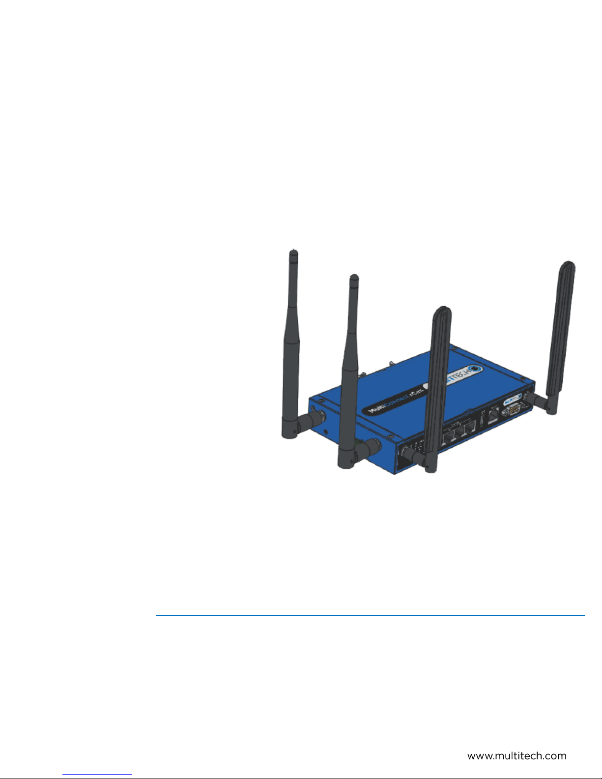
MultiConnect
Series Router User Guide
®
rCell 500
Page 2

COPYRIGHT
MultiConnect®rCell 500 Series Router User Guide
Model: MTR5-LEU2 Version 1.0
Part Number: S000589
Copyright
This publication may not be reproduced, in whole or in part, without the specific and express prior written permission signed by an executive officer of
Multi-Tech Systems, Inc. All rights reserved. Copyright © 2015 by Multi-Tech Systems, Inc.
Multi-Tech Systems, Inc. makes no representations or warranties, whether express, implied or by estoppels, with respect to the content, information,
material and recommendations herein and specifically disclaims any implied warranties of merchantability, fitness for any particular purpose and noninfringement.
Multi-Tech Systems, Inc. reserves the right to revise this publication and to make changes from time to time in the content hereof without obligation of
Multi-Tech Systems, Inc. to notify any person or organization of such revisions or changes.
Legal Notices
The MultiTech products are not designed, manufactured or intended for use, and should not be used, or sold or re-sold for use, in connection with
applications requiring fail-safe performance or in applications where the failure of the products would reasonably be expected to result in personal injury or
death, significant property damage, or serious physical or environmental damage. Examples of such use include life support machines or other life
preserving medical devices or systems, air traffic control or aircraft navigation or communications systems, control equipment for nuclear facilities, or
missile, nuclear, biological or chemical weapons or other military applications (“Restricted Applications”). Use of the products in such Restricted
Applications is at the user’s sole risk and liability.
MULTITECH DOES NOT WARRANT THAT THE TRANSMISSION OF DATA BY A PRODUCT OVER A CELLULAR COMMUNICATIONS NETWORK WILL BE
UNINTERRUPTED, TIMELY, SECURE OR ERROR FREE, NOR DOES MULTITECH WARRANT ANY CONNECTION OR ACCESSIBILITY TO ANY CELLULAR
COMMUNICATIONS NETWORK. MULTITECH WILL HAVE NO LIABILITY FOR ANY LOSSES, DAMAGES, OBLIGATIONS, PENALTIES, DEFICIENCIES, LIABILITIES,
COSTS OR EXPENSES (INCLUDING WITHOUT LIMITATION REASONABLE ATTORNEYS FEES) RELATED TO TEMPORARY INABILITY TO ACCESS A CELLULAR
COMMUNICATIONS NETWORK USING THE PRODUCTS.
The MultiTech products and the final application of the MultiTech products should be thoroughly tested to ensure the functionality of the MultiTech
products as used in the final application. The designer, manufacturer and reseller has the sole responsibility of ensuring that any end user product into
which the MultiTech product is integrated operates as intended and meets its requirements or the requirements of its direct or indirect customers.
MultiTech has no responsibility whatsoever for the integration, configuration, testing, validation, verification, installation, upgrade, support or maintenance
of such end user product, or for any liabilities, damages, costs or expenses associated therewith, except to the extent agreed upon in a signed written
document. To the extent MultiTech provides any comments or suggested changes related to the application of its products, such comments or suggested
changes is performed only as a courtesy and without any representation or warranty whatsoever.
Contacting MultiTech
Knowledge Base
The Knowledge Base provides immediate access to support information and resolutions for all MultiTech products. Visit http://www.multitech.com/kb.go.
Support Portal
To create an account and submit a support case directly to our technical support team, visit: https://support.multitech.com.
Support
Business Hours: M-F, 8am to 5pm CT
Country By Email By Phone
Warranty
To read the warranty statement for your product, visit www.multitech.com/warranty.go. For other warranty options, visit www.multitech.com/es.go.
World Headquarters
Multi-Tech Systems, Inc.
2205 Woodale Drive, Mounds View, MN 55112
Phone: (800) 328-9717 or (763) 785-3500
Fax (763) 785-9874
2 MultiConnect®rCell 500 Series Router User Guide
Page 3

CONTENTS
Contents
MultiConnect®rCell 500 Series Router User Guide ................................................................................................... 2
Product Overview .................................................................................................................................................... 6
Package Contents .................................................................................................................................................... 7
System Requirements .............................................................................................................................................. 9
LED Indicators ........................................................................................................................................................ 10
Specifications......................................................................................................................................................... 11
RF Specifications .................................................................................................................................................... 13
Installing and Using the Router .............................................................................................................................. 14
Installing SIM Cards..................................................................................................................................................... 14
Attaching Cables and Antennas .................................................................................................................................. 15
Using Setup Wizard..................................................................................................................................................... 16
VPN Setup Wizard ....................................................................................................................................................... 16
Basic Network........................................................................................................................................................ 18
Basic Network ............................................................................................................................................................. 18
WAN Setup................................................................................................................................................................ 18
Physical Interface ...................................................................................................................................................... 18
Internet Setup ........................................................................................................................................................... 19
Internet Setup for 3G/4G WAN ................................................................................................................................ 19
Internet Setup for Ethernet WAN............................................................................................................................. 21
Static IP ..................................................................................................................................................................... 21
Dynamic IP ................................................................................................................................................................ 21
PPP over Ethernet ..................................................................................................................................................... 22
PPTP .......................................................................................................................................................................... 22
L2TP........................................................................................................................................................................... 22
Internet Setup - WiFi WISP WAN.............................................................................................................................. 23
Load Balance ............................................................................................................................................................. 23
LAN and VLAN Setup................................................................................................................................................... 24
Ethernet LAN............................................................................................................................................................. 24
VLAN.......................................................................................................................................................................... 24
Port-Based VLAN ....................................................................................................................................................... 24
Tag-Based VLAN ........................................................................................................................................................ 25
Port Speed................................................................................................................................................................. 25
WiFi Setup ................................................................................................................................................................... 25
AP Router Mode........................................................................................................................................................ 25
WDS Hybrid Mode .................................................................................................................................................... 26
WDS Only Mode........................................................................................................................................................ 27
MultiConnect®rCell 500 Series Router User Guide 3
Page 4

CONTENTS
Wireless Client List.................................................................................................................................................... 28
Advanced Configuration............................................................................................................................................ 28
IPv6 Setup ................................................................................................................................................................... 28
Static IPv6.................................................................................................................................................................. 29
DHCPv6...................................................................................................................................................................... 29
PPPoE ........................................................................................................................................................................ 29
6 to 4 ......................................................................................................................................................................... 30
6 in 4 ......................................................................................................................................................................... 30
NAT Setup ................................................................................................................................................................... 30
NAT Loopback ........................................................................................................................................................... 30
Virtual Server ............................................................................................................................................................ 30
Virtual Computers..................................................................................................................................................... 30
Special AP.................................................................................................................................................................. 31
DMZ........................................................................................................................................................................... 31
Routing Setup.............................................................................................................................................................. 31
Static Routing............................................................................................................................................................ 31
Dynamic Routing....................................................................................................................................................... 31
Routing Information.................................................................................................................................................. 31
Client/Server ............................................................................................................................................................... 32
Dynamic DNS............................................................................................................................................................. 32
DHCP Server .............................................................................................................................................................. 32
Serial Port .................................................................................................................................................................... 33
Port Configuration..................................................................................................................................................... 33
Virtual COM............................................................................................................................................................... 33
TCP Client Mode........................................................................................................................................................ 33
TCP Server Mode....................................................................................................................................................... 34
UDP Mode................................................................................................................................................................. 34
RFC2217 Mode.......................................................................................................................................................... 34
Modbus ..................................................................................................................................................................... 35
Advanced Network ................................................................................................................................................ 36
Firewall........................................................................................................................................................................ 36
Packet Filters............................................................................................................................................................... 36
URL Blocking................................................................................................................................................................ 36
Web Content Filters .................................................................................................................................................... 37
MAC Control................................................................................................................................................................ 37
IPS (Intrusion Prevention Systems)............................................................................................................................. 37
Options........................................................................................................................................................................ 37
Quality of Service................................................................................................................................................... 39
QoS Configuration....................................................................................................................................................... 39
Rule-based QoS ........................................................................................................................................................... 39
Create a QoS Rule ....................................................................................................................................................... 39
4 MultiConnect®rCell 500 Series Router User Guide
Page 5

CONTENTS
VPN Setup.............................................................................................................................................................. 41
VPN using IPSec........................................................................................................................................................... 41
Dynamic IP VPN........................................................................................................................................................... 41
IPSec-IKE Setting ......................................................................................................................................................... 42
IPSec-Manual Setting .................................................................................................................................................. 43
VPN using PPTP Server................................................................................................................................................ 44
VPN using PPTP Client................................................................................................................................................. 45
VPN using L2TP Server ................................................................................................................................................ 45
VPN using L2TP Client ................................................................................................................................................. 45
GRE Tunnel.................................................................................................................................................................. 46
Redundancy ........................................................................................................................................................... 47
VRRP............................................................................................................................................................................ 47
System Management ............................................................................................................................................. 48
TR-069 ......................................................................................................................................................................... 48
SNMP........................................................................................................................................................................... 48
CLI (command line interface)...................................................................................................................................... 48
Applications........................................................................................................................................................... 50
Mobile Application...................................................................................................................................................... 50
Remote Management ................................................................................................................................................. 51
Captive Portal.............................................................................................................................................................. 52
System................................................................................................................................................................... 53
Change Password ........................................................................................................................................................ 53
System Information..................................................................................................................................................... 53
System Tools ............................................................................................................................................................... 53
Scheduling ................................................................................................................................................................... 54
External Servers .......................................................................................................................................................... 54
Safety Warnings..................................................................................................................................................... 55
Ethernet Ports ............................................................................................................................................................. 55
Radio Frequency (RF) Safety ....................................................................................................................................... 55
Interference with Pacemakers and Other Medical Devices ...................................................................................... 55
Potential interference............................................................................................................................................... 55
Precautions for pacemaker wearers ........................................................................................................................ 55
Regulatory Information.......................................................................................................................................... 57
EMC, Safety, and R&TTE Directive Compliance ......................................................................................................... 57
Restriction of the Use of Hazardous Substances (RoHS) ............................................................................................ 58
Waste Electrical and Electronic Equipment Statement .............................................................................................. 58
WEEE Directive .......................................................................................................................................................... 58
Instructions for Disposal of WEEE by Users in the European Union ........................................................................ 58
Information on HS/TS Substances According to Chinese Standards ......................................................................... 60
Information on HS/TS Substances According to Chinese Standards (in Chinese) ...................................................... 61
MultiConnect®rCell 500 Series Router User Guide 5
Page 6

PRODUCT OVERVIEW
Product Overview
This guide decribes the MultiConnect rCell 500 Series Router. The MultiConnect rCell 500 offers secure data
communication between different types of devices. It features redundant power supplies and dual SIM capability
for a more reliable connection
6 MultiConnect®rCell 500 Series Router User Guide
Page 7
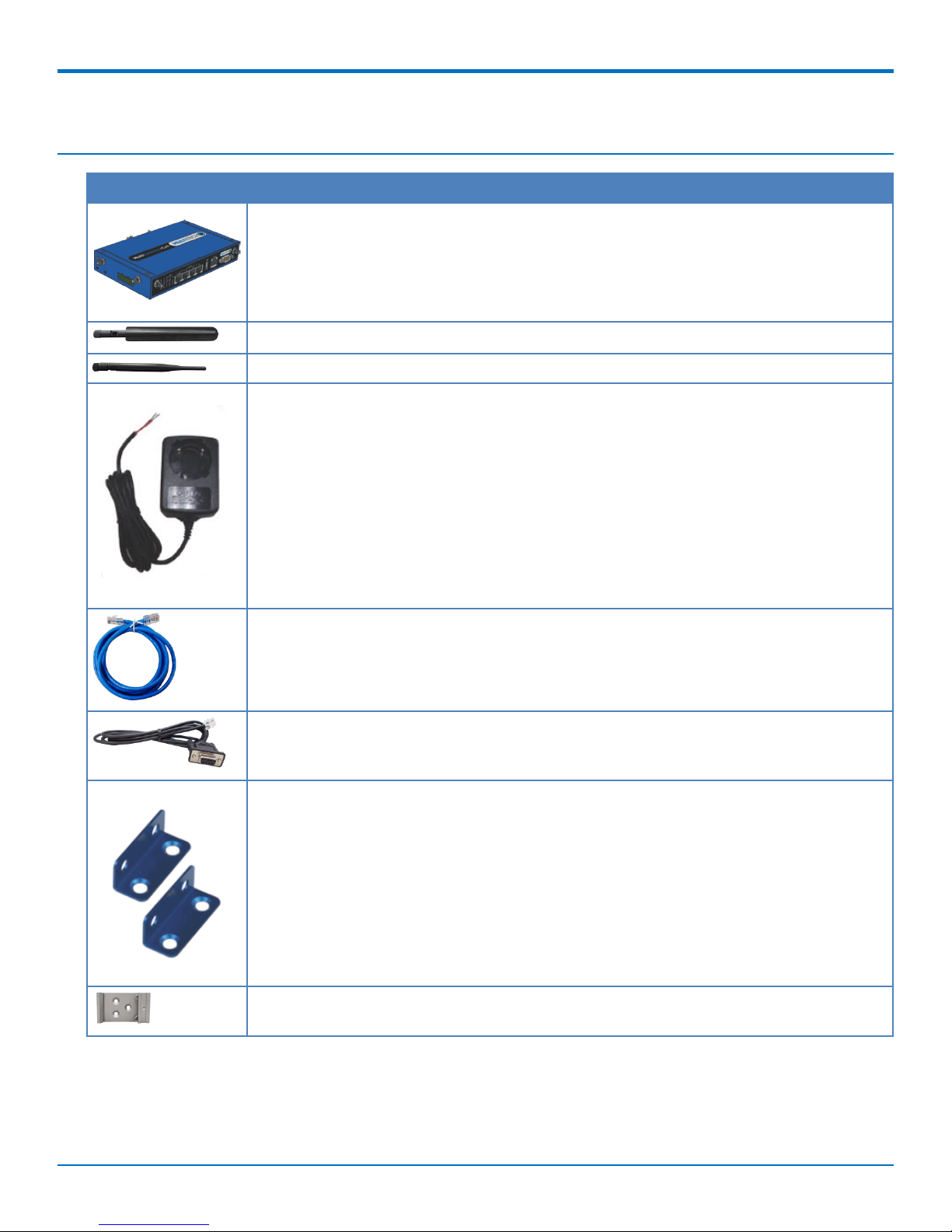
Package Contents
Contents Description
One MultiConnect rCell 500
Two 4G Antennas
Two WiFi Antennas
One Power Adapter (DC12V/2A). The maximum power consumption is 15.5W.
PACKAGE CONTENTS
One RJ-45 Cable
One Console Cable
Two Wall Mount Kits
One DIN-Rail Bracket
MultiConnect®rCell 500 Series Router User Guide 7
Page 8
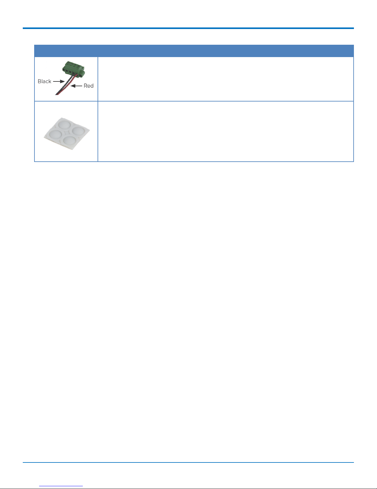
PACKAGE CONTENTS
Contents Description
Power Port
Four Rubber Feet
8 MultiConnect®rCell 500 Series Router User Guide
Page 9

System Requirements
Network Requirements ■ An Ethernet RJ-45 cable or DSL modem
■ 4G cellular service subscription
■ 802.11b/g/n wireless clients
■ Ethernet connection
Configuration Utility Requirements ■ Operating System Requirements
■ Windows®XP with SP2 or higher
■ Macintosh
■ Linux-based operating system
■ Browser Requirements
■ Internet Explorer 9.0 or higher
■ Chrome 2.0 or higher
■ Firefox 3.0 or higher
■ Safari 3.0 or higher
SYSTEM REQUIREMENTS
MultiConnect®rCell 500 Series Router User Guide 9
Page 10
LED INDICATORS
LED Indicators
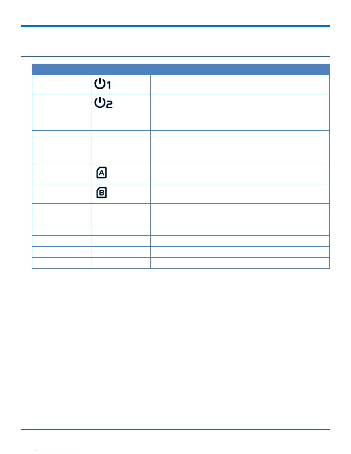
Indicator Label Description
Power Source 1 Continuously ON: Device is powered by source 1.
Power Source 2 Continuously ON: Device is powered by source 2.
Note: If both power source 1 and 2 are connected, the
device will choose power source 1 first. In this instance,
the LED for power source 2 will remain OFF.
WLAN (WiFi) WIFI Continuously ON: Wireless radio is enabled.
Flashing: Data packets are being transferred.
OFF: Wireless radio is disabled.
SIM A Continuously ON: SIM A is in use.
SIM B Continuously ON: SIM B is in use.
LAN1 - LAN 4 E1 - E4 Continuously ON: Ethernet connection is established.
Flashing: Data packets are being transferred.
High 4G Signal HIGH Continuously ON: Strong 4G signal strength.
Low 4G Signal LOW Continuously ON: Weak 4G signal strength.
USB USB CELL Continuously ON: USB device is attached.
Serial Port SER. Flashing: Serial data is being transferred.
10 MultiConnect®rCell 500 Series Router User Guide
Page 11

Specifications
MTR5-LEU2
Category Description
General
SPECIFICATIONS
Performance
Frequency Bands
Radio
Cellular
Wi-Fi
4G LTE Speed
Packet Data
SMS
SMS
Connectors
Cellular
WiFi
LTE, HSPA+GSM/GPRS/EDGE
LTE FDD: B1/B2/B3/B5/B7/B8/B20
HSPA+ Band: 850/900/1900/2100 MHz GSM/GPRS/EDGE Band:
850/900/1800/1900 MHz
4G LTE Radio
802.11 b/g/n
1
Up to 100 Mbps downlink/50 Mbps uplink
Point-to-Point Messaging Mobile-Terminated SMS Mobile-Originated SMS
Two Female SMA connectors for cellular
Two Reverse polarity male SMA connector for Wi-Fi
SIM Holder
Two Mini-SIM 2FF, standard 1.8 V and 3 V SIM receptacle
Power Requirements
Voltage
9 V to 48 V DC
Physical Description
Dimensions
Weight
Dimensions are shown in the section “Dimensions” that follows.
TBD
Environment
-10° C to +60° C
Operating Temperature
Humidity
2
Relative humidity 15% to 93% non-condensing
Certifications, Compliance, Warranty
EU Compliance
R&TTE
MultiConnect®rCell 500 Series Router User Guide 11
Page 12

SPECIFICATIONS
Category Description
Safety Compliance
Network Compliance
Warranty
1
The radio’s performance may be affected at the temperature extremes. This is considered normal. There is no
IEC 60950-1
GCF
Two years
single cause for this function. It is the result of an interaction of several factors, such as the ambient temperature,
the operating mode, and the transmit power.
2
UL Recognized @0° C to 40° C, Limited by DC Power Supply.
12 MultiConnect®rCell 500 Series Router User Guide
Page 13

RF Specifications
Operating Band Tx Rx
UMTS Band I 1920 MHz - 1980 MHz 2110 MHz - 2170 MHz
UMTS Band II 1850 MHz - 1910 MHz 1930 MHz - 1990 MHz
UMTS Band V 824 MHz - 849 MHz 869 MHz - 894 MHz
UMTS Band VIII 880 MHz - 915 MHz 925 MHz - 960 MHz
GSM 850 824 MHz - 849 MHz 869 MHz - 894 MHz
GSM 900 880 MHz - 915 MHz 925 MHz - 960 MHz
GSM 1800 (DCS) 1710 MHz - 1785 MHz 1805 MHz - 1880 MHz
GSM 1900 (PCS) 1850 MHz - 1910 MHz 1930 MHz - 1990 MHz
LTE Band I 1920 MHz - 1980 MHz 2110 MHz - 2170 MHz
LTE Band II 1850 MHz - 1910 MHz 1930 MHz - 1990 MHz
RF SPECIFICATIONS
LTE Band III 1710 MHz - 1785 MHz 1805 MHz - 1880 MHz
LTE Band V 824 MHz - 849 MHz 869 MHz - 894 MHz
LTE Band VII 2500 MHz - 2570 MHz 2620 MHz - 2690 MHz
LTE Band VIII 880 MHz - 915 MHz 925 MHz - 960 MHz
LTE Band XX 832 MHz - 862 MHz 791 MHz - 821 MHz
MultiConnect®rCell 500 Series Router User Guide 13
Page 14
INSTALLING AND USING THE ROUTER
Installing and Using the Router
Installing SIM Cards
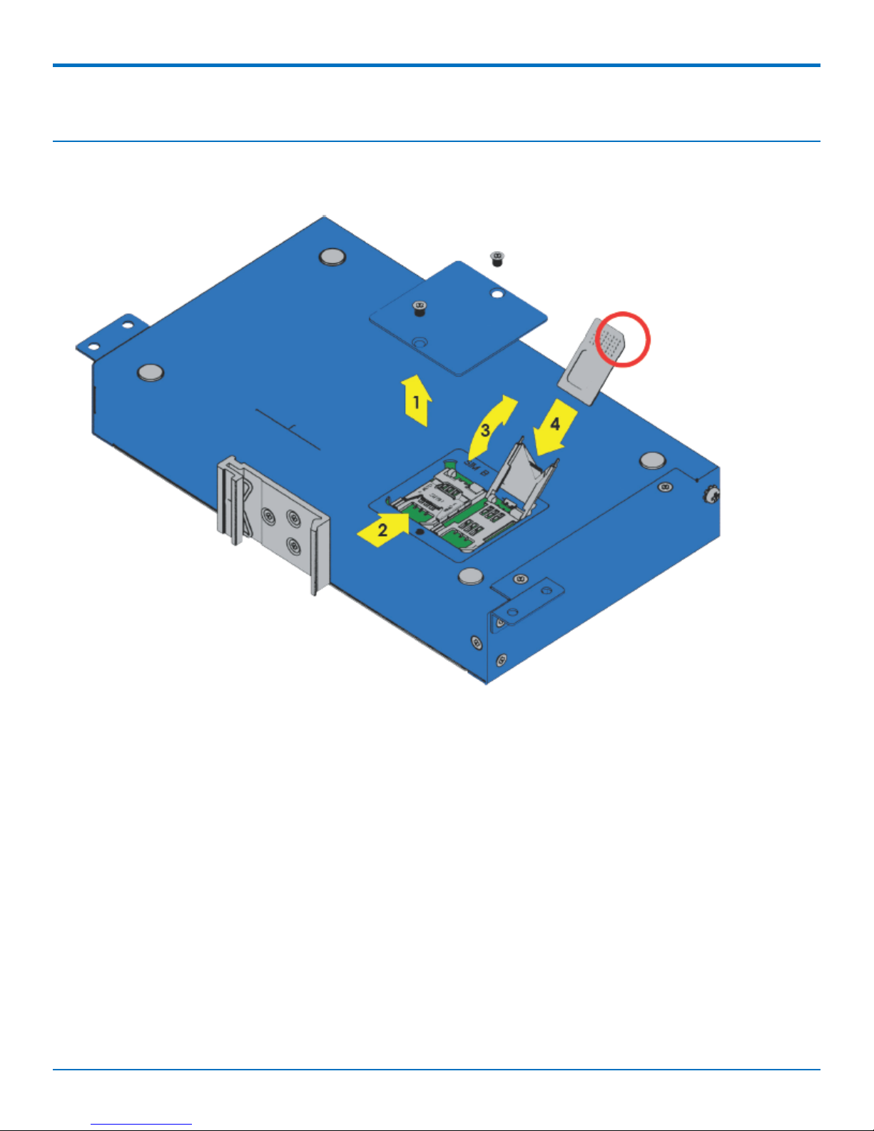
The SIM card slots are located on the bottom of the device.
Note: Before installing or changing the SIM card, make sure the device is turned OFF and power is
disconnected.
1. Unscrew and remove SIM card cover.
2. Slide SIM card socket toward hinge to unlock.
3. Lift up SIM holder and insert SIM card, making sure notch is lined up correctly.
4. Lay SIM holder down.
5. Slide SIM socket away from hinge to lock.
6. Replace SIM card cover.
14 MultiConnect®rCell 500 Series Router User Guide
Page 15
Attaching Cables and Antennas
INSTALLING AND USING THE ROUTER
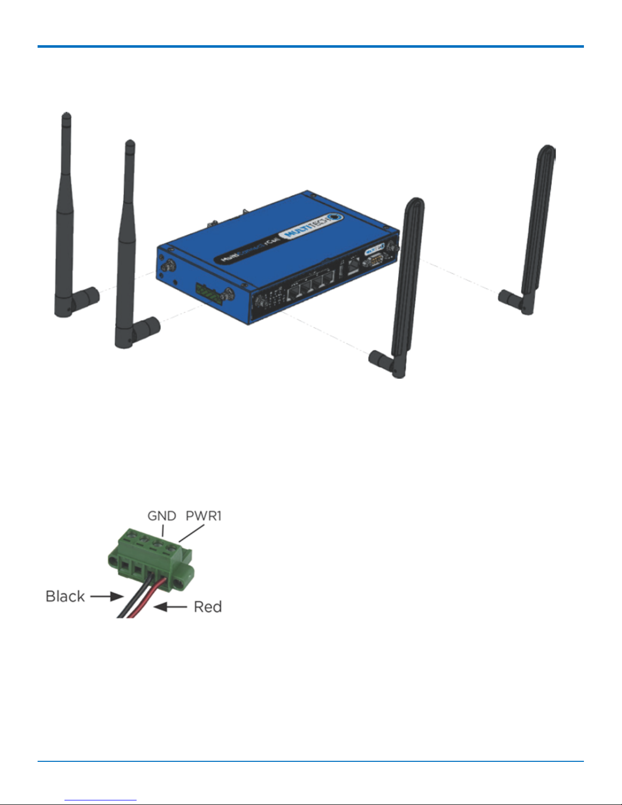
1. Attach 4G antennas to the device's front panel by screwing them into the designated connectors.
2. Attach WiFi antennas to the device's side panel by screwing them into the designated connectors.
3. Attach cables to their corresponding ports on the device's front panel.
Note: During configuration use ports E2 to E4 only. DO NOT attach Ethernet cable to E1/WAN port.
4. Attach red wire on the power cable to PWR1 and the black wire to the GND for PWR1 on the power port
on the device's side panel.
MultiConnect®rCell 500 Series Router User Guide 15
Page 16

INSTALLING AND USING THE ROUTER
Using Setup Wizard
If you are using a 3G/4G network, verify SIM card has been installed before starting setup. Configure this device
using the web UI. To access the web UI, enter the IP Address into your browser. The default IP Address is
192.168.2.1. If this has been changed, type in the new IP Address. On the login page, type the administrator
password and click Login.
Note: The default administrator username and password is admin.
After logging in, select the appropriate language. From the menu on the left, click Wizard.
1. To start the Wizard, click Next.
2. Change the web UI login password. Click Next. (We strongly recommend changing the default password.)
3. Select the correct Time Zone. Click Next. If auto detection does not work, click Detect Again and select
manually.
4. Select the WAN type and address. For fixed line, choose Ethernet WAN. Click Next.
■ If you select Ethernet (Static IP Address), input all your ISP-provided addresses (fixed IP
address). Click Next.
■ If you select Ethernet (Dynamic IP Address), leave input blank if not required. If your ISP
requires input, enter host name or registered MAC addresses. Click Next.
■ If you select Ethernet (PPPoE or PPP over Ethernet), input account and password from your
ISP. Use for ADSL for WAN connection. Click Next.
■ If you select Ethernet (PPTP), input dial-up information if your ISP requests it. Click Next.
■ If you select 3G/4G , choose Auto-Detection or Manual Configuration and enter 3G/4G
network settings. Click Next
5. Enter LAN address and Subnet Mask. Click Next.
6. Setup WiFi connection. Change the gateway's SSID, Channel Number, Authentication, and Encryption
Algorithm. We strongly recommend adding authentication and encryption for security. Otherwise, accept
the default settings. Click Next.
7. Verify the new Wifi settings are correct. Click Apply.
8. Click Apply and Restart.
VPN Setup Wizard
The VPN setup wizard guides you step by step in creating profiles for IPSec, PPTP, or L2TP VPN connections.
1. To start setup, click Next.
2. Select VPN connection. Choose IPSec, PPTP, or L2TP. Click Next.
■ If you choose IPSec, select Site to Site for office to office or Dynamic VPN for remote access to
office. For other options, go to Advanced Network > VPN. Input required network
information. Click Next.
■ If you choose PPTP, select Client to connect device to another PPTP server or Server to have
other PPTP clients connect to the device. Click Next.
■ If you choose PPTP Client, enter tunnel name, IP/FQDN of PPTP server,
username/password, authentication, and MPPE options. Verify these settings are accepted
by the PPTP server or it will reject the connection. Click Next.
16 MultiConnect®rCell 500 Series Router User Guide
Page 17

■ If you choose PPTP Server, selection options for authentication and MPPE. Create
username and password for one PPTP client. To create additional usernames and
passwords, select Advanced Network > VPN > PPTP to add more. Click Next.
■ If you choose L2TP, select from Client for the device to connect to another L2TP server or
Server for other L2TP clients to connect to the device. Click Next.
■ If you choose L2TP Client, enter tunnel name, IP/FQDN of L2TP server,
username/password, authentication, and MPPE options. Verify that the L2TP server accepts
these settings or it will reject the connection. Click Next.
■ If you choose PPTP Server, selection options for authentication and MPPE. Create
username and password for one L2TP client. To create additional usernames and
passwords, select Advanced Network > VPN > L2TP to add more. Click Next.
3. Verify all settings are correct. Click Apply.
INSTALLING AND USING THE ROUTER
MultiConnect®rCell 500 Series Router User Guide 17
Page 18

BASIC NETWORK
Basic Network
Basic Network
WAN Setup
This device has three WAN interfaces to support different WAN connections. Configure these individually to
maximize Internet connection setup.
■ Ethernet WAN: Configure the EI Ethernet port as a WAN. To setup, plug in the Ethernet cable from an
external modem and follow UI setup.
■ Internal 3G/4G WAN: There is one 3G/4G built in modem. Check that the power is off before removing or
inserting the SIM card. To setup, insert SIM card and follow UI setup.
■ External 3G/4G WAN: There is one USB port that supports the MTD-H5. To setup, plug in the device and
follow UI setup.
■ WiFi WISP WAN: You can configure WiFi as a client to connect to an external WiFi access point. Follow the
UI setup.
Physical Interface
Click Edit for each WAN interface to view the detailed physical interface settings. This interface allows you to
configure the settings.
■ WAN 1: This interface is in Always On mode and is the primary Internet connection. Click Edit to configure
interface settings.
■ WAN 2: This interface is disabled by default. Click Edit to configure. There are three operation options for
this interface.
■ WAN 3: This interface is disabled by default. Click Edit to configure. There are three operation options for
this interface.
Each WAN Physical interface can be configured as Ethernet, internal 3G/4G, external USB 3G/4G (MTD-H5), or WiFi
client.
View WAN Interface
1. Select WAN interface from the available list. WAN items include Ethernet, 3G/4G, and WiFi.
■ To use RJ45 port as primary internet connection, select Ethernet.
■ To use embedded 3G/4G modem as primary internet connection, select 3G/4G.
■ To use the MTD-H5 as primary internet connection, select USB 3G/4G.
■ To use WiFi as primary internet connection, select WiFi.
2. Operation mode includes three options:
■ Always on: Set this to be active all the time. Two or more internet connections are
established simultaneously. Outgoing data will be transferred through these connections
based on load balance policies. This mode is suitable for high bandwidth requirements
such as video streaming.
■ Failover: Set this to be a backup WAN connection. This WAN interface won’t be active
until other connections have failed. You must specify both the failover or primary
connection and the fallback or backup connection. (For example, if WAN-1 connection is
18 MultiConnect®rCell 500 Series Router User Guide
Page 19

BASIC NETWORK
broken, the gateway will try to failover the connection to WAN-2 automatically. When
WAN-1 connection becomes available again, the internet connection will switch back to
WAN-1 automatically. This gateway supports seamless failover to shorten switch time
between WAN interface failover and fallback. If an interface serves as a seamless failover
WAN, the WAN connection will be activated after the system has operated normally, even
without data flow in it. When the primary connection is broken, fast switching data flow to
the WAN interface is the major concern for seamless failover.)
Note: Your ISP will charge the connection fee even if Operation mode is set to seamless failover.
■ Disable: Deactivate this WAN interface.
3. Line Speed: Specify the upstream/downstream speed (Mbps) for the corresponding WAN connection.
This information will be referred in QoS and load balance function to manage the traffic load for each
WAN connection.
4. VLAN Tagging: If your ISP requires a VLAN tag to be inserted into the WAN packets, enable this
setting. Input the specified tag value. Click Save.
Operation Mode Description
Always-On WAN 1 and 2 connect at the same time. Two internet connections are established
simultaneously and outgoing data is transferred through both based on load balance
policies.
Failover If the WAN 1 connection is broken, the device will failover to WAN 2 automatically.
When the WAN 1 connection is reestablished, the connection automatically switches
back to WAN 1.
Disable Disables WAN 2 or 3.
Internet Setup
You must configure Internet Setup for each physical interface. There are three WAN interfaces that you can setup
individually. These interfaces support an ISP that provides LTE, HSPA+, HSPA, WCDMA, EDGE, GPRS data services,
and WiFi, xDSL or Cable connections with Dynamic IP, Static IP, PPPoE, PPTP, and L2TP connection types.
WAN Type Description
3G/4G Supports LTE/3G/2G depending on specifications.
Note: If the data plan is not a flat rate, set the Connection Control mode
to Connect-on-Demand or Manual.
Dynamic IP Address Use for cable modem or fiber optic (VDSL) modem. Assigned IP Address is
different with each connection.
Static IP Address Use when you receive a fixed IP Address.
PPP over Ethernet (PPPoE) Widely used for ADSL connections.
PPTP This WAN requires the ISP to host a PPTP server.
L2TP This WAN requires the ISP to host an L2TP server.
Internet Setup for 3G/4G WAN
To configure 3G/4G WAN settings, Click Edit .
1. WAN Type: Choose 3G/4G from the drop-down list.
MultiConnect®rCell 500 Series Router User Guide 19
Page 20

BASIC NETWORK
2. Preferred SIM Card: Choose from options: SIM-A, SIM-B, SIM-A First, or SIM-B First for 3G/4G
connection. This device has two SIM card slots each with four options. SIM-A First is default and used to
connect to the mobile system for data transferring. The device tries to connect using the SIM-A card first.
If the connection is broken, the device switches to SIM-B card automatically. The system will not switch
back to SIM-A card unless the SIM-B connection is also broken. Either continues for data transferring
when current connection is still alive. The same conditions apply for SIM-B First option. For SIM-A or SIM-
B, the specified SIM card is the only one used for negotiation parameters between the device and mobile
base station. Find SIM Configuration for all options beneath the 3G/4G WAN Type configuration window.
3. Dial-up Profile: Use information given by your 3G/4G data service provider to setup connection including
APN, dialed number and account or password. Choose from Manual-configuration or Auto-detection for
profile. If you choose SIM-A First or SIM-B First for Preferred SIM Card, input dial-up profile for SIM-A
and SIM-B respectively.
4. PIN Code: If your card needs to be unlocked before making a data connection, enter the SIM card PIN
code.
5. Dial Number: Enter the ISP-provided dial number.
6. Account, Password: Enter the ISP-provided Account/Password.
7. Authentication: Choose Auto, PAP, or CHAP according to your ISP’s authentication approach. Use Auto if
unsure.
8. Primary/Secondary DNS: Enter IP address of Domain Name Server. Most ISPs assign them automatically.
9. Data Usage Monitor: Controls how much data is allowed for the 3G/4G connection during a defined
period. This avoids data overage charges from your ISP.
10. Connection Control: Setup WAN connection to be Always On, Connect On Demand, or Connect
Manually.
11. Time Schedule: Set WAN connection to be active for a certain period. Select Always available or By
Schedule for connection method. If you choose By Schedule, add a new schedule at System > Scheduling.
12. MTU: Maximum Transmit Unit. Different WAN connections have different values. If unsure, use default
value of 0 (Auto).
13. NAT: Enables or disables NAT mechanism between LAN and WAN interfaces. Default is enabled.
14. Init String 1 to 4: Setup extra custom AT command string sent to internal LTE radio before making data
connection.
15. Network Monitoring (keep alive): Monitor WAN interface connection status. As a result, the system can
prevent the embedded 3G/LTE modem from auto-timeout and disconnects after a period of inactivity.
Check Enable.
16. Loading Checking: The response time of replied keep-alive packets may increase when WAN bandwidth is
fully occupied. To ensure normal operation, enable this option to stop sending keep-alive packets when
continuous incoming and outgoing data packets are passing through the WAN connection.
17. Check Interval: Indicate how often to send keep-alive packet.
18. Target1/Target2: Set host for keep alive checking including DNS1, DNS2, default Gateway, or Other host
(input IP address manually).
19. IGMP: Enable or disable multicast traffic. Choose Auto mode or select by the option list of IGMP v1,
IGMP v2, IGMP v3, and Auto.
20. WAN IP Alias: Some ISPs will provide another fixed IP address for management purposes. Enter this IP
address.
21. Network Scan Configuration: Setup 3G/LTE cellular network scan (usually automatic). Manual scan is
used for problem diagnosis.
22. Select Network Status from the list.
20 MultiConnect®rCell 500 Series Router User Guide
Page 21

BASIC NETWORK
a. Physical Interface: Indicate which 3G/LTE modem is used for network scan. SIM Status indicates
which SIM card is used for Network Scan.
b. Network Type: Set network scan type. You can choose 2G only or prefer, 3G only or prefer, LTE
only, or Auto.
c. Scan Approach: Choose Auto, or Manually. If you choose Manually, click Scan to scan cellular
network nearby and select your network provider. Click Apply.
Note: Incorrect settings may cause 3G/LTE connection problems.
Internet Setup for Ethernet WAN
1. To access Ethernet WAN settings, click Internet Setup.
2. Click Edit next to the Ethernet WAN you want to configure.
3. WAN types available are Dynamic IP, Static IP, PPPoE, PPTP, and L2TP.
Static IP
Use this option if your ISP provides a fixed IP address. Enter the ISP-provided IP address, subnet mask, and gateway
address. The device rejects IP addresses that are not in the correct format.
1. WAN IP Address: Enter the provided IP Address.
2. WAN Subnet Mask: Enter the provided subnet mask.
3. WAN Gateway: Enter the provided gateway address.
4. Primary DNS: Enter the primary DNS IP Address.
5. Secondary DNS: Enter the secondary DNS. This can be left blank if your ISP doesn't supply one.
6. MTU: The default value is 0 (Auto).
7. NAT: Check to enable. If you enable, there will be no NAT mechanism between the LAN and WAN.
8. Network Monitoring (keep alive): Check to enable.
9. IGMP: Choose Enable or Disable the IGMP snooping function. When enabled, the device detects all IGMP
exchanged messages. This prevents multicast flooding on an Ethernet link
10. WAN IP Alias: Some ISPs provide a fixed IP address for management purposes. If so, enter this address.
Dynamic IP
To configure a Dynamic IP the following fields are available:
1. Host Name: This field is optional, but required by some ISPs.
2. ISP Registered MAC address: Enter the registered MAC address, or click Clone to copy your PC's MAC
address.
3. Connection Control: Select the connection control scheme from the list. Options are: Auto-Reconnect
(Always on), Connect-on-Demand, and Connect Manually.
4. MTU: The default value is 0 (Auto).
5. NAT: Check to enable. If you enable, there will be no NAT mechanism between the LAN and WAN.
6. Network Monitoring (keep alive): Check to enable.
7. IGMP: Choose to Enable or Disable the IGMP snooping function. When enabled, the device will detect all
IGMP exchanged messages . This prevents multicast flooding on an Ethernet link.
8. WAN IP Alias: Some ISPs provide a fixed IP address for management purposes. If so, enter this address.
MultiConnect®rCell 500 Series Router User Guide 21
Page 22

BASIC NETWORK
PPP over Ethernet
Select this option when your ISP requires a PPPoE connection. This is typically used for ADSL services.
1. IPv6 Dual Stack: Check to enable. Enable this option if your ISP provides one IPv4 and one IPv6 address.
2. PPPoE Account: Enter the ISP-provided account.
3. PPPoE Password: Enter the ISP-provided password.
4. Primary DNS: Enter the primary DNS IP Address.
5. Secondary DNS: Enter the secondary DNS IP Address. Can be left blank if your ISP doesn't supply one.
6. Connection Control: Select the connection control scheme from the list. Options are: Auto-Reconnect
(Always on), Connect-on-Demand, and Connect Manually.
7. Service Name: Your ISP may provide you with a specific service name when connecting with PPPoE.
8. Assigned IP Address: Your ISP may provide you with a fixed IP address for this type of connection.
9. MTU: The default value is 0 (Auto).
10. NAT: Check to enable. If you enable, there will be no NAT mechanism between the LAN and WAN.
11. Network Monitoring (keep alive): Check to enable.
12. IGMP: Choose to Enable or Disable the IGMP snooping function. When enabled, the device will detect all
IGMP messaged exchanged. This prevents multicast flooding on an Ethernet link
13. WAN IP Alias: Some ISPs will provide a fixed IP address for management purposes. If so, enter this
address.
PPTP
Select Point-to-Point Tunneling Protocol (PPTP) when your ISP uses this type of connection. The ISP will provide
you with a username and password.
1. IP Mode: Select the IP Mode assigned by your ISP. If you select Static IP Address, enter the ISP-provided
IP address, subnet mask, and gateway IP.
2. Server IP Address/Name: The ISP-provided IP address of the PPTP server.
3. PPTP Account: Enter the ISP-provided account.
4. PPTP Password: Enter the ISP-provided password.
5. Connection ID: Enter the ISP-required connection ID (if required).
6. Connection Control: Choose the connection control scheme from the list. Auto-Reconnect (Always on),
Connect-on-Demand, and Connect Manually are the available options.
7. MTU: The default value is 0 (Auto).
8. MPPE: Enable this option to add encryption on transferred and received data packets.
9. NAT: Check to enable. If you enable, there will be no NAT mechanism between the LAN and WAN.
10. Network Monitoring (keep alive): Check to enable.
11. IGMP: Choose to Enable or Disable the IGMP snooping function. When enabled, the device will detect all
IGMP messaged exchanged. This prevents multicast flooding on an Ethernet link.
12. WAN IP Alias: Some ISPs will provide a fixed IP address for management purposes. If so, enter this
address.
L2TP
Choose Layer 2 Tunneling Protocol (L2TP) if your ISP uses this type of connection. Your ISP will provide you with a
username and password.
22 MultiConnect®rCell 500 Series Router User Guide
Page 23

BASIC NETWORK
1. IP Mode: Select the IP Mode assigned by your ISP. If you select Static IP Address, enter the ISP-provided
IP address, subnet mask, and gateway IP.
2. Server IP Address/Name: The ISP-provided IP address of the L2TP server .
3. L2TP Account: Enter the ISP-provided enter the account.
4. L2TP Password: Enter the ISP-provided password.
5. Connection Control: Select the connection control scheme from the list. Options are: Auto-Reconnect
(Always on), Connect-on-Demand, and Connect Manually.
6. MTU: The default value is 0 (Auto).
7. MPPE: Enable this option to add encryption for transferred and received data packets.
8. NAT: Check to enable. If you enable, there is no NAT mechanism between the LAN and WAN.
9. Network Monitoring (keep alive): Check to enable.
10. IGMP: Choose Enable or Disable the IGMP snooping function. When enabled, the device detects all IGMP
messaged exchanged. This prevents multicast flooding on an Ethernet link
11. WAN IP Alias: Some ISPs provide a fixed IP address for management purposes. If so, enter this address.
Internet Setup - WiFi WISP WAN
1. To access the WiFi WISP (Wireless Internet Service Provider) WAN settings, click Internet Setup.
2. Click Edit next to the WAN you want to configure.
3. Select WISP as WAN type.
■ Connection Control: Setup WAN connection to be Always On, Connect On Demand, or
Connect Manually.
■ Connect to AP: Scan and select external WiFI AP available for connection.
■ Network Monitoring (keep alive): Choose preferred settings to monitor the connection status
of WAN interface. The system continuously evaluates the need to disconnect, reconnect, or
failover to the backup WAN.
Load Balance
This device supports a multi-WAN, load balancing function when multiple WAN interfaces are set as active. Load
balance manages the outbound traffic to maximize available bandwidth on multiple WAN links.
■ If multiple WANs are active, click Enable. If not, click Disable.
■ Load Balance Strategy: If you enabled this function, configure a load balancing strategy for the outbound
traffic. The three strategies include: By Smart Weight, By Priority, and By User Policy.
By Smart Weight
If you choose By Smart Weight , the device will automatically allocate outbound traffic to each WAN interface.
By Priority
If you choose By Priority, specify the outbound traffic percentage for each WAN interface. The function will follow
these settings to allocate proper connection traffic for each WAN to access the internet.
By User Policy
If you choose By User Policy, create the active policies one by one. Click Add to create each load balance policy.
MultiConnect®rCell 500 Series Router User Guide 23
Page 24

BASIC NETWORK
Manage outbound traffic flows and force specific traffic through a designated WAN interface. For those not
covered by User Policy rules, the device will allocate the WAN interface by applying Smart Weight simultaneously.
■ Source IP Address: Enter the expected Source IP Address for the load balance policy. Choose one
from Any, Subnet, IP Range, or Single IP and specify its value. If you don’t want to specify an IP
address, use Any.
■ Destination IP Address: Enter the expected Destination IP Address for the load balance policy.
Choose one from Any, Subnet, IP Range, Single IP, or Domain Name and specify its value. If you
don’t want to specify an IP address, use Any.
■ Destination Port: Enter the expected Destination Port number for the load balance policy. Choose
one from All, Port Range, Single Port, or Well-known Applications and specify its value. If you don’t
want to specify a port, use All.
■ WAN Interface: Select the WAN interface for accessing the Internet if all of the above source and
destination criteria are matched for the outbound traffic.
■ Policy: Enable or Disable this user policy.
LAN and VLAN Setup
This device has four Ethernet LAN ports to connect devices. VLAN function is also available to organize your local
networks.
Ethernet LAN
1. Site Name: Enter the site name to uniquely identify the site/modem during installation. Both the main
login screen and web UI display this site name.
2. LAN IP Address: Enter in the LAN's IP address. This IP address must be used as the computer's default
gateway. This is also the IP address of the web UI. If you change this, type in the new IP address into a
browser to see the web UI.
3. Subnet Mask: Enter the LAN's subnet mask. This defines how many clients are allowed in one network or
subnet. The default subnet is 255.255.255.0 and allows for a maximum of 254 IP addresses in the subnet.
4. ICMP: Internet Control Message Protocol (LAN device keep alive) keeps LAN devices from disconnect or
timeout due to inactivity (user-defined time interval).
a. To use this function, check Enable.
b. Enter the IP address for two LAN devices.
c. Enter the Time interval.
d. Click Save.
VLAN
The VLAN function allows you to divide a local network into virtual LANs. In some cases, an ISP needs a router to
support certain services. This device supports port-based VLAN and tag-based VLAN. Select either operation mode
and configure accordingly.
Port-Based VLAN
A port-based VLAN is a group of ports on an Ethernet switch or router that form a logical Ethernet segment. This
device supports four LAN ports and up to eight virtual APs. By default, all LAN and virtual APs belong to one VLAN.
This VLAN is a NAT network, all local device IP addresses are allocated by DHCP server 1. To divide them into
different VLANs, click Edit next to the port you want to configure.
24 MultiConnect®rCell 500 Series Router User Guide
Page 25

BASIC NETWORK
1. Type: Select NAT or BRIDGE to identify if the packets are directly bridged to the WAN port or processed
by a NAT mechanism.
2. LAN VID: The ports with the same VID are in the same VLAN.
3. Tx TAG: Select if the ISP requires a VLAN Tag with outgoing data.
4. DHCP Server: Specify a DHCP server. This device provides up to four DHCP servers to handle requests
from different VLANs.
Tag-Based VLAN
In a tag-based VLAN, groups which have assigned tags and ports are no longer specifically assigned. To configure a
tag-based VLAN, click Edit next to the VLAN you want to configure.
1. VLAN ID: Specify this group's VLAN tag. The ports with the same VID are in the same VLAN.
2. Internet Access: Check to enable internet access.
3. Port: Check the desired ports.
4. DHCP Server: Specify a DHCP server. This device provides up to four DHCP servers to handle requests
from different VLANs.
Port Speed
The port speed function configures the Ethernet ports to a fixed speed.
1. Speed Mode: Select Auto, 10, or 100 for the Ethernet ports.
2. Duplex Mode: Select Auto, Half, or Full duplex for the Ethernet ports.
WiFi Setup
The WiFi settings allow you to set the wireless LAN configuration. Once the configurations is complete, your device
will be ready to support your local WiFi devices.
This device supports the following wireless operation modes: AP Router Mode, WDS Hybrid Mode, and WDS Only
Mode.
AP Router Mode
This mode allows you to connect wired and wireless devices with NAT. In this mode, the gateway is a WiFi AP and
a hotspot. With NAT, all wireless clients don't need public IP addresses. The following settings are available under
WiFi configuration for AP Router Mode:
■ WiFi Module: Enables the wireless function.
■ WiFi Operation Mode: Select AP Router Mode.
■ Green AP: When there is no wireless traffic, enable Green AP to reduce power consumption.
■ Time Schedule: The wireless radio can be turned off on a schedule. By default, it is always on when the
wireless module is enabled. To add a schedule rule, go to System > Scheduling.
■ Network ID (SSID) & Broadcast: Network ID identifies the wireless LAN. Client stations can roam freely over
this and other access points with the same Network ID. If the Broadcast option is unchecked, wireless
clients can't find the gateway through a wireless network scan.
■ WLAN Partition: Enabling this option separates the wireless clients so they can't communicate with each
other but can access the internet and other Ethernet LAN devices.
MultiConnect®rCell 500 Series Router User Guide 25
Page 26

BASIC NETWORK
■ Channel: The default radio channel number is set to Auto. To reduce radio interference, choose a channel
that is not used in your environment.
■ WiFi System: The default setting is B/G/N mixed. You can also choose N only or G/N Mixed.
■ Authentication and Encryption: Select one of the following authentications to secure your wireless
network:
Authentication Type Description
Open This mode consists of two communications, an authentication request by the client
and an authentication response from the AP/router. In this mode, only None or WEP
are available for encryption type.
Shared Both stations in a shared authentication must have the same shared key or
passphrase. This key must be manually set on both the client and the AP/router.
Auto Automatically sets the appropriate authentication method based on the WiFi client.
WPA-PSK The available encryption types for this authentication are TKIP, AES, or TKIP/AES. In
this mode, you don't need an additional RADIUS server for user authentication.
WPA In this mode, specify the IP address and port number for the RADIUS server. The key
value is shared by the device and RADIUS server. The available encryption modes are
TKIP, AES, or TKIP/AES.
WPA2-PSK The available encryption types for this authentication are TKIP, AES, or TKIP/AES. In
this mode, you don't need an additional RADIUS server for user authentication.
WPA2 In this mode, specify the IP address and port number for the RADIUS server. The key
value is shared by the device and RADIUS server. The available encryption modes are
TKIP, AES, or TKIP/AES.
WPA-PSK/WPA2-PSK This mode is used when some clients only support WPA-PSK and others use WPA2-
PSK. You don't need an additional RADIUS server for user authentication.
WPA/WPA2 This mode is used when some clients only support WPA and others use WPA2. The
key value is shared by the device and RADIUS server. Specify the RADIUS server IP
address and port number.
WDS Hybrid Mode
While acting as a wireless bridge, Wireless Router 1 and 2 can communicate with each other through WDS.
■ Lazy Mode: Lazy mode automatically learns the MAC address of WDS peers. Not all APs can be set to enable
Lazy mode simultaneously. There must be at least one AP with all WDS MAC addresses filled. Check to
enable this option.
■ Green AP: Enable this function to reduce the power consumption when there is no wireless traffic.
■ Time Schedule: The wireless radio can be turned off according to a schedule rule. By default, the wireless
radio is always turned on when the wireless module is enabled.
■ Network ID (SSID) & Broadcast: The network ID is used to identify the WLAN. Client stations can roam
freely over this device and other access points with the same Network ID. Check to enable Broadcast. If this
is disabled, the wireless clients will not find this gateway through a wireless network scan.
■ WLAN Partition: Check to enable the WLAN partition function to separate the wireless clients. When
enabled, wireless clients can't communicate with each other, but they can access the Internet and other
Ethernet LAN devices.
26 MultiConnect®rCell 500 Series Router User Guide
Page 27

BASIC NETWORK
■ Channel: The channel number needs to be the same as the channel number of the peer AP.
■ Authentication and Encryption: Select one of the following authentications to secure your wireless
network:
Authentication Type Description
Open This mode consists of two communications, an authentication request by the client
and an authentication response from the AP/router. In this mode, only None or WEP
are available for encryption type.
Shared Both stations in a shared authentication must have the same shared key or
passphrase. This key must be manually set on both the client and the AP/router.
Auto Automatically sets the appropriate authentication method based on the WiFi client.
WPA-PSK The available encryption types for this authentication are TKIP, AES, or TKIP/AES. In
this mode, you don't need an additional RADIUS server for user authentication.
WPA In this mode, specify the IP address and port number for the RADIUS server. The key
value is shared by the device and RADIUS server. The available encryption modes are
TKIP, AES, or TKIP/AES.
WPA2-PSK The available encryption types for this authentication are TKIP, AES, or TKIP/AES. In
this mode, you don't need an additional RADIUS server for user authentication.
WPA2 In this mode, specify the IP address and port number for the RADIUS server. The key
value is shared by the device and RADIUS server. The available encryption modes are
TKIP, AES, or TKIP/AES.
WPA-PSK/WPA2-PSK This mode is used when some clients only support WPA-PSK and others use WPA2-
PSK. You don't need an additional RADIUS server for user authentication.
WPA/WPA2 This mode is used when some clients only support WPA and others use WPA2. The
key value is shared by the device and RADIUS server. Specify the RADIUS server IP
address and port number.
WDS Only Mode
The WDS function lets the access point act as a wireless LAN and rep.
■ Lazy Mode: Lazy mode automatically learns the MAC address of WDS peers. Not all APs can be set to enable
Lazy mode simultaneously. There must be at least one AP with all WDS MAC addresses filled. Check to
enable this option.
■ Green AP: Enable this function to reduce the power consumption when there is no wireless traffic.
■ Channel: The channel number needs to be the same as the channel number of the peer AP.
■ Authentication and Encryption: Select one of the following authentications to secure your wireless
network:
Authentication Type Description
Open This mode consists of two communications, an authentication request by the client
and an authentication response from the AP/router. In this mode, only None or WEP
are available for encryption type.
Shared Both stations in a shared authentication must have the same shared key or
passphrase. This key must be manually set on both the client and the AP/router.
MultiConnect®rCell 500 Series Router User Guide 27
Page 28

BASIC NETWORK
Authentication Type Description
Auto Automatically sets the appropriate authentication method based on the WiFi client.
WPA-PSK The available encryption types for this authentication are TKIP, AES, or TKIP/AES. In
this mode, you don't need an additional RADIUS server for user authentication.
WPA In this mode, specify the IP address and port number for the RADIUS server. The key
value is shared by the device and RADIUS server. The available encryption modes are
TKIP, AES, or TKIP/AES.
WPA2-PSK The available encryption types for this authentication are TKIP, AES, or TKIP/AES. In
this mode, you don't need an additional RADIUS server for user authentication.
WPA2 In this mode, specify the IP address and port number for the RADIUS server. The key
value is shared by the device and RADIUS server. The available encryption modes are
TKIP, AES, or TKIP/AES.
WPA-PSK/WPA2-PSK This mode is used when some clients only support WPA-PSK and others use WPA2-
PSK. You don't need an additional RADIUS server for user authentication.
WPA/WPA2 This mode is used when some clients only support WPA and others use WPA2. The
key value is shared by the device and RADIUS server. Specify the RADIUS server IP
address and port number.
Wireless Client List
The Wireless Client List displays the connected wireless clients. Choose to see all connected clients or only clients
on a specific AP.
Advanced Configuration
Advanced wireless setup is used to optimize the wireless performance under the specific installation environment.
1. Beacon Interval: Beacons are broadcast packets that are sent by a wireless AP/router.
2. DTIM Interval: Delivery Traffic Indication Message Interval. When the wireless router has buffered a
broadcast or multicast message for clients, it sends a DTIM with a DTIM interval value.
3. RTS Threshold: Adjust the Request To Send Threshold value and you can improve wireless performance if
there is an excessive number of wireless packet collisions.
4. Fragmentation: Wireless frames are divided into smaller units to improve performance in the presence of
RF interference.
5. WMM: WiFi Multimedia helps control latency and jitter when transmitting multimedia content over a
wireless connection.
6. TX Rate: Choose Best for auto-adjustment based on WiFi signal quality in the current environment.
7. Transmit Power: You can lower the power ratio to prevent transmissions from reaching beyond your
corporate/home office or designated wireless area.
IPv6 Setup
IPv6 is a version of the Internet Protocol (IP) intended to succeed IPv4. IPv6 implements additional features not
present in IPv4. It simplified aspects of address assignment, network renumbering, and router announcements.
This device supports Static IPv6, DHCPv6, PPPoE, 6 to 4, and 6 in 4 connection types. Confirm with your ISP what
type of IPv6 is supported before you proceed with IPv6 setup.
Note: IPv6 isn't supported when WAN type is 3G/4G.
28 MultiConnect®rCell 500 Series Router User Guide
Page 29

Static IPv6
When setting up Static IPv6, do the following:
1. WAN IPv6 address settings:
■ IPv6 address: Enter the IPv6 address. IPv6 addresses are 128 bits, the address space is larger
then IPv4.
Note: An example of an IPv6 address is "2001:0db8:85a3:0000:000:8a2e:0370:7334"
■ Subnet Prefix Length: Enter the Subnet Mask prefix length.
■ Default Gateway: Enter the default gateway.
■ Primary/Secondary DNS: Add IPv6 primary and secondary DNS addresses.
2. LAN IPv6 address settings: Enter the LAN IPv6 address and ignore the LAN IPv6 Link-Local address.
3. Address auto-configuration settings:
■ Auto-configuration: Disable or Enable auto-configuration.
■ Auto-configuration type: Select Stateless or Stateful (Dynamic IPv6).
■ Router Advertisement Lifetime: Each router periodically multicasts a Router Advertisement
from each of its interfaces, announcing the IP address(es) of that interface. Use this option to
set the time period that the router broadcasts its router advertisements.
BASIC NETWORK
DHCPv6
When DHCPv6 is selected, do the following:
1. IPv6 DNS (WAN IPv6 address) Settings: Choose Obtain DNS Server address Automatically or Use the
following DNS address.
2. LAN IPv6 address settings: Enter the LAN IPv6 address and ignore the LAN IPv6 Link-Local address.
3. Address auto-configuration settings:
■ Auto-configuration: Disable or Enable auto-configuration.
■ Auto-configuration type: Select Stateless or Stateful (Dynamic IPv6).
■ Router Advertisement Lifetime: Each router periodically multicasts a Router
Advertisement from each of its interfaces, announcing the IP address(es) of that interface.
Use this option to set the time period that the router broadcasts its router
advertisements.
PPPoE
When PPPoE is selected, do the following:
1. WAN IPv6 address settings:
■ Username: Enter the ISP-provided username.
■ Password: Enter the ISP-provided password.
■ Service Name: Enter the ISP-provided service name.
■ Reconnection Mode: Leave setting as AutoReconnect (always-on).
■ MTU: The default MTU value is 0 (auto).
2. LAN IPv6 address settings: Enter the LAN IPv6 address and ignore the LAN IPv6 Link-Local address.
3. Address auto-configuration settings:
■ Auto-configuration: Disable or Enable auto-configuration.
MultiConnect®rCell 500 Series Router User Guide 29
Page 30

BASIC NETWORK
■ Auto-configuration type: Select Stateless or Stateful (Dynamic IPv6).
■ Router Advertisement Lifetime: Each router periodically multicasts a Router Advertisement
from each of its interfaces, announcing the IP address(es) of that interface. Use this option to
set the time period that the router broadcasts its router advertisements.
6 to 4
When 6 to 4 IPv6 is selected, do the following:
1. 6 to 4 Settings: Obtain IPv6 DNS automatically or set DNS address manually for both primary and
secondary DNS.
2. LAN IPv6 address settings: Enter the LAN IPv6 address and ignore the LAN IPv6 Link-Local address.
3. Address auto-configuration settings:
■ Auto-configuration Disable or Enable auto-configuration.
■ Auto-configuration type: Select Stateless or Stateful (Dynamic IPv6).
■ Router Advertisement Lifetime: Each router periodically multicasts a Router Advertisement
from each of its interfaces, announcing the IP address(es) of that interface. Use this option to
set the time period that the router broadcasts its router advertisements.
6 in 4
When 6 in 4 is selected, do the following:
1. 6 in 4 Tunnel Settings: Add remote/local IPv4 address and local IPv6 address, then set primary and
secondary DNS addresses manually.
2. LAN IPv6 address setting: LAN IPv6 address and LAN IPv6 Link-Local address
3. Address auto-configuration settings:
■ Auto-configuration: Disable or Enable auto-configuration.
■ Auto-configuration type: Select Stateless or Stateful (Dynamic IPv6).
■ Router Advertisement Lifetime: Each router periodically multicasts a Router Advertisement
from each of its interfaces, announcing the IP address(es) of that interface. Use this option to
set the time period that the router broadcasts its router advertisements.
NAT Setup
NAT Loopback
Allows you to access the WAN IP address from inside your home or office network.
Virtual Server
The NAT firewall filters out unrecognized packets to protect your Intranet, so all hosts behind this device are
invisible to the outside world. You can make some of them accessible by enabling the Virtual Server Mapping. A
virtual server is defined as a Service Port, and all requests to this port will be redirected to the computer specified
by the Server IP. Virtual Server can work with Scheduling Rules, and give user more flexibility on Access control.
For the details, please refer to Scheduling Rule.
Virtual Computers
Virtual Computer enables you to use the original NAT feature, and allows you to setup the one-to-one mapping of
multiple global IP address and local IP address.
30 MultiConnect®rCell 500 Series Router User Guide
Page 31

BASIC NETWORK
1. Global IP: Enter the assigned global IP address.
2. Local IP: Enter the local IP address of your LAN PC corresponding to the global IP address.
3. Enable: Check to enable this feature.
Special AP
Some applications require multiple connections, like Internet games, Video conferencing, Internet telephony, etc.
Because of the firewall function, these applications cannot work with a pure NAT router. The Special Applications
feature allows some of these applications to work with this product. If this mechanism of Special Applications fails
to make an application work, try setting your computer as the DMZ host instead.
This device provides some predefined settings. Select your application and click Copy to to add the predefined
setting to your list.
1. Trigger: The application-issued outbound port number.
2. Incoming Ports: When the trigger packet is detected, the inbound packets sent to the specified port
numbers are allowed to pass through the firewall.
3. Enable: Check this item to enable the Special AP feature.
DMZ
DMZ (Demilitarized Zone) Host is a host without the protection of a firewall. It allows a computer to be exposed to
unrestricted 2-way communication for Internet games, Video conferencing, Internet telephony, and other special
applications. If a specific application is blocked by NAT mechanism, you can designate that LAN computer as a DMZ
host to solve this problem.
Note: This feature should be used only when necessary.
Routing Setup
If there is more than one router and subnet, enable routing function to allow packets to find proper routing paths
and allow different subnets to communicate with each other.
Static Routing
For static routing, you can specify up to 32 routing rules. These rules allow you to determine which physical
interface addresses are being utilized for outgoing data. For each rule, enter the destination IP address, subnet
mask, gateway, and hop. Check Enable or Disable.
Dynamic Routing
Dynamic routing is used when there are many subnets in your network. This device supports RIPv1/RIPv2, OSPF,
and BGP dynamic routing protocols.
■ Routing Information Protocol (RIP): This protocol will exchange information about destinations for
computing routes throughout the network. Only select RIPv2 if you have different subnets in your network.
■ OSPF: This is an interior gateway protocol that routes IP packets solely within a single routing domain.
■ BGP: Border Gateway Protocol is the protocol backing the core routing decisions on the Internet. It
maintains a table of IP networks which designate network reachability among autonomous systems.
Routing Information
A routing table, or routing information base (RIB), is a data table stored in a router or networked computer that
lists the routes to particular network destinations. The routing table contains information about the topology of
MultiConnect®rCell 500 Series Router User Guide 31
Page 32

BASIC NETWORK
the network immediately around it. This function displays the routing table maintained by this device. It is
generated according to your network configuration.
Client/Server
Dynamic DNS
To host a server on a changing IP address, you have to use dynamic domain name service (DDNS). DDNS maps the
name of your host to the current IP address, which changes each time you connect to your ISP. Before you enable
Dynamic DNS, you need to register an account on one of the DDNS servers in the Provider list.
1. DDNS: Check Enable.
2. Provider: The DDNS provider supports service for you to bind your IP with a certain domain name.
3. Host Name: Register a domain name to the DDNS provider.
4. Username/email: Enter username or e-mail based on the DDNS provider requirements.
5. Password/Key: Enter password or key based on the DDNS provider requirements.
DHCP Server
The gateway supports up to 4 DHCP servers to serve the DHCP requests from different VLAN groups. There is one
default for LAN IP Address that is the same as the gateway LAN interface, Subnet Mask is “255.255.255.0” and IP
Pool ranges from .100 to .200 as shown at following DHCP Server List. To add or edit one DHCP server
configuration click Add behind theDHCP Server List or Edit at the end of DHCP server information.
There are two additional options to show the DHCP client list and the fixed mapping between MAC address and IP
address of local client hosts.
1. DHCP Server: Choose DHCP Server to enable. If you enable this function, the gateway will assign an IP
address to LAN computers or devices through DHCP protocol. This device provides up to 4 DHCP servers
to serve the DHCP requests from different VLANs.
2. LAN IP Address: Specify the local IP address of the enabled DHCP Server. It’s the LAN IP address of this
gateway for DHCP-1 server. Normally, this IP address will be also the default gateway of local computers
and devices.
3. Subnet Mask: Select the subnet mask for the specific DHCP-n server. Subnet Mask defines how many
clients are allowed in one network or subnet. The default subnet mask is 255.255.255.0/24, and it means
maximum 254 IP addresses are allowed in this subnet. However, one of them is occupied by LAN IP
address of this gateway. There is a maximum of 253 clients allowed in the LAN network. See available
options for subnet mask below.
4. IP Pool Starting / Ending Address: Whenever there is a request, the DHCP server will automatically
allocate an unused IP address from the IP address pool to the requesting computer. Specify the
starting/ending address of the IP address pool.
Note: The number of IP addresses in this IP pool must be less than the maximum number of subnet
networks according to the subnet mask you set.
5. Lease Time: DHCP lease time to the DHCP client.
6. Domain Name: Optional. This information will be passed to the clients.
7. Primary DNS/Secondary DNS: Optional. Assign the DNS Servers.
8. Primary WINS/Secondary WINS: Optional. Assign the WINS Servers.
32 MultiConnect®rCell 500 Series Router User Guide
Page 33

BASIC NETWORK
9. Gateway: Optional. This would be the alternate Gateway IP address. Assign another gateway to your local
computer when the DHCP server offers an IP address. For example, this gateway will assign an IP address
to local computers but they will access the Internet through another gateway.
10. Server: Check Enable if you want the DHCP server active.
Fixed Mapping
Click Fixed Mapping at the bottom of the DHCP server list. Specify an IP address assigned to a local device (MAC
address) so that the DHCP Server will always handout the same IP address to the same local device every time.
Serial Port
This device has one DB-9 male port used for serial communication. To use, connect an RS-232 or RS-485 serial
device to an IP-based Ethernet LAN.
Port Configuration
Before using a Virtual COM or Modbus, configure the DB-9 male port first.
1. Operation Mode: Choose the purpose of the port. It can be Virtual COM or Modbus. To prevent
unknown serial devices from connecting, disable this option.
■ Virtual COM: Create a virtual COM port on a PC/Host and provide access to serial devices
connected to the IDG gateway.
■ Modbus: This protocol is widely used on meters. Choose this option to connect a device and
communicate with it using this protocol.
2. Interface: Choose RS-232 or RS-485
3. Baud Rate: Set the baud rate (bps) of the serial port. The value can be 9600, 19200, 38400, 57600, or
115200.
4. Data Bits: Choose 7 or 8 as the data bit.
5. Stop Bits: Choose 1 or 2 as the stop bit.
6. Flow Control: Choose RTS/CTS or None.
7. Parity: Choose Odd or Even.
Virtual COM
Create a virtual COM port on a PC/Host and provide access to serial devices connected to the IDG gateway. Users
can access, control, and manage serial devices through the Internet no matter where they are located.
TCP Client Mode
In TCP Client Mode, a TCP connection to a pre-defined host computer is establised when serial data arrives. After
the data has been transferred, it is disconnected from the host computer by using the TCP alive check or idle
timeout settings.
1. Operation Mode: Choose TCP Client.
2. Connection Control: To keep the connection with the TCP server all the time, choose Always On. To keep
the connection only when transmitting data, choose ON-Demand.
3. Connection Idle Timeout: The TCP connection will be terminated if it idles longer than this timeout
setting. This is only available if the Connection Control is set to ON-Demand.
4. Alive Check Timeout: The TCP connection will be terminated if it doesn't receive a response from the
alive-check.
MultiConnect®rCell 500 Series Router User Guide 33
Page 34

BASIC NETWORK
5. To Host: Click Edit to enter the remote host IP address of FQDN (Fully Qualified Domain Name). The
remote host is the TCP server.
6. Remote Port: Enter the remote host TCP port.
7. Definition: Check to enable the rule.
TCP Server Mode
In TCP Server Mode, a unique IP:Port address is provided on a TCP/IP network. This operation mode supports up to
four simultaneous connections at the same time.
1. Operation Mode: Choose TCP Client.
2. Listen Port: Enter the listening port of the TCP connection.
3. Trust Type: Choose Allow All to allow all TCP clients to connect. Choose Specific IP to allow certain TCP
clients and enter the IP address range of allowed TCP clients.
4. Max Connection: Set the maximum number of concurrent TCP connections. Up to four connections can
be established at the same time.
5. Connection Idle Timeout: The TCP connection will be terminated if it idles longer then this timeout
setting. This is only available if the Connection Control is set to ON-Demand.
6. Alive Check Timeout: The TCP connection will be terminated if it doesn't receive a response from the
alive-check.
7. Definition: Check to enable the rule.
UDP Mode
In UDP mode, you can multicast data from the serial device to multiple host computers. The serial device can
receive data from multiple host computers. This mode is ideal for message display applications. This operation
mode supports only one connection.
1. Operation Mode: Choose UDP.
2. Listen Port: Enter the listening port of the UDP connection.
3. Host: Click Edit to enter IP address range of remote UDP hosts.
4. Remote Port: Enter the UDP port of peer UDP hosts.
5. Definition: Check to enable the rule.
RFC2217 Mode
In this mode, a standard driver provides Virtual COM function. Any third party driver that supports RFC2217 can be
used to implement Virtual COM on the gateway. The driver establishes a transparent connection between the host
and the serial device by mapping the IP:Port of the gateway's serial port to a local COM port on the host computer.
1. Operation Mode: Choose RFC-23217.
2. Listen Port: Enter the connection listening port.
3. Trust Type: Choose Allow All to allow all hosts to connect. Choose Specific IP to allow certain hosts.
4. Connection Idle Timeout: The TCP connection will be terminated if it idles longer than this timeout
setting. This is only available if the Connection Control is set to ON-Demand.
5. Alive Check Timeout: The TCP connection will be terminated if it doesn't receive a response from the
alive-check.
34 MultiConnect®rCell 500 Series Router User Guide
Page 35

BASIC NETWORK
Modbus
Modbus supports traditional RS-232/422/485 devices and recently developed Ethernet devices. Use this feature to
establish master-slave/client-server communication between intelligent devices. Modbus networks can
automatically and intelligently translate between Modbus TCP (Ethernet) and Modbus ASCII/RTU (serial) protocols,
allowing Ethernet-based PLCs to control instruments over RS-485 without additional programming. All devices
connected to a single serial port must use the same protocol.
1. Operation Mode: The Modbus Gateway enables conversions between serial and network Modbus
protocols.
2. Serial Protocol: Defines the protocol used on serial communication.
3. Listen Port: Defines the TCP or UDP port that Masters connect to.
4. Serial Response Timeout: If the serial side does not respond within a specific time, data is dropped and
not transmitted.
5. Serial Timeout Retries: If set to 0, the gateway doesn't store TCP packets in the buffer. If it is set to
greater than 0, the gateway stores TCP packets in the buffer and retries for the specified time when the
Modbus device on the serial side doesn't respond.
6. 0Bh Exception: When the Modbus slave device doesn't respond before timeout, the 0Bh exception code
is transmitted to the master that initiated the message.
7. Serial Message Buffering: When enabled, the gateway will buffer TCP up to 32 requests. If disabled, the
gateway will respond with a 06h if it has a message out on the port with no response.
8. Tx Delay: The minimum amount of time after receiving a message before the next message can be sent
out.
9. TCP Connection Idle Timeout: Idle timeout, in seconds, for the Modbus /TCP connection. If no response
within the time limit the connection is closed.
10. Maximum TCP Connection: A maximum of four simultaneous Modbus /TCP connections is allowed.
11. Trusted IP Access: Defines the IP that is allowed to connect to the gateway.
12. Modbus Priority: Defines the priorities from specific IPs, Modbus IDs, or Function Codes.
MultiConnect®rCell 500 Series Router User Guide 35
Page 36

ADVANCED NETWORK
Advanced Network
This device supports advanced network features, such as Firewall, QoS, Security, Redundancy, and Management.
Firewall
The firewall function includes Packet Filters, URL Blocking, MAC control, and Options.
Packet Filters
Packet filters include outbound and inbound filters. This enables you to control what packets are allowed to pass
through the router. Select from two filtering policies:
■ Allow all to pass, except those matching the specified rules.
■ Deny all to pass, except those matching the specified rules.
Enabling the Log Alert will record events that are blocked by these rules.
You can specify rules for each direction, inbound or outbound. For each rule, you can define the following:
1. Source IP address or range: You can define a single IP address or a range of IP addresses. Leaving this
empty implies all IP addresses.
2. Destination IP address or range.
3. Destination Port: You can define a single port or a range of ports.
4. Protocol: TCP, UDP, or both.
5. Use Rule Schedule #.
Each rule can be enabled or disabled individually.
URL Blocking
URL blocking blocks websites containing pre-defined keywords. This feature filters both domain input suffix and
keywords.
1. URL Blocking: Check to enable URL Blocking.
2. Black List/White List: Choose one of the following conditions:
■ Allow all to pass, except those matching the specified rules.
■ Deny all to pass, except those matching the specified rules.
3. Log Alert: Check to enable Log Alert. This will record events that are blocked by these rules.
4. Invalid Access Web Redirection: Users will see a specific webpage to know their access is blocked by a
rule.
5. URL: If any part of the website's URL matches the pre-defined word, the connection will be blocked. Up
to 10 pre-defined words in a rule and each URL keyword separated by a comma can be entered.
6. Schedule: The rule can be turned off according to a schedule rule.
7. Enable: Check to enable each rule.
36 MultiConnect®rCell 500 Series Router User Guide
Page 37

ADVANCED NETWORK
Web Content Filters
Web Content Filters can block HTML requests with the specific extension file name, like ".exe", ".bat"
(applications), "mpeg” (video), and block HTML requests with some script types, like Java Applet, Java Scripts,
cookies, and Active X.
1. Web Content Filters: Check to enable Web Content Filters.
2. Popular File Extension List: Check the type of file extension to be filtered.
3. Log Alert: Check to enable Log Alert. This will record events that are filter by these rules.
4. Filter List: Enter up to 10 file extensions to be blocked in a rule by using ‘;’ to concatenate these file
extensions.
5. Schedule: The rule can be turned off according to a schedule rule.
6. Enable: Check to enable each rule.
MAC Control
Mac Control allows you to assign different access rights for different users based on a device's MAC address.
1. MAC Control: Check to enable MAC Control.
2. Black List/White List: Choose one of the following conditions:
■ Allow all to pass, except those matching the specified rules.
■ Deny all to pass, except those matching the specified rules.
3. Log Alert: Check to enable Log Alert. This records events that these rules block.
4. Known MAC from LAN PC List: This function displays all connected clients and their MAC Addresses.
5. MAC Address: Enter the local drive MAC address.
6. Schedule: The rule can be turned off according to a schedule rule.
7. Enable: Check to enable each rule.
IPS (Intrusion Prevention Systems)
IPS (Intrusion Prevention Systems) are network security appliances that monitor network and/or system activities
for malicious activity. The main functions of IPS are to identify malicious activity, log information about this
activity, attempt to block/stop it, and report it. Some intrusion prevention items need a Threshold parameter to
work properly. Enable the Log Alert so the system records Intrusion events when detected.
1. IPS: Check to enable IPS.
2. Log Alert: Check to enable Log Alert. This records intrusion events that are detected by IPS.
3. Intrusion Prevention check box: Check to enable each of the items to be filtered.
Options
1. Stealth Mode: When enabled, the router will not respond to port scans from the WAN. This makes the
router less susceptible to discovery and attacks.
2. SPI (Stateful Packet Inspection also known as dynamic packet filtering): helps to prevent cyber attacks by
tracking more states per session. It validates that the traffic passing through that session conforms to the
protocol.
3. Discard PING from WAN Side: When enabled, this gateway won’t reply to any ICMP request packet from
the WAN side.
MultiConnect®rCell 500 Series Router User Guide 37
Page 38

ADVANCED NETWORK
4. HTTP: Setup and allow HTTP web UI access via LAN and/or WAN. Setup and allow the web UI to use a
custom HTTP TCP port and restrict remote WAN IPs from accessing the web UI.
5. HTTPS: Setup and allow HTTPS web UI access via LAN and/or WAN. Setup and allow the web UI to use a
custom HTTPS TCP port and restrict remote WAN IPs from accessing the web UI.
6. TCP Alive: Allow a remote WAN to perform a TCP keep alive check using a configurable TCP port.
38 MultiConnect®rCell 500 Series Router User Guide
Page 39

QUALITY OF SERVICE
Quality of Service
QoS (Quality of Service) prioritizes incoming data, and prevents data loss due to factors such as jitter, delay, and
dropping. QoS helps to prioritize data as it enters your router. By attaching special identification marks or headers
to incoming packets, QoS determines which queue the packets enter, based on priority.
QoS Configuration
Before QoS can work correctly, this gateway needs to know available bandwidth of the WAN connection.
1. Bandwidth of Upstream: Input the maximum bandwidth of uplink in Kbps.
2. Bandwidth of Downstream: Input the maximum bandwidth of downlink in Kbps.
3. Flexible Bandwidth Management: It is recommended you enable this option to exploit maximum
bandwidth effectively.
Rule-based QoS
This gateway provides many flexible rules for you to set QoS policies.
Create a QoS Rule
1. Rule: Check to activate this rule after it’s created.
2. Grouping: There are two management methods based on IP address or MAC address.
If creating a rule by IP address:
1. Grouping: Choose IP address from the list and indicate single IP address or a segment IP range in the
following field.
2. Service: Define the type of service that needs to be managed. There are four options for service
recognition.
■ DSCP: DiffServ Code Point (aka advanced TOS). Select this option if your local service
gateway supports DSCP tags.
■ Service Port: Input a service port number or a segment of port range manually. Also
indicate TCP or UDP service.
■ Pre-defined Application profiles: This option is similar to Service Port, but lists many well-
known services for your reference.
■ Connection Sessions: Choose this option if you want to limit connection sessions on those
selected hosts.
3. Control: Set the corresponding control types for the selected service type.
■ DSCP Marking: This option is only available when DSCP is chosen in the Service field. The
purpose of this option is changing original DSCP tag to a new value. This option won’t
prioritize data packets.
■ PRI: Set priorities for data packets of selected hosts. The value is from 1 to 6. 1 is highest
priority and 6 is lowest priority.
■ MAXR: Indicate the maximum bandwidth for selected hosts. The measurement unit can
be Kbps or Mbps.
MultiConnect®rCell 500 Series Router User Guide 39
Page 40

QUALITY OF SERVICE
■ MINR: Indicate the minimum bandwidth for selected hosts. The measurement unit can be
■ SESSION: This option is only available when you choose Connection Sessions in the
4. Direction: Select the traffic direction to apply for this rule.
5. Sharing Method: This option is only available when you choose MAXR, MINR, SESSION in the Control
field. If you want to apply the value of the Control setting on each selected host, then select Single.
6. Schedule: According to the schedule you specify, the QoS rule can be turned off. The default is on
when you enable the rule.
If creating rule by MAC address:
1. Grouping: Choose MAC from the list and a MAC address of selected host.
2. Control: In this field, decide what action to take on those selected hosts. Set the corresponding
control types for the selected service type.
■ PRI: Set priorities for data packets of selected hosts. The value is from 1 to 6. 1 is with
■ MAXR: Indicate the maximum bandwidth for selected hosts. The measurement unit can
■ MINR: Indicate the minimum bandwidth for selected hosts. The measurement unit can be
■ SESSION: This option is only available when you choose Connection Sessions in the
3. Direction: Select the traffic direction to be applied for this rule.
4. Sharing Method: This option is only available when you choose MAXR, MINR, SESSION in the Control
field. If you want to apply the value of the Control setting on each selected host, then select Single.
5. Schedule: According to the schedule you specify, the QoS rule can be turned off. The default is on
when you enable the rule.
Kbps or Mbps.
Service field. The maximum number of session is 20000.
highest priority and 6 is lowest priority.
be Kbps or Mbps.
Kbps or Mbps.
Service field. The maximum number of session is 20000.
40 MultiConnect®rCell 500 Series Router User Guide
Page 41

VPN Setup
A virtual private network (VPN) extends a private network across a public network, such as the Internet. It enables
a computer to send and receive data across shared or public networks as if it were directly connected to the
private network, while benefiting from the functionality, security, and management policies of a private network.
VPN using IPSec
1. IPSEC: Check to Enable or Disable this function.
2. Netbios over IPSEC: Check Enableto receive the Netbios from the Network Neighborhood.
3. NAT Traversal: Some NAT routers will block IPSec packets if it doesn’t support IPSec pass-through. If you
connect to another NAT router which doesn’t support IPSec pass-through at the WAN side, activate this
option.
4. Max. number of tunnels: The device supports up to 32 IPSec tunnels. You can define the required IPSec
tunnel settings by clicking Edit button and then check Enable for the corresponding tunnel.
5. Dynamic IP VPN: Enable this when you need remote mobile hosts to build a security tunnel with the
Gateway. It is disabled by default. Click Edit to finish configuration.
VPN SETUP
Dynamic IP VPN
A VPN gateway can ignore IP information of client when using Dynamic VPN. This function builds a VPN tunnel with
the VPN gateway from a remote mobile host.
1. Tunnel name: Assign a name for this tunnel.
2. Local subnet: This can be a host, a partial subnet, or the whole subnet of a LAN site on the local gateway.
3. Local Netmask: The local netmask and associated local subnet can define a subnet domain for the devices
connected via the VPN tunnel.
4. Phase 1 Key Life Time: The value represents the lifetime of the key which is dedicated at Phase 1
between both end gateways.
5. Phase 2 Key Life Time: The value represents the lifetime of the key which is dedicated at Phase 2
between both end gateways.
6. Encapsulation Protocol: There are three protocols can be selected: ESP, AH or ESP+AH.
7. PFS Group: Configures Perfect Forward Secrecy for connections created with this IPSec transport profile
by assigning a Diffie-Hellman prime modulus group. Perfect Forward Secrecy protects past sessions
against future compromises of secret keys and passwords. Diffie-Hellman is a specific method of securely
exchanging cryptographic key over a public channel. Choose between the following options:
■ Disable: No PFS group.
■ Group 1: 768-bit Diffie-Hellman prime modulus group.
■ Group 2: 1024-bit Diffie-Hellman prime modulus group.
■ Group 5: 1536-bit Diffie-Hellman prime modulus group.
8. Preshare key: The pre-shared key must be the same one for both VPN gateways and clients.
9. Remote ID: The Type and Value of the local VPN gateway must be the same as the local ID of the remote
VPN gateway.
10. Local ID: The Type and the Value of the local VPN gateway must be the same as the Remote ID of the
remote VPN gateway.
MultiConnect®rCell 500 Series Router User Guide 41
Page 42

VPN SETUP
11. Dead Peer Detection: This feature detects if a remote VPN gateway still exists. Indicate the interval
12. XAUTH: For the extended authentication function (XAUTH), the VPN client (or initiator) needs to provide
13. Set IKE Proposal: Check to enable.
14. Set IPSec Proposal: Check to enable.
between every detection and assign the value for timeout.
additional user information to the remote VPN server (or VPN gateway). The VPN server would reject the
connect request from VPN clients because of invalid user information, even though the pre-shared key is
correct. Use this function for remote mobile VPN clients. Configure a VPN rule with a pre-shared key for
all remote users and also designate an account/password for specific users permitted to establish a VPN
connection with the VPN server.
■ XAUTH - None: Without Extended Authentication (xAuth).
■ XAUTH - Server: Check if the device behaves as a VPN server and validates the user
information of VPN clients. You can click on XAUTH Account to edit the permitted user
account/password.
■ Encryption: Choose from five algorithms including: DES, 3DES, AES-128, AES-192, and AES-
256.
■ Authentication: Choose from two algorithms: SHA1 and MD5.
■ DH Group: Choose from three groups including: Group 1 (MODP768), Group 2 (MODP1024),
and Group 5 (MODP1536).
■ Enable: Check to enable.
■ Encryption: Choose from five options from: DES, 3DES, AES-128, AES-192, and AES-256. When
the encapsulation protocol is set to AH, you can choose Null without encryption.
■ Authentication: Choose from two algorithms: SHA1, MD5, and None.
■ Enable: Check to enable.
IPSec-IKE Setting
1. Tunnel name: Assign a name for this tunnel.
2. Method: There are IKE and Manual options. Choose IKE.
3. Local subnet: The subnet of a LAN site on the local VPN gateway. It can be a host, a partial subnet, or the
whole subnet of a LAN site on the local gateway.
4. Local Netmask: The local netmask and associated local subnet can define a subnet domain for the devices
connected via the VPN tunnel.
5. Remote subnet: The subnet of a LAN site on the remote VPN gateway. It can be a host, a partial subnet,
or the whole subnet of a LAN site on the remote gateway.
6. Remote Netmask: The remote netmask and associated remote subnet can define a subnet domain for
the devices connected via the VPN tunnel.
7. Remote Gateway: Enter the IP address of the remote VPN gateway.
8. Phase 1 Key Lifetime: The value represents the lifetime of the key which is dedicated at Phase 1 between
both end gateways.
9. Phase 2 Key Lifetime: The value represents the lifetime of the key which is dedicated at Phase 2 between
both end gateways.
10. Encapsulation Protocol: Choose from three protocols: ESP, AH, or ESP+AH.
11. PFS Group: Configures Perfect Forward Secrecy for connections created with this IPSec transport profile
by assigning a Diffie-Hellman prime modulus group. Choose from the following options:.
42 MultiConnect®rCell 500 Series Router User Guide
Page 43

VPN SETUP
■ Disable: No PFS group.
■ Group 1: 768-bit Diffie-Hellman prime modulus group.
■ Group 2: 1024-bit Diffie-Hellman prime modulus group.
■ Group 5: 1536-bit Diffie-Hellman prime modulus group.
12. Aggressive Mode: Enabling this mode will accelerate the establishing speed of VPN tunnel but the device
becomes less secure. Hosts in both ends of the tunnel must support this mode in order to establish the
tunnel properly.
13. Preshare key: The first key that supports IKE mechanism of both the VPN gateway and VPN client host for
negotiating future security keys. The pre-shared key must be the same one for both VPN gateways and
clients.
14. Connection Type: Choose from three options to establish the VPN tunnel: Connect-on-Demand, Auto
Reconnect (always-on), or Manually.
15. Remote ID: The Type and the Value of the local VPN gateway must be the same as the local ID of the
remote VPN gateway.
16. Local ID: The Type and the Value of the local VPN gateway must be the same as the Remote ID of the
remote VPN gateway.
17. Dead Peer Detection: This feature will detect if a remote VPN gateway still exists. Indicate the time of
interval between every detection and assign the value of timeout.
18. XAUTH: For the extended authentication function (XAUTH), the VPN client (or initiator) needs to provide
additional user information to the remote VPN server (or VPN gateway). The VPN server would reject the
connect request from the VPN clients because of invalid user information, even though the pre-shared
key is correct. Use this function for remote mobile VPN clients. Configure a VPN rule with a pre-shared
key for all remote users and also designate an account/password for specific users permitted to establish
a VPN connection with the VPN server.
■ XAUTH - None: Without Extended Authentication (xAuth).
■ XAUTH - Server: Check if the device behaves as a VPN server and validates the user
information of VPN clients. Click XAUTH Account to edit the permitted user
account/password.
19. Set IKE Proposal: Check to enable.
■ Encryption: Choose from five algorithms including: DES, 3DES, AES-128, AES-192, and AES-
256.
■ Authentication: Choose from two algorithms: SHA1 and MD5.
■ DH Group: Choose from three groups: Group 1 (MODP768), Group 2 (MODP1024), and Group
5 (MODP1536).
■ Enable: Check to enable this rule.
20. Set IPSec Proposal: Check to enable.
■ Encryption: Choose from five algorithms including: DES, 3DES, AES-128, AES-192 and AES-256.
But when the encapsulation protocol is set to AH, you can choose Null without encryption.
■ Authentication: Choose from two algorithms: SHA1, MD5, and None.
■ Enable: Check to enable this rule.
IPSec-Manual Setting
1. Tunnel name: Assign a name for this tunnel.
MultiConnect®rCell 500 Series Router User Guide 43
Page 44

VPN SETUP
2. Method: The two options include IKE and Manual. Choose Manual.
3. Local subnet: The subnet of a LAN site on the local VPN gateway. It can be a host, a partial subnet, or the
4. Local Netmask: The local netmask and associated local subnet can define a subnet domain for the devices
5. Remote subnet: The subnet of LAN site of remote VPN gateway. It can be a host, a partial subnet, or the
6. Remote Netmask: The remote netmask and associated remote subnet can define a subnet domain for
7. Remote Gateway: Enter the IP address of the remote VPN gateway.
8. Encapsulation Protocol: Choose from two options: ESP or AH.
9. Outbound SPI: SPI is an important parameter during hashing. Outbound SPI is included in the outbound
10. Inbound SPI: Inbound SPI is included in the inbound packet transmitted from the WAN site on the remote
11. Encryption Algorithm: Choose from two algorithms: DES or 3DES.
12. Encryption Key: The encryption key is used by the encryption algorithm. Its length is 8 bytes if the
13. Authentication Algorithm: Choose from two algorithms: SHA1 or MD5.
14. Authentication Key: Authentication key is used by the authentication algorithm. Its length is 16 bytes if
whole subnet of a LAN site on the local gateway.
connected via the VPN tunnel.
whole subnet of a LAN site on the remote gateway.
the devices connected via the VPN tunnel.
packet transmitted from the local gateway. Set the outbound SPI value in hex format.
gateway. It will be used to de-hash the coming packet and check its integrity. Set the inbound SPI value in
hex format.
encryption algorithm is DES or 24 bytes if 3DES. Set the key value in hex format.
authentication algorithm is MD5 or 20 bytes if SHA1. Its length is 0 if no authentication algorithm is
chosen. Set the key value in hex format.
VPN using PPTP Server
The VPN gateway can behave as a PPTP server and allows remote hosts to access LAN servers behind the PPTP
server. The device can support three authentication methods: PAP, CHAP, and MSCHAP(v1 and v2). Users can also
enable MPPE encryption when using MSCHAP.
1. PPTP Server: Check to Enable or Disable this function.
2. Server Virtual IP: The IP address of PPTP server. This IP address should be different from IP address of the
L2TP server and the LAN subnet of the VPN gateway.
3. IP Pool Start Address: This device assigns an IP address to the remote PPTP client. This value indicates the
beginning of the IP pool.
4. IP Pool End Address: This device assigns an IP address to the remote PPTP client. This value indicates the
end of the IP pool.
5. Authentication Protocol: Choose from three protocols: PAP, CHAP ,or MSCHAP(v1 or v2).
6. MPPE Encryption Mode: Check to enable. The MPPE needs to work with MSCHAP(v1 or v2)
authentication.
7. Encryption Length: Choose length of MPPE encryption.
8. User Account: You have the option to input up to 10 different user accounts for PPTP server.
9. Connection Status: Displays the connected PPTP user & connection information in a table.
44 MultiConnect®rCell 500 Series Router User Guide
Page 45

VPN using PPTP Client
1. PPTP Client: Check to Enable or Disable this function.
2. User Account: You have the option to input up to 10 different user accounts. Define each user account
settings by clicking Edit for the corresponding account. After entering the relevant details, check Enable.
3. Name: The name of this rule.
4. Peer IP/Domain: The IP address or Domain name of the remote PPTP server.
5. User Name: This is the PPTP server-provided user name.
6. Password: This is the PPTP server-provided password.
7. Default Gateway: Check Enable to set this tunnel as the default gateway for the WAN connection.
8. Peer Subnet: The LAN subnet of the remote PPTP server.
9. Connection Control: Choose from three options including: Connect-on-Demand, Auto Reconnect
(always-on), or Manual.
10. Option: Enable or Disable MPPE and NAT function. If you enable MPPE, then this PPTP tunnel is
encrypted.
11. Authentication: Enable if remote PPTP server requests it.
12. Authentication Protocol: Choose from the following protocols: PAP, CHAP, or MSCHAP(v1 or v2). The
protocol you choose must be supported by remote PPTP server.
13. LCP Echo Type: Choose the appropriate connection keep alive.
VPN SETUP
VPN using L2TP Server
The VPN gateway can behave as a L2TP server and allows remote hosts to access LAN servers behind the L2TP
server. The device can support three authentication methods: PAP, CHAP and MSCHAP(v1 and v2). Users can also
enable MPPE encryption when using MSCHAP.
1. L2TP Server: Check to Enable or Disable this function.
2. L2TP Over IPsec: Allows you to transport data over the Internet while still maintaining a high level of
security to protect data. Enter a Preshare key when you use some devices to establish L2TP tunnels.
3. Server Virtual IP: The IP address of L2TP server. This IP address should be different from IP address of
PPTP server and a LAN subnet of the VPN gateway.
4. IP Pool Starting Address: This device assigns an IP address to remote L2TP client. This value indicates the
beginning of the IP pool.
5. IP Pool Ending Address: This device assigns an IP address to remote L2TP client. This value indicates the
end of the IP pool.
6. Authentication Protocol: Choose authentication protocol as PAP, CHAP, or MSCHAP(v1 or v2).
7. MPPE Encryption Mode: Check to enable. The MPPE needs to work with MSCHAP(v1 or v2)
authentication.
8. Encryption Length: Choose length of MPPE encryption.
9. User Account: You have the option to input up to 10 different user accounts for L2TP server.
10. Connection Status: Displays the connected L2TP user and connection information in a table.
VPN using L2TP Client
1. L2TP Client: Check to Enable or Disable this function.
MultiConnect®rCell 500 Series Router User Guide 45
Page 46

VPN SETUP
2. User Account: You have the option to input up to 10 different user accounts for L2TP client. Define each
3. Name: The name of this rule.
4. Peer IP/Domain: The IP address or Domain name of remote L2TP server.
5. User Name: This is the remote L2TP server-provided user name.
6. Password: This is the remote L2TP server-provided password.
7. Default Gateway: You can check Enable to set this tunnel as the default gateway for WAN connection.
8. Peer Subnet: The LAN subnet of remote L2TP server.
9. Connection Control: Choose from three options for when the PPTP tunnel is established including:
10. Option: Enable or Disable MPPE, NAT, and CCP function. If you enable MPPE, this L2TP tunnel will be
11. Authentication: You need to enable this option if the remote PPTP server requests it.
12. Authentication Protocol: Choose from four protocols including: PAP, CHAP, MSCHAP(v1), or
13. LCP Echo Type: Choose the appropriate connection keep alive.
user account settings by clicking on Edit for the corresponding account. After entering the relevant
details, check Enable.
Connect-on-Demand, Auto Reconnect (always-on), or Manual.
encrypted.
MSCHAP(v2). The protocol you choose must be supported by the remote L2TP server.
GRE Tunnel
1. GRE Tunnel: Check to Enable or Disable this function.
2. Default Gateway: You can choose a tunnel as the default gateway for WAN connection.
3. Tunnel Name: The name of this GRE tunnel.
4. Interface: Choose a tunnel WAN interface.
5. Operation Mode: Choose a tunnel operation mode.
6. Tunnel IP: Assign a tunnel virtual IP address.
7. Remote IP: Enter the remote host IP address that you want to connect.
8. Key: Enter the password to establish the GRE tunnel with the remote host.
9. TTL: Time-To-Live for packets. The value is within 1 to 255. If a packet passes a number of TTL routers and
still can't reach the destination, the packet is dropped.
10. Keep-alive: Sending periodic data traffic in order to keep the tunnel active.
11. Default Gateway/Remote Subnet: Use default gateway or enter the remote host local subnet. If a packet
wants to go to this subnet, the GRE tunnel is established automatically.
12. DMVPN Spoke: Click Enable or Disable.
13. IPSec Pre-share key: Enter Ipsec pre-share key if require in order to setup the GRE tunnel.
14. Tunnel: Check to Enable this particular tunnel.
46 MultiConnect®rCell 500 Series Router User Guide
Page 47

REDUNDANCY
Redundancy
VRRP
The Virtual Router Redundancy Protocol (VRRP) is a computer networking protocol that allows a backup router or
switch to automatically take over if the primary (master) router or switch fails. This increases the availability and
reliability of routing paths via automatic default gateway selections on an IP network.
1. VRRP: Enable or Disable this function.
2. Virtual Server ID(Group ID): Specify the VRRP virtual server ID number.
3. Priority of Virtual Server: Specify the priority to use in VRRP negotiations. Valid values are 1-254. Larger
values get higher priority.
4. Virtual Server IP Address: Specify the virtual server IP address.
MultiConnect®rCell 500 Series Router User Guide 47
Page 48

SYSTEM MANAGEMENT
System Management
TR-069
TR-069 (Technical Report 069) is a Broadband Forum technical specification entitled CPE WAN Management
Protocol (CWMP). It defines an application layer protocol for remote management of end-user devices such as this
gateway device. As a bidirectional SOAP/HTTP-based protocol, it provides the communication between customerpremises equipment (CPE) and TR-069 Auto Configuration Servers (ACS).
1. TR-069: Check to enable.
2. Contact your Service Provider: TR-069 is a customized feature which is available depending on your
Service Provider. They must be compatible with TR-069 in order for you to use it. Work with your Service
Provider to ensure proper set up of TR-069. Contact them directly with related questions or issues.
SNMP
Simple Network Management Protocol (SNMP) is a protocol designed to give a user the capability to remotely
manage a computer network by polling and setting terminal values and monitoring network events.
1. Enable SNMP: Choose from Local, Remote, or Both to enable SNMP function. If Local is checked, this
device will respond to the request from a LAN. If Remote is checked, this device will respond to a request
from a WAN.
2. WAN Access IP Address: If you want to limit the remote SNMP access to a specific computer, enter the
computer's IP address. The default value is 0.0.0.0 which means any internet connected computer can get
the information of the device with the SNMP protocol.
3. SNMP Version: Supports SNMP V1, V2c, and V3.
4. Get Community: The community of GetRequest that this device will respond. This is a text password
mechanism that is used to weakly authenticate queries to agents of managed network devices.
5. Set Community: The community of SetRequest that this device will accept.
6. SNMPv3 Settings: User 1/2: This device supports up to two SNMP management accounts. You can specify
the account permission as Read or Read/Write.
7. User 1/2 AUTH Mode: Choose from the following password encryption options for the specified access
level: MD5, SHA, or Disable.
8. User 1/2 Privacy Mode: Configure the SNMP privacy mode. Choose from the following options:
noAuthNoPriv where both authentication and private key are not required, authNoPriv where no private
key is required, or authPriv where both authentication and private key are required.
9. Username 1/2: Use this field to identify the user name for the specified access level.
10. Password 1/2: Use this field to set the password for the specified access level.
11. User 1/2 Priv Key: Use this field to define the encryption key for the specified access level.
12. Trap Event Receiver 1 ~ 4: Enter the IP addresses or Domain Name of your SNMP Management PCs. You
have to specify the IP address so the device can send SNMP Trap messages to the management PCs.
CLI (command line interface)
A command-line interface (CLI) is a means for debugging and troubleshooting the user (or client) issues. The
interface is usually implemented with a command line shell. This shell is a program that accepts commands as text
input and converts commands to the appropriate operating system functions. Programs with command-line
48 MultiConnect®rCell 500 Series Router User Guide
Page 49

SYSTEM MANAGEMENT
interfaces are generally easier to automate via scripting. The device supports both Telnet and SSH CLI with default
service port 23 and 22 respectively. It also accepts commands from both the LAN and WAN sides.
MultiConnect®rCell 500 Series Router User Guide 49
Page 50

APPLICATIONS
Applications
This device is equipped with a 3G/4G module as a WAN interface. It also provides an SMS feature.
Mobile Application
SMS
Users can send certain SMS to this gateway to activate some actions, such as connect, disconnect, reconnect WAN
connection, or reboot the system. The gateway can also send SMS alerts to users about some events automatically.
You can compose a new SMS message and check received SMS messages on this gateway.
1. Physical Interface: Indicate which 3G/LTE modem is used for SMS feature.
2. SMS: Indicate which SIM card is used for SMS feature.
3. SMS Storage: Choose storage for SMS messages. This gateway only supports SIM Card Only for SMS
storage.
This gateway can forward received SMS message automatically via Alert rule. Press Add and enter details below to
add a new rule.
1. From Phone Number: Indicate the sender's phone number.
2. Alert Approach: Decide the way to forward the message. You can forward to another phone number, an
email address, or a syslog server.
3. Destination: Enter the receiver's phone number if you choose Auto-forward, an email address if choosing
By Email, or enter the syslog IP address if you choose Syslog.
4. Enable: Click Enable.
SMS Summary
1. Unread SMS: Indicates number of unread SMS messages.
2. Received SMS: Indicates number of total received SMS messages.
3. Remaining SMS: Indicates number of new messages that can be received based on SMS storage limit.
Create New SMS Message
1. Click Create New SMS Message.
2. Enter message content and phone number(s) of the receiver(s).
3. Click Send .
■ System displays Send OK message when successfully sent.
Read New SMS Message
You can read, delete, reply, and forward messages in the inbox section.
1. Refresh: Click Refresh to renew SMS lists.
2. Delete, Reply, Forward Messages: After reading message(s), check to the right of targeted message(s) to
delete, reply, or forward.
50 MultiConnect®rCell 500 Series Router User Guide
Page 51

APPLICATIONS
Remote Management
Management Settings:
1. Remote Management via SMS: Check to enable this function.
2. Delete SMS for Remote Management: Enable to delete received SMS message for remote management
purpose. This option can help manage SIM card storage space preventing messages from filling it up. If
SIM storage is full, this gateway can’t receive any new SMS.
3. Security Key: This security key will be used for authentication when this gateway receives an SMS
command. Type this key first and then a command. There should be a blank space between the key and
the command (e.g. 1234 reboot). If this field is empty, enter the command without adding any key
information.
Note: If the security key is empty, access control needs to be activated.
Command Settings:
1. Status: When enabled, send the Status command which queries the WAN connection status. For 3G/LTE
WAN, the router will send back the WAN IP address, network name, network type, and connection time
via SMS. For Ethernet WAN, the router will send back the WAN IP address and connection time via SMS.
2. Connect: When enabled, send the Connect command to start the WAN connection.
3. Disconnect: When enabled, send Disconnect command to disconnect the WAN connection.
Note: If this gateway receives a Disconnect command from SMS, it won’t try to connect again no matter
if the WAN connection mode is set to auto-reconnect.
4. Reconnect: When enabled, send the Reconnect command to disconnect and restart the WAN connection
again immediately.
5. Reboot: When enabled, send the Reboot command to restart the router. After the device receives this
reboot command, it replies back with an SMS message to the sender.
Notification Settings:
1. WAN Link Down: When enabled, this gateway sends a message to users if the primary WAN connection is
dropped.
2. WAN Link Up: When enabled, this gateway will send a message to users if the WAN connection is
established. This message will also include the WAN IP address.
3. Secondary WAN is Up: When enabled, this gateway will send a message to users if the secondary WAN is
connected. This message will also include the WAN IP address.
4. Secondary WAN is Down: When enabled, this gateway will send a message to users if the secondary
WAN is disconnected.
Access Control List Settings:
1. Access Control: Users can decide which phone number sends commands to this gateway or receives
notifications when enabling this option.
2. Phone 1~5: For security, this gateway ignores a command if the phone number is not in the list (even if
the security key is correct). The phone number must contain the international prefix or country code (i.e.
+ +1234567890). You can assign specific phone numbers that can send commands and/or receive
notifications.
3. Phone Range: Allow setup with a range of phone numbers for the SMS management function only. The
range of numbers can be specified between 17630000000 and 17639999999. This allows any mobile
numbers starting with 1763xxxxxxx to send SMS management commands to the modem.
MultiConnect®rCell 500 Series Router User Guide 51
Page 52

APPLICATIONS
Captive Portal
Captive Portal Configuration
This gateway supports the Captive Portal function via external cloud service provider www.hotspotsystem.com.
This feature allows you to configure a public WiFi hotspot with user authentication and usage management. First,
obtain all the external RADIUS (Remote Authentication Dial In User Service) server and external UAM (Universal
Access Method) server information from your service provider in order to configure this feature. Also, verify that
you have one account and password for user authentication to access the Internet.
External Captive Portal
Before enabling external Captive Portal function, please go to System > External Servers to define external server
objects like the RADIUS server and UAM server.
1. Captive Portal: Enable this function.
2. WAN Interface: Select the WAN interface for accessing external servers for user authentication and
Internet access
3. LAN Subnet: Select the VLAN group (Intranet) that users need to be authenticated before Internet
surfing. DHCP-1 means that the server can assign its IP address dynamically for each host of the VLAN
group.
4. Authentication Server: Select a RADIUS Server from the predefined list in System > External Server.
5. UAM Server: Enable and select a predefined external UAM server from the list in System > External
Server.
Note: When you enable this feature, all internet packets from hosts using new MAC addresses in the dedicated
VLAN group will be forwarded to the gateway's Captive Portal Website.
52 MultiConnect®rCell 500 Series Router User Guide
Page 53

System
This section includes system information, system logs, system tools (like firmware updates), scheduling, and
external server setup.
Change Password
1. Enter a new Username for the Web UI login to replace the default username, “admin.”
2. Type in your old and new Password.
3. Click Save to store your settings or click Undo to give up your changes.
4. Others options allow you to set Web administration timeout when there are no activities on web user
interface.
System Information
This section displays System information for WAN interface and the current time and date.
System Status
SYSTEM
Options to View log, email log or send log to external syslog server.
1. Web Log: Check and enable the type of logs.
2. Email Alert: Check to Enable email alert.
3. Server List: Select configured email server from the External Servers list.
4. E-mail Addresses: Enter the email addresses of log recipients. Assign multiple recipients by separating
each address with a semicolon ( ; ) or comma ( , ).
5. Syslog: Check and enable logging to the external configured syslog server.
6. Click Save to store the settings.
Email Alert
This device can also export system logs via sending emails to specific recipients. The setup items include:
1. Setting of Email alert: Check if you want to enable Email alert (send syslog via email).
2. SMTP Server: Input the SMTP server IP address and port number. Separate these values with a colon ( : ).
If you do not specify the port number, the default value is 25.
3. SMTP Username: Enter the ISP-provided username.
4. SMTP Password: Enter the ISP-provided password.
5. E-mail Addresses: Enter the recipient email addresses for these logs. Assign multiple recipients by
separating each address with a semicolon ( ; ) or comma ( , ).
6. E-mail Subject: This input is optional.
System Tools
Options to setup System Time, perform Firmware Upgrade, Ping Test, Trace Route Test, Reboot or Schedule
Reboot, Reset to factory default, Wake up on LAN and Backup configuration settings.
1. System Time: Configure time zone and select sync current time and date with external time server or
local PC time.
MultiConnect®rCell 500 Series Router User Guide 53
Page 54

SYSTEM
2. Check Firmware Version:
3. Firmware Upgrade / Restore backup configuration: Perform firmware upgrade or restore backup
4. Ping Test: Perform ping test to specified Host IP address.
5. Tracert Test: Perform trace route test to specified Host IP address.
6. Reboot: Select reboot now or set a schedule for auto reboot to occur.
7. Reset to Default: Reset all settings back to factory default.
8. Wake on LAN: Send data to specified LAN host IP to wake up the LAN host.
9. Backup Configuration Settings: Save all current settings to a configuration file.
Scheduling
1. Enable schedule function and setup rule for each schedule. The rule can be used in many other functions
2. Click Save to store all the schedule settings .
configuration file.
Note: To check the current firmware version, refer to the top of the page after login.
such as schedule reboot, schedule filtering, schedule WAN connectivity, etc.
External Servers
1. Configure external server for the different types such as email server, syslog server, or captive portal
server. These servers can be used with other functions such as Email alert, logging and Captive Portal.
2. Click Save to store all the server settings.
54 MultiConnect®rCell 500 Series Router User Guide
Page 55

SAFETY WARNINGS
Safety Warnings
Ethernet Ports
CAUTION: Ethernet ports and command ports are not designed to be connected to a public telecommunication
network.
Radio Frequency (RF) Safety
Due to the possibility of radio frequency (RF) interference, it is important that you follow any special regulations
regarding the use of radio equipment. Follow the safety advice given below.
■ Operating your device close to other electronic equipment may cause interference if the equipment is
inadequately protected. Observe any warning signs and manufacturers’ recommendations.
■ Different industries and businesses restrict the use of cellular devices. Respect restrictions on the use of
radio equipment in fuel depots, chemical plants, or where blasting operations are in process. Follow
restrictions for any environment where you operate the device.
■ Do not place the antenna outdoors.
■ Switch OFF your wireless device when in an aircraft. Using portable electronic devices in an aircraft may
endanger aircraft operation, disrupt the cellular network, and is illegal. Failing to observe this restriction
may lead to suspension or denial of cellular services to the offender, legal action, or both.
■ Switch OFF your wireless device when around gasoline or diesel-fuel pumps and before filling your vehicle
with fuel.
■ Switch OFF your wireless device in hospitals and any other place where medical equipment may be in use.
Interference with Pacemakers and Other Medical Devices
Potential interference
Radiofrequency energy (RF) from cellular devices can interact with some electronic devices. This is electromagnetic
interference (EMI). The FDA helped develop a detailed test method to measure EMI of implanted cardiac
pacemakers and defibrillators from cellular devices. This test method is part of the Association for the
Advancement of Medical Instrumentation (AAMI) standard. This standard allows manufacturers to ensure that
cardiac pacemakers and defibrillators are safe from cellular device EMI.
The FDA continues to monitor cellular devices for interactions with other medical devices. If harmful interference
occurs, the FDA will assess the interference and work to resolve the problem.
Precautions for pacemaker wearers
If EMI occurs, it could affect a pacemaker in one of three ways:
■ Stop the pacemaker from delivering the stimulating pulses that regulate the heart's rhythm.
■ Cause the pacemaker to deliver the pulses irregularly.
■ Cause the pacemaker to ignore the heart's own rhythm and deliver pulses at a fixed rate.
Based on current research, cellular devices do not pose a significant health problem for most pacemaker wearers.
However, people with pacemakers may want to take simple precautions to be sure that their device doesn't cause
a problem.
MultiConnect®rCell 500 Series Router User Guide 55
Page 56

SAFETY WARNINGS
■ Keep the device on the opposite the side of the body from the pacemaker to add extra distance
between the pacemaker and the device.
■ Avoid placing a turned-on device next to the pacemaker (for example, don’t carry the device in a shirt
or jacket pocket directly over the pacemaker).
56 MultiConnect®rCell 500 Series Router User Guide
Page 57

REGULATORY INFORMATION
Regulatory Information
EMC, Safety, and R&TTE Directive Compliance
The CE mark is affixed to this product to confirm compliance with the following European Community Directives:
Council Directive 2004/108/EC of 15 December 2004 on the approximation of the laws of Member States
relating to electromagnetic compatibility;
and
Council Directive 2006/95/EC of 12 December 2006 on the harmonization of the laws of Member States
relating to electrical equipment designed for use within certain voltage limits;
and
Council Directive 2011/65/EU on the restriction of the use of certain hazardous substances in electrical
and electronic equipment;
and
Council Directive 1999/5/EC of 9 March 1999 on radio equipment and telecommunications terminal
equipment and the mutual recognition of their conformity.
MultiConnect®rCell 500 Series Router User Guide 57
Page 58

REGULATORY INFORMATION
Restriction of the Use of Hazardous Substances (RoHS)
Multi-Tech Systems, Inc.
Certificate of Compliance
2011/65/EU
Multi-Tech Systems, Inc. confirms that its embedded products comply with the chemical concentration limitations
set forth in the directive 2011/65/EU of the European Parliament (Restriction of the use of certain Hazardous
Substances in electrical and electronic equipment - RoHS).
These MultiTech products do not contain the following banned chemicals1:
■ Lead, [Pb] < 1000 PPM
■ Mercury, [Hg] < 1000 PPM
■ Hexavalent Chromium, [Cr+6] < 1000 PPM
■ Cadmium, [Cd] < 100 PPM
■ Polybrominated Biphenyl, [PBB] < 1000 PPM
■ Polybrominated Diphenyl Ether, [PBDE] < 1000 PPM
Environmental considerations:
■ Moisture Sensitivity Level (MSL) =1
■ Maximum Soldering temperature = 260C (in SMT reflow oven)
1
Lead usage in some components is exempted by the following RoHS annex, therefore higher lead concentration
would be found in some modules (>1000 PPM);
- Resistors containing lead in a glass or ceramic matrix compound.
Waste Electrical and Electronic Equipment Statement
Note: This statement may be used in documentation for your final product applications.
WEEE Directive
The WEEE Directive places an obligation on EU-based manufacturers, distributors, retailers, and importers to takeback electronics products at the end of their useful life. A sister directive, ROHS (Restriction of Hazardous
Substances) complements the WEEE Directive by banning the presence of specific hazardous substances in the
products at the design phase. The WEEE Directive covers all MultiTech products imported into the EU as of August
13, 2005. EU-based manufacturers, distributors, retailers and importers are obliged to finance the costs of recovery
from municipal collection points, reuse, and recycling of specified percentages per the WEEE requirements.
Instructions for Disposal of WEEE by Users in the European Union
The symbol shown below is on the product or on its packaging, which indicates that this product must not be
disposed of with other waste. Instead, it is the user's responsibility to dispose of their waste equipment by handing
it over to a designated collection point for the recycling of waste electrical and electronic equipment. The separate
collection and recycling of your waste equipment at the time of disposal will help to conserve natural resources
58 MultiConnect®rCell 500 Series Router User Guide
Page 59

REGULATORY INFORMATION
and ensure that it is recycled in a manner that protects human health and the environment. For more information
about where you can drop off your waste equipment for recycling, please contact your local city office, your
household waste disposal service or where you purchased the product.
July, 2005
MultiConnect®rCell 500 Series Router User Guide 59
Page 60

REGULATORY INFORMATION
Information on HS/TS Substances According to Chinese Standards
In accordance with China's Administrative Measures on the Control of Pollution Caused by Electronic Information
Products (EIP) # 39, also known as China RoHS, the following information is provided regarding the names and
concentration levels of Toxic Substances (TS) or Hazardous Substances (HS) which may be contained in Multi-Tech
Systems Inc. products relative to the EIP standards set by China's Ministry of Information Industry (MII).
Hazardous/Toxic Substance/Elements
Name of the Component Lead Mercury Cadmium Hexavalent Polybromi Polybrominat
(PB) (Hg) (CD) Chromium nated ed Diphenyl
(CR6+) Biphenyl Ether (PBDE)
(PBB)
Printed Circuit Boards O O O O O O
Resistors X O O O O O
Capacitors X O O O O O
Ferrite Beads O O O O O O
Relays/Opticals O O O O O O
ICs O O O O O O
Diodes/ Transistors O O O O O O
Oscillators and Crystals X O O O O O
Regulator O O O O O O
Voltage Sensor O O O O O O
Transformer O O O O O O
Speaker O O O O O O
Connectors O O O O O O
LEDs O O O O O O
Screws, Nuts, and other X O O O O O
Hardware
AC-DC Power Supplies O O O O O O
Software /Documentation CDs O O O O O O
Booklets and Paperwork O O O O O O
Chassis O O O O O O
X Represents that the concentration of such hazardous/toxic substance in all the units of homogeneous
material of such component is higher than the SJ/Txxx-2006 Requirements for Concentration Limits.
O Represents that no such substances are used or that the concentration is within the aforementioned limits.
60 MultiConnect®rCell 500 Series Router User Guide
Page 61

REGULATORY INFORMATION
Information on HS/TS Substances According to Chinese Standards (in
Chinese)
依依照照中中国国标标准准的的有有毒毒有有害害物物质质信信息息
根据中华人民共和国信息产业部 (MII) 制定的电子信息产品 (EIP) 标准-中华人民共和国《电子信息产品污染
控制管理办法》(第 39 号),也称作中国 RoHS, 下表列出了 Multi-Tech Systems, Inc. 产品中可能含有的有毒
物质 (TS) 或有害物质 (HS) 的名称及含量水平方面的信息。
有有害害//有有毒毒物物质质//元元素素
成成分分名名称称
印刷电路板
电阻器
电容器
铁氧体磁环
继电器/光学部件
ICs O O O O O O
二极管/晶体管
振荡器和晶振
调节器
电压传感器
变压器
扬声器
连接器
LEDs O O O O O O
铅铅 (PB) 汞汞 (Hg) 镉镉 (CD) 六六价价铬铬 (CR6+)
O O O O O O
X O O O O O
X O O O O O
O O O O O O
O O O O O O
O O O O O O
X O O O O O
O O O O O O
O O O O O O
O O O O O O
O O O O O O
O O O O O O
多多溴溴联联苯苯 多多溴溴二二苯苯醚醚
(PBB) (PBDE)
螺丝、螺母以及其它五金件
交流-直流电源
软件/文档 CD
手册和纸页
底盘
X 表示所有使用类似材料的设备中有害/有毒物质的含量水平高于 SJ/Txxx-2006 限量要求。
O 表示不含该物质或者该物质的含量水平在上述限量要求之内。
MultiConnect®rCell 500 Series Router User Guide 61
X O O O O O
O O O O O O
O O O O O O
O O O O O O
O O O O O O
 Loading...