

Page 1
MC-NANO
Arduino™ Nano Compatible Development Board
Page <1> 28/05/10 V1.1
http://www.farnell.com
http://www.newark.com
http://www.cpc.co.uk
Overview
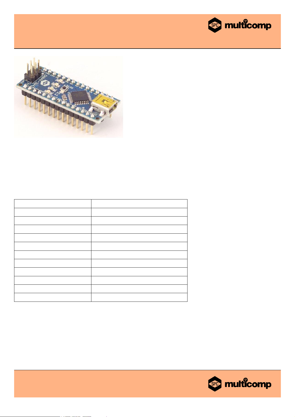
The MC-NANO is a small, complete, and breadboard-friendly board based on the ATmega328. It has more or less the same
functionality of the MC-NOVE, but in a different package. It lacks only a DC power jack, and works with a Mini-B USB cable
instead of a standard one.
Microcontroller ATmega328
Operating Voltage (logic level) 5V
Input Voltage (recommended) 7 to 12V
Input Voltage (limits) 6 to 20V
Digital I/O Pins 14 (of which 6 provide PWM output)
Analog Input Pins 8
DC Current per I/O Pin 40mA
Flash Memory 32KB of which 2KB used by bootloader
SRAM 2KB
EEPROM 1KB
Clock Speed 16MHz
Dimensions 0.73 inches x 1.70 inches
Summary
Power
The MC-NANO can be powered via the Mini-B USB connection, 6 to 20V unregulated external power supply (pin 30), or 5V
regulated external power supply (pin 27). The power source is automatically selected to the highest voltage source.
The FTDI FT232RL chip on the Nano is only powered if the board is being powered over USB. As a result, when running on
external (non-USB) power, the 3.3V output (which is supplied by the FTDI chip) is not available and the RX and TX LEDs will flicker
if digital pins 0 or 1 are high.
Page 2
MC-NANO
Arduino™ Nano Compatible Development Board
Page <2> 28/05/10 V1.1
http://www.farnell.com
http://www.newark.com
http://www.cpc.co.uk
Memory
The ATmega328 has 32KB (with 2KB used for the bootloader). The ATmega328 has 2KB of SRAM and 1KB of EEPROM. (which
can be read and written with the EEPROM library).
Input and Output
Each of the 14 digital pins on the Nano can be used as an input or output, using pinMode(), digitalWrite(), and digitalRead()
functions. They operate at 5 volts. Each pin can provide or receive a maximum of 40mA and has an internal pull-up resistor
(disconnected by default) of 20 to 50k ohms. In addition, some pins have specialized functions:
• Serial: 0 (RX) and 1 (TX). Used to receive (RX) and transmit (TX) TTL serial data. These pins are connected to the
corresponding pins of the FTDI USB-to-TTL Serial chip.
• External Interrupts: 2 and 3. These pins can be configured to trigger an interrupt on a low value, a rising or falling edge, or
a change in value. See the attachInterrupt() function for details.
• PWM: 3, 5, 6, 9, 10, and 11. Provide 8-bit PWM output with the analogWrite() function.
• SPI: 10 (SS), 11 (MOSI), 12 (MISO), 13 (SCK). These pins support SPI communication, which, although provided by the
underlying hardware, is not currently included in the Arduino™ language.
• LED: 13. There is a built-in LED connected to digital pin 13. When the pin is HIGH value, the LED is on, when the
pin is low, it's off.
The Nano has 8 analog inputs, each of which provide 10 bits of resolution (i.e. 1024 different values). By default they measure from
ground to 5 volts, though is it possible to change the upper end of their range using the analogReference() function. Additionally,
some pins have specialized functionality:
• I
2
C: 4 (SDA) and 5 (SCL). Support I2C (TWI) communication using the Wire library (documentation on the Wiring website).
There are a couple of other pins on the board:
• AREF. Reference voltage for the analog inputs. Used with analogReference().
• Reset. Bring this line LOW to reset the microcontroller. Typically used to add a reset button to shields which block the
one on the board.
Communication
The MC-NANO has a number of facilities for communicating with a computer, another board, or other microcontrollers. The
ATmega328 provide UART TTL (5V) serial communication, which is available on digital pins 0 (RX) and 1 (TX). An FTDI FT232RL
on the board channels this serial communication over USB and the FTDI drivers (included with the Arduino™ software) provide a
virtual com port to software on the computer. The Arduino™ software includes a serial monitor which allows simple textual data to
be sent to and from the Arduino™ board. The RX and TX LEDs on the board will flash when data is being transmitted via the FTDI
chip and USB connection to the computer (but not for serial communication on pins 0 and 1).
A SoftwareSerial library allows for serial communication on any of the Nano's digital pins.
The ATmega328 also support I2C (TWI) and SPI communication. The Arduino™ software includes a Wire library to simplify use of
the I2C bus; see the documentation for details. To use the SPI communication, please see the ATmega328 datasheet.
Page 3

MC-NANO
Arduino™ Nano Compatible Development Board
Page <3> 28/05/10 V1.1
http://www.farnell.com
http://www.newark.com
http://www.cpc.co.uk
Programming
The MC-NANO can be programmed with the Arduino™ software (download). Select "Arduino™ Duemilanove or Nano w/
ATmega328" from the Tools > Board menu. For details, see the reference and tutorials.
The ATmega328 on the MC-NANO comes pre-burned with a bootloader that allows you to upload new code to it without the use of
an external hardware programmer. It communicates using the original STK500 protocol (reference, C header files).
You can also bypass the bootloader and program the microcontroller through the ICSP (In-Circuit Serial Programming) header; see
these instructions for details.
Automatic (Software) Reset
Rather than requiring a physical press of the reset button before an upload, the MC-NANO is designed in a way that allows it to be
reset by software running on a connected computer. One of the hardware flow control lines (DTR) of the FT232RL is connected to
the reset line of the ATmega168 or ATmega328 via a 100 nanofarad capacitor. When this line is asserted (taken low), the reset line
drops long enough to reset the chip. The Arduino™ software uses this capability to allow you to upload code by simply pressing the
upload button in the Arduino™ environment. This means that the bootloader can have a shorter timeout, as the lowering of DTR can
be well-coordinated with the start of the upload.
This setup has other implications. When the Nano is connected to either a computer running Mac OS X or Linux, it resets each time
a connection is made to it from software (via USB). For the following half-second or so, the bootloader is running on the Nano.
While it is programmed to ignore malformed data (i.e. anything besides an upload of new code), it will intercept the first few bytes of
data sent to the board after a connection is opened. If a sketch running on the board receives one-time configuration or other data
when it first starts, make sure that the software with which it communicates waits a second after opening the connection and before
sending this data.
Schematic & Reference Design
EAGLE files: arduino-nano-reference-design.zip
Schematic: arduino-nano-schematic.pdf
Part Number Table
Description Part Number
BOARD, ATMEGA1280, MEGA-COMPATIBLE MC-MEGA
Disclaimer This data sheet and its contents (the "Information") belong to the Premier Farnell Group (the "Group") or are licensed to it. No licence is granted for the use of it other than for information purposes
in connection with the products to which it relates. No licence of any intellectual property rights is granted. The Information is subject to change without notice and replaces all data sheets previously supplied.
The Information supplied is believed to be accurate but the Group assumes no responsibility for its accuracy or completeness, any error in or omission from it or for any use made of it. Users of this data
sheet should check for themselves the Information and the suitability of the products for their purpose and not make any assumptions based on information included or omitted. Liability for loss or damage
resulting from any reliance on the Information or use of it (including liability resulting from negligence or where the Group was aware of the possibility of such loss or damage arising) is excluded.
This will not operate to limit or restrict the Group's liability for death or personal injury resulting from its negligence. SPC Multicomp is the registered trademark of the Group. © Premier Farnell plc 2010.
 Loading...