

Page 1
MULTICOM 3G
INSTALLATION GUIDE
--
Updated 36 page edition
--
REVISED
MAY 2017
Page 2
Contacting us:
For help with your Multicom, please
contact Multicom Customer Service,
email: [email protected]
online: www.suretek.com.au
phone: 1300 65 44 33 ( +61 2 8787 9865)
Multicom ® is a registered trademark.
Copyright © 2017 Multicom Systems.
All rights reserved.
Contents
Introduction........................................................3
Connect the Multicom......................................4
Arm/Disarm for AlarmLINK................................9
Setup Multicom Smart Modem........................16
Install TechTools.................................................18
Program the Multicom......................................22
Warranty Statement..........................................29
Copyright Notice & Disclaimers......................33
Wiring Diagram.................................................35
Resources..........................................................36
Scan QR
codes
to access
tutorials
Page 3
3Introduction
Introduction
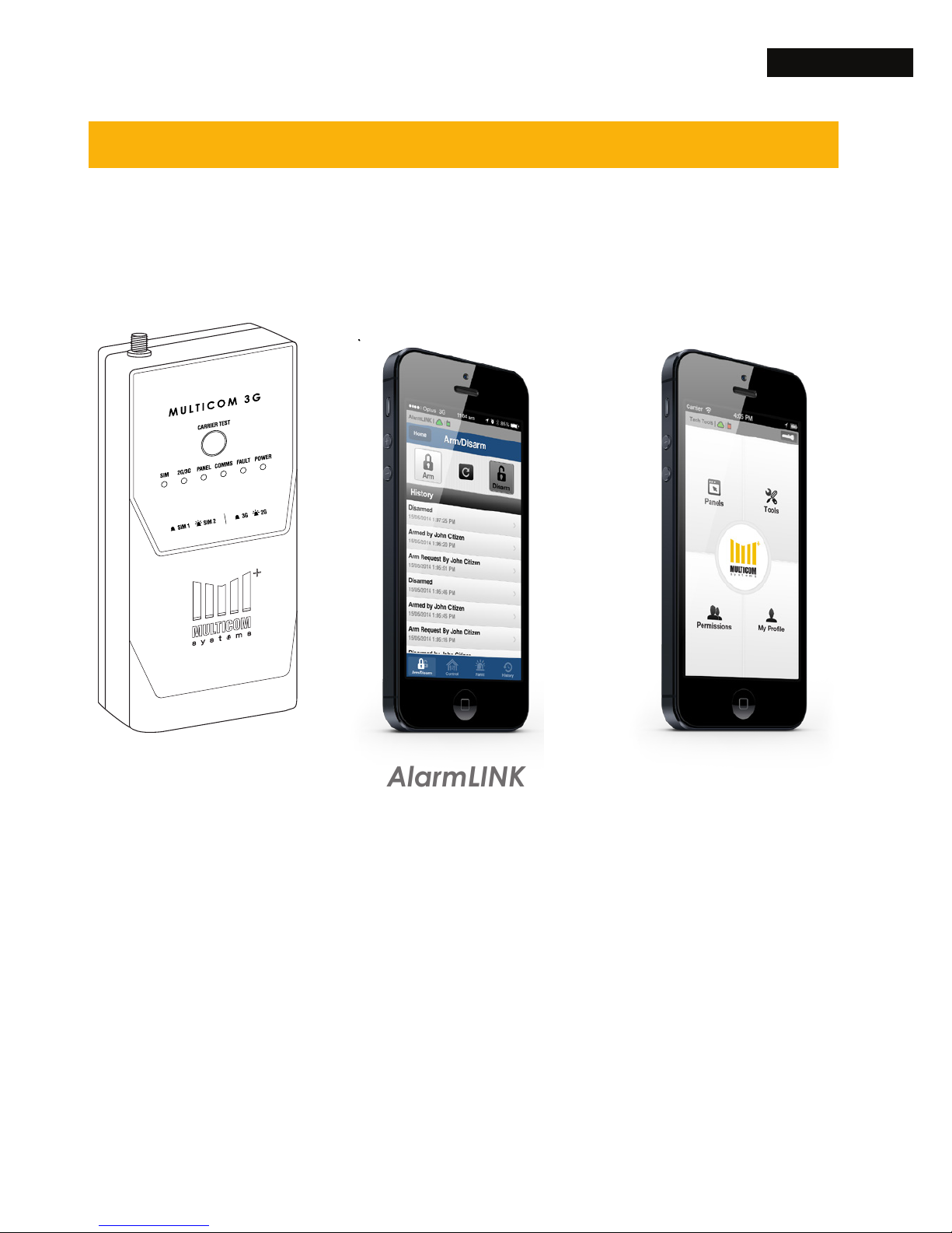
There are 19 steps in this Multicom 3G Installation Guide.
Please ensure you complete each step in order.
Multicom
(steps 1 - 4)
Connect the
Multicom Alarm
Communicator to
your alarm panel.
TechTools
(steps 11 - 19)
Install TechTools
to program the
Multicom. Add
relays and techs.
Use TechTools to
add customers
to AlarmLINK and
your logo.
AlarmLINK
(steps 5 - 10)
Setup arm/disarm
to give customers
control of the
Multicom via the
AlarmLINK app.
Test signal strength
and setup
remote modem.
Page 4
4 Connect the Multicom
Connect the Multicom
An overview of the basic hardware installation steps. The
full MC3G install manual also available, bit.ly/mc3gman.
1. Mount the Panel
Fix the included Velcro strip to the back of the
Multicom 3G (MC3G) to mount or place the box in
the desired location. Choose one of the following
mounting options:
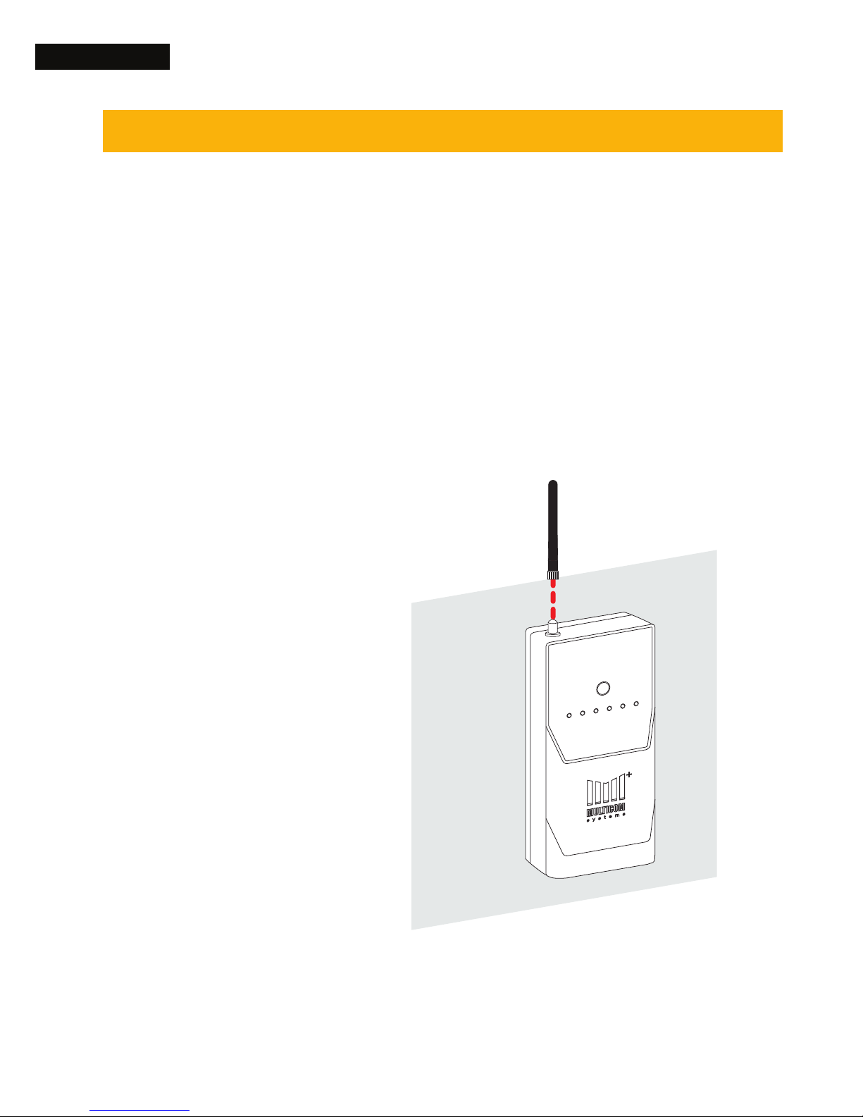
OPTION A
Mounting or
placement outside
the alarm panel
housing requires
the antenna to be
installed directly to
the Multicom 3G
(MC3G)
Outside of Alarm Panel Housing
Install antenna
Page 5
5Connect the Multicom
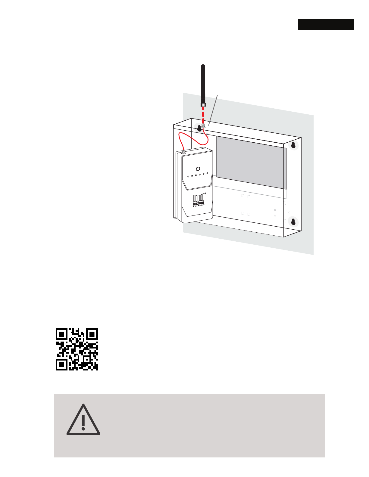
OPTION B
Mounting or
placement inside the
existing alarm panel
housing requires the
provided y lead to
be attached and the
included antenna to
be mounted to the
top of the panel
Drill Bit Size - 7mm
Note: If the MC3G is being installed in a poor
signal area, please consider using a highgain antenna available from your Multicom
supplier.
Inside of Alarm Panel Housing
Install y lead and antenna
bit.ly/multicom-install
Instructional video on how
to install the Multicom
Page 6
6 Connect the Multicom
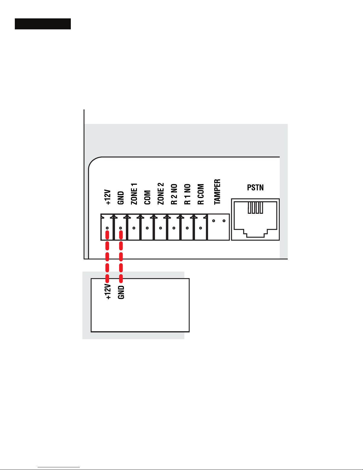
If there is no 12V auxiliary power output on the
alarm panel, which can provide a minimum of
300mA, connect to a Suretek MCPS12 power
supply (available separately) or a xed 12Vdc
power supply (>300mA).
Multicom
Alarm Panel
2. Connect to Power
Connect the 12V+ and GND pins on the MC3G to
the 12V auxiliary output on the alarm panel.
Page 7
7Connect the Multicom
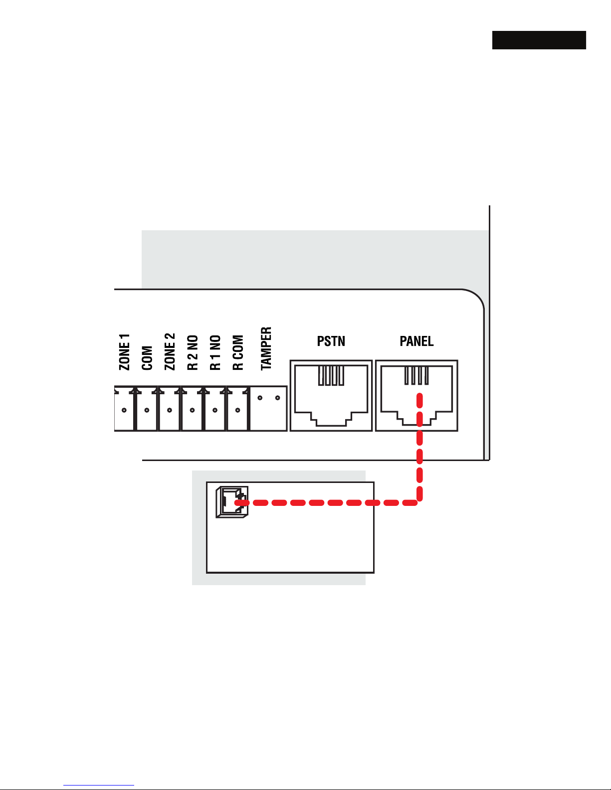
3. Connect to Panel
Connect the “PANEL” connection on the MC3G to
the “PSTN” connection on the alarm panel using a
4-wire RJ12 cable.
Multicom
Alarm Panel
Page 8
8 Connect the Multicom
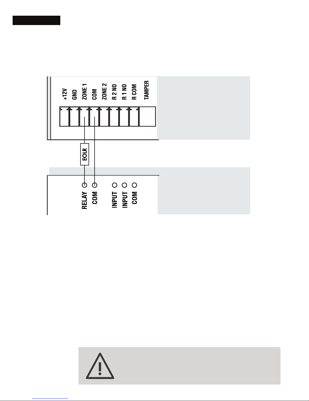
4. Interconnect Alarm Panel Relay Output
Relay/COM: To allow immediate notication of
communication failure to the Monitoring Centre,
program one of the alarm panel’s relay outputs to
trigger immediately on PSTN/COMM fail.
Connect the alarm panel’s relay output to one of
the MC3G’s zone inputs then ensure that the zone
is enabled. See Option 30.
3K3
Multicom
If not using Zone 2 make sure you seal
the zone with a 3K3 EOLR.
Alarm Panel
Page 9
9Arm/Disarm for AlarmLINK (Optional)
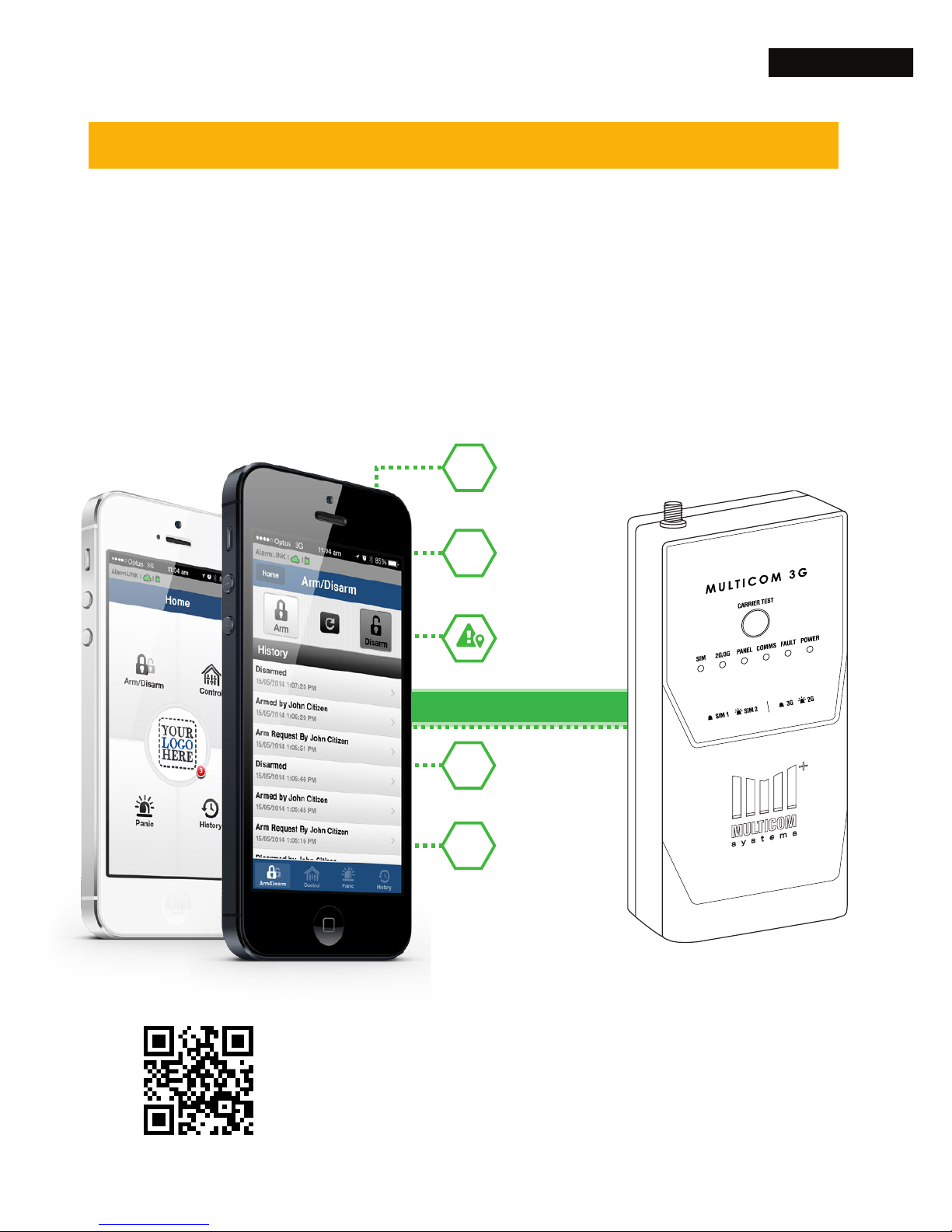
Provides your existing alarm
system with powerful new
features & superior security
Send panic alarms with your
location to your monitoring centre.
Remotely arm &
disarm your alarm system
Remotely control
lights, doors & gates
View alarm history
on your phone
Connect from anywhere in the world
Protect your family &
employees by downloading
on multiple devices.
AlarmLINK
3G/WiFi
Arm/Disarm for AlarmLINK (Optional)
Prepare your Multicom for arm/disarm and the AlarmLINK
app, (if you don’t want to setup arm/disarm, skip to Step 7).
AlarmLINK is a free-of-charge app that allows
customers to control the Multicom and attached
devices (shutters, gates, doors) via their smartphone.
bit.ly/alinkapp
AlarmLINK App Download
for Android and iPhone
Page 10
10 Arm/Disarm for AlarmLINK (Optional)
5. Arm/Disarm Connection
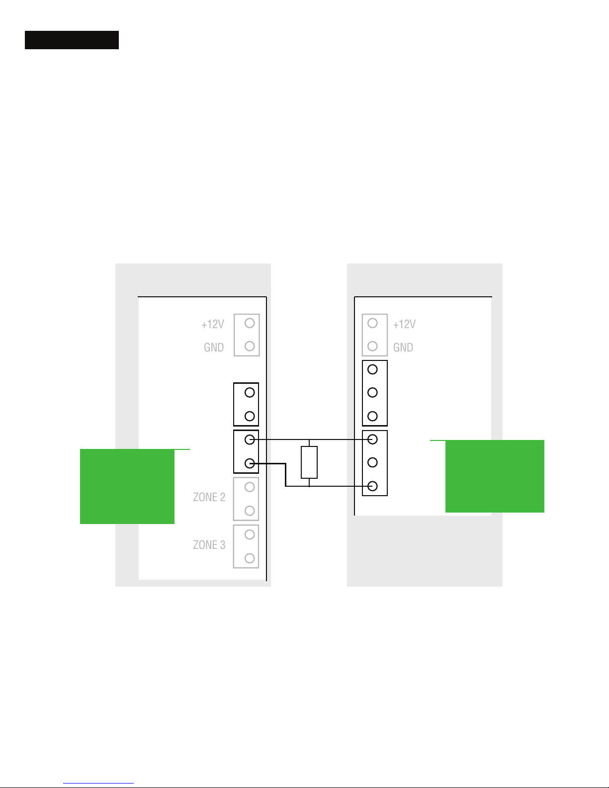
This step shows you how to wire the Multicom
and panel for arm/disarm and relay control.
Once setup the customer can control these
functions via the AlarmLINK App.
Connecting the second MC3G relay (R2
NO) is required to allow the end user to arm/
disarm the alarm panel via the AlarmLINK app.
Optionally it can be programmed from within
the TechTools app to control other devices such
as gates, doors, shutters etc.
ZONE 1
EOLR
Alarm Panel Multicom
RELAY 1
ZONE 2
ZONE 3
+12V
GND
+12V
GND
ZONE 1
COM
ZONE 2
R 2 NO
R 1 NO
R COM
PROGRAM AS
ARM/DISARM
OUTPUT
PROGRAM AS
ARM/DISARM
(KEY SWITCH)
Page 11

11Arm/Disarm for AlarmLINK (Optional)
6. Arm/Disarm Conguration:
Completion of steps 1-3 on the following page
is vital as it allows the AlarmLINK app to see the
open/close reports from the alarm panel to
complete the arm/disarm requests.
PLEASE READ BEFORE PROCEEDING
When a user requests arm/disarm, the
AlarmLINK app will not show the request
was successful until the open/close report is
received at the Monitoring Centre. These reports
are also used to sync the AlarmLINK app so the
user can verify if the panel is currently armed or
disarmed.
Alarm Panels do not generate the open/close
reports until AFTER the exit and entry delays so
the user will experience spinning wheel while
waiting for the open/close report to be sent, (if
the delay is too long). Or, if the reports are not
enabled the customer will experience a timeout
after 2 minutes and, the arm/disarm state will
not synchronise correctly on the AlarmLINK app.
Now please proceed to the next page which
provides the ‘Arm/Disarm Conguration’ steps.
Page 12

12 Arm/Disarm for AlarmLINK (Optional)
Arm/Disarm Conguration: steps required
1. Congure a zone on the alarm panel to
“Arm/Disarm input” (program as momentary
key switch).
2. Enable reporting of open/close reports. Do
this for both ‘stay’ and ‘away’ modes. This step
is important as the AlarmLINK app will not show
the request was successful until the open/close
report is received at the Monitoring Centre.
By default the Multicom is pre-congured to
pulse ‘Relay 2’ for 3 seconds on arm disarm
request.
3. Program the alarm panel entry and exit
delays to the ‘minimum time’ to speed up the
AlarmLINK arm/ disarm response time.
Please complete the congurations on
this step before proceeding to Step 7.
Page 13
13Arm/Disarm for AlarmLINK (Optional)
7. General Relay Control
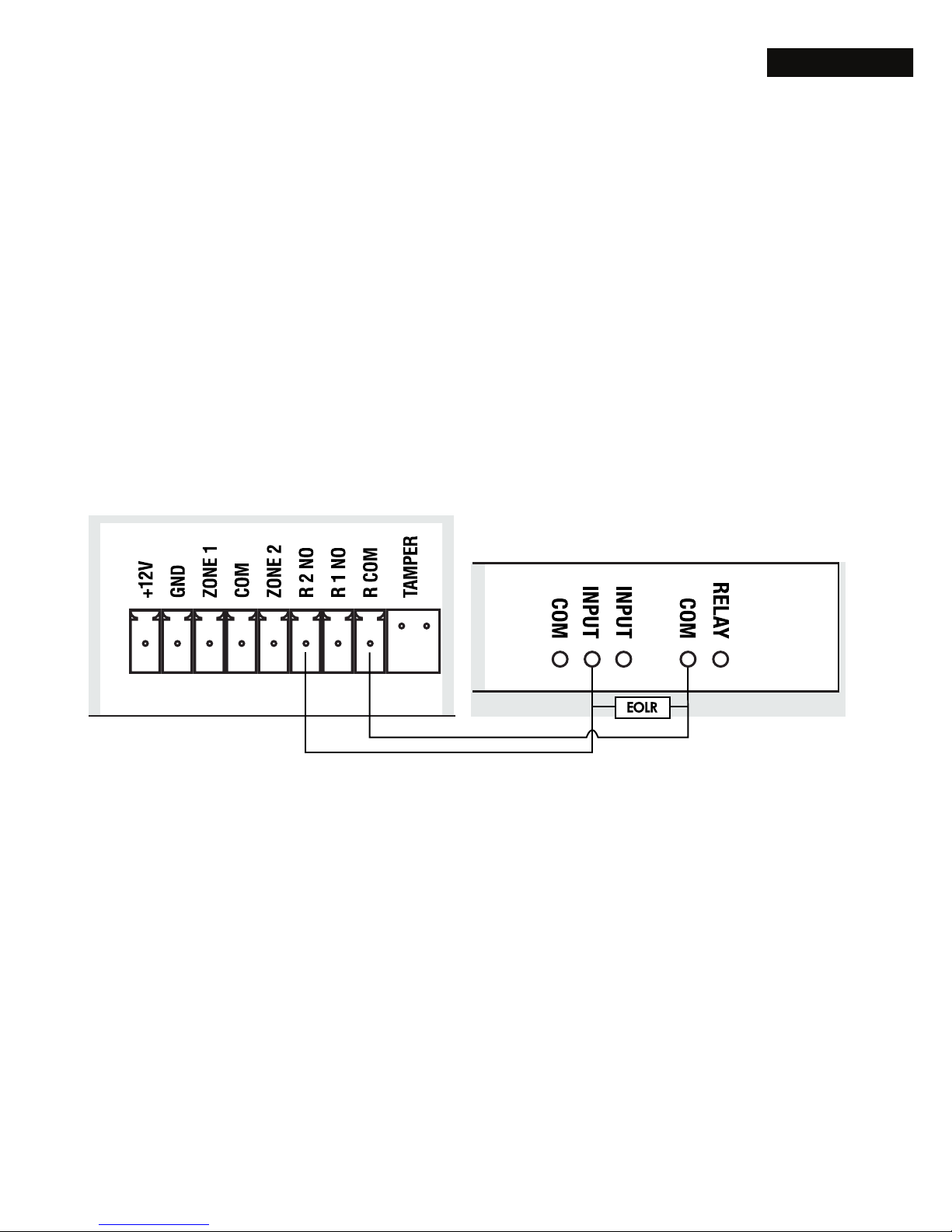
The AlarmLINK App allows your customers to
control electronic attached devices like gates &
doors from their smartphone.
You need to rst setup the device for general relay
control.
Wire the relay output (R1 NO or R2 NO) on the
Multicom device to your chosen device.
Please ensure you also wire a common ground.
R1 NO = RELAY 1, NORMALLY OPEN
R2 NO = RELAY 2, NORMALLY OPEN
COM = RELAY COMMON
Multicom
Page 14
14 Arm/Disarm for AlarmLINK (Optional)
8. Connect to the PSTN (Optional)
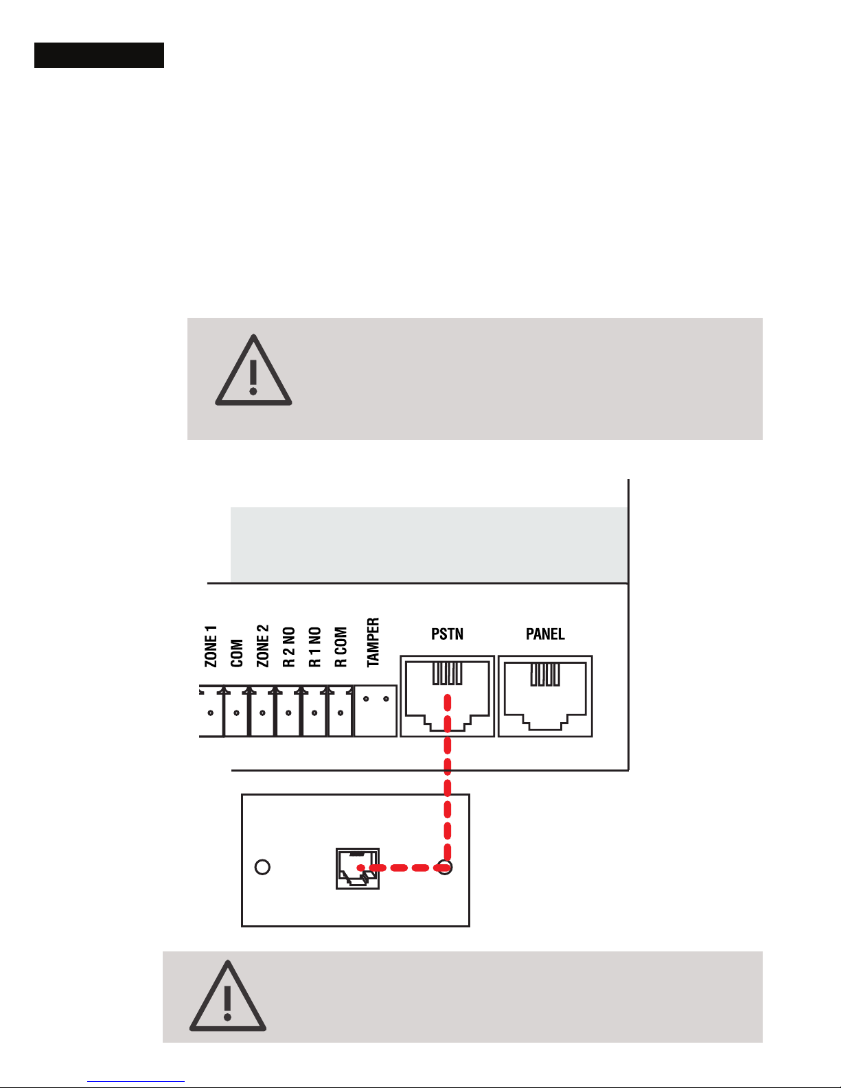
If PSTN will be used as a communicator path,
connect the PSTN socket to a standard PSTN
phone outline. Mode 3 is supported.
On MC3G Upload/Download hardware
PSTN is unavailable and this step should
skipped
If NOT using PSTN, PSTN fault detection must
be disabled (Option 39)
MC3G
Phone Line
Page 15
15Arm/Disarm for AlarmLINK (Optional)
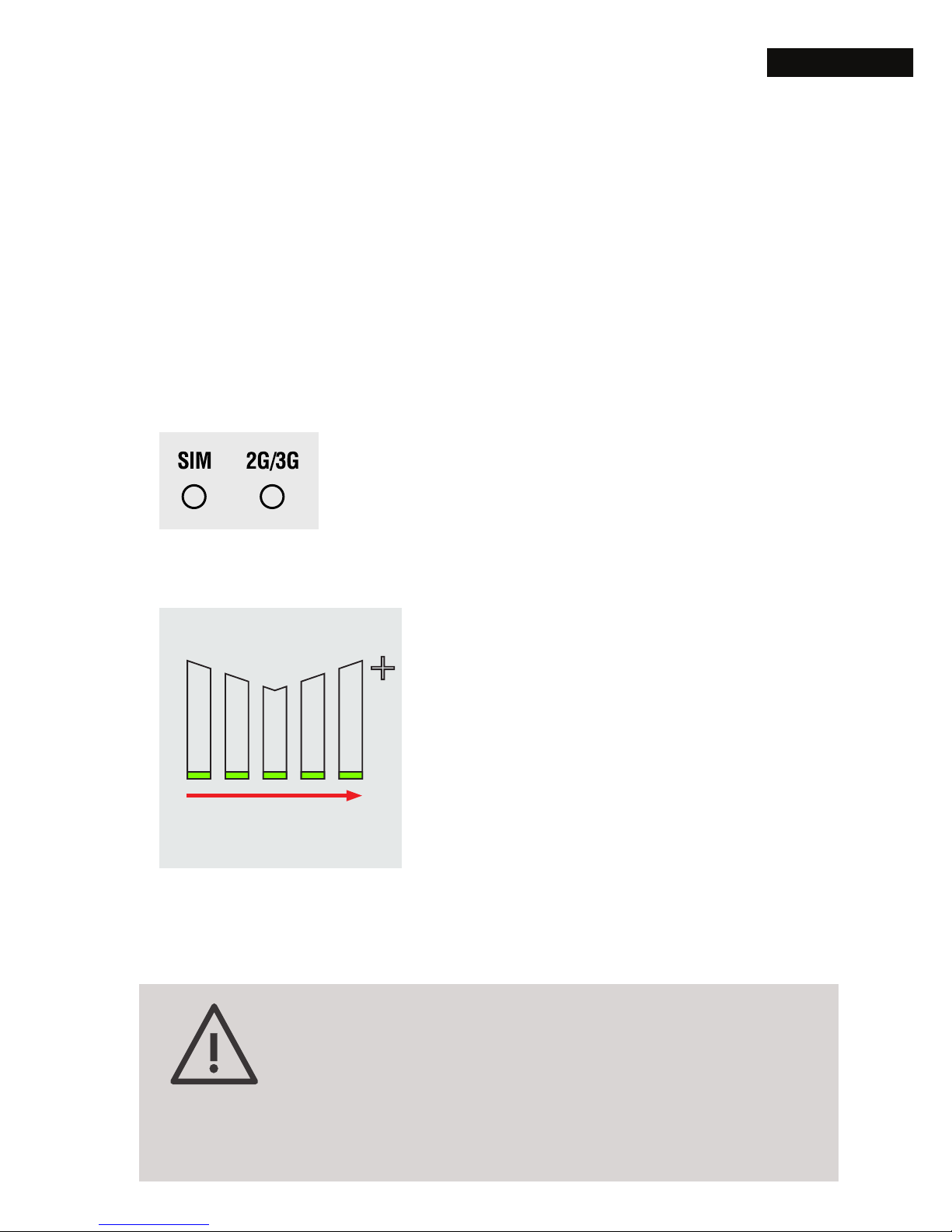
9. Test Signal Strength & Device
Power up the MC3G. The logo LED’s will act
as a signal strength indicator for the Active SIM
once connected. The SIM, 2G/3G, COMMS
and POWER LED’s should turn green once
connected.
SIM LED: Solid = Using SIM1
Flashing = Using SIM2
2G/3G LED: Solid = 3G Network
Flashing = 2G Network
To check the signal strength
on the Inactive SIM you can
press the ‘Carrier Test’ button
to switch SIM or log into it via
the TechTools app and visit
the ‘Survey’ tab.
If signal strength is less than 2 bars
(>95dB), you must relocate the device or
install a high-gain antenna. If one of the
SIMs cannot meet signal requirements,
the SIM may be disabled
SIGNAL STRENGTH
INDICATOR (1 to 5)
Page 16

16 Setup Multicom Smart Modem (Optional)
Setup Multicom Smart Modem (Optional)
MSM creates an IP-based, virtual modem connection
between U/D software and an alarm panel at client sites,
If you wish to skip this step, proceed to the ‘TechTools’
section on page 18.
10. Multicom Smart Modem for remote access
This guide assumes that you already have your
manufacturer supplied U/D software installed for
remote access and programming.
It is important that the Alarm Panel is
programmed with no answering machine
defeat and the alarm panel is programmed
to answer rst call 3rd ring otherwise remote
access will not be possible once you have left
the site.
Make sure you test each site ensuring the panel
is programmed correctly so you won’t have
to physically return to site to allow remote U/D
software access.
Multicom Smart Modem is installed on a
Windows computer. You can download the
software installation .exe le from here,
bit.ly/MSMsetup.
Page 17
17Setup Multicom Smart Modem (Optional)
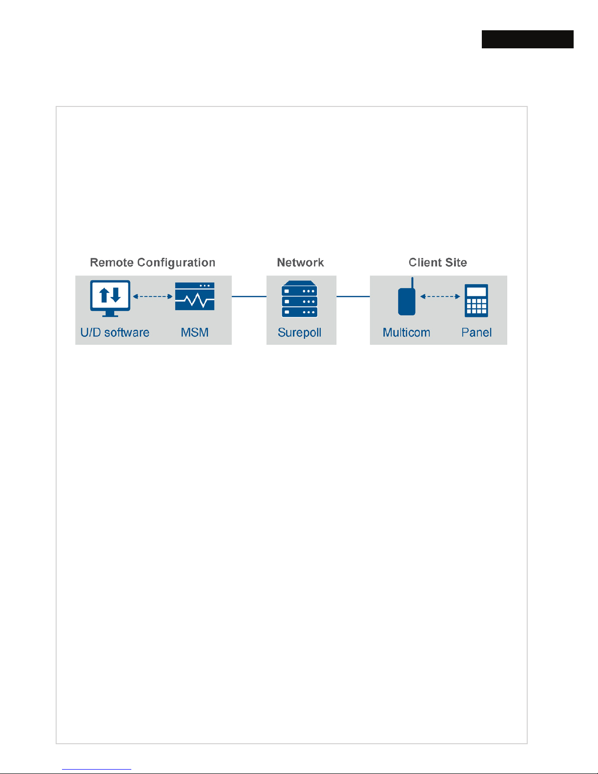
What is the Multicom Smart Modem (MSM)?
This is a time saving feature that gives you remote
conguration access to alarm panels while
attached to Upload/Download (U/D) enabled
Multicom Devices.
When an alarm panel has been upgraded
to a Multicom communicator, and PSTN is no
longer a reporting path, MSM allows traditional
U/D programming software to maintain
communication with the alarm system.
How does MSM work?
Once connected via the MSM, commands can be
issued from the U/D software as though connected
via a traditional PSTN path. When a connection is
detected on the virtual COM port, MSM will create
a tunnel to the alarm panel via the Surepoll Servers
and Multicom Device.
Page 18

18 Install TechTools
Install TechTools
To complete this next section you will need to install the
TechTools app onto your smartphone.
TechTools features:
• Centrally manage & congure Multicom devices
• Administer any number of eld technicians
• View all activity - alarms, polls and poll fails
• Complete library of alarm panel manuals built-in
To get basic activation, without TechTools,
call the Activation Centre on 1300 603 704
bit.ly/tt-tutorial
TechTools
video
tutorial
Page 19
19Install TechTools
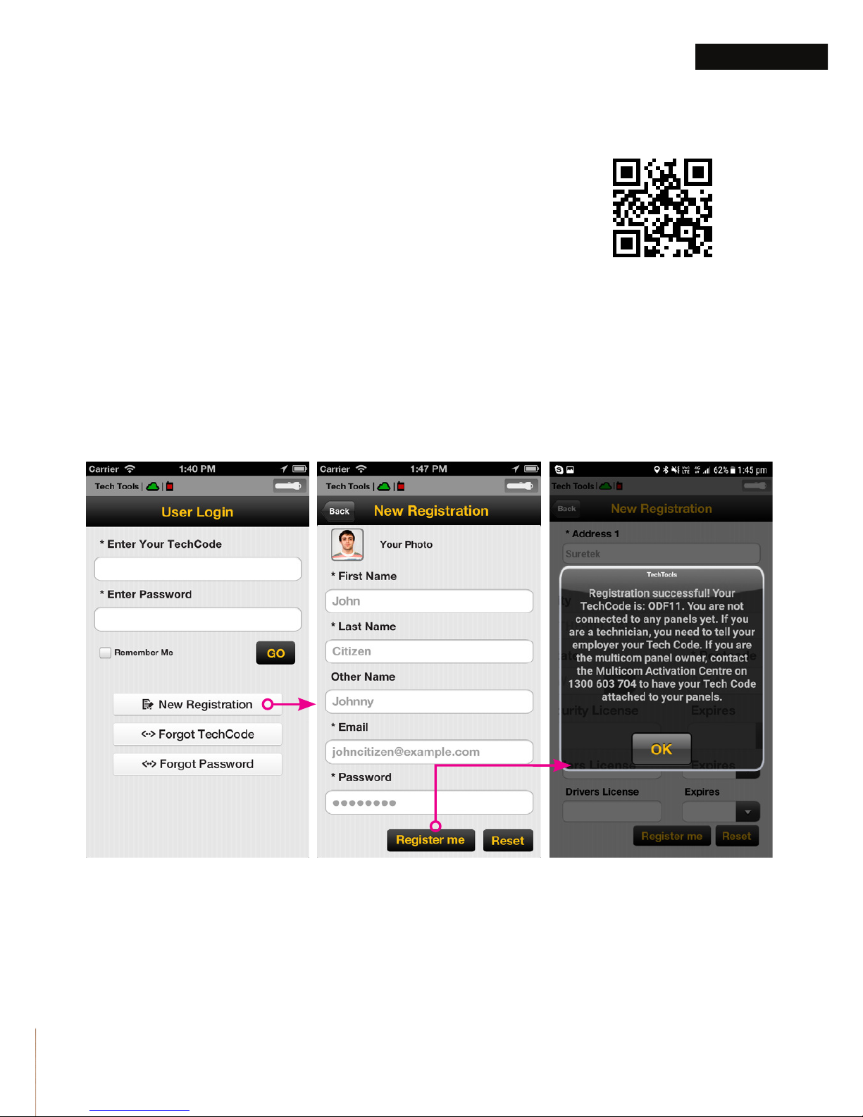
11. Download TechTools App
Use the QR code provided, or this
download link
---
> bit.ly/multicom
12. Register for a TechCode
Open TechTools. Tap New Registrations, ll in
your details. Now tap Register Me, you are then
given your TechCode.
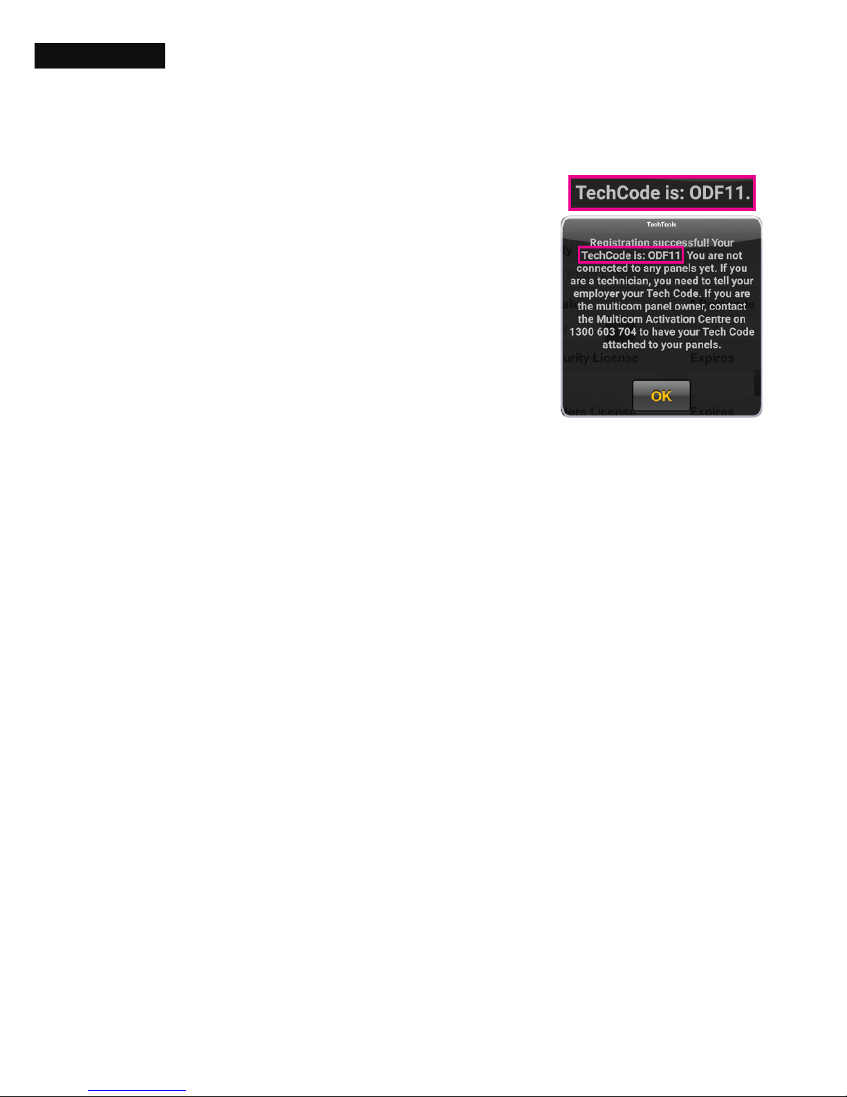
Take note of the TechCode provided, (the code
will also be emailed to you.)
Tap ‘New Registrations”, ll in details, and tap ‘Register me’
bit.ly/multicom
Page 20
20 Install TechTools
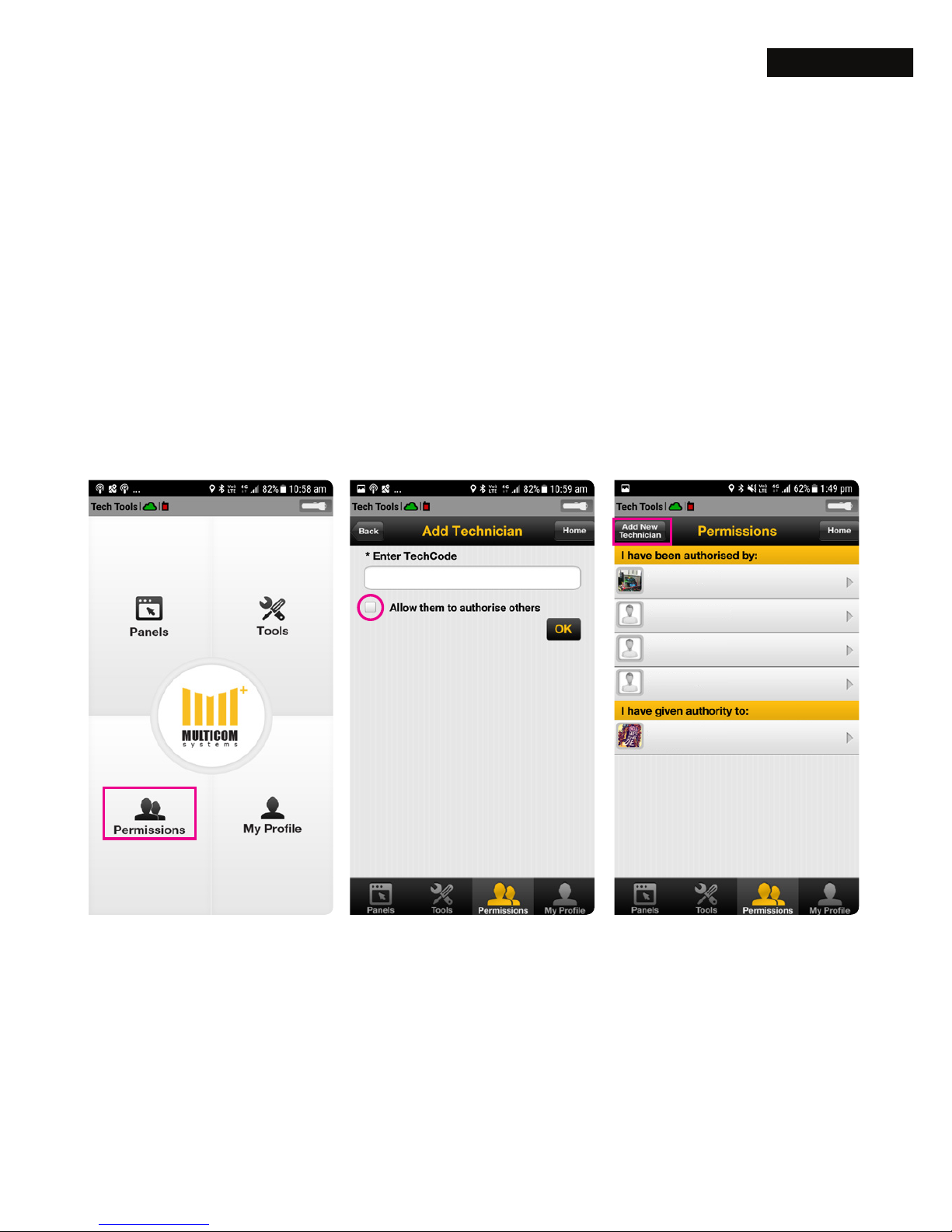
13. Authorise the TechCode
Technicians:
If you are installing the
Multicom on behalf of a
Bureau or Monitoring Centre,
you will need to forward the
TechCode to that company
who will then authorise your
TechCode allowing you to
access the Multicom.
Bureau/Monitoring Centre:
Initial conguration must be completed by
calling 1300 603 704 to tie a master TechCode
to your Multicom account. This only has to be
done once.
With the master TechCode you can then
control who has access to your Multicoms and
authorise other techs to access your Bureau/
Monitoring Centre Multicom TechCodes.
If you are a Bureau/Monitoring Centre please
complete the 3 steps on the opposite page.
Page 21
21Install TechTools
Steve Jones
COL
923
LJG
612
WDF
187
VSQ
405
FCD
840
David Smith
Greg Harris
Max Jarvis
Gary Stevens
Tick ‘Allow’ if you
want to allow this
technician to
authorise other
Multicom techs.
These 3 steps are for the Bureaus/Monitoring Centres:
1. Tap ‘Permissions’ 2. Enter ‘TechCode’ 3. Add Technician
Page 22
22 Program the Multicom
Program the Multicom
Once your TechCode has been authorised you can then
log on to the Multicom via TechTools.
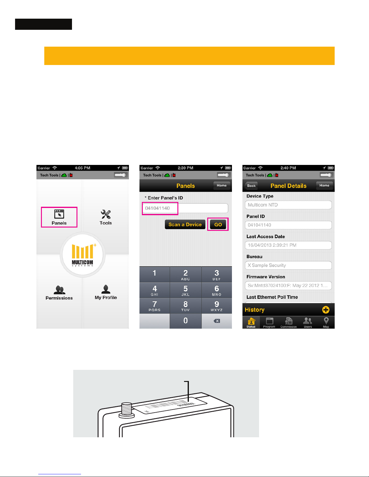
14. Log On
Launch TechTools on your smartphone to access
the Multicom. Proceed as follows:
1. Tap on ‘Panels’ 2. Enter the ‘Panel’s ID’ and tap Go
The Panel ID is found on the Multicom and outer packaging
Panel ID (0650XXXXX)
Page 23
23Program the Multicom
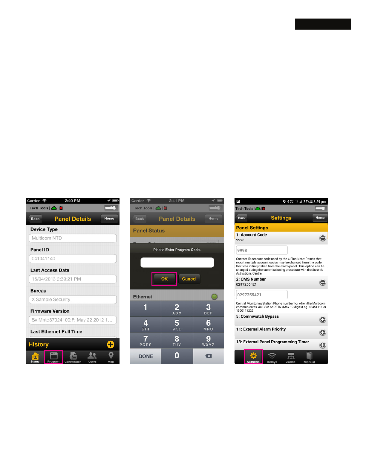
15. Accessing Program Menus
Tap on “Program” down the bottom, enter the
default code “1345” to enter programming
screen.
Tap on the “Settings” icon down the bottom,
and congure the Account Code and CMS
Number.
1. Tap on ‘Program’ 2. Enter ‘1345’, and
tap ‘OK’
3. Change settings
1345
Page 24
24 Program the Multicom
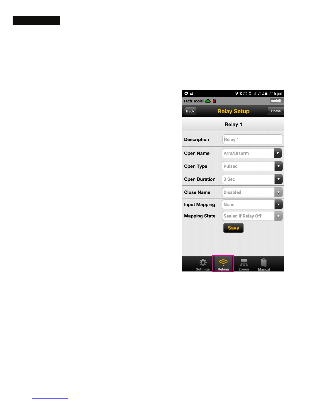
16. Customizing Relay conguration (Optional)
For controlling gates, doors shutters etc.
Description: Display
name for TechTools and
AlarmLINK
Open Name: Display
name when the Relay is
active (relay is ON)
Open Type: “Latched” for
a relay which will toggle
from one state to another
and “Pulsed” for a relay
which will activate for the
programmed time when
activated
Open Duration:
Only available when the Open Type is set to
Pulsed, this is the time in seconds the relay
will be activated when set from TechTools or
AlarmLINK.
Closed Name: Display name when the relay is
inactive (relay is OFF).
Page 25
25Program the Multicom
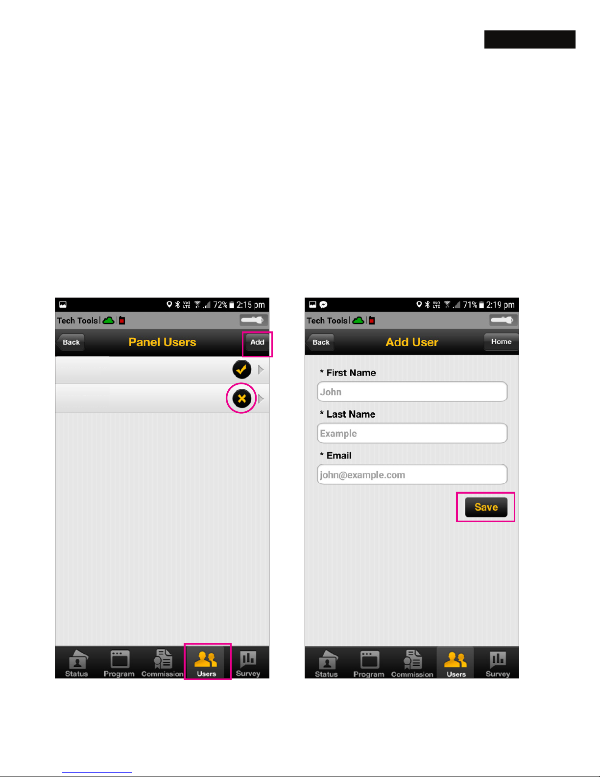
17. Add customer to AlarmLINK
AlarmLINK gives customer’s smartphone access
to arm/disarm, outputs, personal panic or history
viewing on their smartphone.
To provide your customers with AlarmLINK access,
complete the following 3 steps within TechTools:
Steve Jones
User ID: 546
Greg Harris
User ID: 774
1. Tap on ‘Users’, then tap
‘Add’
2. Enter customer details,
tap ‘Save’ - go to step 3...
Tap to toggle ON/OFF
user authorisation for
AlarmLINK access
Page 26
26 Program the Multicom
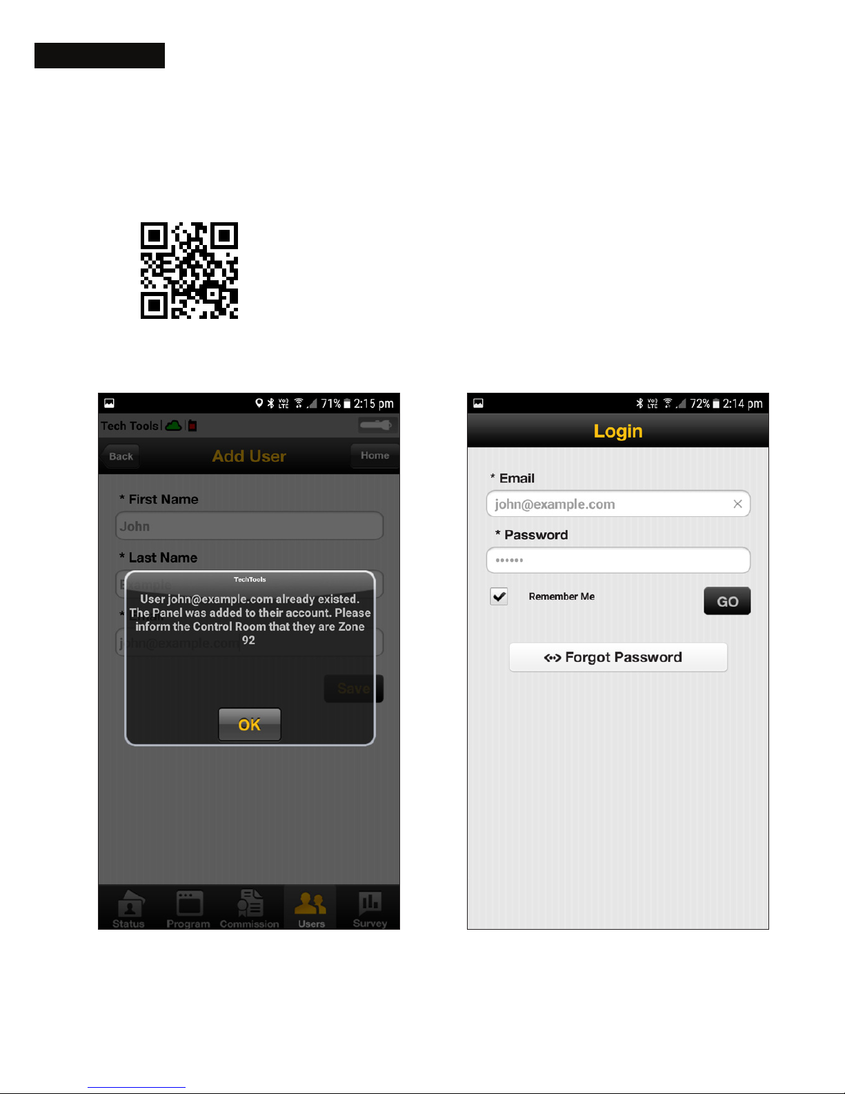
3. Tap ‘OK’. Customer will
now receive an AlarmLINK
download link and
password via email
>> Customer clicks
emailed link, then
downloads and opens
AlarmLINK and logs in
AlarmLINK free app download
bit.ly/alinkapp
Page 27
27Program the Multicom
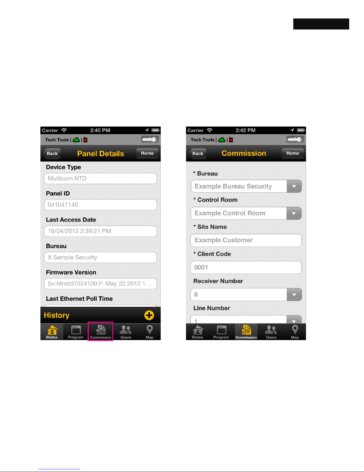
18. Commissioning
This step allows poll fail monitoring and alarm
delivery to your Monitoring Centre.
Enter the ‘Bureau’, ‘Monitoring station’ and
other required reporting details for the device
and press the ‘Activate’ button. Upon successful
commissioning you will receive this conrmation,
‘Panel has been activated successfully’.
1. Tap on ‘Commission’ 2. Enter the reporting details
Page 28
28 Program the Multicom
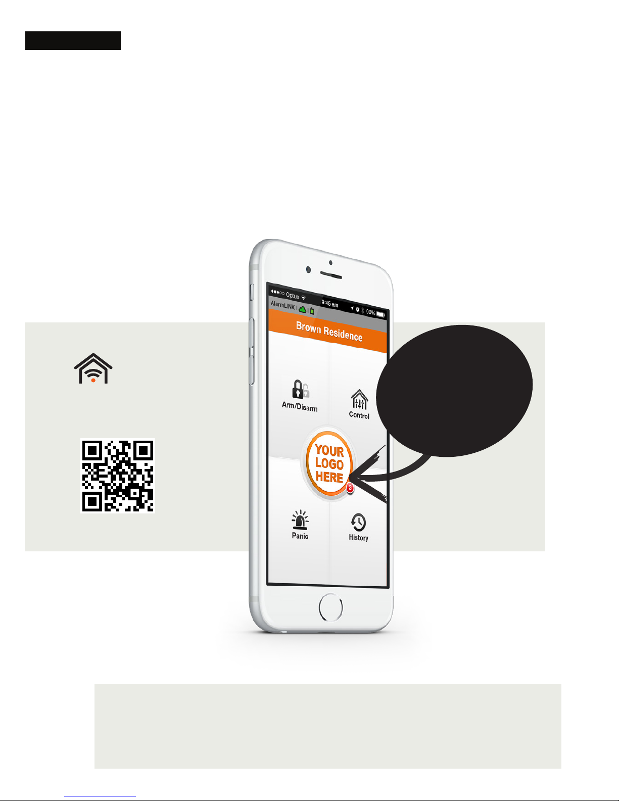
19. Add your logo to AlarmLINK (optional)
Send us your company logo and choice of colour
scheme and your branding will then be applied in
AlarmLINK for all of your Multicom installations.
AlarmLINK helps your customers and promotes
your business - www.suretek.com.au/AlarmLINK
Your logo
and colours
applied to
every panel
you install !
End User App
AlarmLINK
bit.ly/alinkapp
Page 29

29Limited Warranty Statement
Limited Warranty Statement
Multicom Systems (henceforth known as Multicom) warrants its products to
be free from defects in material and workmanship, under normal use, for
a period of twelve (12) months, or twenty four (24) months if the Multicom
product is installed by a ‘Certied Multicom Installer’, from the date of
purchase. If the warranted products are returned to Multicom during
this period of coverage, Multicom will repair or replace (at its discretion)
without charge, those items found to be defective. Any replacement or
repaired parts are warranted for the remainder of the original warranty or
ninety (90) days, whichever is longer. The original purchaser must promptly
notify their Multicom distributor, in writing during the warranty period, that
there is a defect in material or workmanship. All Multicom distributors and
dealers have a warranty program and you are expected to return your
product with proof of purchase in accordance with such a program. Prior
authorisation is required before returning the product, as Multicom will not
accept any shipment for which prior authorisation was not rst obtained.
Multicom will, at its option, repair or replace without charge, those
authorised returned items it nds defective.
Please note that this warranty does not cover any software products,
which are licensed under terms of a separate software license agreement
included with the product purchased. This warranty only applies to
defects in parts relating to Multicom products identied with a Multicom
product label and shall not cover transformers, metal boxes, access
cards & tags, batteries, tamper kits, spare parts, cables & connectors,
temperature sensors, promotional items & displays or any freight, and
labour.
This warranty does not cover damage incurred in shipping or handling,
problems that result from external causes such as accident, abuse, and
misuse, or problems with electrical power failures, or other damage
caused by:
Page 30

30 Limited Warranty Statement
• peripherals or unauthorised alterations or modications;
• servicing not authorised by a Multicom Certied Professional;
• usage that is not in accordance with product instructions;
• using accessories, parts or components not supplied or
recommended by Multicom;
• failure to provide a suitable installation environment for the
products;
• failure to change passwords, settings and/or pin codes from
factory default and;
• improper maintenance or failure to perform regular preventative
maintenance
Multicom’s responsibility for defects in material is limited to repair and
replacement of the product. Multicom does not accept liability beyond
the remedies provided for in this limited warranty or for any special,
indirect, consequential or incidental damages, including without
limitation, any liability for third party claims against you for damages.
Multicom’s maximum liability will be no more than the amount paid for
the product that is the subject of the claim. The laws of some jurisdictions
do not allow the disclaimer of consequential damages. Under such
circumstances, the limitations and disclaimers herein shall be to the
greatest extent permitted by law.
This warranty contains the entire warranty and shall be in lieu of any
and all other warranties, whether express or implied, including without
limitation, implied warranties and conditions of merchantability and
tness for a particular purpose, statutory or otherwise. This disclaimer of
warranties and limited warranty is governed by the laws of the New South
Wales, Australia.
Multicom will not be responsible for any custom fees, or taxes that may be
due. For those jurisdictions where the legal minimum warranty exceeds
the Multicom warranty period, this warranty will be equally extended to
meet such legal minimum requirement.
Page 31

31Limited Warranty Statement
Multicom does not install or connect the products, which may be used in
conjunction with other products not manufactured by Multicom; therefore
Multicom cannot guarantee or warrant the performance of the security
system. Multicom will not be responsible for circumstances resulting
from the product’s inability to operate. Your security system should be
considered as one of many tools available to reduce risk and/or damage
caused by burglary, re or other emergencies. Other tools include, but
are not limited to, access controls, lock products, insurance coverage, re
prevention, re extinguishing devices and sprinkler systems. We strongly
recommend that your security alarm system be tested and maintained on
a regular basis, and that you stay aware of new and improved Multicom
products and developments.
BEWARE: Dealers, installers and/or others selling, distributing or advertising
Multicom product(s) are not authorised to modify this warranty or make
any additional warranties that are binding on Multicom or distributors and
its afliates without the written approval from Multicom.
Multicom may change the terms of its limited warranty, without notice, at
its discretion.
WARNING: Due to limitations of Alarm Systems, Multicom cannot
guarantee the performance of the security system and shall not be
responsible for circumstances resulting from the product’s inability to
operate. It must be understood that while your Multicom product is highly
advanced and secure, it only forms part of your total security installation
and it does not offer any guaranteed protection against burglary, re
or other emergency. This is due to a number of reasons, including, but
not limited to, inadequate or improper installation/positioning, sensor
limitations, battery performance, wireless signal interruption, inadequate
maintenance, or the potential for communication mediums to be
compromised or circumvented. As a result, Multicom does not represent
that the alarm system will prevent personal injury or property damage, or
in all cases provide adequate warning or protection. Your security system
Page 32

32 Limited Warranty Statement
should therefore be considered as one of many tools available to reduce
risk and/or damage of burglary, re or other emergencies; such other tools
include, but are not limited to insurance coverage, re prevention and
extinguisher devices, and sprinkler systems. We also strongly recommend
you to regularly maintain your security systems and stay aware of new and
improved Multicom products and developments. For those customers
who are using a security system connected to a non-traditional telephone
system, such as “Voice Over Internet Protocol” (VoIP) that converts the
voice signal from your telephone to a digital signal travelling over the
Internet, you should be aware that your alarm system may not function as
effectively as with traditional telephone systems. For example, if your VoIP
equipment has no battery back-up, during a power failure your system’s
ability to transmit signals to the central station may be compromised.
Or, if your VoIP connection becomes disabled, your telephone line
monitoring feature may also be compromised. Other concerns would
include, without limitation, Internet connection failures, which may be
more frequent than regular telephone line outages. We therefore strongly
recommend that you discuss these and other limitations involved with
operating an alarm system on a VoIP or other non-traditional telephone
system with your installation company. They should be able to offer or
recommend measures to reduce the risks involved and give you a better
understanding. The Multicom range of communication products are
designed to detect all communication failures within the network and
are designed to work effectively around traditional telephone systems
in addition to Non-Traditional Telephony such as VoIP, GPRS, 3G and
new communication mediums including the (NBN) National Broadband
Network.
Page 33

33Copyright Notice & Disclaimers
Copyright Notice & Disclaimers
Copyright © 2017 Multicom Systems Pty Ltd. All rights reserved
Multicom 3G Installation Guide - Revised May 2017
Maintenance Release V1.7
Please address your comments and suggestions to Multicom Systems on
1300 65 44 33.
Changes may be made periodically to the information in this publication.
The changes will be incorporated in new editions of the guide.
This guide and the software described in this document is furnished under
a license agreement, and may be used or copied only in accordance
with the terms thereof. It is against the law to copy the user guide and
software on any other medium, except as specically provided in the
license agreement. The licensee may make one copy of the software for
backup purposes.
No part of this publication may be reproduced, stored in a retrieval
system, or transmitted in any form or by any means, electronic,
mechanical, photocopied, recorded or otherwise, without the prior
written permission of Multicom Systems Pty Ltd.
The software license and limited warranty for the accompanying products
are set forth in the information packet supplied with the product, and are
incorporated herein by this reference. If you cannot locate the software
license, contact your Multicom Systems representative for a copy.
All product names mentioned in this manual are for identication
purposes only, and are either trademarks or registered trademarks of their
respective owners.
Page 34

34 Notes
Notes
Page 35
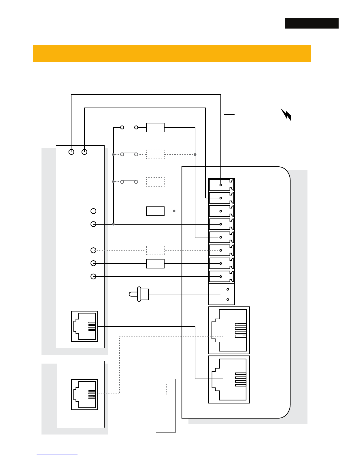
35Wiring Diagram
+12V
GND
ZONE 1
COM
ZONE 2
R 2 NO
R 1 NO
R COM
TAMPER
PSTN PANEL
RELAY
COM
+12V
GND
INPUT
INPUT
COM
TAMPER
PSTN
ZONE 1
3K3
EOLR
EOLR
ZONE 2
ZONE 4
ZONE 3
6K8
3K3
6K8
Alarm Panel Phone Line
Multicom 3G
PSTN (MODE3)
IMPORTANT!
Alarm Panel must be
able to supply >300mA
to MC3G. If not, use a
MCPS12 power supply
(available separately).
Optional
PSTN is unavailable on
MC3G Upload/
Download hardware
Wiring Diagram
Page 36
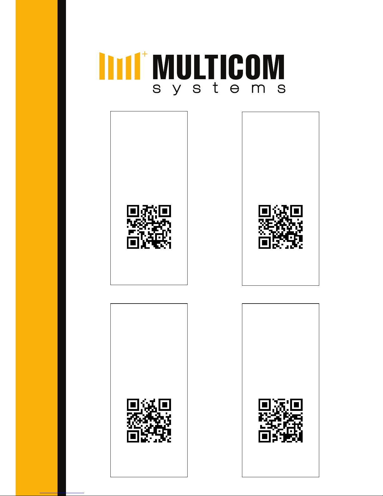
bit.ly/multicom
TechTools
Download
Download the
TechTools App for
smart phones.
bit.ly/alinkguide
AlarmLINK
Setup Guide
Setup the end
user app for your
customer.
bit.ly/mc3gman
Multicom
Full Manual
A complete
instructional
guide.
bit.ly/alinkapp
AlarmLINK
App Download
Available for
iPhone and
Android.
 Loading...