

Page 1
multichannel
systems
Wireless Headstages
Technical Specifications of Wireless Headstages
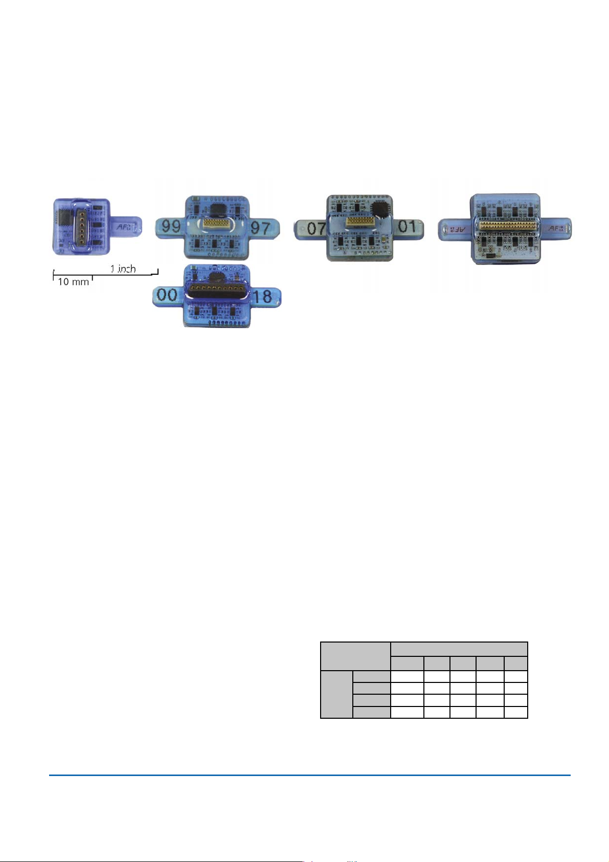
W4-Headstage W8-Headstage W16-Headstage W32-Headstage
Single row connector Omnetics or single row con. Omnetics connector Omnetics connector
*
Technical Specifications
Headstage
Number of channels 4, 8, 16 or 32
Dimensions (W x D x H) W4 13 x 13 x 5
(w/o antennae in mm) W8 16 x 16 x 5
W16 16 x 16 x 6.5
W32 16 x 16 x 7.5
Weight (w/o battery) W4 2.2 g
W8 2.9 g
W16 3.6 g
W32 3.7 g
Amplifier integrated in the Headstage
Bandwidth 1 Hz to 5 kHz (0.1 Hz on request)
Resolution 16 bit
Sampling rate in kHz per channel
Sampling rate
(kHz/ch)
Type of
W4-HS 40 20 ---
W8-HS 40 40 20 --
head-
W16-HS 20 20 20 10 -
stage
W32-HS 10 10 10 10 5
Number of selected channels
2481632
Input voltage range + / - 12.4 mV
Distance for wireless link 5 m guaranteed
Multi Channel Systems
MCS GmbH
Aspenhaustrasse 21
72770 Reutlingen
Germany
Fon +49-7121-9 09 25Fax
+49-7121-9 09 25-11
info@multichannelsystems.com
www.multichannelsystems.com
0
© 2014 Multi Channel Systems MCS GmbH
Product information is subject to change
without notice.
Page 2
multichannel
systems
Wireless Headstages
Technical Specifications of Wireless Headstages
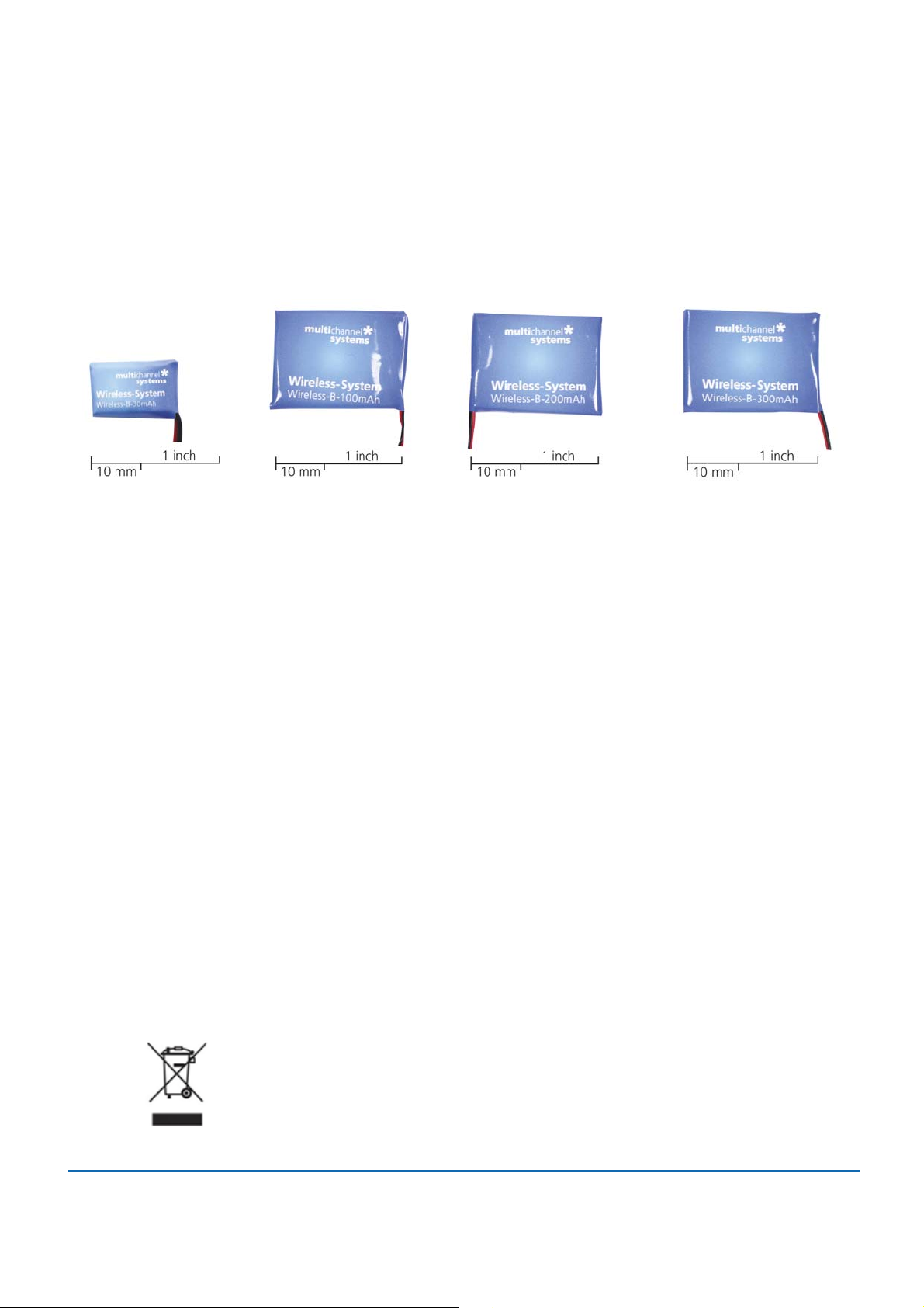
30 mAh Battery 100 mAh Battery 200 mAh Battery 300 mAh Battery
*
Technical Specifications
Batteries
Dimensions in mm Weight in g
Length Width Height Weight
30 mAh battery 17 11 3 1.5
100 mAh battery 26 19.5 2.3 3.1
200 mAh battery 26 20 4.5 4.6
300 mAh battery 27.5 19.5 5 6.8
Recording Time of batteries in hours at maximal sampling rate on all available channels
W4-HS W8-HS W16-HS W32-HS
30 mAh battery 1.0 0.6 0.5 0.4
100 mAh battery 3.2 2 1.7 1.3
200 mAh battery 6.4 4 3.4 2.6
300 mAh battery 11.2 6.8 5.9 3.9
Batteries do not belong in normal household waste and, thus,
must always disposed of within the framework of existing legislation.
Multi Channel Systems
MCS GmbH
Aspenhaustrasse 21
72770 Reutlingen
Germany
Fon +49-7121-9 09 25Fax
+49-7121-9 09 25-11
info@multichannelsystems.com
www.multichannelsystems.com
0
© 2014 Multi Channel Systems MCS GmbH
Product information is subject to change
without notice.
Page 3
multichannel
systems
W4-Headstage
Pin Layout of the 4-Channel Headstage for the Wireless Recording System
*
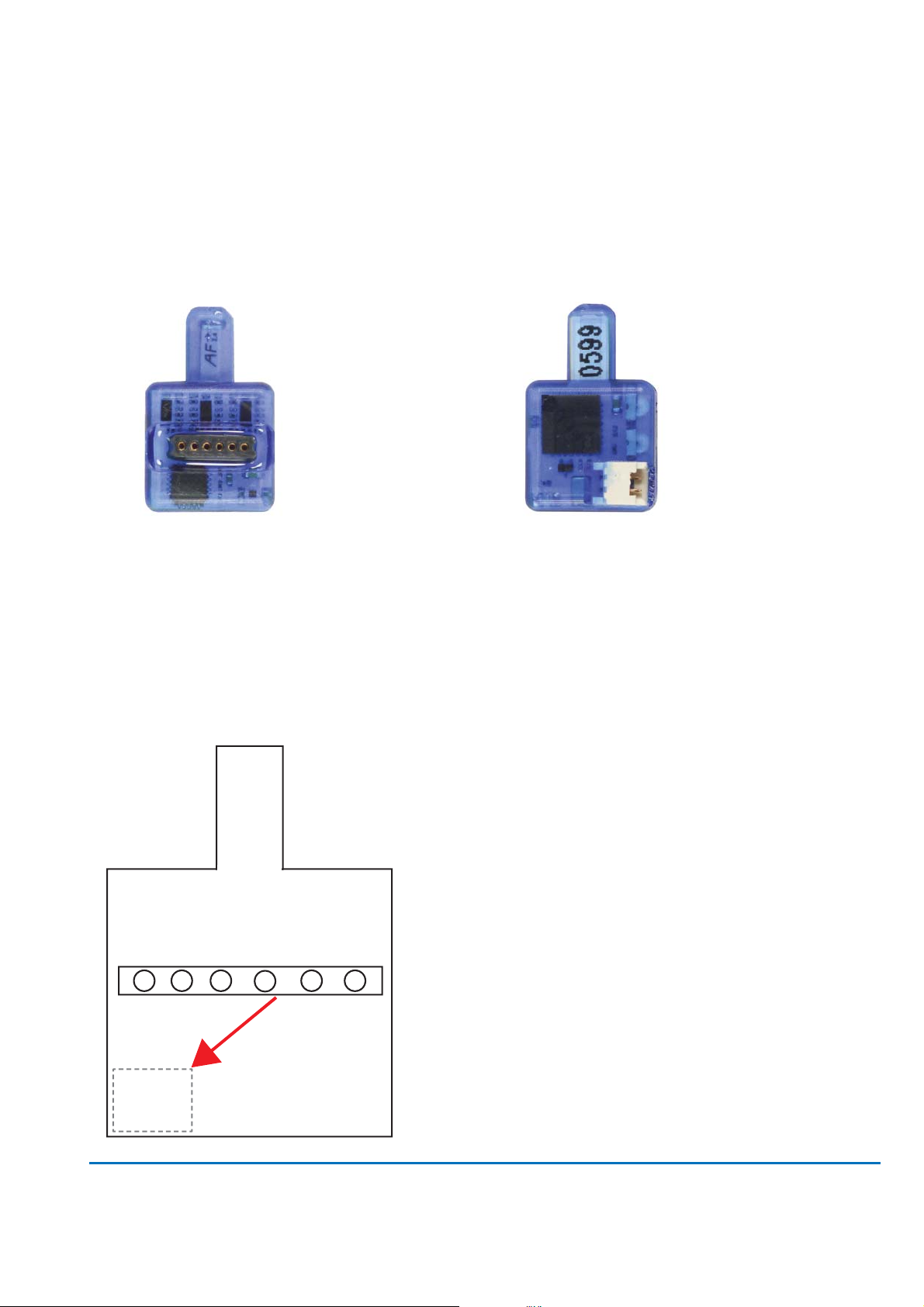
W4-Headstage bottom side:
Connector for the electrode probe
or for the ME/W-Signal generator
W4-Headstage with single row socket
Diagram of the bottom side with pin layout:
GND REF 4 3 2 1
W4-Headstage top side:
The white connector is for the storage battery.
Please use this connector for orientation of the
headstage.
Please orientate the headstage
as shown in the diagram.
Pin Layout of the single row precession socket
(1.27 mm, round pin).
Channel 1
Channel 2
Channel 3
Channel 4
REF (Reference)
GND (Ground)
Storage battery connector
on the opposite side
for orientation.
Multi Channel Systems
MCS GmbH
Aspenhaustrasse 21
72770 Reutlingen
Germany
Fon +49-7121-9 09 25Fax
+49-7121-9 09 25-11
info@multichannelsystems.com
www.multichannelsystems.com
Connector for W4-Headstage
The connector mates with a standard
single row 1.27 mm pin connector such as:
preci-dip 850-10-006-10-001101
0
© 2014 Multi Channel Systems MCS GmbH
Product information is subject to change
without notice.
Page 4

multichannel
W4-Headstage
Technical Specifications
W4-Headstage
Number of channels 4
Dimensions (W x D x H) 13 x 13 x 5 mm
(w/o antennae)
Weight (w/o battery) 2.2 g
Amplifier integrated in the Headstage
Bandwidth 1 Hz to 5 kHz (0.1 Hz on request)
Resolution 16 bit
systems
*
Sampling rate
4 channels simultaneously 20 kHz
2 channels simultaneously 40 kHz
Input voltage range + / - 12.4 mV
Distance for wireless link 5 m guaranteed
Batteries
Dimensions in mm Weight in g
Length Width Height Weight
30 mAh battery 17 11 3 1.5
100 mAh battery 26 19.5 2.3 3.1
200 mAh battery 26 20 4.5 4.6
300 mAh battery 27.5 19.5 5 6.8
Recording Time of batteries in hours at maximal sampling rate on all four channels
W4-HS
30 mAh battery 1.0
100 mAh battery 3.2
200 mAh battery 6.4
300 mAh battery 11.2
Multi Channel Systems
MCS GmbH
Aspenhaustrasse 21
72770 Reutlingen
Germany
Fon +49-7121-9 09 25Fax
+49-7121-9 09 25-11
info@multichannelsystems.com
www.multichannelsystems.com
0
© 2014 Multi Channel Systems MCS GmbH
Product information is subject to change
without notice.
Page 5

multichannel
systems
W8-Headstage
Pin Layout of the 8-Channel Headstage for the Wireless Recording System
*
W8-Headstage bottom side:
Connector for the electrode probe
or the ME/W-Signal generator.
W8-Headstage with single row socket
Diagram of the bottom side with pin layout.
GND REF E1 E2 E3 E4 E5 E6 E7 E8
Storage battery connector
on the opposite side
for orientation.
W8-Headstage top side:
The white connector is for the storage battery.
Please use this connector for the orientation
of the headstage.
Please orientate the headstage
as shown on the diagram.
Connector for W8-Headstage
with single row socket
The connector mates with a standard
single row 1.27 mm pin connector such as:
preci-dip
850-10-010-10-001101
Pin Layout of the single row precession socket (1.27 mm, round pin).
Please orientate the headstage as shown on the diagram.
GND Ground
REF Reference
E1 Electrode 1 Channel 1
E2 Electrode 2 Channel 2
E3 Electrode 3 Channel 3
E4 Electrode 4 Channel 4
E5 Electrode 5 Channel 5
E6 Electrode 6 Channel 6
E7 Electrode 7 Channel 7
E8 Electrode 8 Channel 8
Multi Channel Systems
MCS GmbH
Aspenhaustrasse 21
72770 Reutlingen
Germany
Fon +49-7121-9 09 25Fax
info@multichannelsystems.com
www.multichannelsystems.com
MC_Rack
+49-7121-9 09 25-11
0
© 2014 Multi Channel Systems MCS GmbH
Product information is subject to change
without notice.
Page 6

multichannel
systems
W8-Headstage
Pin Layout of the 8-Channel Headstage for the Wireless Recording System
*
W8-Headstage bottom side:
Connector for the electrode probe
or the ME/W-Signal generator via
the adapter ADPT-Om-ME/W-SG.
W8-Headstage with Omnetics socket
Diagram of the bottom side with pin layout.
NC NC NC NC NC NC NC NC
REF
REF E1 E2 E3 E4 E5 E6 E7 E8 GND
Storage battery connector
on the opposite side
for orientation.
GND
W8-Headstage top side:
The white connector is for the storage battery.
Please use this connector for the orientation
of the headstage.
Please orientate the headstage
as shown on the diagram.
Connector for W8-Headstage
with Omnetics socket
The Omnetics connector mates
with standard pin connector such as:
Through-Hole:
A79038-001 (NPD-18-DD-GS)
Horizontal Surface Mount:
A79040-001 (NPD-18-AA-GS)
Vertical Surface Mount:
A79042-001 (NPD-18-VV-GS)
Cable (18.0" 34 AWG lead-wire):
A79044-001 (NPD-18-WD-18.0-C-GS)
Pin Layout of the Omnetics socket A79039-001.
Please orientate the headstage as shown on the diagram.
Guide post REF Reference
NC not connected E1 Electrode 1 Channel 1
NC not connected E2 Electrode 2 Channel 2
NC not connected E3 Electrode 3 Channel 3
NC not connected E4 Electrode 4 Channel 4
NC not connected E5 Electrode 5 Channel 5
NC not connected E6 Electrode 6 Channel 6
NC not connected E7 Electrode 7 Channel 7
NC not connected E8 Electrode 8 Channel 8
Guide post GND Ground
Multi Channel Systems
MCS GmbH
Aspenhaustrasse 21
72770 Reutlingen
Germany
Fon +49-7121-9 09 25Fax
+49-7121-9 09 25-11
info@multichannelsystems.com
www.multichannelsystems.com
0
© 2014 Multi Channel Systems MCS GmbH
Product information is subject to change
without notice.
MC_Rack
Page 7

multichannel
W8-Headstage
Technical Specifications
W8-Headstage (Omnetics or single row connector)
Number of channels 8
Dimensions (W x D x H) 16 x 16 x 5 mm
(w/o antennae)
Weight (w/o battery) 2.9 g
Amplifier integrated in the Headstage
Bandwidth 1 Hz to 5 kHz (0.1 Hz on request)
Resolution 16 bit
systems
*
Sampling rate
8 channels simultaneously 20 kHz
4 channels simultaneously 40 kHz
2 channels simultaneously 40 kHz
Input voltage range + / - 12.4 mV
Distance for wireless link 5 m guaranteed
Batteries
Dimensions in mm Weight in g
Length Width Height Weight
30 mAh battery 17 11 3 1.5
100 mAh battery 26 19.5 2.3 3.1
200 mAh battery 26 20 4.5 4.6
300 mAh battery 27.5 19.5 5 6.8
Recording Time of batteries in hours at maximal sampling rate on all eight channels
W8-HS
30 mAh battery 0.6
100 mAh battery 2
200 mAh battery 4
300 mAh battery 6.8
Multi Channel Systems
MCS GmbH
Aspenhaustrasse 21
72770 Reutlingen
Germany
Fon +49-7121-9 09 25Fax
+49-7121-9 09 25-11
info@multichannelsystems.com
www.multichannelsystems.com
0
© 2014 Multi Channel Systems MCS GmbH
Product information is subject to change
without notice.
Page 8

multichannel
systems
W16-Headstage
Pin Layout of the 16-Channel Headstage for the Wireless Recording System
*
W16-Headstage bottom side:
Connector for the electrode probe
or the ME/W-Signal generator.
W16-Headstage with Omnetics connector
A79039-001 (NSD-18-DD-GS)
Diagram of the bottom side with pin layout.
GND 1 3 5 7 9 11 13 15 REF
2 4 6 8 10 12 14 16
Storage battery connector
on the opposite side
for orientation.
W16-Headstage top side:
The white connector is for the storage battery.
Please use this connector for the orientation
of the headstage.
Please orientate the headstage
as shown on the diagram.
Pin Layout of the Omnetics connector
A79039-001 (NSD-18-DD-GS)
GND (Ground)
Channel 1 Channel 2
Channel 3 Channel 4
Channel 5 Channel 6
Channel 7 Channel 8
Channel 9 Channel 10
Channel 11 Channel 12
Channel 13 Channel 14
Channel 15 Channel 16
REF (Reference)
Connector for W16-Headstage
The Omnetics connector mates with
standard pin connector such as:
Through-Hole:
A79038-001 (NPD-18-DD-GS)
Horizontal Surface Mount:
A79040-001 (NPD-18-AA-GS)
Vertical Surface Mount:
A79042-001 (NPD-18-VV-GS)
Cable (18.0" 34 AWG lead-wire):
A79044-001 (NPD-18-WD-18.0-C-GS)
Multi Channel Systems
MCS GmbH
Aspenhaustrasse 21
72770 Reutlingen
Germany
Fon +49-7121-9 09 25Fax
+49-7121-9 09 25-11
info@multichannelsystems.com
www.multichannelsystems.com
0
© 2014 Multi Channel Systems MCS GmbH
Product information is subject to change
without notice.
Page 9

multichannel
W16-Headstage
Technical Specifications
W16-Headstage
Number of channels 16
Dimensions (W x D x H) 16 x 16 x 6.5 mm
(w/o antennae)
Weight (w/o battery) 3.6 g
Amplifier integrated in the Headstage
Bandwidth 1 Hz to 5 kHz (0.1 Hz on request)
Resolution 16 bit
systems
*
Sampling rate
16 channels simultaneously 10 kHz
8 channels simultaneously 20 kHz
4 channels simultaneously 20 kHz
2 channels simultaneously 20 kHz
Input voltage range + / - 12.4 mV
Distance for wireless link 5 m guaranteed
Batteries
Dimensions in mm Weight in g
Length Width Height Weight
30 mAh battery 17 11 3 1.5
100 mAh battery 26 19.5 2.3 3.1
200 mAh battery 26 20 4.5 4.6
300 mAh battery 27.5 19.5 5 6.8
Recording Time of batteries in hours at maximal sampling rate on all sixteen channels
W16-HS
30 mAh battery 0.5
100 mAh battery 1.7
200 mAh battery 3.4
300 mAh battery 5.9
Multi Channel Systems
MCS GmbH
Aspenhaustrasse 21
72770 Reutlingen
Germany
Fon +49-7121-9 09 25Fax
+49-7121-9 09 25-11
info@multichannelsystems.com
www.multichannelsystems.com
0
© 2014 Multi Channel Systems MCS GmbH
Product information is subject to change
without notice.
Page 10

multichannel
systems
W32-Headstage
Pin Layout of the 32-Channel Headstage for the Wireless Recording System
*
W32-Headstage bottom side: Connector for the
electrode probe or the ME/W-Signal generator.
W32-Headstage with Omnetics connector
A79023-001 (NSD-36-DD-GS female, 4 guide posts)
Diagram of the bottom side with pin layout.
1 3 5 7 9 11 13 15
2 4 6 8 10 12 14 16 18 20
Storage battery connector
on the opposite side
for orientation.
Pin Layout of the Omnetics connector A79023-001 and corresponding MC_Rack Channels
17 19 21 23 25 27 29 31 33 35
22 24 26 28 30 32 34 36
W32-Headstage top side:
Please use the white connector for the storage
battery for the orientation of the headstage.
Please orientate the headstage
as shown on the diagram.
Connector for W32-Headstage
The Omnetics connector of the
W32-HS mates with Omnetics
standard pin connector with
4 guide posts, such as:
Straight Thru-Hole:
A79022-001
Horizontal Surface Mount:
A79024-001
Vertical Surface Mount:
A79026-001
Cable (18.0" 34 AWG lead-wire):
A79028-001
Pin 1 GND (Ground) Pin 13 Channel 11 Pin 25 Channel 23
Pin 2 REF (Reference) Pin 14 Channel 12 Pin 26 Channel 24
Pin 3 Channel 1 Pin 15 Channel 13 Pin 27 Channel 25
Pin 4 Channel 2 Pin 16 Channel 14 Pin 28 Channel 26
Pin 5 Channel 3 Pin 17 Channel 15 Pin 29 Channel 27
Pin 6 Channel 4 Pin 18 Channel 16 Pin 30 Channel 28
Pin 7 Channel 5 Pin 19 Channel 17 Pin 31 Channel 29
Pin 8 Channel 6 Pin 20 Channel 18 Pin 32 Channel 30
Pin 9 Channel 7 Pin 21 Channel 19 Pin 33 Channel 31
Pin 10 Channel 8 Pin 22 Channel 20 Pin 34 Channel 32
Pin 11 Channel 9 Pin 23 Channel 21 Pin 35 GND (Ground)
Pin 12 Channel 10 Pin 24 Channel 22 Pin 36 GND (Ground)
Multi Channel Systems
MCS GmbH
Aspenhaustrasse 21
72770 Reutlingen
Germany
Fon +49-7121-9 09 25Fax
+49-7121-9 09 25-11
info@multichannelsystems.com
www.multichannelsystems.com
0
© 2014 Multi Channel Systems MCS GmbH
Product information is subject to change
without notice.
Page 11

multichannel
W32-Headstage
Technical Specifications
W32-Headstage
Number of channels 32
Dimensions (W x D x H) 16 x 16 x 7.5 mm
(w/o antennae)
Weight (w/o battery) 3.7 g
Amplifier integrated in the Headstage
Bandwidth 1 Hz to 5 kHz (0.1 Hz on request)
Resolution 16 bit
systems
*
Sampling rate
32 channels simultaneously 5 kHz
16 channels simultaneously 10 kHz
8 channels simultaneously 10 kHz
4 channels simultaneously 10 kHz
2 channels simultaneously 10 kHz
Input voltage range + / - 12.4 mV
Distance for wireless link 5 m guaranteed
Batteries
Dimensions in mm Weight in g
Length Width Height Weight
30 mAh battery 17 11 3 1.5
100 mAh battery 26 19.5 2.3 3.1
200 mAh battery 26 20 4.5 4.6
300 mAh battery 27.5 19.5 5 6.8
Recording Time of batteries in hours at maximal sampling rate on all thirty-two channels
W32-HS
30 mAh battery 0.4
100 mAh battery 1.3
200 mAh battery 2.6
300 mAh battery 3.9
Multi Channel Systems
MCS GmbH
Aspenhaustrasse 21
72770 Reutlingen
Germany
Fon +49-7121-9 09 25Fax
+49-7121-9 09 25-11
info@multichannelsystems.com
www.multichannelsystems.com
0
© 2014 Multi Channel Systems MCS GmbH
Product information is subject to change
without notice.
 Loading...