

Page 1

Wireless-System Manual
Page 2

Information in this document is subject to change without notice.
No part of this document may be reproduced or transmitted without the express written
permission of Multi Channel Systems MCS GmbH.
While every precaution has been taken in the preparation of this document, the publisher and
the author assume no responsibility for errors or omissions, or for damages resulting from the use
of information contained in this document or from the use of programs and source code that may
accompany it. In no event shall the publisher and the author be liable for any loss of profit or any
other commercial damage caused or alleged to have been caused directly or indirectly by this
document.
4 Multi Channel Systems MCS GmbH. All rights reserved.
© 201
Printed: 16. 12. 2013
Multi Channel Systems
MCS GmbH
Aspenhaustraße 21
72770 Reutlingen
Germany
Fon +49-71 21-90 92 5 - 0
Fax +49-71 21-90 92 5 -11
info@multichannelsystems.com
www.multichannelsystems.com
Microsoft and Windows are registered trademarks of Microsoft Corporation. Products that
are referred to in this document may be either trademarks and/or registered trademarks of
their respective holders and should be noted as such. The publisher and the author make
no claim to these trademark.
Page 3

Table of Contents
Introduction 1
About this Manual 1
Welcome to the Wireless Recording System 2
Important Information and Instructions 3
Important Safety Advice 3
Guarantee and Liability 4
Operator's Obligations 4
Hardware 5
Headstage 5
Receiver 7
USB Interface 8
Software 9
Installing MC_Rack 9
Starting MC_Rack 11
Operating a Wireless System 19
Experimental Setup 19
Operating Modes 21
Troubleshooting 23
Troubleshooting 23
Error Messages 23
Appendix 25
Wireless-System Config 25
Technical Support 29
Technical Specifications 30
Pin Layout 32
Power Consumption 33
ME/W-Signal Generator 34
Contact Information 35
Index 39
iii
Page 4

Page 5

1 Introduction
1.1 About this Manual
This manual comprises all important information about the first installation of the hardware
and software, and about the daily work with the instrument. It is assumed that you have already
a basic understanding of technical and software terms. No special skills are required to read this
manual.
If you are using the device for the first time, please read the important safety advice before
installing the hardware and software, where you will find important information about the
installation and first steps.
The printed manual and help are basically the same, so it is up to you which one you will use.
The help offers you the advantage of scrolling through the text in a non-linear fashion, picking
up all information you need, especially if you use the Index, and the Search function. If you
are going to read larger text passages, however, you may prefer the printed manual.
The device and the software are part of an ongoing developmental process. Please understand
that the provided documentation is not always up to date. The latest information can be found
in the help. Check also the MCS Web site (www.multichannelsystems.com) for downloading upto-date manuals and help files.
1
Page 6
Wireless System Manual
1.2 Welcome to the Wireless Recording System
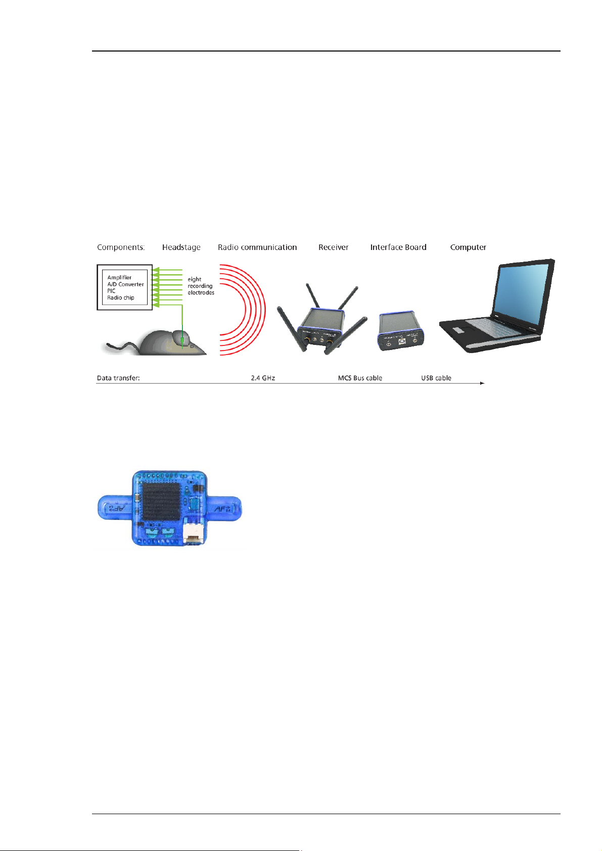
The innovative wireless recording in vivo system is the all-in one solution for amplifying,
recording, and analyzing in vivo data from four, eight, sixteen or thirty-two channels.
The bandwidth of the amplifier is 1 Hz to 5 kHz. The sampling rate is software controlled
and user defined. With a resolution of 16 bit the accuracy of your data is guaranteed.
The sampling rate is up to 40 kHz when using two electrode channels of the W4-System or four
electrode channels of the W8-System and up to 20 kHz when recording on all channels of the W4or W8-System. For the W16-System the sampling rate is 10 kHz when recording on all 16 channels
or up to 20 kHz when recording on 4 or 8 channels. Respectively, the sampling rate for the W32System is 5 kHz when using all 32 channels and up to 10 kHz when using 16, 8 or 4 channels only.
The system includes everything you need: Small sized headstage with integrated A/D converter,
digitized transmission and a powerful receiver. For controlling the easy to use software package
MC_Rack is available. With its excellent signal-to-noise ratio, the W4-, W8-, W16- or W32-
Systems are the ideal solution for spikes, LFP, EEC, ECG, and ECoG. Additional inputs to the
receiver allow the synchronization of the data with external devices.
The headstages of the systems are extremely small and lightweight and. allow the recording of
neuronal activity in freely moving animals. A/D conversion at up to 20 kHz sampling rate in the
headstages decrease the bandwidth for data transmission. Thus, it enables a long transmission
range and low power consumption at the same time. This makes flexible long time experiments
in large environments possible.
With one system it is possible to use up to four headstages in parallel for measuring several
animals one by one. With several complete systems you can record from several animals at
the same time. Even so the wireless systems can be adapted to different electrode connectors.
2
Page 7

2 Important Information and Instructions
2.1 Important Safety Advice
Warning: Make sure to read the following advice prior to install or to use the device and the
software. If you do not fulfill all requirements stated below, this may lead to malfunctions or
breakage of connected hardware, or even fatal injuries.
Warning: Obey always the rules of local regulations and laws. Only qualified personnel should
be allowed to perform laboratory work. Work according to good laboratory practice to obtain
best results and to minimize risks.
The product has been built to the state of the art and in accordance with recognized safety
engineering rules. The device may only
be used for its intended purpose;
be used when in a perfect condition.
Improper use could lead to serious, even fatal injuries to the user or third parties and damage
to the device itself or other material damage.
Warning: The device and the software are not intended for medical uses and must not be used
on humans.
Malfunctions which could impair safety should be rectified immediately.
High Voltage
Electrical cords must be properly laid and installed. The length and quality of the cords must
be in accordance with local provisions.
Only qualified technicians may work on the electrical system. It is essential that the accident
prevention regulations and those of the employers' liability associations are observed.
Each time before starting up, make sure that the mains supply agrees with the specifications
of the product.
Check the power cord for damage each time the site is changed. Damaged power cords should
be replaced immediately and may never be reused.
Check the leads for damage. Damaged leads should be replaced immediately and may never
be reused.
Do not try to insert anything sharp or metallic into the vents or the case.
Liquids may cause short circuits or other damage. Keep the device and the power cords always
dry. Do not handle it with wet hands.
Requirements for the installation
Make sure that the device is not exposed to direct sunlight. Do not place anything on top
of the device, and do not place it on top of another heat producing device. Never cover the
events, not even partially, so that the air can circulate freely. Otherwise, the device may overheat.
3
Page 8

Wireless System Manual
2.2 Guarantee and Liability
The General conditions of sale and delivery of Multi Channel Systems MCS GmbH always apply.
The operator will receive these no later than on conclusion of the contract.
Multi Channel Systems MCS GmbH makes no guarantee as to the accuracy of any and all tests
and data generated by the use of the device or the software. It is up to the user to use good
laboratory practice to establish the validity of his findings.
Guarantee and liability claims in the event of injury or material damage are excluded when
they are the result of one of the following.
Improper use of the device.
Improper installation, commissioning, operation or maintenance of the device.
Operating the device when the safety and protective devices are defective and/or inoperable.
Non-observance of the instructions in the manual with regard to transport, storage, installation,
commissioning, operation or maintenance of the device.
Unauthorized structural alterations to the device.
Unauthorized modifications to the system settings.
Inadequate monitoring of device components subject to wear.
Improperly executed and unauthorized repairs.
Unauthorized opening of the device or its components.
Catastrophic events due to the effect of foreign bodies or acts of God.
2.3 Operator's Obligations
The operator is obliged to allow only persons to work on the device, who
are familiar with the safety at work and accident prevention regulations and have been
instructed how to use the device;
are professionally qualified or have specialist knowledge and training and have received
instruction in the use of the device;
have read and understood the chapter on safety and the warning instructions in this manual
and confirmed this with their signature.
It must be monitored at regular intervals that the operating personnel are working safely.
Personnel still undergoing training may only work on the device under the supervision
of an experienced person.
4
Page 9
13 5
16 5
16
16
3 Hardware
3.1 Headstage
The headstage is the first of the three elements of the Wireless-System. The headstage is
extremely small and lightweight and allows the recording of neuronal activity in freely moving
animals. The A/D conversion with a variable sampling rate of 1, 2, 4, 5, 10 and 20 kHz when using
all channels and 25, 32 and 40 kHz when using four or less than four channels of the W8-System
or one or two channels of the W4-System. For the W16-System the maximal sampling rate is 10
kHz when using all 16 channels or up to 20 kHz when recording on 4 or 8 channels. Respectively,
the sampling rate of the W32-System is 5 kHz when using all 32 channels and up to 10 kHz when
using 16, 8 or 4 channels only.
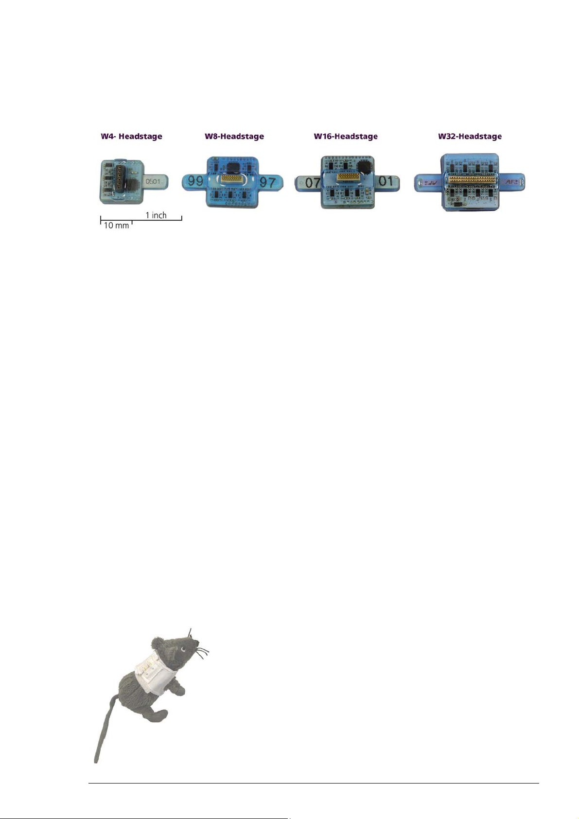
Please see the table for the dimensions and weights of the headstages. Thus, the headstage
is lightweight and reasonable for the free moving laboratory animal.
Dimensions /
Weight
W4-System 13 (+ antenna)
W8-System 16 (+ antenna)
W16-System 16 (+ antenna)
W32-System 16 (+ antenna)
The headstage is designed energy efficient. The standard battery (100 mAh) of a headstage
permits continuous recording of all channels for more than 2 hours. Recharging is then realized
via USB. When doing experiments with animals insensitive to weight, MCS also offers larger
batteries, which provide longer recordings. For the W4-System a smaller 30 mAh battery (1.5 g)
is available. Please contact Multi Channel System MCS GmbH for more information on battery
options.
The battery can be fixed on the top side of the headstage or can be stored in a special backpack
adapted to the size of the animal.
W in mm D in mm
H in mm Weight
2 (+ battery)
3 (+ battery)
6.5
7.5
4 (+ battery)
5 (+ battery)
5
Page 10
Wireless System Manual
The connector of the headstage is connected to the electrode which is implanted into the brain
of the laboratory animal. The external connector of the implanted electrode is fixed, for example
with dental cement.
For maximum flexibility, MCS offers headstages with connections to all probes on request.
The headstage records analog signals from the electrodes. The integrated A/D converter converts
the analog signals into digital signals, which are sent to the receiver via radio communication
in the 2.4 GHz frequency band. Thus, it enables a long transmission range and low power
consumption at the same time. This makes flexible long time experiments in large environments
possible.
The headstage and the receiver should be placed near to each other in the experimental setup.
They may have a distance to each other of about 5 m without data loss.
First Tests of the Headstage with a ME/W-Signal Generator
For initial testing the Wireless-System you do not have to operate with a laboratory animal,
but you can use a signal generator.
The ME/W-System Signal Generator is a convenient tool for the user. As a variable substitute
for laboratory animals you can use the ME/W-SG as you would set up a research experiment.
That means you can test your Wireless-System and data acquisition settings without using valuable
biological samples. It has the advantage that you do not need an animal, you reduce the number
of animal experiments and save laboratory equipment. Please connect the headstage to the signal
generator as shown on the picture. Please read the data sheet in the Appendix for operating the
ME/W-Signal Generator device.
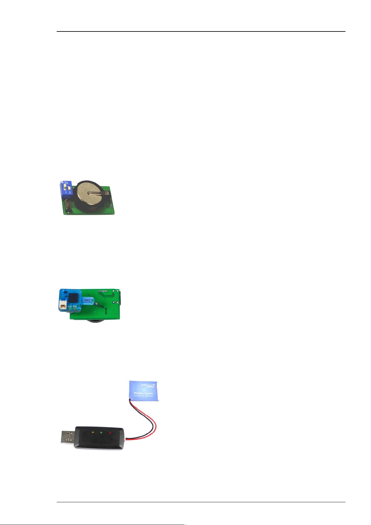
Charging Set
The charging set for the storage battery works via any USB connector. To recharge the battery,
please connect the charging set to an USB port of the computer and plug the battery into the
back of the charger.
The red LED on top indicates that the device is on. The yellow LED indicates that the storage
battery is being recharged. After approximately one hour the green LED indicates the end
of process.
6
Page 11
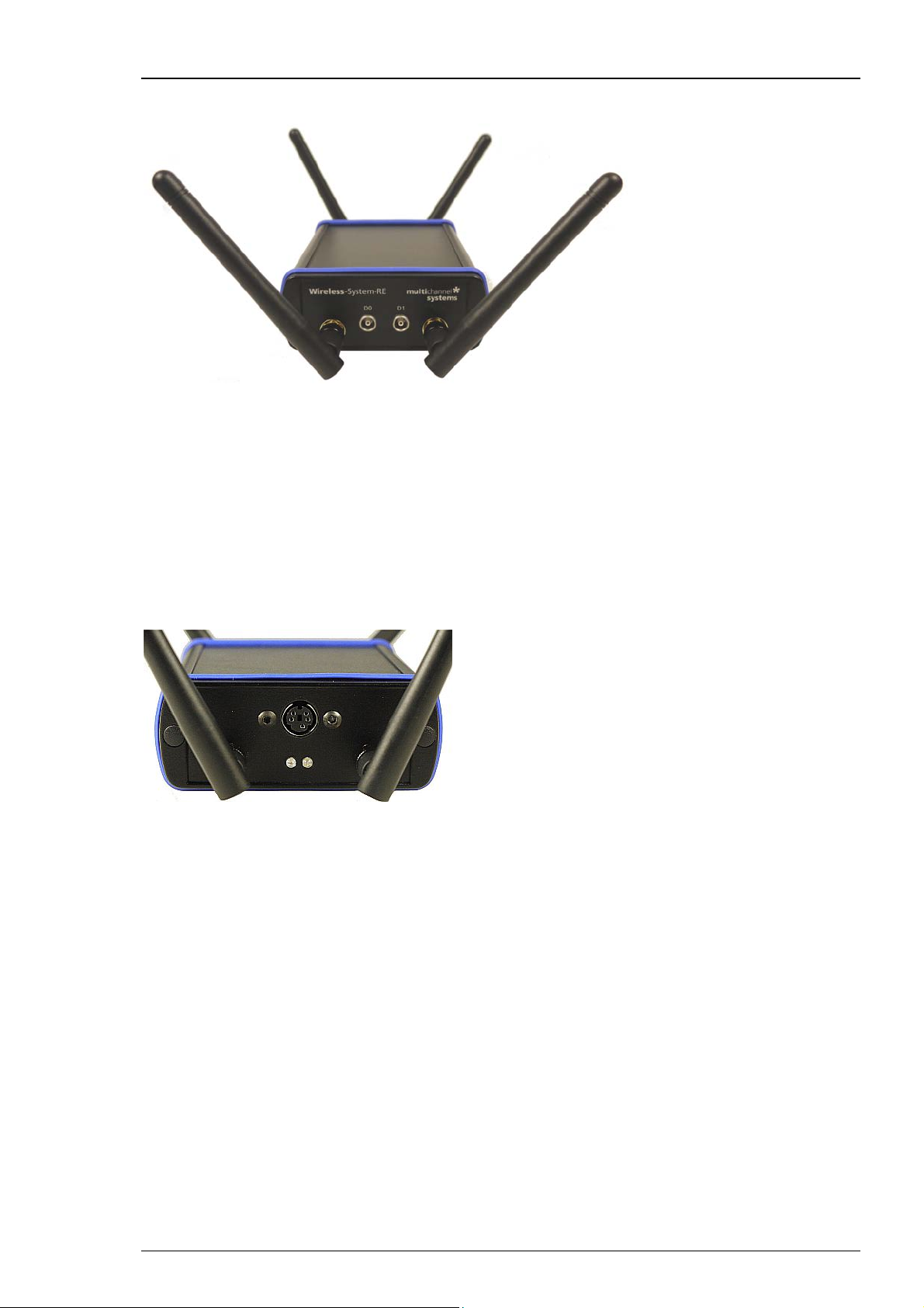
3.2 Receiver
The receiver is the second element of the Wireless-System.
The receiver of the Wireless-System receives the digitized signals sent from the headstage
in a distance of about 5 m. The device is equipped with four antenna to prevent data loss.
Two Lemo connectors on the front panel, labeled with D0 and D1 are available to feed in TTL
signals for synchronization of the Wireless-System with other devices. For example, when passing
a light barrier, feeding the animal or other events which manipulate the experiment. The check
box "Digital Input Channel" in "Data Source Layout" must be activated when using the external
digital data, otherwise it is not possible to display the external data on the MC_Rack screen.
Please read chapter “Starting MC_Rack”.
Hardware
The two LEDs on the back of the receiver indicate the status of the system: The green LED
indicates that power is on, the system is ready for recording. The blue LED flashes in a slow
frequency, when the system is in stand by modus. The blue LED flashes in a fast frequency
during data recording.
The receiver and the interface board respectively do not need an own power supply. They
are powered by the USB high speed cable connected to the data acquisition computer.
7
Page 12

Wireless System Manual
3.3 USB Interface
The USB interface board is the third element of the Wireless-System.
The interface board is connected to the receiver with a MCS Bus cable, which is about 5 m long.
Longer cables are delivered on request. The advantage is that the interface board can be placed
near to the data acquisition computer in a different room than the experimental laboratory and
the test animal will not be disturbed in excess of the experimental setup and the scientist. The
connection to the data acquisition computer is realized via USB high speed cable, respectively.
Two additional Lemo connectors are available to feed in TTL signals for synchronization of the
Wireless-System with other devices, for example when the test animal is passing a light barrier,
when the animal is feeded or other events, which are manipulating the experiment. The check
box "Digital Input Channel" in "Data Source Layout" must be activated when using the external
digital data, otherwise it is not possible to display the external data on the MC_Rack screen.
Please read chapter “Starting MC_Rack”.
The two LEDs on the back of the interface board indicate the status of the system: The green
LED indicates that power is on. If the green LED flashes, you have to install the newest version
of MC_Rack software, which automatically will update your system with the drivers needed.
When the hardware is successfully installed, the green LED illuminates stable. The blue LED
flashes in slow frequency, when the system is in stand by modus. The blue LED flashes in fast
frequency during data recording.
The interface board does not need an own power supply. It is powered via USB high speed cable
by the data acquisition computer.
8
Page 13

4 Software
4.1 Installing MC_Rack
The data acquisition computer with the MC_Rack program comes preinstalled and preconfigured
by MCS for a flawless operation. You should contact your local retailer for assistance if you want
to install additional hard- or software, or if you want to replace the computer, as incompatibilities
of hardware components or software settings with MC_Rack may occur.
Caution: You have acquired a high performance data acquisition and analysis computer. Do not
modify the system, do not install new hard- or software, or another operating system without
asking MCS or your local retailer for advice. Especially do not install virus scanners or firewalls
because these programs are known to interfere with the data transfer to the hard disk. MCS
cannot guarantee that a modified system is fully operational. Even data loss may occur.
System requirements
Software:
One of the following Microsoft Windows ® operating systems is required: Windows 7, Vista,
or XP (English and German versions supported) with the NT file system. Other language versions
may lead to software errors.
Hardware: System of implanted electrodes, headstage, receiver and interface box.
The Wireless-System. (Not required for offline analysis or demo mode). If no data acquisition
is present, MC_Rack opens in a simulation mode. A computer with low performance may lead
to performance limits more often; therefore, MCS recommends an up-to-date computer. Please
note that there are sometimes hardware incompatibilities of the Wireless-System and computer
components; or that an inappropriate computer power supply may lead to artifact signals.
Please contact your local retailer for more information on recommended computer hardware.
Important: You need to have installed the latest Wireless-System driver to operate the system,
which is automatically installed with MC_Rack. The installation may be invalid if the WirelessSystem does not respond. Please contact Multi Channel Systems or your local retailer in this case.
9
Page 14

Wireless System Manual
Recommended operating system settings
The following automatic services of the Windows operating system interfere with the data
storage on the hard disk and can lead to severe performance limits in MC_Rack. These routines
were designed for use on office computers, but are not very useful for a data acquisition
computer.
Turn off Windows System Restore.
Turn off automatic Windows Update.
Deselect Windows Indexing Service for all local disks.
Turn off Optimize hard disk when idle (automatic disk fragmentation).
It is also not recommended to run any applications in the background when using MC_Rack.
Remove all applications from the Autostart folder.
Be careful when using a Virus Scanner. These programs are known to disturb MC_Rack,
and even data loss may occur.
When using a Wireless-System it is recommended to connect a high performance computer
with a separate hard discs for program files and data storage. The provided possibility to make
long term experiments with a sample rate of up to 40 kHz needs high memory capacity. Please
remove data and defragment the hard disc regularly to ensure optimal performance.
Warning: The operating system settings of the data acquisition computer were preconfigured
by MCS and should not be changed by the user. Changing these settings can lead to program
instabilities and data loss.
Installing the software
Please check the system requirements before you install the software. MCS cannot guarantee
that the software works properly if these requirements are not fulfilled.
Important: Please make sure that you have full control over your computer as an administrator.
Otherwise, it is possible that the installed software does not work properly.
1. Double-click Setup.exe on the installation volume.
The installation assistant will show up and guide you through the installation procedure.
2. Follow the instructions of the installation assistant.
The Wireless-System driver and MC_Rack are installed (or updated) automatically.
10
Page 15
4.2 Starting MC_Rack
Connect, for example, a W8-System via USB high speed cable to the data acquisition computer.
Open MC_Rack program.
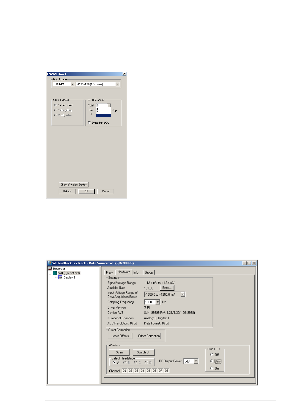
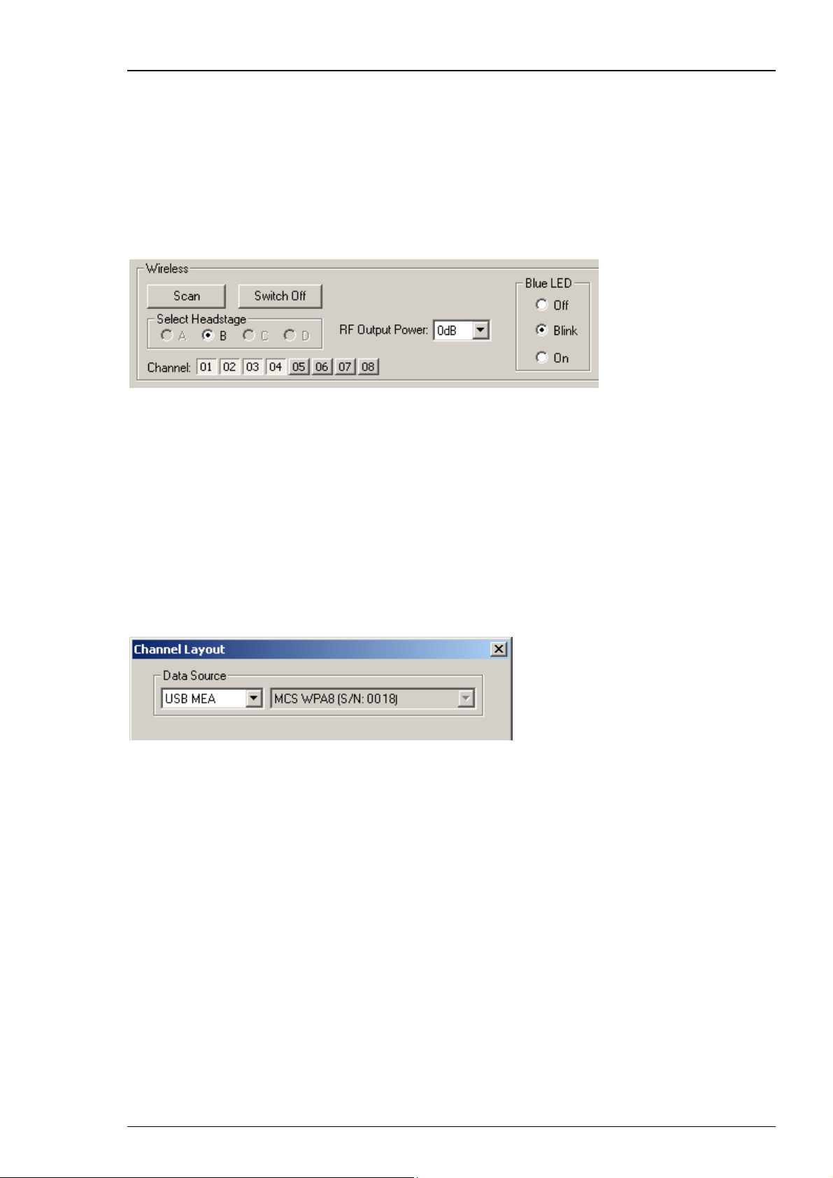
In "Edit" menu choose "Data Source Setup". The following “Channel Layout” dialog appears.
Software
Select USB-MEA in the left drop down menu of "Data Source". The W8-System "MCS WPA8
(S/N xxxx)" will automatically appear in the right drop down menu. In "Source Layout" the check
box “1 dimensional” is predefined and the "Number of Channel" in total is “8”.
Enable the check box "Digital Input Channel" if you want to display external TTL signals, feeded
into the W8-System via Lemo connectors on receiver and interface board. Deselect the check box,
if you do not need additional digital channels.
Add the W8-System and a display to the virtual rack. Click "Hardware" tab.
11
Page 16
Wireless System Manual
There is an additional window in “Hardware” tab for the W8-System called “Wireless”,
and the MC_Rack display shows an additional status line
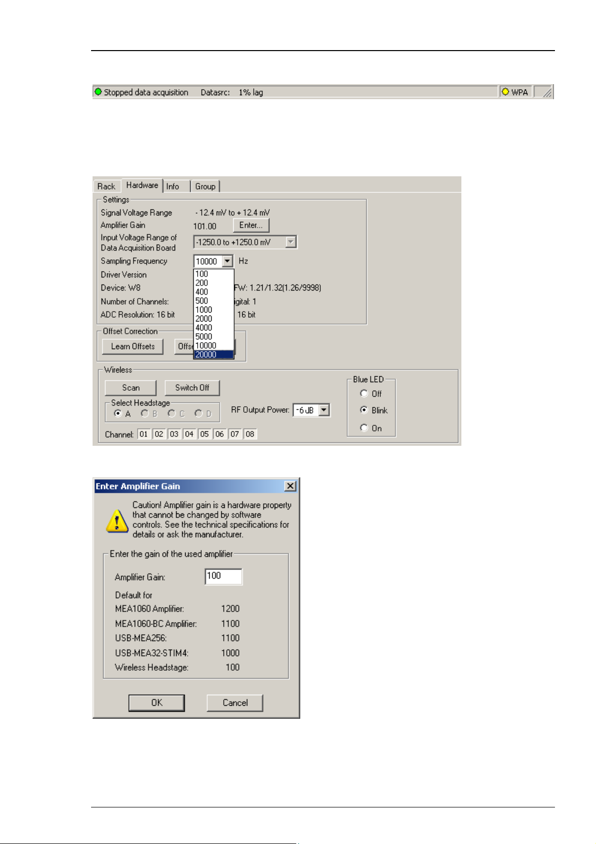
The “Sampling Frequency” of the system depends on the number of channels which are in use.
When recording with all eight available channels the sampling rate is limited to 20 kHz.
Recording with one to four channels only is possible with a sampling frequency of up to 40 kHz.
Click the “Sampling Frequency” drop down menu and select the desired sampling rate.
Click “Amplification Gain” button “Enter”.
The “Enter Amplifier Gain” dialog appears. The fixed amplifier gain of 100 for the wireless
headstage is displayed in the list. Please type 100 into the window above.
12
Page 17
Software
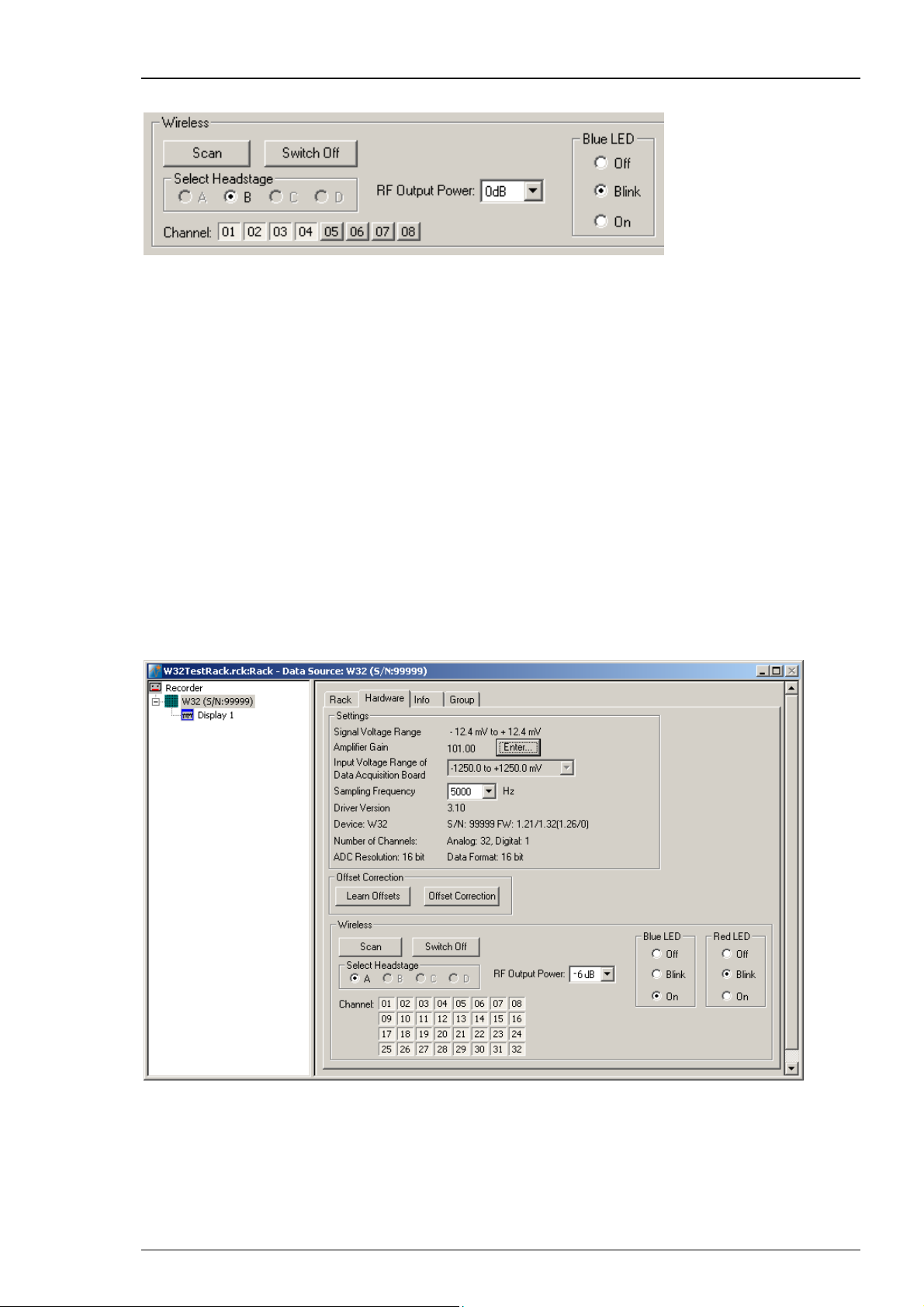
Wireless Window
The additional window “Wireless” is for software control of the wireless system. In “Select
Headstage” you can select one of the four headstages A, B, C, and D if more than one headstage
is connected to the system. After pressing the button “Scan” the receiver scans which headstages
are available. Then the user is able to select the desired headstage.
The appropriate channels of the selected headstage are chosen by clicking on the channel
number. In the Wireless Window the selected channels appear pressed in as shown on the
screenshot, Channel No 05, 06, 07, and 08.
To minimize energy consumption, you can switch off the headstage by clicking the button
“Switch Off”. The headstage changes from “Stand By” modus into the “Switch off” modus.
From “Switch off” modus it is not possible to switch a headstage back on via software control.
The blue LED mounted on the headstage of the W8-System indicates the recording phases.
It can be switched into three modes via radio button. Select “Off” if the laboratory animal
is disturbed by the light. Switching off the LED will save a little bit of energy. Select “Blink”
and the LED flashes during recording. Select “On” and the LED will be on permanently.
This feature can be used, for example for camera tracking.
The W32-headstage is equipped with two LEDs, the blue one and an additional red one.
The user has the same options to set the red LED. Both LEDs together improve the camera
tracking, because with two LEDs it is possible to track the orientation of the headstage.
Choose a “RF Output Power” value from the drop down menu. The smaller the value, for example
–6 dB, the longer the storage battery will support the recording, but the smaller the distance
between animal and receiver.
13
Page 18
Wireless System Manual
Strategies for Saving Energy
The standard recording time with a fully charged battery is 120 minutes at 20 kHz and 0 dB
output power in a range of up to 5 m between headstage and receiver. Please read chapter
"Power Consumption" in the Appendix.
To prolong the recording time until the battery has to be recharged on the one hand you can
decrease the sampling frequency, on the other hand you can decrease the RF output power.
For example, when recording with 500 Hz sampling frequency you save 100 mA per hour and
the energy of the storage battery lasts for a recording time of eight hours. This may be useful
for experiments in epilepsy research.
For example, when recording with –18 dB at 20 kHz sampling frequency you save approximately
50 mA per hour, that means the recording time is 30 minutes longer compared to the time when
recording with 0 dB. However, the transmission power will decrease respectively.
Starting the W8-System again after switching off via software
To switch the headstage back on after pressing the button "Switch Off", the user has two
possibilities: Use the infrared flasher and illuminate the receiver LEDs next to the battery
connector. Then press the button "Scan" in "Wireless Window" to reconnect to the headstage.
The second possibility is to unplug the battery from the headstage manually and to reconnect
headstage and battery again.
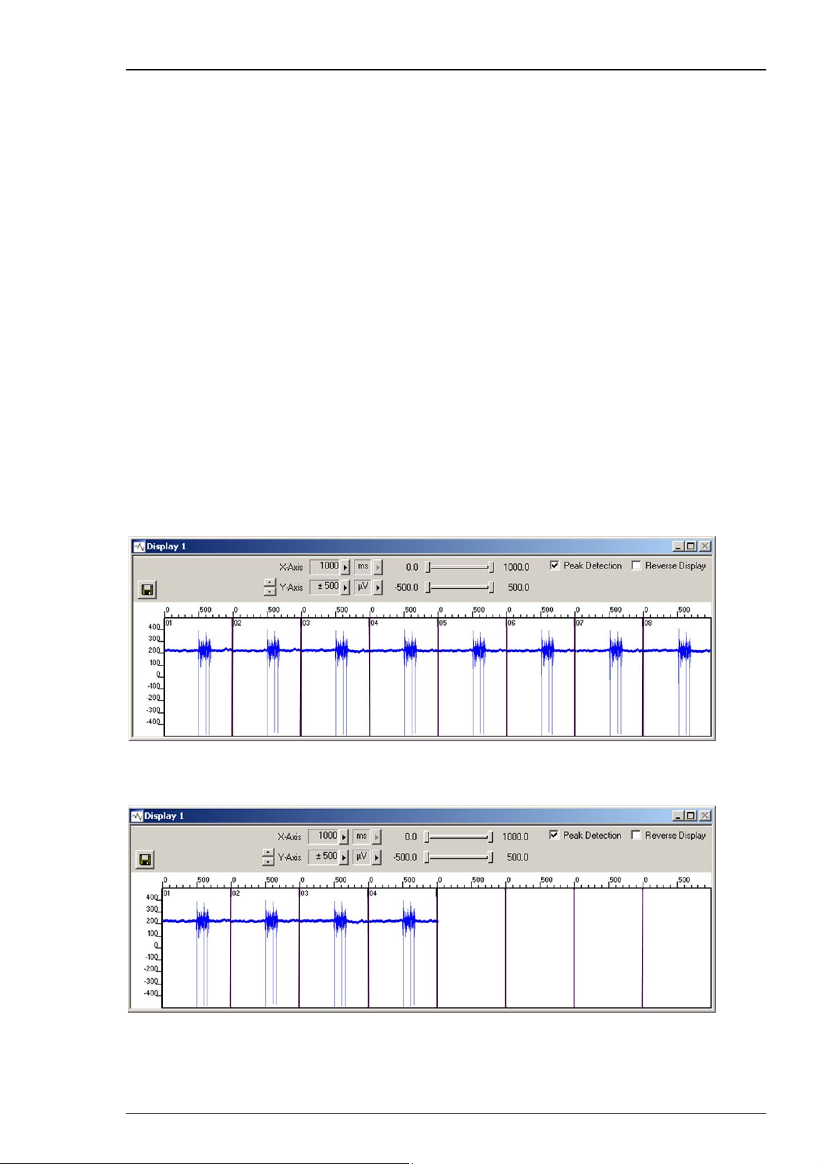
Add a display to your rack.
The number of displayed channels depends on the number of selected channels in “Wireless”
of “Hardware” tab.
For detailed information about the use of MC_Rack, please read the MC_Rack manual.
14
Page 19

Software
Software Settings when Using different Types of Headstages with one Wireless-System
May be you will use your wireless system in different experimental setups, that is for example, first
with an eight channel headstage and then with a four channel headstage. In this case you have to
adapt the wireless system to the variable hardware requirements via MC_Rack software. MC_Rack
needs specified driver units for each hardware component, which must be loaded when changing
the type of the headstage.
The following example describes how to change a W8-System to a W4-System. The W8-System
is already connected to the data acquisition computer and installed.
Open a new empty MC_Rack file and select “Data Source Setup”. The system with eight channels
will be found and displayed.
Click the button “Change Wireless Device”.
Select the W4-System from the drop down menu “Wireless Device Type” and confirm with “OK”.
15
Page 20

Wireless System Manual
The installation lasts a few seconds.
Please wait until the new driver has been loaded and the headstage is internally switched.
If you install the W4 headstage for the first time, a hardware installation assistant will appear.
Please follow the installation instructions. If the drivers for the W4-System have been installed
before, ignore this step and click the “Refresh” button in the “Data Source Setup” dialog.
16
Page 21

Software
After the hardware installation process, please click the “Refresh” button in the “Data Source
Setup” dialog to update hardware and software.
The W4-System will now be available in the “Data Source Setup” dialog. Select the desired
headstage device from the drop down menu and start working as described above.
17
Page 22

Page 23

5 Operating a Wireless System
5.1 Experimental Setup
First step to set up an experiment with the wireless system is to implant an electrode into the
laboratory animal. The electrode has to be fixed, for example with cement used in dental technic,
to guarantee a tight position of the electrode in the desired area of the brain. The electrode
connector must be available on the skin surface of the animal. Implant a ground option
additionally, if necessary.
Use of the Reference and Ground Electrodes
For in vivo experiments it is necessary to provide a good option for grounding (GND) and a well
placed reference (REF) electrode. Therefore all headstages of the Wireless-System are equipped
with electrical isolated pins for a ground and a reference electrode.
Important: For good signal quality you should use dedicated reference and ground electrodes!
The reference electrode is used to measure the relative potential differences in relation to the
recording electrodes. It should be out of a similar or the same material as the recording electrodes
and it should be of comparable size. The reference is ideally placed near the recording electrodes,
but not in active tissue.
The signals from all electrodes are amplified and then each signal from the recording electrodes
is compared to the signal from the reference electrode. The difference is measured by the analog
to digital converter (ADC) and digitized.
When external interferences, for example heartbeats, muscle potentials, breathing, disturb the
measurements, both, the recording and the reference electrodes measure the same disturbance
and the noise signal is removed because only the difference between recording and reference
electrode is digitized and transmitted (Common Mode Rejection).
19
Page 24

Wireless System Manual
To make sure that the animal and the headstage are set to the same electrical potential,
a grounding connection is also necessary. A good ground option is usually a large conductor,
such as a screw or a silver wire implanted under the skin of the animal.
Experimental Setup
Connect the receiver to the USB interface, and the USB interface to the data acquisition computer.
Switch on the computer and start the MC_Rack program.
Make sure that the storage battery of the headstage is charged and plugged in properly.
The battery can be fixed on top of the headstage with a magnet or it can be stored in a special
backpack on the back of the animal.
Connect the wireless headstage to the electrode connector on the skin surface of the test animal.
Connect the receiver via MCS Bus cable to the interface board and the USB cable to the data
acquisition computer. The cable between receiver and interface board is 5 m, longer cables
are available on request. The USB cable between USB interface board and computer is 2 m.
The receiver and the interface board are powered by the computer.
The software MC_Rack is for data acquisition and data analyzing. Please read the MC_Rack
manual for detailed information.
20
Page 25

5.2 Operating Modes
Recording Mode
Set up all components of the Wireless-System. Start MC_Rack and add the Wireless-System as data
source. Please read chapter “Starting MC_Rack”. Define the amplifiers gain of 100 and select the
sampling frequency in the “Hardware” tab.
Make sure the storage battery is completely charged. Connect the battery to the white connector
on the headstage.
In the “Wireless” window of the MC_Rack “Hardware” tab, press the button “Scan” to find the
headstages available. After that the user is able to select the desired headstage (A, B, C, D) when
using more than one headstage. All eight recording channels are selected by default. Deselect the
channels you do not need.
The Wireless-System is in recording mode now. You can start recording by pressing the “Start”
button in MC_Rack. The storage battery allows recording of approximately two hours.
Operating a Wireless System
After the experiment stop the recording by pressing the “Stop” button.
The “Recording Mode” is indicated by a high frequent flashing of the blue LED on the headstage.
Stand By Mode
To save energy the Wireless-System changes from “Recording Mode” into “Stand By Mode”
immediately after stopping the recording. The “Stand By Mode” allows starting the recording
again at any time. In this mode the storage battery lasts for up to eighty days depending on the
recording time before.
The “Stand By Mode” is indicated by a very weak and slow flashing of the blue LED on the
headstage.
Switched Off Mode
To save more energy than in “Stand by Mode” you can switch the headstage off.
In the “Wireless” window of the MC_Rack “Hardware” tab, please press the button “Switch Off”
to switch off the selected headstage.
In this mode the battery lasts for up to 130 days depending on the recording time before.
Switching the headstage on from this mode is not possible via software control. To do so the user
has two possibilities: Use the infrared flasher and illuminate the receiver LEDs next to the
connector for the battery. The flasher and the headstage should have a distance of about 5 to 10
cm. The second possibility is to unplug the battery from the headstage manually and to reconnect
headstage and battery again.
Then press the button "Scan" in "Wireless Window" to reconnect to the headstage.
21
Page 26
Wireless System Manual
Operating up to four Headstages rotatory with one Wireless-System
It is possible to operate up to four different headstages connected to one Wireless-System
in a rotatory system. The headstages are discriminated via frequency band for the radio
communication. Each headstage is labeled with a letter (A, B, C, D). Please see the bill of delivery
for the assignment of the headstage and the frequency band. (When using one single headstage
only, the headstage is automatically A without a label.)
After pressing the button “Scan” the receiver scans which headstages are available.
Then the user is able to select the desired headstage.
After recording from the first headstage, you can choose the second headstage in the “Wireless”
window, the third and the fourth.
Operating up to four Wireless-Systems in parallel with one Computer
It is also possible to operate up to four different complete Wireless-Systems with one data
acquisition computer. This way, you can experiment with up to four laboratory animals
contemporaneous. The headstages are discriminated via frequency band for the radio
communication again. Headstages and related receivers are labeled for differentiation.
Set up the Wireless-Systems and connect them to the data acquisition computer.
Start as many instances of MC_Rack software as you need. In “Data Source Setup”
assign the Wireless-Systems via serial number to the instances of MC_Rack.
22
Page 27

6 Troubleshooting
6.1 Troubleshooting
Most problems occur seldom and only under specific circumstances. In most cases, it is only
a minor problem that can be easily avoided or solved.
If the problem persists, please contact your local retailer. The highly qualified staff will be glad
to help you. Please inform your local retailer as well, if other problems that are not mentioned
in this documentation occur, even if you have solved the problem on your own. This helps other
users, and it helps MCS to optimize the instrument and the documentation.
Please pay attention to the safety and service information of chapter "Important Safety Advice".
Multi Channel Systems has put all effort into making the product fully stable and reliable,
but like all high-performance products, it has to be handled with care.
6.2 Error Messages
The headstage sends signals to the receiver in 2.4 GHz frequency band. That is why devices,
working in the same frequency band may disturb the data communication between headstage
and receiver. Please do not use, for example, a mobile phone equipped with blue tooth
or a WLAN connection or a microwave in the vicinity of headstage and receiver otherwise
it may cause troubles in data transfer.
Important: For compatibility reasons it is not recommended to use an USB hub to connect
the Wireless-System to your computer.
23
Page 28

Page 29
7 Appendix
7.1 Wireless-System Config
The tool "Wireless-System Configuration" helps to configure new wireless headstages to a present
setup and to arrange the assignments of headstages of several systems for simultaneous use.
Additional it is possible to change the high pass settings of the respective Wireless-System.
Important: Please always run the Wireless-System Config tool before you start working with
a new headstage!
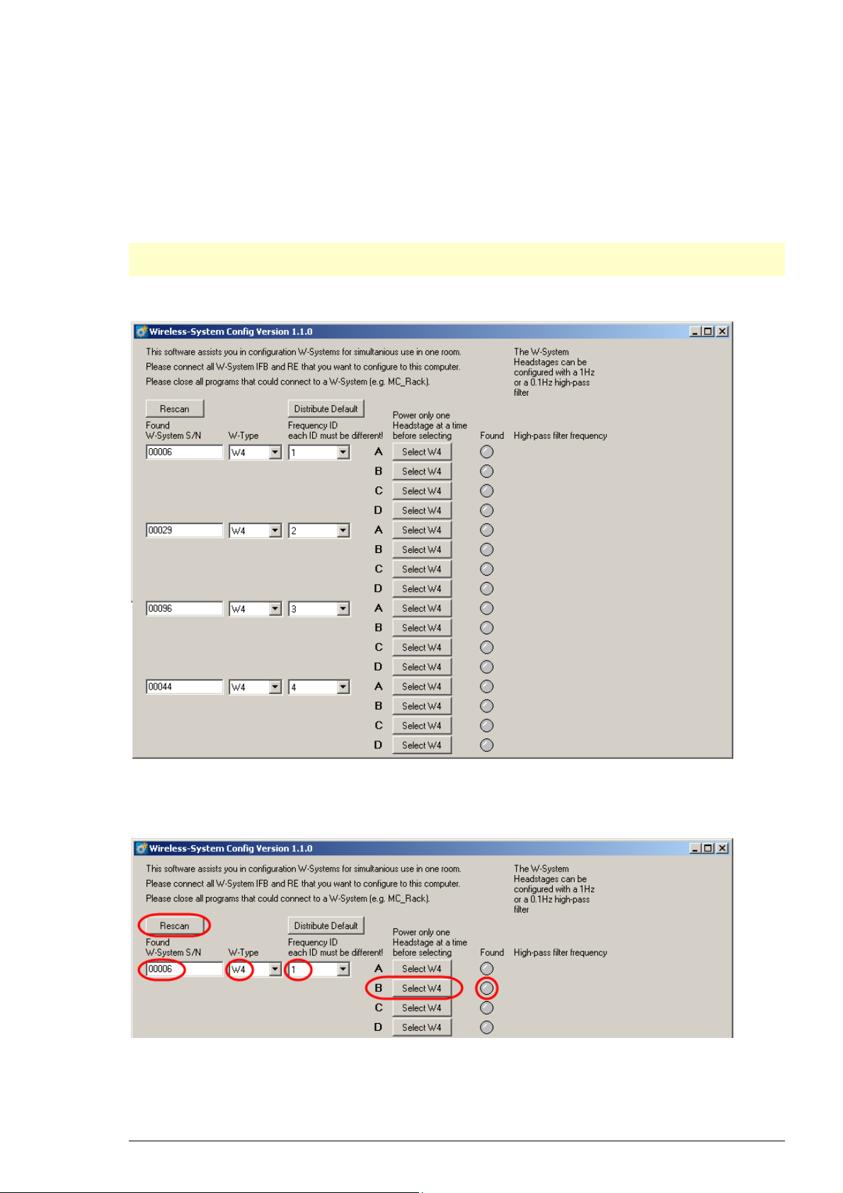
Main Window
The screenshot above shows the main window, when the maximal number of four WirelessSystems are connected to one data acquisition computer. To each system you can connect
up to four headstages.
In the header of the main window you are informed about aims and purposes of the software
tool.
25
Page 30

Wireless System Manual
At first the software detects all Wireless-Systems which are connected to one data acquisition
computer. In "Found W-System SN" the systems are defined by the serial number. You can find
the serial number on the bottom of the receiver and interface board. It is possible to connect,
for example, one W4- and one W8-System. Please set the number of channels of your system
from the "W-Type" drop down menu. Each connected system needs to have a "Frequency ID"
and "each ID must be different".
The letters A, B, C, D denote the connected headstages of the respective system. These letters
are the same as they are used in the MC_Rack hardware dialog.
The Wireless-System Config tool is able to assign one headstage after the other to the respective
Wireless-System.
Please connect the desired headstage to the battery and press the desired button A, B, C,
or D
in the "Found" button
to assign the headstage to A, B, C or D, which is indicated by the green color
.
To change your selection you can simply choose a new assignment. The information whether
the headstage is A or C for example, will be permanently stored on the headstage and can be
changed at any time. Power the next headstage and assign it to another letter or to another
system with a different "Frequency ID" the same way as described above.
In the screenshot above, different headstages are assigned to the four Wireless-Systems
connected to the data acquisition computer, defined by the "Frequency ID" and the labels
"A", “B”, “C” and "D".
26
Page 31
Appendix
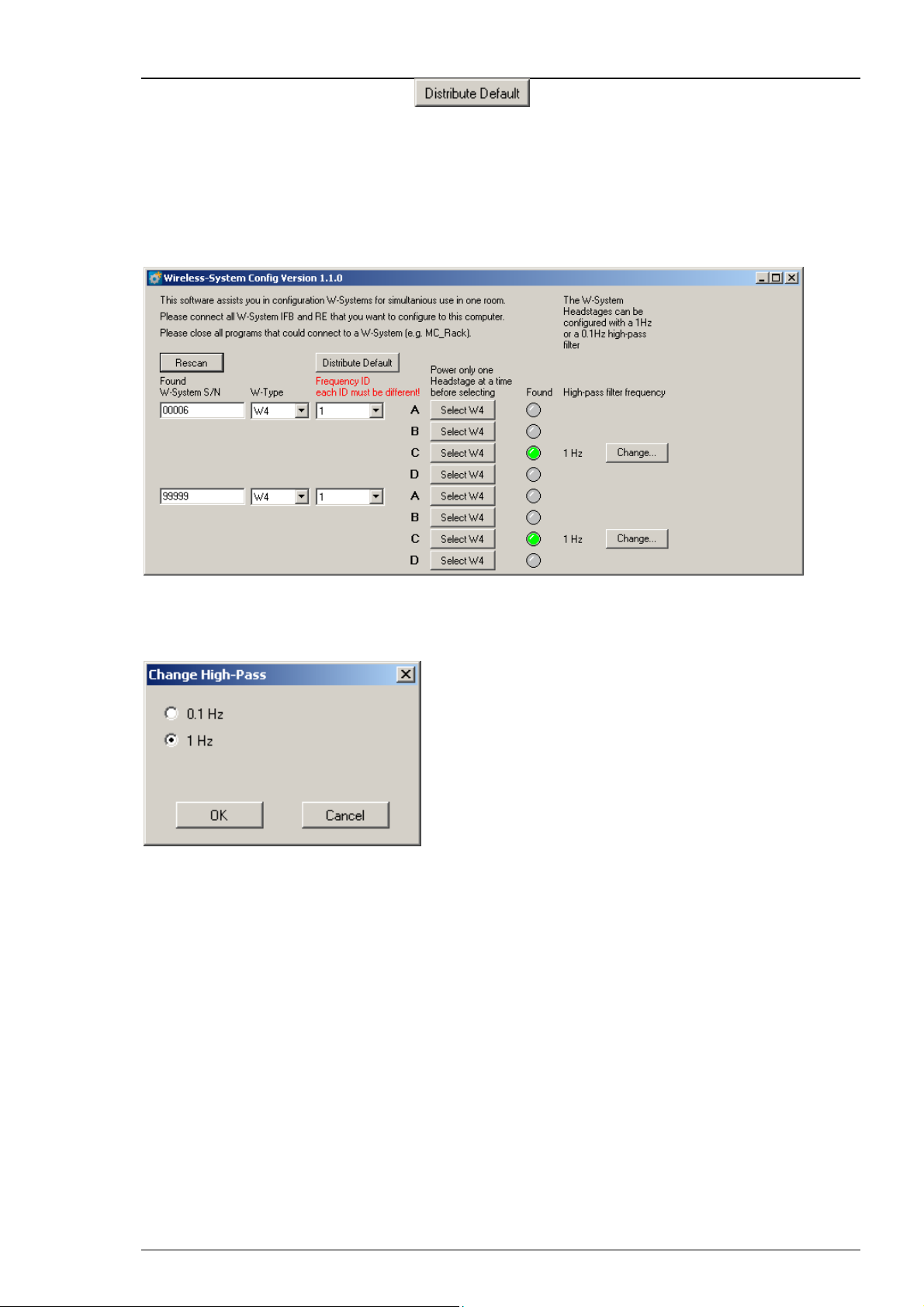
Click the button "Distribute default" to keep the "Frequency ID" in a line,
ID 1 to ID 4.
If you try to give the same frequency ID to different systems you get an error message.
"Frequency ID each ID must be different!". Please choose another ID.
When using a second data acquisition computer nearby to record from an additional wireless
systems, please make sure that the frequency IDs differ from each other. Otherwise the systems
will interfere.
To change the high pass filter, press the button "Change". The "Change High Pass" dialog
will open. Click the radio button of the desired frequency 0.1 Hz or 1 Hz. This information
will be permanently stored on the headstage.
27
Page 32

Wireless System Manual
To Do Checklist before start working with a Wireless-System
in a new configuration:
1. Start the Wireless-System Config program. The main window opens.
2. When connecting more than one Wireless-System to the data acquisition computer the main
window appears twice or more. Please make sure that each system on one data acquisition
computer has a different frequency ID. Your Wireless-System(s) is / are now detected by
the Wireless-System Config tool. The serial number of your receiver(s) is / are displayed
in "Found Wireless-System S/N".
3. Choose your W-Type from the drop down menu, which possibly is already chosen.
4. Now please connect the first headstage to a battery. The headstage switches on, that means
the blue light flickers
Important: Configure only one headstage at a time!
6. Press "Select W4" to define the headstage as "A", "B", "C"; or "D" . This step determines
the frequency band of this particular headstage.
7. The established connection is indicated by the green color of the "Found" button.
8. Disconnect the first headstage, which is configured now. Connect the next headstage
and configure it either to the same Wireless-System (receiver) with the same frequency ID,
but to another frequency A, B, c or D. Or you connect the headstage to another Wireless-Systems
and perform the same procedure as described above.
28
Page 33

7.2 Technical Support
Please read the "Troubleshooting" part of the manual or help first. Most problems are caused
by minor handling errors. Contact your local retailer immediately if the cause of the trouble
remains unclear. Please understand that information on your hardware and software
configuration is necessary to analyze and finally solve the problem you encounter.
If you have any question or if any problem occurs that is not mentioned in this documentation,
please contact your local retailer. The highly qualified stuff will be glad to help you.
Please keep information on the following at hand
Description of the error (the error message text or any other useful information) and
of the context in which the error occurred. The more information on the actual situation
you can provide, the easier it is to track the problem.
The serial number of the device. You will find it on the bottom side of the main unit.
The software of MC_Rack version you are currently using. On the "Help" menu,
click "About MC_Rack". The displayed dialog box shows the version number.
The hardware version of the Wireless-System you are currently using is displayed
in the “Hardware” tab of the starting dialog.
The operating system and service pack number on the connected computer.
Appendix
The hardware configuration (microprocessor, frequency, main memory, hard disk)
of the connected computer. This information is especially important if you have modified
the computer or installed new hard- or software recently.
29
Page 34

Wireless System Manual
7.3 Technical Specifications
The Wireless-System is a 4-, 8-, 16- or 32-channel wireless in vivo system with headstage,
receiver and interface board. Analog signals are converted in digital data streams in real-time.
Warning: The devices may only be used together with Wireless-Systems from Multi
Channel Systems MCS GmbH, and only for the specified purpose. Damage of the devices
and even fatal injuries can result from improper use. Do not open the receiver or the
interface box and do not change hardware configuration as it could lead to improper
behavior of the system.
General characteristics
Operating temperature 10 °C to 50 °C
Storage temperature
0 °C to 50 °C
Relative humidity 10 % to 85 %, non-condensing
Headstage
Dimensions (W x D x H)
4 channels: 13 mm (+antennae) x 13 mm x 5 mm (+ battery)
8 channels: 16 mm (+antennae) x 16 mm x 5 mm (+ battery)
16 channels: 16 mm (+antennae) x 16 mm x 6.5 mm (+ battery)
32 channels: 16 mm (+antennae) x 16 mm x 7.5 mm (+ battery)
Weight
4 channels: approximately 2 g (+ battery)
8 channels: approximately 3 g (+ battery)
16 channels: approximately 4 g (+ battery)
32 channels: approximately 4 g (+ battery)
Number of analog
4, 8, 16 or 32
recording channels
Amplifier integrated in the headstage
Bandwidth 1 Hz to 5 kHz (0.1 Hz on request)
Resolution 16 bit
Input voltage range + / - 12.4 mV
Sampling rate
Distance
5 m guaranteed
for wireless link
30
Page 35

Storage battery
Storage battery Lithium polymer, rechargeable
Appendix
Storage battery life until
recharge (100 mAmh)
4 channels: 3.5 hours (recording @ 20 kHz)
8 channels: 2 hours (recording @ 20 kHz)
16 channels: 2 hours (recording @ 10 kHz)
32 channels: 1.3 hours (recording @ 5 kHz)
for all channels: 80 days (in stand-by mode)
Dimensions (W x D x H)
of battery
17 mm x 11 mm x 3 mm (30 mAh battery)
26 mm x 19.5 mm x 2.3 mm (100 mAh battery)
26 mm x 20 mm x 4.5 mm (200 mAh battery)
27.5 mm x 19.5 mm x 5 mm (300 mAh battery)
Weight of battery
Approx. 1.5 g (30 mAh battery)
Approx. 3 g (100 mAh battery)
Approx. 5 g (200 mAh battery)
Approx. 7 g (300 mAh battery)
Recharging Device
Dimensions (W x D x H) 55 mm x 20 mm x 10 mm
Period of charging
1 hour
Power USB powered
Receiver
Dimensions (W x D x H) 110 mm x 78 mm x 29 mm
Frequency band 2.4 GHz
Impedance of antennae 50 Ohm
Interface Board
Dimensions (W x D x H) 110 mm x 78 mm x 29 mm
Control interface USB 2.0 High Speed
Software
Operating system Microsoft Windows ® 7, XP or Vista with NTFS,
English and German version supported
MC_Rack program Data acquisition
Version 4.1.0 and higher
and analysis software
MC_DataTool program
Data export software
Version 2.6.2 and higher, Axon binary file
(*.abf), ASCII file (*.txt), binary file (*.raw)
31
Page 36

Wireless System Manual
7.4 Pin Layout
32
Page 37

multichannel
systems
Wireless Headstages
Technical Specifications of Wireless Headstages
W4-Headstage W8-Headstage W16-Headstage W32-Headstage
Single row connector Omnetics or single row con. Omnetics connector Omnetics connector
*
Technical Specifications
Headstage
Number of channels 4, 8, 16 or 32
Dimensions (W x D x H) W4 13 x 13 x 5
(w/o antennae in mm) W8 16 x 16 x 5
W16 16 x 16 x 6.5
W32 16 x 16 x 7.5
Weight (w/o battery) W4 2.2 g
W8 2.9 g
W16 3.6 g
W32 3.7 g
Amplifier integrated in the Headstage
Bandwidth 1 Hz to 5 kHz (0.1 Hz on request)
Resolution 16 bit
Sampling rate in kHz per channel
Sampling rate
(kHz/ch)
Type of
W4-HS 40 20 ---
W8-HS 40 40 20 --
head-
W16-HS 20 20 20 10 -
stage
W32-HS 10 10 10 10 5
Number of selected channels
2481632
Input voltage range + / - 12.4 mV
Distance for wireless link 5 m guaranteed
Multi Channel Systems
MCS GmbH
Aspenhaustrasse 21
72770 Reutlingen
Germany
Fon +49-7121-9 09 25Fax
+49-7121-9 09 25-11
info@multichannelsystems.com
www.multichannelsystems.com
0
© 2014 Multi Channel Systems MCS GmbH
Product information is subject to change
without notice.
Page 38

multichannel
systems
Wireless Headstages
Technical Specifications of Wireless Headstages
30 mAh Battery 100 mAh Battery 200 mAh Battery 300 mAh Battery
*
Technical Specifications
Batteries
Dimensions in mm Weight in g
Length Width Height Weight
30 mAh battery 17 11 3 1.5
100 mAh battery 26 19.5 2.3 3.1
200 mAh battery 26 20 4.5 4.6
300 mAh battery 27.5 19.5 5 6.8
Recording Time of batteries in hours at maximal sampling rate on all available channels
W4-HS W8-HS W16-HS W32-HS
30 mAh battery 1.0 0.6 0.5 0.4
100 mAh battery 3.2 2 1.7 1.3
200 mAh battery 6.4 4 3.4 2.6
300 mAh battery 11.2 6.8 5.9 3.9
Batteries do not belong in normal household waste and, thus,
must always disposed of within the framework of existing legislation.
Multi Channel Systems
MCS GmbH
Aspenhaustrasse 21
72770 Reutlingen
Germany
Fon +49-7121-9 09 25Fax
+49-7121-9 09 25-11
info@multichannelsystems.com
www.multichannelsystems.com
0
© 2014 Multi Channel Systems MCS GmbH
Product information is subject to change
without notice.
Page 39

multichannel
systems
W4-Headstage
Pin Layout of the 4-Channel Headstage for the Wireless Recording System
*
W4-Headstage bottom side:
Connector for the electrode probe
or for the ME/W-Signal generator
W4-Headstage with single row socket
Diagram of the bottom side with pin layout:
GND REF 4 3 2 1
W4-Headstage top side:
The white connector is for the storage battery.
Please use this connector for orientation of the
headstage.
Please orientate the headstage
as shown in the diagram.
Pin Layout of the single row precession socket
(1.27 mm, round pin).
Channel 1
Channel 2
Channel 3
Channel 4
REF (Reference)
GND (Ground)
Storage battery connector
on the opposite side
for orientation.
Multi Channel Systems
MCS GmbH
Aspenhaustrasse 21
72770 Reutlingen
Germany
Fon +49-7121-9 09 25Fax
+49-7121-9 09 25-11
info@multichannelsystems.com
www.multichannelsystems.com
Connector for W4-Headstage
The connector mates with a standard
single row 1.27 mm pin connector such as:
preci-dip 850-10-006-10-001101
0
© 2014 Multi Channel Systems MCS GmbH
Product information is subject to change
without notice.
Page 40

multichannel
W4-Headstage
Technical Specifications
W4-Headstage
Number of channels 4
Dimensions (W x D x H) 13 x 13 x 5 mm
(w/o antennae)
Weight (w/o battery) 2.2 g
Amplifier integrated in the Headstage
Bandwidth 1 Hz to 5 kHz (0.1 Hz on request)
Resolution 16 bit
systems
*
Sampling rate
4 channels simultaneously 20 kHz
2 channels simultaneously 40 kHz
Input voltage range + / - 12.4 mV
Distance for wireless link 5 m guaranteed
Batteries
Dimensions in mm Weight in g
Length Width Height Weight
30 mAh battery 17 11 3 1.5
100 mAh battery 26 19.5 2.3 3.1
200 mAh battery 26 20 4.5 4.6
300 mAh battery 27.5 19.5 5 6.8
Recording Time of batteries in hours at maximal sampling rate on all four channels
W4-HS
30 mAh battery 1.0
100 mAh battery 3.2
200 mAh battery 6.4
300 mAh battery 11.2
Multi Channel Systems
MCS GmbH
Aspenhaustrasse 21
72770 Reutlingen
Germany
Fon +49-7121-9 09 25Fax
+49-7121-9 09 25-11
info@multichannelsystems.com
www.multichannelsystems.com
0
© 2014 Multi Channel Systems MCS GmbH
Product information is subject to change
without notice.
Page 41

multichannel
systems
W8-Headstage
Pin Layout of the 8-Channel Headstage for the Wireless Recording System
*
W8-Headstage bottom side:
Connector for the electrode probe
or the ME/W-Signal generator.
W8-Headstage with single row socket
Diagram of the bottom side with pin layout.
GND REF E1 E2 E3 E4 E5 E6 E7 E8
Storage battery connector
on the opposite side
for orientation.
W8-Headstage top side:
The white connector is for the storage battery.
Please use this connector for the orientation
of the headstage.
Please orientate the headstage
as shown on the diagram.
Connector for W8-Headstage
with single row socket
The connector mates with a standard
single row 1.27 mm pin connector such as:
preci-dip
850-10-010-10-001101
Pin Layout of the single row precession socket (1.27 mm, round pin).
Please orientate the headstage as shown on the diagram.
GND Ground
REF Reference
E1 Electrode 1 Channel 1
E2 Electrode 2 Channel 2
E3 Electrode 3 Channel 3
E4 Electrode 4 Channel 4
E5 Electrode 5 Channel 5
E6 Electrode 6 Channel 6
E7 Electrode 7 Channel 7
E8 Electrode 8 Channel 8
Multi Channel Systems
MCS GmbH
Aspenhaustrasse 21
72770 Reutlingen
Germany
Fon +49-7121-9 09 25Fax
info@multichannelsystems.com
www.multichannelsystems.com
MC_Rack
+49-7121-9 09 25-11
0
© 2014 Multi Channel Systems MCS GmbH
Product information is subject to change
without notice.
Page 42

multichannel
systems
W8-Headstage
Pin Layout of the 8-Channel Headstage for the Wireless Recording System
*
W8-Headstage bottom side:
Connector for the electrode probe
or the ME/W-Signal generator via
the adapter ADPT-Om-ME/W-SG.
W8-Headstage with Omnetics socket
Diagram of the bottom side with pin layout.
NC NC NC NC NC NC NC NC
REF
REF E1 E2 E3 E4 E5 E6 E7 E8 GND
Storage battery connector
on the opposite side
for orientation.
GND
W8-Headstage top side:
The white connector is for the storage battery.
Please use this connector for the orientation
of the headstage.
Please orientate the headstage
as shown on the diagram.
Connector for W8-Headstage
with Omnetics socket
The Omnetics connector mates
with standard pin connector such as:
Through-Hole:
A79038-001 (NPD-18-DD-GS)
Horizontal Surface Mount:
A79040-001 (NPD-18-AA-GS)
Vertical Surface Mount:
A79042-001 (NPD-18-VV-GS)
Cable (18.0" 34 AWG lead-wire):
A79044-001 (NPD-18-WD-18.0-C-GS)
Pin Layout of the Omnetics socket A79039-001.
Please orientate the headstage as shown on the diagram.
Guide post REF Reference
NC not connected E1 Electrode 1 Channel 1
NC not connected E2 Electrode 2 Channel 2
NC not connected E3 Electrode 3 Channel 3
NC not connected E4 Electrode 4 Channel 4
NC not connected E5 Electrode 5 Channel 5
NC not connected E6 Electrode 6 Channel 6
NC not connected E7 Electrode 7 Channel 7
NC not connected E8 Electrode 8 Channel 8
Guide post GND Ground
Multi Channel Systems
MCS GmbH
Aspenhaustrasse 21
72770 Reutlingen
Germany
Fon +49-7121-9 09 25Fax
+49-7121-9 09 25-11
info@multichannelsystems.com
www.multichannelsystems.com
0
© 2014 Multi Channel Systems MCS GmbH
Product information is subject to change
without notice.
MC_Rack
Page 43

multichannel
W8-Headstage
Technical Specifications
W8-Headstage (Omnetics or single row connector)
Number of channels 8
Dimensions (W x D x H) 16 x 16 x 5 mm
(w/o antennae)
Weight (w/o battery) 2.9 g
Amplifier integrated in the Headstage
Bandwidth 1 Hz to 5 kHz (0.1 Hz on request)
Resolution 16 bit
systems
*
Sampling rate
8 channels simultaneously 20 kHz
4 channels simultaneously 40 kHz
2 channels simultaneously 40 kHz
Input voltage range + / - 12.4 mV
Distance for wireless link 5 m guaranteed
Batteries
Dimensions in mm Weight in g
Length Width Height Weight
30 mAh battery 17 11 3 1.5
100 mAh battery 26 19.5 2.3 3.1
200 mAh battery 26 20 4.5 4.6
300 mAh battery 27.5 19.5 5 6.8
Recording Time of batteries in hours at maximal sampling rate on all eight channels
W8-HS
30 mAh battery 0.6
100 mAh battery 2
200 mAh battery 4
300 mAh battery 6.8
Multi Channel Systems
MCS GmbH
Aspenhaustrasse 21
72770 Reutlingen
Germany
Fon +49-7121-9 09 25Fax
+49-7121-9 09 25-11
info@multichannelsystems.com
www.multichannelsystems.com
0
© 2014 Multi Channel Systems MCS GmbH
Product information is subject to change
without notice.
Page 44

multichannel
systems
W16-Headstage
Pin Layout of the 16-Channel Headstage for the Wireless Recording System
*
W16-Headstage bottom side:
Connector for the electrode probe
or the ME/W-Signal generator.
W16-Headstage with Omnetics connector
A79039-001 (NSD-18-DD-GS)
Diagram of the bottom side with pin layout.
GND 1 3 5 7 9 11 13 15 REF
2 4 6 8 10 12 14 16
Storage battery connector
on the opposite side
for orientation.
W16-Headstage top side:
The white connector is for the storage battery.
Please use this connector for the orientation
of the headstage.
Please orientate the headstage
as shown on the diagram.
Pin Layout of the Omnetics connector
A79039-001 (NSD-18-DD-GS)
GND (Ground)
Channel 1 Channel 2
Channel 3 Channel 4
Channel 5 Channel 6
Channel 7 Channel 8
Channel 9 Channel 10
Channel 11 Channel 12
Channel 13 Channel 14
Channel 15 Channel 16
REF (Reference)
Connector for W16-Headstage
The Omnetics connector mates with
standard pin connector such as:
Through-Hole:
A79038-001 (NPD-18-DD-GS)
Horizontal Surface Mount:
A79040-001 (NPD-18-AA-GS)
Vertical Surface Mount:
A79042-001 (NPD-18-VV-GS)
Cable (18.0" 34 AWG lead-wire):
A79044-001 (NPD-18-WD-18.0-C-GS)
Multi Channel Systems
MCS GmbH
Aspenhaustrasse 21
72770 Reutlingen
Germany
Fon +49-7121-9 09 25Fax
+49-7121-9 09 25-11
info@multichannelsystems.com
www.multichannelsystems.com
0
© 2014 Multi Channel Systems MCS GmbH
Product information is subject to change
without notice.
Page 45

multichannel
W16-Headstage
Technical Specifications
W16-Headstage
Number of channels 16
Dimensions (W x D x H) 16 x 16 x 6.5 mm
(w/o antennae)
Weight (w/o battery) 3.6 g
Amplifier integrated in the Headstage
Bandwidth 1 Hz to 5 kHz (0.1 Hz on request)
Resolution 16 bit
systems
*
Sampling rate
16 channels simultaneously 10 kHz
8 channels simultaneously 20 kHz
4 channels simultaneously 20 kHz
2 channels simultaneously 20 kHz
Input voltage range + / - 12.4 mV
Distance for wireless link 5 m guaranteed
Batteries
Dimensions in mm Weight in g
Length Width Height Weight
30 mAh battery 17 11 3 1.5
100 mAh battery 26 19.5 2.3 3.1
200 mAh battery 26 20 4.5 4.6
300 mAh battery 27.5 19.5 5 6.8
Recording Time of batteries in hours at maximal sampling rate on all sixteen channels
W16-HS
30 mAh battery 0.5
100 mAh battery 1.7
200 mAh battery 3.4
300 mAh battery 5.9
Multi Channel Systems
MCS GmbH
Aspenhaustrasse 21
72770 Reutlingen
Germany
Fon +49-7121-9 09 25Fax
+49-7121-9 09 25-11
info@multichannelsystems.com
www.multichannelsystems.com
0
© 2014 Multi Channel Systems MCS GmbH
Product information is subject to change
without notice.
Page 46

multichannel
systems
W32-Headstage
Pin Layout of the 32-Channel Headstage for the Wireless Recording System
*
W32-Headstage bottom side: Connector for the
electrode probe or the ME/W-Signal generator.
W32-Headstage with Omnetics connector
A79023-001 (NSD-36-DD-GS female, 4 guide posts)
Diagram of the bottom side with pin layout.
1 3 5 7 9 11 13 15
2 4 6 8 10 12 14 16 18 20
Storage battery connector
on the opposite side
for orientation.
Pin Layout of the Omnetics connector A79023-001 and corresponding MC_Rack Channels
17 19 21 23 25 27 29 31 33 35
22 24 26 28 30 32 34 36
W32-Headstage top side:
Please use the white connector for the storage
battery for the orientation of the headstage.
Please orientate the headstage
as shown on the diagram.
Connector for W32-Headstage
The Omnetics connector of the
W32-HS mates with Omnetics
standard pin connector with
4 guide posts, such as:
Straight Thru-Hole:
A79022-001
Horizontal Surface Mount:
A79024-001
Vertical Surface Mount:
A79026-001
Cable (18.0" 34 AWG lead-wire):
A79028-001
Pin 1 GND (Ground) Pin 13 Channel 11 Pin 25 Channel 23
Pin 2 REF (Reference) Pin 14 Channel 12 Pin 26 Channel 24
Pin 3 Channel 1 Pin 15 Channel 13 Pin 27 Channel 25
Pin 4 Channel 2 Pin 16 Channel 14 Pin 28 Channel 26
Pin 5 Channel 3 Pin 17 Channel 15 Pin 29 Channel 27
Pin 6 Channel 4 Pin 18 Channel 16 Pin 30 Channel 28
Pin 7 Channel 5 Pin 19 Channel 17 Pin 31 Channel 29
Pin 8 Channel 6 Pin 20 Channel 18 Pin 32 Channel 30
Pin 9 Channel 7 Pin 21 Channel 19 Pin 33 Channel 31
Pin 10 Channel 8 Pin 22 Channel 20 Pin 34 Channel 32
Pin 11 Channel 9 Pin 23 Channel 21 Pin 35 GND (Ground)
Pin 12 Channel 10 Pin 24 Channel 22 Pin 36 GND (Ground)
Multi Channel Systems
MCS GmbH
Aspenhaustrasse 21
72770 Reutlingen
Germany
Fon +49-7121-9 09 25Fax
+49-7121-9 09 25-11
info@multichannelsystems.com
www.multichannelsystems.com
0
© 2014 Multi Channel Systems MCS GmbH
Product information is subject to change
without notice.
Page 47

multichannel
W32-Headstage
Technical Specifications
W32-Headstage
Number of channels 32
Dimensions (W x D x H) 16 x 16 x 7.5 mm
(w/o antennae)
Weight (w/o battery) 3.7 g
Amplifier integrated in the Headstage
Bandwidth 1 Hz to 5 kHz (0.1 Hz on request)
Resolution 16 bit
systems
*
Sampling rate
32 channels simultaneously 5 kHz
16 channels simultaneously 10 kHz
8 channels simultaneously 10 kHz
4 channels simultaneously 10 kHz
2 channels simultaneously 10 kHz
Input voltage range + / - 12.4 mV
Distance for wireless link 5 m guaranteed
Batteries
Dimensions in mm Weight in g
Length Width Height Weight
30 mAh battery 17 11 3 1.5
100 mAh battery 26 19.5 2.3 3.1
200 mAh battery 26 20 4.5 4.6
300 mAh battery 27.5 19.5 5 6.8
Recording Time of batteries in hours at maximal sampling rate on all thirty-two channels
W32-HS
30 mAh battery 0.4
100 mAh battery 1.3
200 mAh battery 2.6
300 mAh battery 3.9
Multi Channel Systems
MCS GmbH
Aspenhaustrasse 21
72770 Reutlingen
Germany
Fon +49-7121-9 09 25Fax
+49-7121-9 09 25-11
info@multichannelsystems.com
www.multichannelsystems.com
0
© 2014 Multi Channel Systems MCS GmbH
Product information is subject to change
without notice.
Page 48

7.5 Power Consumption
To determine the battery life-time divide the capacity of the battery in use by the current drawn
by the headstage. Please see the following table for the power consumption.
Example: Using a 100 mAh battery with a W4-System, sampling at 0.5 kHz with all four channels,
you have a battery life of approximately 100 mAh / 13.8 mA = 7 h and 15 min
Appendix
33
Page 49

Power consumption of the Wireless Headstage in different operation modes [mA] 11/12/19
Tabelle1
W32
Number of Channels:
RF Output Power [dB]:
Samplingfrequency [kHz]:
0.1
0.2
0.4
0.5
1
2
4
5
10
20 xxxx xxxx xxxx xxxx xxxx xxxx xxxx xxxx
25
32
40
Number of Channels:
RF Output Power [dB]:
Samplingfrequency [kHz]:
0.1
0.2
0.4
0.5
1 42,4 41,9 41,6 40,4 42,4 41,9 41,6 40,4 42,4 41,9 41,6 40,4 42,4 41,9 41,6 40,4 42,4 41,9 41,6 40,4 42,4 41,9 41,6 40,4 42,4 41,9 41,6 40,4 42,4 41,9 41,6 40,4
2
4
5
10
20
25
32
40
Number of Channels:
RF Output Power [dB]:
Samplingfrequency [kHz]:
0.1
0.2
0.4 41,3 41 40,5 40,2 41,3 41 40,5 40,2 41,3 41 40,5 40,2 41,3 41 40,5 40,2 41,3 41 40,5 40,2 41,3 41 40,5 40,2 41,3 41 40,5 40,2 41,3 41 40,5 40,2
0.5
1
2
4
5
10
20
25
32
40
Number of Channels:
RF Output Power [dB]:
Samplingfrequency [kHz]:
0.1
0.2
0.4
0.5
1
2
4
5
10
20
25
32
40
FW: Interface 1,2
Receiver
HS 9,25
LEDs on
12345678
0 -6 -12 -18 0 -6 -12 -18 0 -6 -12 -18 0 -6 -12 -18 0 -6 -12 -18 0 -6 -12 -18 0 -6 -12 -18 0 -6 -12 -18
38,2 38,2 38,2 38,2 38,2 38,2 38,2 38,2 37,5 37,4 37,4 37,4 37,5 37,4 37,4 37,4 37,6 37,5 37,3 37,3 37,6 37,5 37,3 37,3 37,6 37,5 37,3 37,3 37,6 37,5 37,3 37,3
38,3 38,2 38,2 38,2 38,3 38,3 38,3 38,2 37,7 37,6 37,5 37,4 37,7 37,6 37,5 37,4 38,2 37,9 37,7 37,5 38,2 37,9 37,7 37,5 38,2 37,9 37,7 37,5 38,2 37,9 37,7 37,5
38,3 38,3 38,3 38,3 38,5 38,4 38,4 38,4 37,8 37,7 37,6 37,5 37,8 37,7 37,6 37,5 38,8 38 37,9 37,7 38,8 38 37,9 37,7 38,8 38 37,9 37,7 38,8 38 37,9 37,7
38,4 38,3 38,3 38,3 38,6 38,5 38,4 38,4 37,9 37,8 37,7 37,6 37,9 37,8 37,7 37,6 39,1 38,9 38,6 38,5 39,1 38,9 38,6 38,5 39,1 38,9 38,6 38,5 39,1 38,9 38,6 38,5
38,7 38,6 38,5 38,5 39 38,9 38,8 38,8 38,9 37,9 37,8 37,7 38,9 37,9 37,8 37,7 39,4 39,2 38,9 38,8 39,4 39,2 38,9 38,8 39,4 39,2 38,9 38,8 39,4 39,2 38,9 38,8
39 38,9 38,8 38,8 39,7 39,5 39,4 39,3 39,6 39,4 39,2 39,1 39,6 39,4 39,2 39,1 42,3 41,8 40,6 40,4 42,3 41,8 40,6 40,4 42,3 41,8 40,6 40,4 42,3 41,8 40,6 40,4
39,7 39,5 39,3 39,3 40,4 40 39,8 39,7 42,3 41,8 41,5 41,3 42,3 41,8 41,5 41,3 46,8 45,8 45,3 44,5 46,8 45,8 45,3 44,5 46,8 45,8 45,3 44,5 46,8 45,8 45,3 44,5
39,4 39,8 39,7 39,6 41,2 40,7 40,5 40,3 43,8 43,2 41,8 41,6 43,8 43,2 41,8 41,6 48,8 47,5 47,1 46,5 48,8 47,5 47,1 46,5 48,8 47,5 47,1 46,5 48,8 47,5 47,1 46,5
41,1 40,7 40,4 40,3 44,3 43,4 42,9 42,7 49,2 47,9 47,2 46,3 49,2 47,9 47,2 46,3 59,5 57,2 55,8 55,2 59,5 57,2 55,8 55,2 59,5 57,2 55,8 55,2 59,5 57,2 55,8 55,2
xxxx xxxx xxxx xxxx xxxx xxxx xxxx xxx x
xxxx xxxx xxxx xxxx xxxx xxxx xxxx xxx x
xxxx xxxx xxxx xxxx xxxx xxxx xxxx xxx x
910111213141516
0 -6 -12 -18 0 -6 -12 -18 0 -6 -12 -18 0 -6 -12 -18 0 -6 -12 -18 0 -6 -12 -18 0 -6 -12 -18 0 -6 -12 -18
37,7 37,6 37,6 37,6 37,7 37,6 37,6 37,6 37,7 37,6 37,6 37,6 37,7 37,6 37,6 37,6 37,7 37,6 37,6 37,6 37,7 37,6 37,6 37,6 37,7 37,6 37,6 37,6 37,7 37,6 37,6 37,6
38,9 38,5 38,3 38 38,9 38,5 38,3 38 38,9 38,5 38,3 38 38,9 38,5 38,3 38 38,9 38,5 38,3 38 38,9 38,5 38,3 38 38,9 38,5 38,3 38 38,9 38,5 38,3 38
39,1 38,9 38,8 38,8 39,1 38,9 38,8 38,8 39,1 38,9 38,8 38,8 39,1 38,9 38,8 38,8 39,1 38,9 38,8 38,8 39,1 38,9 38,8 38,8 39,1 38,9 38,8 38,8 39,1 38,9 38,8 38,8
39,2 39,1 39 38,8 39,2 39,1 39 38,8 39,2 39,1 39 38,8 39,2 39,1 39 38,8 39,2 39,1 39 38,8 39,2 39,1 39 38,8 39,2 39,1 39 38,8 39,2 39,1 39 38,8
47,3 45,4 44,9 44,6 47,3 45,4 44,9 44,6 47,3 45,4 44,9 44,6 47,3 45,4 44,9 44,6 47,3 45,4 44,9 44,6 47,3 45,4 44,9 44,6 47,3 45,4 44,9 44,6 47,3 45,4 44,9 44,6
55,8 54 52,8 52,2 55,8 54 52,8 52,2 55,8 54 52,8 52,2 55,8 54 52,8 52,2 55,8 54 52,8 52,2 55,8 54 52,8 52,2 55,8 54 52,8 52,2 55,8 54 52,8 52,2
59,5 57,6 55,9 55,3 59,5 57,6 55,9 55,3 59,5 57,6 55,9 55,3 59,5 57,6 55,9 55,3 59,5 57,6 55,9 55,3 59,5 57,6 55,9 55,3 59,5 57,6 55,9 55,3 59,5 57,6 55,9 55,3
76,2 72,2 69,4 68,2 76,2 72,2 69,4 68,2 76,2 72,2 69,4 68,2 76,2 72,2 69,4 68,2 76,2 72,2 69,4 68,2 76,2 72,2 69,4 68,2 76,2 72,2 69,4 68,2 76,2 72,2 69,4 68,2
xxxx xxxx xxxx xxxx xxxx xxxx xxxx xxx x
xxxx xxxx xxxx xxxx xxxx xxxx xxxx xxx x
xxxx xxxx xxxx xxxx xxxx xxxx xxxx xxx x
xxxx xxxx xxxx xxxx xxxx xxxx xxxx xxx x
17 18 19 20 21 22 23 24
0 -6 -12 -18 0 -6 -12 -18 0 -6 -12 -18 0 -6 -12 -18 0 -6 -12 -18 0 -6 -12 -18 0 -6 -12 -18 0 -6 -12 -18
38 38 38 38 38 38 38 38 38 38 38 38 38 38 38 38 38 38 38 38 38 38 38 38 38 38 38 38 38 38 38 38
39,4 39,2 39,1 38,8 39,4 39,2 39,1 38,8 39,4 39,2 39,1 38,8 39,4 39,2 39,1 38,8 39,4 39,2 39,1 38,8 39,4 39,2 39,1 38,8 39,4 39,2 39,1 38,8 39,4 39,2 39,1 38,8
42,3 41,9 41,6 41,4 42,3 41,9 41,6 41,4 42,3 41,9 41,6 41,4 42,3 41,9 41,6 41,4 42,3 41,9 41,6 41,4 42,3 41,9 41,6 41,4 42,3 41,9 41,6 41,4 42,3 41,9 41,6 41,4
47,3 45,5 45 44,7 47,3 45,5 45 44,7 47,3 45,5 45 44,7 47,3 45,5 45 44,7 47,3 45,5 45 44,7 47,3 45,5 45 44,7 47,3 45,5 45 44,7 47,3 45,5 45 44,7
55,8 54,1 52,9 52,4 55,8 54,1 52,9 52,4 55,8 54,1 52,9 52,4 55,8 54,1 52,9 52,4 55,8 54,1 52,9 52,4 55,8 54,1 52,9 52,4 55,8 54,1 52,9 52,4 55,8 54,1 52,9 52,4
71,1 67,8 65,5 64,5 71,1 67,8 65,5 64,5 71,1 67,8 65,5 64,5 71,1 67,8 65,5 64,5 71,1 67,8 65,5 64,5 71,1 67,8 65,5 64,5 71,1 67,8 65,5 64,5 71,1 67,8 65,5 64,5
76,2 72,2 69,5 68,1 76,2 72,2 69,5 68,1 76,2 72,2 69,5 68,1 76,2 72,2 69,5 68,1 76,2 72,2 69,5 68,1 76,2 72,2 69,5 68,1 76,2 72,2 69,5 68,1 76,2 72,2 69,5 68,1
xxxx xxxx xxxx xxxx xxxx xxxx xxxx xxx x
xxxx xxxx xxxx xxxx xxxx xxxx xxxx xxx x
xxxx xxxx xxxx xxxx xxxx xxxx xxxx xxx x
xxxx xxxx xxxx xxxx xxxx xxxx xxxx xxx x
xxxx
25 26 27 28 29 30 31 32
0 -6 -12 -18 0 -6 -12 -18 0 -6 -12 -18 0 -6 -12 -18 0 -6 -12 -18 0 -6 -12 -18 0 -6 -12 -18 0 -6 -12 -18
38 38 38 38 38 38 38 38 38 38 38 38 38 38 38 38 38 38 38 38 38 38 38 38 38 38 38 38 38 38 38 38
39,4 39,2 39,1 38,8 39,4 39,2 39,1 38,8 39,4 39,2 39,1 38,8 39,4 39,2 39,1 38,8 39,4 39,2 39,1 38,8 39,4 39,2 39,1 38,8 39,4 39,2 39,1 38,8 39,4 39,2 39,1 38,8
41,3 41 40,5 40,2 41,3 41 40,5 40,2 41,3 41 40,5 40,2 41,3 41 40,5 40,2 41,3 41 40,5 40,2 41,3 41 40,5 40,2 41,3 41 40,5 40,2 41,3 41 40,5 40,2
42,3 41,9 41,6 41,4 42,3 41,9 41,6 41,4 42,3 41,9 41,6 41,4 42,3 41,9 41,6 41,4 42,3 41,9 41,6 41,4 42,3 41,9 41,6 41,4 42,3 41,9 41,6 41,4 42,3 41,9 41,6 41,4
47,3 45,5 45 44,7 47,3 45,5 45 44,7 47,3 45,5 45 44,7 47,3 45,5 45 44,7 47,3 45,5 45 44,7 47,3 45,5 45 44,7 47,3 45,5 45 44,7 47,3 45,5 45 44,7
55,8 54,1 52,9 52,4 55,8 54,1 52,9 52,4 55,8 54,1 52,9 52,4 55,8 54,1 52,9 52,4 55,8 54,1 52,9 52,4 55,8 54,1 52,9 52,4 55,8 54,1 52,9 52,4 55,8 54,1 52,9 52,4
71,1 67,8 65,5 64,5 71,1 67,8 65,5 64,5 71,1 67,8 65,5 64,5 71,1 67,8 65,5 64,5 71,1 67,8 65,5 64,5 71,1 67,8 65,5 64,5 71,1 67,8 65,5 64,5 71,1 67,8 65,5 64,5
76,2 72,2 69,5 68,1 76,2 72,2 69,5 68,1 76,2 72,2 69,5 68,1 76,2 72,2 69,5 68,1 76,2 72,2 69,5 68,1 76,2 72,2 69,5 68,1 76,2 72,2 69,5 68,1 76,2 72,2 69,5 68,1
xxxx xxxx xxxx xxxx xxxx xxxx xxxx xxx x
xxxx xxxx xxxx xxxx xxxx xxxx xxxx xxx x
xxxx xxxx xxxx xxxx xxxx xxxx xxxx xxx x
xxxx xxxx xxxx xxxx xxxx xxxx xxxx xxx x
xxxx xxxx xxxx xxxx xxxx xxxx xxxx xxx x
1,3
xxxx xxxx xxxx xxxx xxxx xxxx xxxx
Seite 1
Page 50

W16
Number of Channels:
RF Output Power [dB]:
Samplingfrequency [kHz]:
0.1
0.2
0.4
0.5
1
2
4
5
10
20
25
32
40 xxxx xxxx xxxx xxxx xxxx xxxx xxxx xxxx
Number of Channels:
RF Output Power [dB]:
Samplingfrequency [kHz]:
0.1
0.2
0.4
0.5
1
2
4
5 44,2 42,2 40,9 40,3 44,2 42,2 40,9 40,3 44,2 42,2 40,9 40,3 44,3 42,2 40,9 40,3 44,3 42,2 40,9 40,3 44,3 42,2 41 40,3 44,3 42,2 40,9 40,3 44,2 42,2 40,9 40,3
10
20
25
32
40
FW: Interface 1,19
Receiver
HS 1,22
LED on
W16 Sn.:
Standby [µA]
Switch-Off [µA]
12345678
0 -6 -12 -18 0 -6 -12 -18 0 -6 -12 -18 0 -6 -12 -18 0 -6 -12 -18 0 -6 -12 -18 0 -6 -12 -18 0 -6 -12 -18
23,6 23,6 23,6 23,6 23,7 23,6 23,6 23,6 23,7 23,7 23,7 23,7 23,7 23,7 23,7 23,7 23,8 23,8 23,8 23,8 23,8 23,8 23,8 23,8 23,8 23,8 23,8 23,8 23,8 23,8 23,8 23,8
23,7 23,6 23,6 23,6 23,7 23,7 23,6 23,6 23,8 23,8 23,8 23,8 23,8 23,8 23,8 23,8 24 24 24 24 24 24 24 24 24 24 24 24 24 24 24 24
23,7 23,7 23,7 23,7 23,7 23,7 23,7 23,7 23,9 23,9 23,9 23,9 23,9 23,9 23,9 23,9 24,2 24,2 24,2 24,2 24,2 24,2 24,2 24,2 24,2 24,2 24,2 24,2 24,2 24,2 24,2 24,2
23,7 23,7 23,7 23,7 23,8 23,7 23,7 23,7 24 24 24 24 24 23,9 24,4 24,2 24,8 24,7 24,3 24,4 24,8 24,3 24,5 24,4 24,8 24,5 24,5 24,6 24,8 24,5 24,4 24,3
23,9 23,9 23,9 23,9 23,9 23,9 23,9 23,9 24,8 24,6 24,6 24,4 24,9 24,4 24,3 24,6 25,8 25,5 25,5 25,4 25,9 25,5 25,5 25,4 25,9 25,5 25,5 25,3 26 25,7 25,5 25,4
24 24 23,9 23,9 24,9 24,5 24,6 24,6 25,7 25,6 25,4 25,4 25,9 25,7 25,5 25,4 27,7 27,3 27,1 27 27,8 27,3 27,1 27 27,8 27,3 27,1 27 27,8 27,3 27,1 27
24,9 24,6 24,7 24,6 25,7 25,7 25,4 25,4 27,8 27,3 27 26,9 27,8 27,3 27 26,9 32,2 31,3 30,7 30,5 32,2 31,3 30,7 30,5 32,2 31,3 30,7 30,5 32,2 31,3 30,7 30,5
25,1 25 24,8 24,8 26,4 26,1 25,9 25,9 28,9 28,3 28 27,8 28,8 28,3 28 27,8 34,3 33,2 32,6 32,3 34,3 33,2 32,6 32,3 34,3 33,2 32,6 32,3 34,3 33,2 32,6 32,3
26,5 26 25,9 25,9 28,9 28,3 28 27,8 34,3 33,2 32,6 32,2 34,3 33,3 32,5 32,3 44,3 42,2 40,9 40,3 44,3 42,2 40,9 40,3 44,3 42,2 40,9 40,3 44,3 42,2 40,9 40,3
28,8 28,3 28 27,8 34,3 33,2 32,6 32,2 44,2 42,2 40,9 40,2 44,2 42,2 40,9 40,2 59,6 55,6 53,1 52 59,6 55,6 53,1 52 59,6 55,6 53,1 51,9 59,6 55,5 53,1 51,9
xxxx xxxx xxxx xxxx xxxx xxxx xxxx xxx x
xxxx xxxx xxxx xxxx xxxx xxxx xxxx xxx x
910111213141516
0 -6 -12 -18 0 -6 -12 -18 0 -6 -12 -18 0 -6 -12 -18 0 -6 -12 -18 0 -6 -12 -18 0 -6 -12 -18 0 -6 -12 -18
24,2 24,2 24,2 24 24,2 24,2 24 24 24,2 24,2 24 24 24,2 24,2 24 24 24,2 24,2 24 23,9 24,2 24,2 24 23,9 24,4 24,2 24 24 24,5 24,2 24,2 24
24,4 24,4 24,4 24,4 24,4 24,4 24,4 24,2 24,4 24,4 24,4 24,2 24,4 24,4 24,4 24,2 24,4 24,4 24,4 24,2 24,4 24,4 24,4 24,2 24,5 24,4 24,4 24,2 24,5 24,5 24,4 24,2
25,2 25 25 24,9 25,2 25 25 24,9 25,2 25 25 24,9 25,2 25 25 24,9 25,2 25 25 24,9 25,2 25 25 24,9 25,2 25 25 24,9 25,2 25,1 24,9 24,9
25,8 25,5 25,3 25,2 25,8 25,5 25,3 25,2 25,8 25,5 25,4 25,2 25,8 25,5 25,4 25,2 25,8 25,5 25,4 25,2 25,8 25,5 25,3 25,2 25,8 25,6 25,4 25,3 25,8 25,6 25,4 25,3
27,7 27,3 27 27 27,8 27,3 27 27 27,8 27,3 27 27 27,8 27,3 27 26,9 27,8 27,3 27,1 26,9 27,8 27,3 27,1 26,9 27,8 27,3 27,1 26,9 27,8 27,3 27,1 26,9
32,1 31,3 30,7 30,5 32,1 31,3 30,7 30,5 32,1 31,3 30,7 30,5 32,1 31,3 30,7 30,5 32,1 31,3 30,8 30,5 32,1 31,3 30,7 30,5 32,2 31,3 30,8 30,5 32,2 31,2 30,8 30,5
40,7 39 37,9 37,4 40,7 39 37,9 37,4 40,7 39 37,9 37,4 40,7 39 37,9 37,4 40,7 39 37,9 37,4 40,8 39 37,9 37,4 40,7 39 37,9 37,4 40,7 39 37,9 37,5
59,6 55,6 53 51,9 59,6 55,6 53 51,9 59,6 55,6 53 51,9 59,6 55,6 53 51,9 59,6 55,6 53 51,9 59,6 55,6 53 51,9 59,6 55,6 53 51,9 59,6 55,6 53 51,9
xxxx xxxx xxxx xxxx xxxx xxxx xxxx xxx x
xxxx xxxx xxxx xxxx xxxx xxxx xxxx xxx x
xxxx xxxx xxxx xxxx xxxx xxxx xxxx xxx x
xxxx xxxx xxxx xxxx xxxx xxxx xxxx xxx x
1,27
Prototyp
44,5
30
Tabelle1
W8
Number of Channels:
RF Output Power [dB]:
Samplingfrequency [kHz]:
0.1
0.2
0.4
0.5
1
2
4
5
10
20
25
32
40
FW: Interface 1,18
Receiver
HS 1,21
LED on
W8 Sn.: 9998
Standby [µA]
Switch-Off [µA]
12345678
0 -6 -12 -18 0 -6 -12 -18 0 -6 -12 -18 0 -6 -12 -18 0 -6 -12 -18 0 -6 -12 -18 0 -6 -12 -18 0 -6 -12 -18
17 16,8 16,8 16,7 16,8 16,8 16,8 16,8 16,9 16,9 16,8 16,8 16,9 16,9 16,8 16,8 16,9 16,9 16,8 16,8 16,9 16,8 16,8 16,8 16,9 16,9 16,8 16,8 16,9 16,9 16,8 16,8
17 16,8 16,8 16,8 16,8 16,8 16,8 16,8 16,9 16,9 16,8 16,8 17 16,9 16,8 16,8 17 17 17 17 17 17 16,9 16,9 17,1 16,9 16,9 16,9 17,1 17 17 17
17 16,9 16,8 16,8 16,9 16,8 16,8 16,8 17 17 16,9 16,9 17 17 16,9 17 17,5 17,4 17,3 17,3 17,6 17,4 17,3 17,3 17,5 17,4 17,3 17,3 17,5 17,4 17,3 17,3
17 16,9 16,8 16,8 16,9 16,9 16,8 16,8 17,1 17 17,1 17 17,1 17,1 17 17 17,8 17,5 17,4 17,6 17,7 17,7 17,5 17,5 17,8 17,7 17,5 17,4 17,8 17,6 17,5 17,4
17,2 17,1 17 17 17,2 17,2 17,4 17,1 17,8 17,7 17,5 17,6 17,8 17,6 17,6 17,5 18,8 18,6 18,5 18,4 18,9 18,6 18,4 18,4 18,8 18,7 18,4 18,3 18,9 18,6 18,4 18,5
17,7 17,3 17,1 17,1 17,7 17,7 17,6 17,7 18,9 18,6 18,4 18,4 18,9 18,6 18,5 18,5 20,7 20,3 20 19,9 20,7 20,3 20 19,9 20,7 20,2 20 19,8 20,7 20,3 20 19,9
17,9 17,8 17,7 17,7 18,9 18,6 18,4 18,4 20,7 20,2 20 19,9 20,7 20,3 20 19,9 24,9 24 23,5 23,2 24,9 24 23,5 23,2 24,9 24 23,4 23,2 24,9 24 23,5 23,2
18,3 18 17,9 17,8 19,4 19,2 19 18,8 21,7 21,2 20,9 20,7 21,8 21,2 20,9 20,7 27 25,9 25,2 24,8 27 25,9 25,2 24,9 30 25,9 25,2 24,8 27 25,9 25,2 24,8
19,6 19,2 19,1 18,9 21,8 21,2 20,9 20,7 27 25,9 25,1 24,9 27 25,9 25,2 24,9 36,6 34,4 33 32,4 36,6 34,4 32,3 32,4 36,6 34,4 33 32,4 36,5 34,4 33 32,4
21,8 21,3 20,1 20,7 27 25,9 25,2 24,8 36,5 34,4 33 32,4 36,6 34,4 33 32,3 51,8 47,6 45 43,9 51,8 47,7 45 43,9 51,8 47,7 45,1 43,9 51,8 47,6 45 43,9
23,222,52221,7 29,628,227,326,9 41,138,336,936 41,338,436,736 xxxx xxxx xxxx xxxx
2524,123,523,2 33,231,430,329,8 46,843,441,340,3 46,943,441,340,3 xxxx xxxx xxxx xxxx
2725,925,224,8 36,634,43332,4 51,847,645,143,8 51,847,64543,9 xxxx xxxx xxxx xxxx
1,27
44,5
30
Seite 2
Page 51

W4
Number of Channels:
RF Output Power [dB]:
Samplingfrequency [kHz]:
0.1
0.2
0.4
0.5
1
2
4
5
10
20
25
32
40 2422,822,121,9 31,329,22827,4 xxxx xxxx
FW: Interface 1,18
Receiver
HS 1,21
LED on
1 234
0 -6 -12 -18 0 -6 -12 -18 0 -6 -12 -18 0 -6 -12 -18
13,4 13,4 13,3 13,3 13,4 13,4 13,3 13,3 13,4 13,4 13,4 13,4 13,4 13,4 13,4 13,3
13,4 13,4 13,3 13,3 13,4 13,4 13,3 13,3 13,4 13,4 13,4 13,4 13,5 13,5 13,4 13,4
13,4 13,4 13,4 13,4 13,5 13,5 13,4 13,4 13,7 13,7 13,7 13,6 13,7 13,7 13,6 13,6
13,4 13,4 13,4 13,4 13,7 13,6 13,4 13,4 13,8 13,7 13,7 13,7 13,8 13,7 13,7 13,6
13,8 13,6 16,6 13,5 13,9 13,8 13,8 13,7 14,4 14,3 14,2 14,2 14,5 14,3 14,2 14,2
13,9 13,8 13,8 13,7 14,4 14,3 14,2 14,2 15,3 15 14,9 14,9 15,3 15,1 14,9 14,9
14,4 14,3 14,3 14,2 15,3 15 14,9 14,9 17,5 17,1 16,8 16,6 17,5 17 16,7 16,6
14,8 14,6 14,5 14,5 15,8 15,5 15,4 15,3 18,6 18 17,7 17,5 18,6 18 17,7 17,6
15,8 15,5 15,4 15,3 18,6 18 17,7 17,5 24 22,9 22,2 21,9 24 22,9 22,2 21,9
18,6 18 17,7 17,5 24 22,9 22,2 21,9 31,3 29,2 28 27,4 31,3 29,2 28 27,4
2019,218,818,6 26,224,723,923,6 xxxx xxxx
21,92120,420,2 29,127,326,325,8 xxxx xxxx
1,27
Tabelle1
Seite 3
Page 52

Wireless System Manual
7.6 ME/W-Signal Generator
34
Page 53

ME/W-SG
Signal Generator for the ME-Systems and the Wireless-System
The ME/W-Signal Generator is a very convenient tool for users of the Wireless-System and / or for
users of ME-Systems. Use the ME/W-SG instead of setting up a complete experiment for training,
controlling, and troubleshooting purposes.
10-pin single row connector
for W4 and W8 (single row)
and MPA8I headstages.
Battery
40-pin Omnetic connector
Dip Switch
for W32 headstage and
for μPA32 preamplifier.
W8
MPA8I
Control Button
20-pin Omnetic connector
for W8 and W16 headstages
and for μPA16 preamplifier.
Connect the W8-headstage (single row connector) of the Wireless-System
to the 10-pin single row precision connector. The W4-headstage needs
an adapter to fit into the single row connector. Connect the μPA32
of the ME-System and the W32 headstage of the Wireless-System to
the 40-pin Omnetic connector. Connect the μPA16 of the ME-System
and the W16 and the W8 (with Omnetic connector) of the WirelessSystem to the 20-pin Omnetic connector.
Connect the wireless headstages W8 and W16 according to the guide posts
as shown on the photos beside. The orientation of the W32 does not matter.
Additionally it is possible to connect the MPA8I-System to the ME/W-SG.
Please insert the MPA8I headstage together with the adapter in correct
orientation into the 10-pin single row connector as shown on the photo
below. The MPA8I headstage is equipped with an 11-pin connector,
that is why one of the pins is not connected. The bottom of the MPA8I
headstage (black side) must show to the bottom of the signal generator.
The free pin of the 11-pin connector must be on the right side.
MPA8I headstage connected to the ME/W-SG
Please connect the MPA8I headstage with
the provided 10-pin double row adapter
in correct orientation to the ME/W-SG.
W16
W4
Multi Channel Systems
MCS GmbH
Aspenhaustrasse 21
72770 Reutlingen
Germany
W4 headstage connected to the ME/W-SG
Please connect the W4 headstage with
the provided 6-pin double row adapter
in correct orientation to the ME/W-SG.
Fon +49-7121-9 09 25Fax
+49-7121-9 09 25-11
info@multichannelsystems.com
www.multichannelsystems.com
0
© 2013 Multi Channel Systems MCS GmbH
Product information is subject to change
without notice.
Page 54

ME/W-SG
Signal Generator for the ME-Systems and the Wireless-System
Switch ME/W-SG on: Press the control button. Switch off: Press control button longer than two seconds.
Switch
Position
1
OFF
ON
Switch
Position
2
Control
Button
press
n times
OFF
ME/W-SG
ON
1
2
3
4
OFF
Sine Wave
ME/W-SG
ON
1
2
Signal Source
Artificial Sine Wave (1.75 mV) 0.005 Hz
Note: sine waves < 1 Hz might not be
visible because of the hardware filter
bandwidth.
Sine Wave
Sine Wave
Sine Wave
Hippocampal Slice
0.01 Hz
0.03 Hz
1.25 Hz
12.5 Hz
EPSP
Hippocampal Slice
Population Spike
Hippocampal Neurons
Spikes
Signal Type
OFF
ON
1
2
ON
ON
Multi Channel Systems
MCS GmbH
Aspenhaustrasse 21
72770 Reutlingen
Germany
ME/W-SG
ON
ME/W-SG
ON
Fon +49-7121-9 09 25Fax
info@multichannelsystems.com
www.multichannelsystems.com
Heart
ECG Atrium
Heart
ECG Ventricle
Cardiomyocytes
Ventricle FP
Retina
ERG with Spike
+49-7121-9 09 25-11
0
© 2013 Multi Channel Systems MCS GmbH
Product information is subject to change
without notice.
Page 55

7.7 Contact Information
Local retailer
Please see the list of official MCS distributors on the MCS web site.
User forum
The Multi Channel Systems User Forum provides the opportunity for you to exchange your
experience or thoughts with other users worldwide.
Mailing list
If you have subscribed to the Mailing List, you will be automatically informed about new
ssoftware releases, upcoming events, and other news on the product line. You can subscribe
to the list on the MCS web site.
www.multichannelsystems.com
Appendix
35
Page 56

Page 57

37 39
Page 58

Page 59

8 Index
Page 60

Wireless System Manual
40
Page 61

B
Backpack 5
Battery 35
C
Charging Set 5
E
Experimental Setup 23
G
Ground Electrode 23
H
Headstage 5
A/D Converter ...................................... 5
Electrode Connector ........................... 5
Flasher .................................................. 5
Funk Chip ............................................. 5
Storage Battery ................................... 5
I
Installing MC_Rack 11
Hardware ........................................... 11
Recommended Settings .................... 11
Software ............................................ 11
System Requirements ....................... 11
M
MC_Rack 25
O
Operating Modes 25
Operating up to four Headstages .... 25
Operating up to four W8-Systems ... 25
Recording Mode ................................ 25
Stand By Mode .................................. 25
Switched Off Mode ........................... 25
R
Receiver 8
Antennae ............................................. 8
LED ....................................................... 8
MCS Bus Cable .................................... 8
TTL Signals ........................................... 8
Reference Electrode 23
S
Sampling Frequency 1
Signal Generator 5
Software 11
Starting MC_Rack 12
Data Display ...................................... 12
Data Source Setup ............................ 12
Hardware Tab ................................... 12
Amplifier Gain............................................ 12
Sampling Frequency .................................. 12
Wireless Window ....................................... 12
T
Technical Specifications 35
U
USB Interface 9
LED ....................................................... 9
TTL Signals ........................................... 9
USB Cable ............................................ 9
W
Wireless Headstage 5
W16 ..................................................... 5
W32 ..................................................... 5
W4........................................................ 5
W8........................................................ 5
Wireless Recording System 1
Components ........................................ 1
Computer ..................................................... 1
Headstage .................................................... 1
Receiver ........................................................ 1
USB Interface Board .................................... 1
Wireless-System Config 31
Changing of Filter Frequency .......... 31
Configuration of Headstages .......... 31
Configuration of Systems ................. 31
41
Page 62

42
 Loading...