

Page 1
Roboinject Manual
Page 2

Information in this document is subject to change without notice.
No part of this document may be reproduced or transmitted without the express written
permission of Multi Channel Systems MCS GmbH.
While every precaution has been taken in the preparation of this document, the publisher
and the author assume no responsibility for errors or omissions, or for damages resulting
from the use of information contained in this document or from the use of programs and
source code that may accompany it. In no event shall the publisher and the author be liable
for any loss of profit or any other commercial damage caused or alleged to have been caused
directly or indirectly by this document.
© 2013 Multi Channel Systems MCS GmbH. All rights reserved.
Printed: 19. 07. 2013
Multi Channel Systems
MCS GmbH
Aspenhaustraße 21
72770 Reutlingen
Germany
Fon +49-71 21-90 92 5 - 0
Fax +49-71 21-90 92 5 -11
info@multichannelsystems.com
www.multichannelsystems.com
Microsoft and Windows are registered trademarks of Microsoft Corporation.
Products that are referred to in this document may be either trademarks and / or
registered trademarks of their respective holders and should be noted as such.
The publisher and the author make no claim to these trademark.
Page 3

Table of Contents
Introduction 1
About this Manual 1
Important Information and Instructions 3
Important Safety Advice 3
High Voltage 3
Requirements for the Installation 3
Compressed Air Supply 4
Handling of the Carrier 4
Handling of the Injector Mount ( = z-Axis) 4
Handling of Injection Needles 4
Regular Backups 4
System File Modifications 5
Guarantee and Liability 5
Operator's Obligations 5
Roboinject 7
Welcome to the Roboinject 7
First Use of the Roboinject 9
Installing the Roboinject 12
Installing the Roboinject Software 14
Roboinject Software 15
Main Menu 16
Toolbar 29
Control View 35
Tube View 40
Well Plate View 42
Injection 47
About Injection with the Roboinject 47
Strategies for a Successful Injection 48
Preparations for Injection 50
Setting Up the Well Plate 52
Inserting or Changing the Well Plate 52
Selecting Oocytes for Injection 57
Changing the Well Plate and Loading the Needle 58
Alignment 60
Starting the Injection 63
Saving the Well Plate 65
iii
Page 4

Roboinject Manual
Troubleshooting 67
Troubleshooting 67
Clogged Injection Needle 68
Error Messages 70
Appendix 71
Technical Support 71
Service and Maintenance 72
Cleaning the x/y Table 72
Replacing the Plunger 72
Contact Information 73
Ordering Information 74
About Preparation of Xenopus Oocytes 76
Materials 76
Chemicals 77
Oocyte Removal 78
Collagenase Digestion and Defolliculation 78
Selecting Good Oocytes 79
Plating Oocytes 80
Technical Specifications 81
Index 83
iv
Page 5

1 Introduction
1.1 About this Manual
This manual comprises all important information about the first installation of the Roboinject
hardware and software and about the daily work with the Roboinject. It is assumed that you
already have a basic understanding of technical and software terms. Thus, no special skills are
required to read this manual.
If you are using the Roboinject for the first time, please read the "Important Safety Advice"
before installing the hardware and software. Please see chapter "First Use of the Roboinject",
where you will find important information about the installation of hardware and software.
The printed manual and online help are basically the same, so it is up to you which one you will
use. The help offers you the advantage of scrolling through the text in a non-linear fashion,
picking up all information you need, especially if you use the index and the search function.
If you are going to read larger text passages, however, you may prefer the printed manual.
The device and the software are part of an ongoing developmental process. Please understand
that the provided documentation is not always up to date. The latest information can be found
in the Roboinject help. Check also the Multi Channel Systems MCS GmbH web site
(www.multichannelsystems.com) for downloading up-to-date manuals.
1
Page 6

Page 7

2 Important Information and Instructions
2.1 Important Safety Advice
Warning: Make sure to read the following advice prior to installations of the Roboinject.
If you do not fulfill all requirements stated below, this may lead to malfunctions, breakage,
or even fatal injuries. Obey always the rules of local regulations and laws. Only qualified
personnel should be allowed to perform laboratory work. Work according to good laboratory
practice to obtain best results and to minimize risks.
The product has been built to the state of the art and in accordance with recognized safety
engineering rules. The device may only
be used for its intended purpose;
be used when in a perfect condition.
Improper use could lead to serious, even fatal injuries to the user or third parties and damage
to the device itself or other material damage. Malfunctions which could impair safety should
be rectified immediately.
2.1.1 High Voltage
Electrical cords must be properly laid and installed. The length and quality of the cords must
be in accordance with local provisions.
Only qualified technicians may work on the electrical system. It is essential that the accident
prevention regulations and those of the employers' liability associations are observed.
Each time before starting up, make sure that the mains supply agrees with the specifications
of the product.
Check the power cord for damage each time the site is changed. Damaged power cords should
be replaced immediately and may never be reused.
Check the leads for damage. Damaged leads should be replaced immediately and may never
be reused.
Liquids may cause short circuits or other damage. Keep the power supply and the power cords
always dry. Do not handle it with wet hands.
2.1.2 Requirements for the Installation
The Roboinject weighs more than 23 kg. Always grip it tightly and do not carry it alone,
but with the aid of another person.
The movement of the well plate carrier can lead to vibrations of the workbench on which the
Roboinject is set up. Therefore, the Roboinject must be set up on a rigid, vibration-free base.
The base must also be sufficiently solid to carry the weight of the device.
The Roboinject should be operated only in an air conditioned room. A room temperature of
20° C (or less) is recommended. Make sure that the device is not subject to direct sunlight.
It may overheat.
If the air cannot circulate freely around the external power supply, the device may overheat.
Do not shield the power supply by laying anything on top of it.
The external power supply unit is only for use with the Roboinject. Do not connect it to any
other instrument.
3
Page 8

Roboinject Manual
2.1.3 Compressed Air Supply
Even small amounts of water in the compressed air can lead to a corrosion of the carrier.
Other contaminations can also result in malfunctions. Use only compressed air fulfilling
the following standards.
The air must be absolutely free of water, oil, and any particles.
When air is compressed, the humidity in the air is concentrated into a smaller area, frequently
condensing inside the air hoses. Use a water separator to remove water from the air. The
provided water separator is not suitable to establish the necessary conditions; it serves only
as a control device. If you regularly observe an accumulation of water in the provided water
separator, the compressed air does not fulfill the required standards.
Warning: Water in the system leads to corrosion and destroys the device!
This is extremely important!
Use a filter with 5 μm pores or smaller to remove any particles from the air.
Set the external air pressure at least to 5 bar, the maximum pressure of 10 bar must not be
exceeded. Adjust the provided pressure regulator to 3 bar, too high or too low pressure can
lead to malfunction and can severely damage the device. Check the pressure at the end of the
pressure line, directly before it is lead into the Roboinject. The Roboinject needs a minimum
flow rate of 20 l/min.
Do not use other compressed air hoses than those provided, that is, ID 4 mm OD 6 mm from
compressor to water separator, and ID 2.5 OD 4 mm from water separator to the Roboinject.
The use of other hoses could lead to a decrease of pressure.
2.1.4 Handling of the Carrier
Do not try to lift the carrier off the x/y table. You may move the carrier carefully sideways
by hand if necessary but not during operation. For cleaning or alignment purposes use the
appropriate software control, please read chapter "Maintenance" and "Alignment".
If it happens that any liquid spills over the x/y table, please remove it as soon as possible
in order to prevent a corrosion of the carrier.
2.1.5 Handling of the Injector Mount ( = z-Axis)
Do not move the z-axis by hand. Breakage may occur. Always use the software controls
to move an axis up and down, please see chapter “Manual Mode".
Change the injection needle with great care. The injection needle is sharp and may lead
to injuries. Stay at a safe distance during operation and protect your eyes. Especially take
care not to move your hands in the range of the z-axis.
2.1.6 Handling of Injection Needles
The injection needles are sharp and break easily. Always handle them with care.
In rare cases, a needle may splinter when inserting the plunger into the needle and fitting it.
Stay at a safe distance and protect your eyes.
Dispose the used injection needles into an appropriate container.
2.1.7 Regular Backups
You (or the administrator) should perform backups of the Roboinject plate files (*.rpf files) and
template files (*.rit files) at regular intervals and to appropriate media for preventing data loss.
Data loss may be caused by power failure, system and software errors.
4
Page 9

Important Information and Instructions
2.1.8 System File Modifications
If you remove or edit text of an initialization ("ini") or configuration ("cfg") file, the software may
cause severe problems. These files relate to hardware functions. A modification of these files may
lead to malfunctions or even severe damage of the hardware. Always keep a copy of the original
files. Only advanced users should modify program files like these. This warning message applies to
all initialization and configuration file modifications.
2.2 Guarantee and Liability
The general conditions of sale and delivery of Multi Channel Systems MCS GmbH always apply.
The operator will receive these no later than on conclusion of the contract.
Multi Channel Systems MCS GmbH makes no guarantee as to the accuracy of any and all tests
and data generated by the use of the device or the software. It is up to the users to use good
laboratory practice to establish the validity of their findings.
Guarantee and liability claims in the event of injury or material damage are excluded when
they are the result of one of the following.
Improper use of the device.
Improper installation, commissioning, operation or maintenance of the device.
Operating the device when the safety and protective devices are defective and/or inoperable.
Non-observance of the instructions in the manual with regard to transport, storage, installation,
commissioning, operation or maintenance of the device.
Unauthorized structural alterations to the device.
Unauthorized modifications to the system settings.
Inadequate monitoring of device components subject to wear.
Improperly executed and unauthorized repairs.
Unauthorized opening of the device or its components.
Catastrophic events due to the effect of foreign bodies or acts of God.
2.3 Operator's Obligations
The operator is obliged to allow only persons to work on the device, who
are familiar with the safety at work and accident prevention regulations and have been
instructed how to use the device;
are professionally qualified or have specialist knowledge and training and have received
instruction in the use of the device;
have read and understood the chapter on safety and the warning instructions in this manual
and confirmed this with their signature.
It must be monitored at regular intervals that the operating personnel are working safely.
Personnel still undergoing training may only work on the device under the supervision
of an experienced person.
5
Page 10

Page 11
3 Roboinject
3.1 Welcome to the Roboinject
The Roboinject is a fully-automated all-in-one solution for injection of cDNA, mRNA and other
compounds into Xenopus oocytes in standard 96 well plates. It is also suited for automated
injection of other cells or organisms in standard (96, 384) as well as customized well plates.
Main features:
Compact and functional design, works fully computer controlled.
Easy handling - neither special skills nor special equipment required.
Maintenance-free system.
Extremely simple and stable mounting of injection capillaries.
Injection is performed by a positive displacement motorized unit which is capable
of repetitively dispensing precisely 1 to 100 nl per cell or organism.
Reproducible and defined cell impalement depth.
Automated sample uptake of up to eight different RNAs, DNAs or compounds
per well plate from industry standard 0.5 ml reaction tubes.
Automated and effective needle rinsing before uptake of new samples.
Injection of up to four different samples per cell.
Full documentation of all injection parameters.
Compatibility with the Roboocyte when using 96 well plates.
7
Page 12

Roboinject Manual
Operation summary:
Instead of having a vast amount of different pull down menus, there is one clearly structured
menu bar and also a toolbar presenting commonly used commands. Therefore, you will quickly
become familiar with the Roboinject.
The first step is to set up your "virtual" well plate according to your "real" well plate.
Enter a unique ID for the plate and / or assign a file name. The virtual well plate is then visualized
in a X x Y grid (for example, 12 x 8 for a standard 96 well plate) as the real one, and therefore
it is easy to overview and to handle.
Define up to eight different injection samples and select the respective velocity of injection.
Enter the respective sample volume.
Finally, assign the different injection samples to a selection of wells, rows or columns. To allow
maximal flexibility, you can inject up to four samples per cell - even on different days - and assign
injection depth and injection volume for every cell independently.
Fill the injection needle with mineral oil and lock it to the injector's luer connector.
Start the injection sequence by mouse click. The "Injection Wizard" will open and guide you
through a quick and easy alignment procedure. Finally, you start the injection and it will proceed
automatically until finished or interrupted by the user.
Information about the plate and the current state of all wells is displayed and updated online on
the screen.
You may save the well plate and load it later on the Roboocyte to proceed with your experiment.
8
Page 13
3.2 First Use of the Roboinject
This section contains important information about the general concept of the Roboinject and
the setup of the system. Please read the "Important Safety Advice" in the introduction prior to
installing the Roboinject hardware and software.
The Roboinject Hardware
The Roboinject is compatible with standard lab equipment and can be easily integrated
in your working environment. Software controls for all settings replace any knobs on the device.
The Roboinject is straightforward and easy to operate; handling does not require special skills or
special equipment.
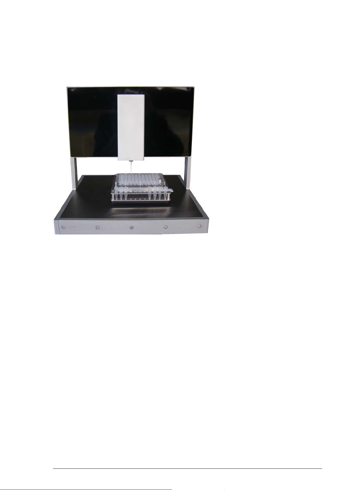
Roboinject
The well plate carrier, powered by linear motors, hovers smoothly and noise free on a cushion
of compressed air above the magnetic x/y table. The carrier operates at a resolution of 20 μm.
The complete system does not require maintenance other than occasional cleaning of the steel
plate. The well plate carrier can hold up to eight industry standard 0.5 ml reaction tubes serving
as sample reservoirs.
9
Page 14
Roboinject Manual
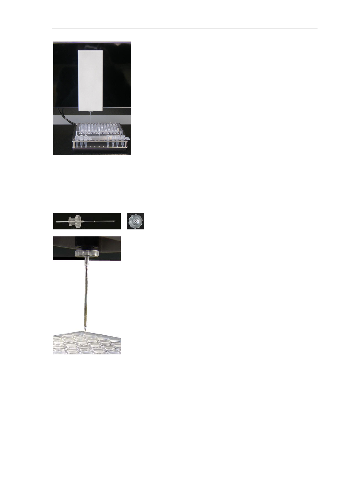
The vertically moving injector mount (z-axis), holding the injection device, is designed
specifically for the demand of high stability, speed and precision. It moves at a resolution
of 20 μm; position and speed are software controlled.
The injection device is composed of a linear motor driving a steel plunger which fits precisely
in the provided injection capillaries. The oil gap between the inner glass wall and the plunger
surface serves for a perfect leak tightness and makes additional gaskets dispensable.
Prepulled borosilicate glass micropipettes are provided by Multi Channel Systems MCS GmbH,
but custom injection needles may also be used. Mounting of injection capillaries is extremely fast
and simple by using luer fittings. There are no additional gaskets susceptible to leakage rendering
the injection device durable and maintenance free.
10
Page 15
Roboinject
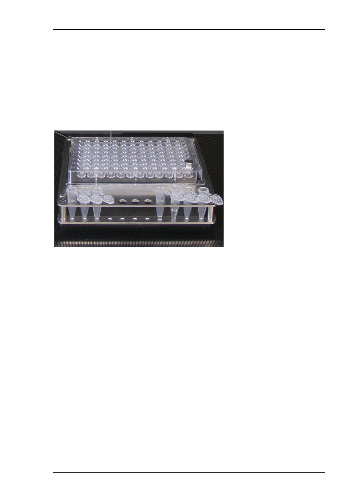
Injection and cultivation of Xenopus oocytes is performed using disposable standard 96 well
plates, which are commercially available from several providers. Please see chapter "Ordering
Information" in the Appendix. The oocytes are plated into the wells in a couple of minutes and
can be kept for several days. They quickly settle within the cone-shaped wells and adhere to the
well bottom after a few hours. The oocytes do not have to leave the plate anymore; you can easily
transfer the oocytes from the incubator to the Roboinject and back again.
A quick alignment process guarantees that the oocytes are injected precisely. The cDNA or mRNA
or other compounds to be injected are aspirated into the injection pipette by upward movement
of the plunger and then pushed into either the nucleus or the cytoplasm by downward movement
of the plunger.
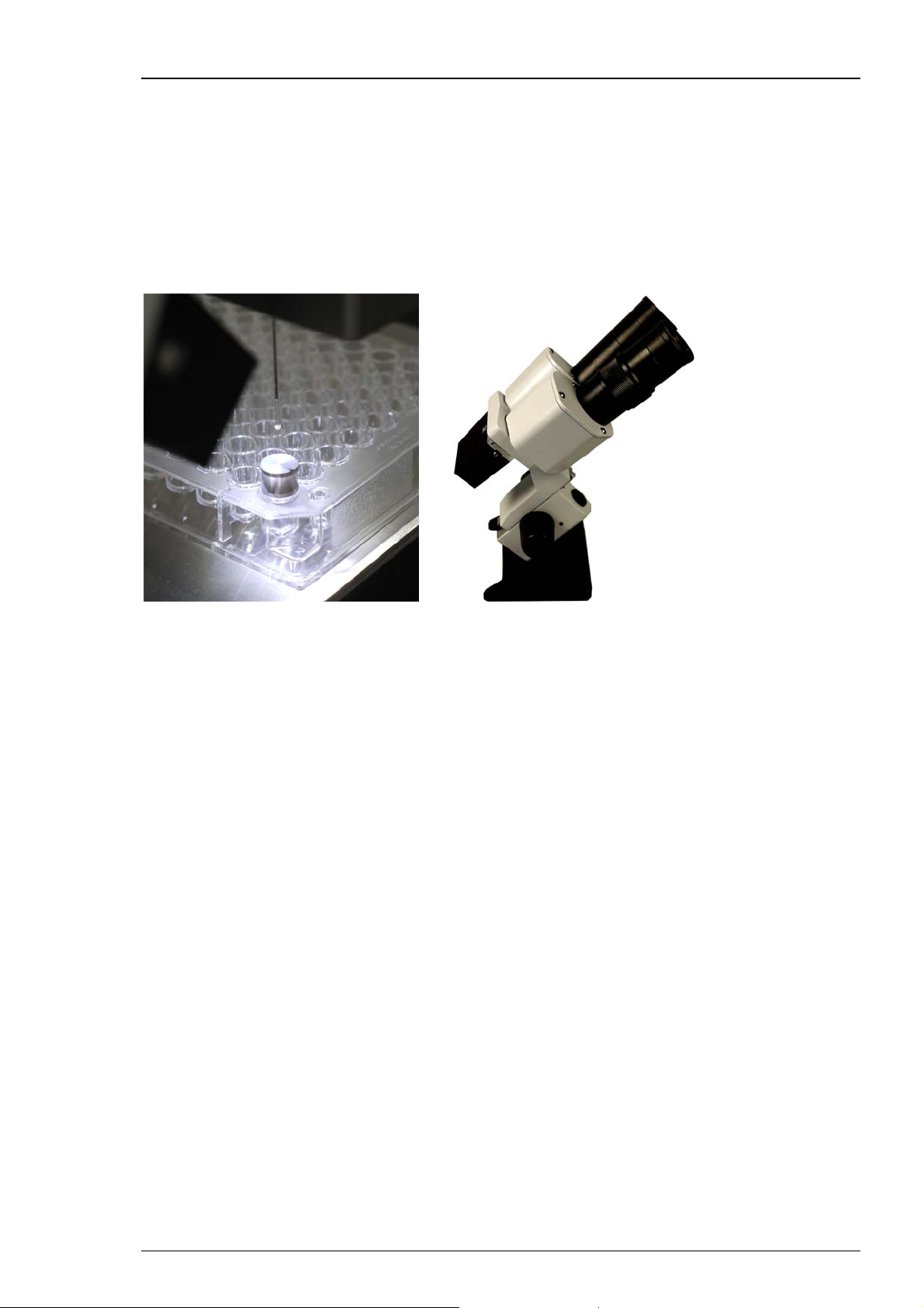
The provided microscope is mandatory for the alignment process. Place the microscope
in a position onto the x/y table which allows to focus on the alignment device plugged
in well H12 of the well plate. Please read chapter “Alignment” for detailed information.
11
Page 16
Roboinject Manual
3.3 Installing the Roboinject
Setting Up the Roboinject
1. Place the Roboinject on a rigid, stable, and vibration-free base in an air conditioned room.
2. Provide a power supply in the immediate vicinity of the installation site.
3. Provide a compressed air supply in the immediate vicinity of the installation site.
4. Place the computer and its accessories next to it.
Connecting the Roboinject
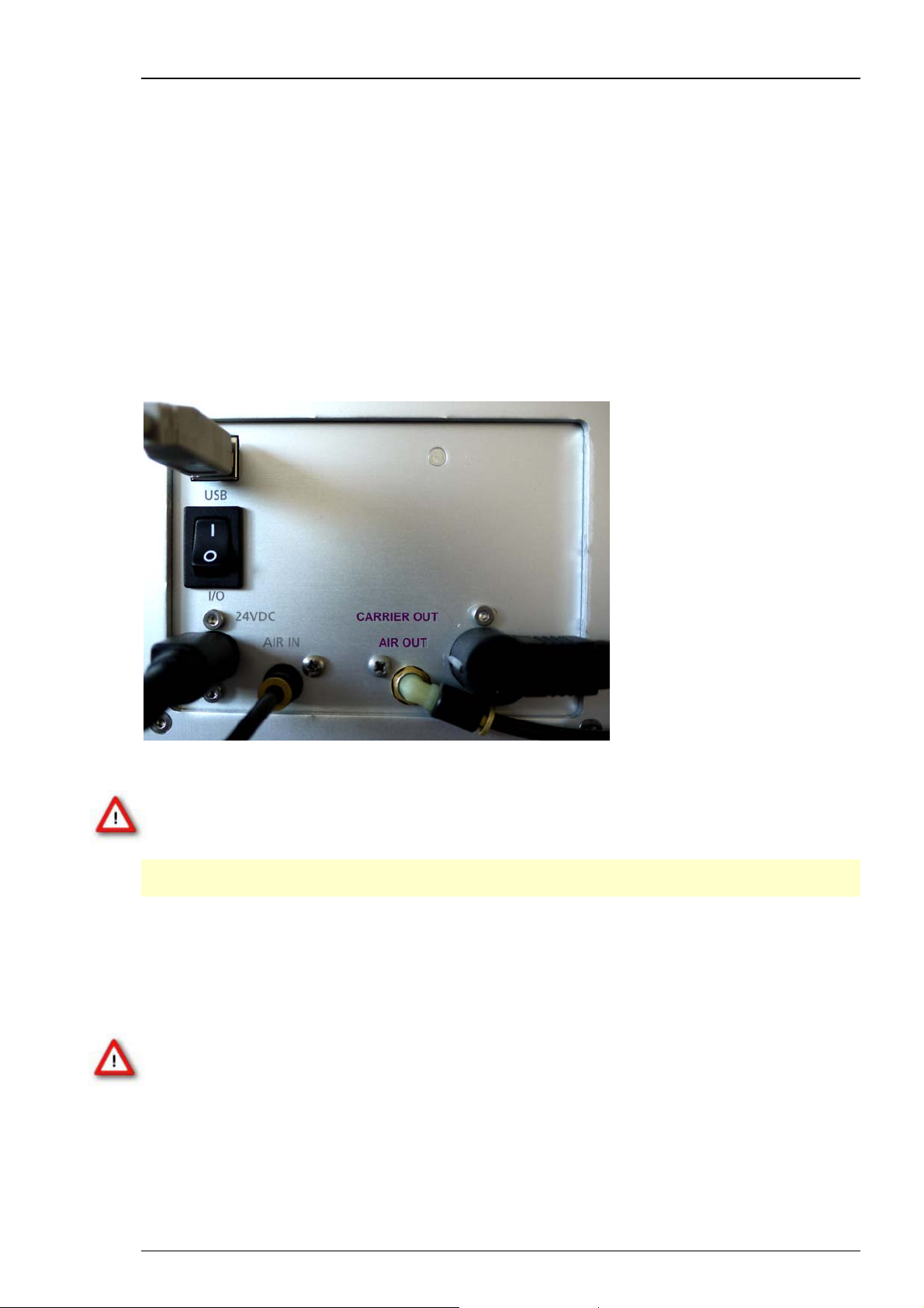
The following illustration shows the rear panel of the Roboinject.
Connect all cables as described below.
Warning: Carefully lay and secure the cords. Remember that someone could easily trip over
a loose cable.
Note: All electrical connections are clearly marked, and the plug coding prevents confusion.
The cords should be plugged in without the use of excessive force.
Connecting the carrier
Plug the carrier connector into the according socket located on the Roboinject's rear panel,
labelled with "CARRIER OUT".
Warning: Confusion of the compressed air's inlet and outlet may destroy the device.
Have a close look at the preceding picture of the Roboinject's rear panel and take care
to connect the lines properly. The air hose connecting the Roboinject with the well plate
carrier is close to the electrical connection between them.
12
Page 17
Roboinject
Connecting the Roboinject to the pressure line
1. Connect one end of the provided compressed air hose (ID 2.5 mm, OD 4 mm) to the water
separator.
2. Connect the other end to the compressed air inlet on the Roboinject's rear panel, labelled
with "AIR IN".
3. Connect the other provided compressed air hose (ID 4 mm, OD 6 mm) to the provided water
separator.
4. Make sure that the pressure line is closed. Connect the free end of the provided compressed
air hose (ID 4 mm, OD 6 mm) to the pressure line, labelled with "AIR OUT".
5. Open the pressure line and apply a pressure of 3 bar with the provided pressure regulator.
Warning: Make sure that the compressed air used fulfills all requirements for working with
the Roboinject. Otherwise, use of an improper compressed air could result in physical harm
to the hardware. Especially, check that the compressed air is absolutely free of water, oil,
and any particles. Refer to the chapter "Important Safety Advice" for more information.
Connecting the Roboinject to the computer
1. Connect the Roboinject by the provided USB cable, labelled with "USB".
2. Connect the Roboinject to the power line.
3. Finally, plug the power cord into the AC power line input, labelled with “24 VDC”.
4. Switch the Roboinject on or off via “I/O” toggle switch.
Warning: If the air cannot circulate freely around the external power supply, the device
may overheat. Do not shield the power supply by laying anything on top of it. Make sure
it is not exposed to direct sunlight.
13
Page 18

Roboinject Manual
3.4 Installing the Roboinject Software
System requirements
Software: One of the following Microsoft Windows ® operating systems is required:
Microsoft Windows 7, Vista or XP (English versions supported with the NT file system).
Other language versions may lead to software errors.
Hardware: An USB 2.0 High Speed serial bus must be provided for the communication
between the Roboinject and the computer. Additional 1 GB RAM working memory
is strongly recommended.
Recommended operating system settings
The following automatic services of the Windows operating system interfere with the data
storage on the hard disk and can lead to severe performance limits. These routines were
designed for use on office computers, but are not very useful for a data acquisition computer.
Turn off “Windows System Restore”.
Turn off automatic “Windows Update”.
Deselect “Windows Indexing Service” for all local disks.
Turn off “Optimize hard disk when idle” (automatic disk fragmentation).
It is also not recommended to run any applications in the background when using the Roboinject.
Remove all applications from the Autostart folder.
Please check the system requirements before you install the software. MCS cannot guarantee
that the software works properly if these requirements are not fulfilled.
Important: Please make sure that you have full control over your computer as an administrator.
Otherwise, it is possible that the installed software does not work properly.
Installing the Roboinject Software with computer connected
Power up the connected computer and wait until it is ready.
1. Double-click Setup.exe on the installation volume. The installation assistant will open
and guide you through the installation procedure.
2. Follow the instructions of the installation assistant. The Roboinject software and all necessary
drivers will be installed on your computer.
14
Page 19

3.5 Roboinject Software
Starting the Roboinject
Press the main switch on the back of the Roboinject for switching on the Roboinject.
The Roboinject is starting now. After a few seconds the Roboinject is ready for use.
Starting the Roboinject Software
You may use the computer and the software offline that is, the Roboinject is switched off or not
connected to the computer, to review already injected plates or define new injection protocols.
You can switch from offline to online mode, when the Roboinject is switched on later. However,
if you start the software to operate the Roboinject, the easiest way is to start the Roboinject first
and then start the software.
Each time you start the Roboinject software the well plate carrier and the injection mount will
automatically move to a reference point, that means to the "home" position. These movements
do not use any software command.
The factory preset default values have been extensively tested with RNA and DNA injection of
Xenopus oocytes and should work in most circumstances. Therefore, it is advisable to use the
default values for the first injections with Xenopus oocytes.
Roboinject
1. Double-click the Roboinject icon
- OR -
Select Roboinject from the "Start" menu to start the Roboinject software.
2. When you start the Roboinject software for the very first time, the file dialog box appears
for setting the directories for the plate files and template files. You can either accept the
predefined directories or select directories according to your personal preferences.
If the Roboinject is offline indicated by a red status lamp below the Roboinject logo,
switch the Roboinject on and wait until the status lamp turns green.
on the desktop.
15
Page 20
Roboinject Manual
The Roboinject main window opens.
16
Page 21

3.6 Main Menu
For maximum flexibility all relevant parameters for the injection can be changed by the user
via main menu.
Note: The preset default values have been extensively tested with RNA and DNA injection of
Xenopus oocytes and should work in most circumstances. Therefore, it is advisable to use the
default values for the first injections with Xenopus oocytes.
File
Roboinject
Menu for creating new files, opening existing files, and for saving them. Menu for opening
and saving templates, and for closing the program.
The option "Export to Roboocyte1" is a feature for exporting plates to the Roboocyte1 device
from Multi Channel Systems MCS GmbH.
Well plate files, created and saved with Roboinject software, can be transferred to the data base
of Roboocyte1 software. The corresponding well plates, injected with the Roboinject device can
be processed with the Roboocyte1 device. The feature is available only for owners of Roboocyte1
devices (Clamp Amplifier A and Clamp Amplifier B) and together with Roboinject software
version 1.1.0 which includes a firmware update. It is not possible to export plates to other devices.
17
Page 22
Roboinject Manual
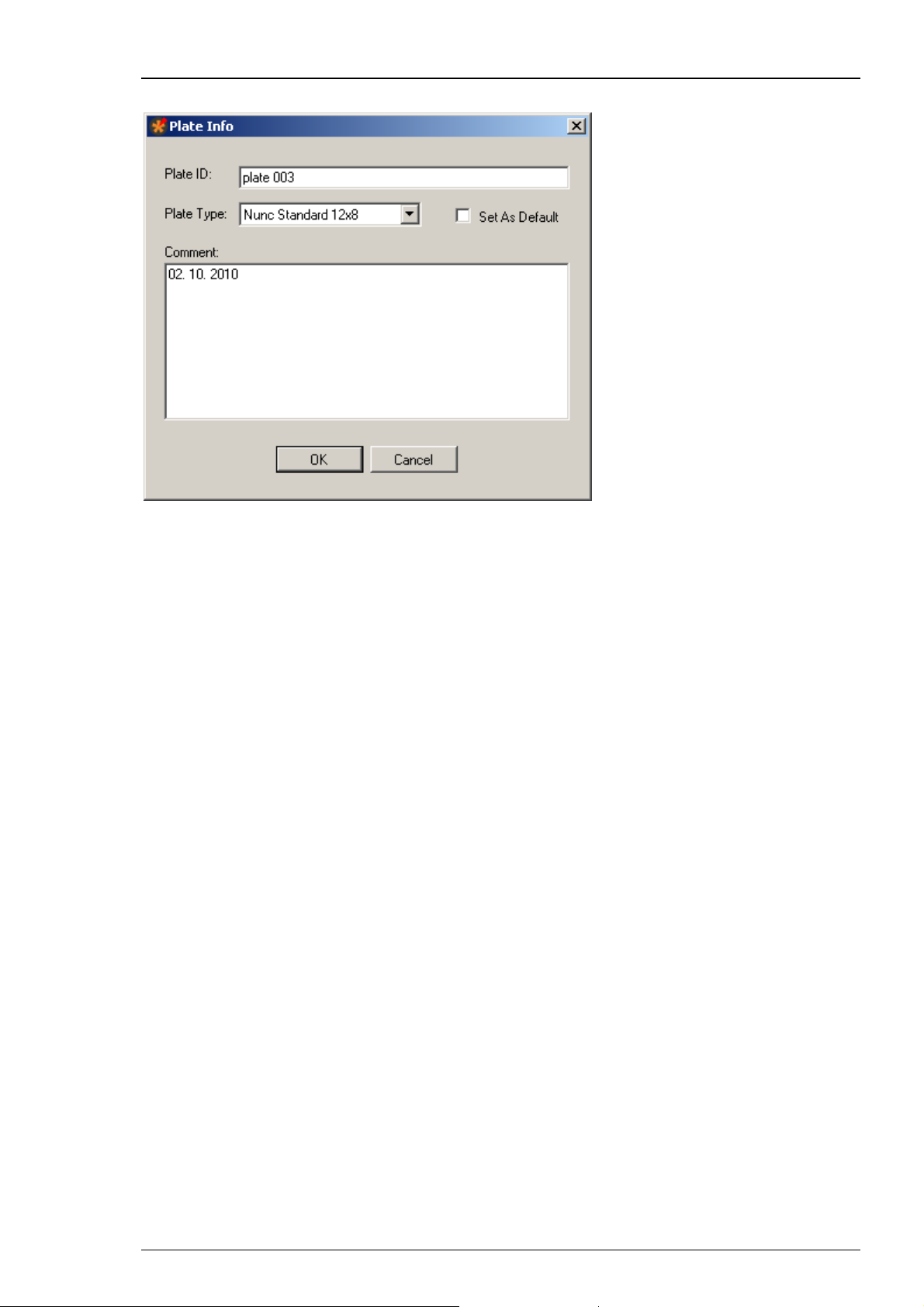
Click "New" in "File" menu. The following "Plate Info" dialog opens.
Please give an appropriate file name in "Plate ID". The type of the well plate can be defined
from the "Plate Type" drop down menu. If you want to set the selected plate type as default,
please enable the check box "Set As Default". You can type in notes concerning the actual
experiment into the "Comment" text box. All information will be stored in the plate info (*.rpf)
file, and displayed in the report sheet.
If you want that the plate ID is automatically counted up when creating a new file, please enable
the check box “Auto increment plate ID” in “General” tab of the “Options” dialog in main menu
“Settings”.
Click "OK" to enter additional dialogs, or to start the injection.
If you want to inject the same plate again or review previously injected cells, open the appropriate
well plate file.
18
Page 23
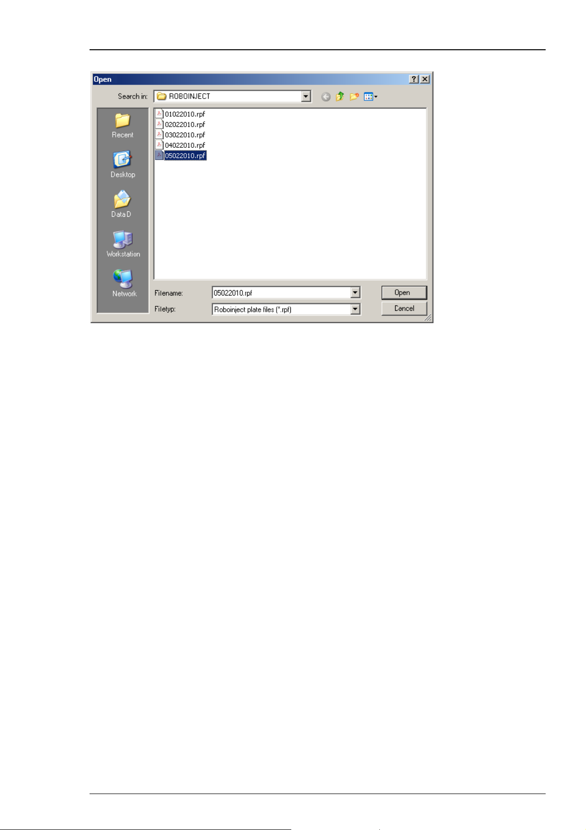
Click "Open" in "File" menu. The "Open" dialog box appears.
Roboinject
Browse your folders and select the Roboinject plate info file (*.rpf) you want to open.
Click "Open". The main window now shows the state of the already saved plate.
Click "Save" to save a Roboinject plate info (*.rpf) file. It will be stored in the selected
"Plate Info" directory.
Click "Save Template" and "Open Template" to open and save a template (*.rit) file.
It will be stored in the selected "Template" directory, respectively.
Click "Exit" to close the Roboinject software program.
19
Page 24
Roboinject Manual
Settings
Menu for setting options and for defining directories.
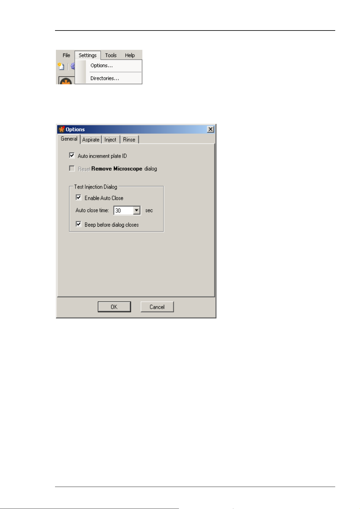
Click "Options" in main menu "Settings". The "Options" dialog has four tabs.
Click "General" tab.
The dialog allows general settings concerning two general software features,
and the "Test Injection Dialog" in particular.
Enable the check box "Auto increment plate ID", if you want that the plate ID
is automatically counted up when creating a new file.
Enable the check box "Reset / Remove Microscope dialog" if you want to see
the “Remove Microscope” dialog after alignment again.
The “Test Injection” dialog appears immediately before the injection run of each sample
if selected in the "Sample Information" dialog. This allows the user to execute a test
injection before starting the injection run or to stop the injection run completely.
With regard to the "Test Injection Dialog" you can select or deselect the two check boxes
"Enable Auto Close" and "Beep before dialog closes". Additionally you can choose
the time span for displaying the "Test Injection Dialog" from the drop down menu.
The "Auto close time" varies from 30 to 180 seconds.
20
Page 25
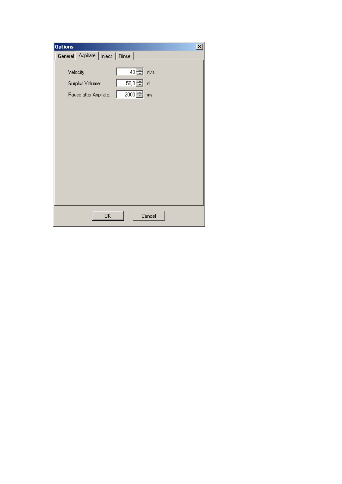
Click "Aspirate" tab.
Roboinject
This dialog allows to define the aspiration of compound from the reservoir tubes.
The parameters are the “Velocity” of aspiration in nl/s, the “Surplus Volume” in nl,
and the “Pause after Aspirate” in ms.
“Velocity”: The aspiration velocity for a given compound depends on its viscosity. Samples
with high viscosity should be aspirated slower than samples with low viscosity. This prevents
the accumulation of negative pressure inside of the injection needle leading to the formation
of air bubbles inside of the capillary.
“Surplus Volume”: In order to prevent the injection of minute volumes of mineral oil -
the needle was filled with first - with the last injection, you can define a "Surplus Volume".
The volume will be aspirated additionally to the injection volume, defined in the "Injection" tab.
Values of 50 nl are recommended.
"Pause after Aspirate": You can define a time period during which the injection needle stays
in the compound after aspirating the RNA, DNA or other compounds, before the injector mount
moves upward. This feature minimizes the risk of sucking air into the needle tip. A time span of
2000 ms is recommended.
21
Page 26
Roboinject Manual
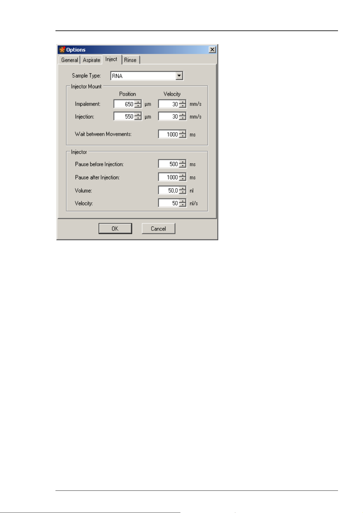
Click "Inject" tab.
The dialog allows to define parameters concerning the “Injector Mount” (z-axis) and the
“Injector” device itself. The settings are attributed to the different "Sample Types" such
as RNA, DNA or others.
“Sample Type”: Define the type of compound to which you want to assign the setting
parameters from the drop down menu.
“Injector Mount = z- Axis”:
You can separate the impalement process of the injection needle into an oocyte or another cell
in two phases. This is especially useful, for example, when working with "soft" oocytes. If the
first movement (for example, to 650 μm above well bottom) only pushes down the cell without
penetrating the vitelline layer and membrane, a second movement (for example, to 550 μm
above well bottom) will most likely lead to a successful impalement. Please see the picture.
Please define the parameters of the first step, called “Impalement Position”. Please note that
the value in micrometer refers to the distance between the tip of the needle and the well bottom.
Define the “Velocity” of impalement in mm/s. The default value of 30 mm/s was intensively
tested with oocytes and will work in most of the cases.
Please define the parameters of the second step, called “Injection Position”. Define the position
of the injection in μm from the up-down control. Please note that the value in micrometer refers
to the distance between the tip of the needle and the well bottom in relation to the bottom of
the well. Define the “Velocity” of injection in mm/s. Again, the default of 30 mm/s will work with
most oocytes.
22
Page 27
Roboinject
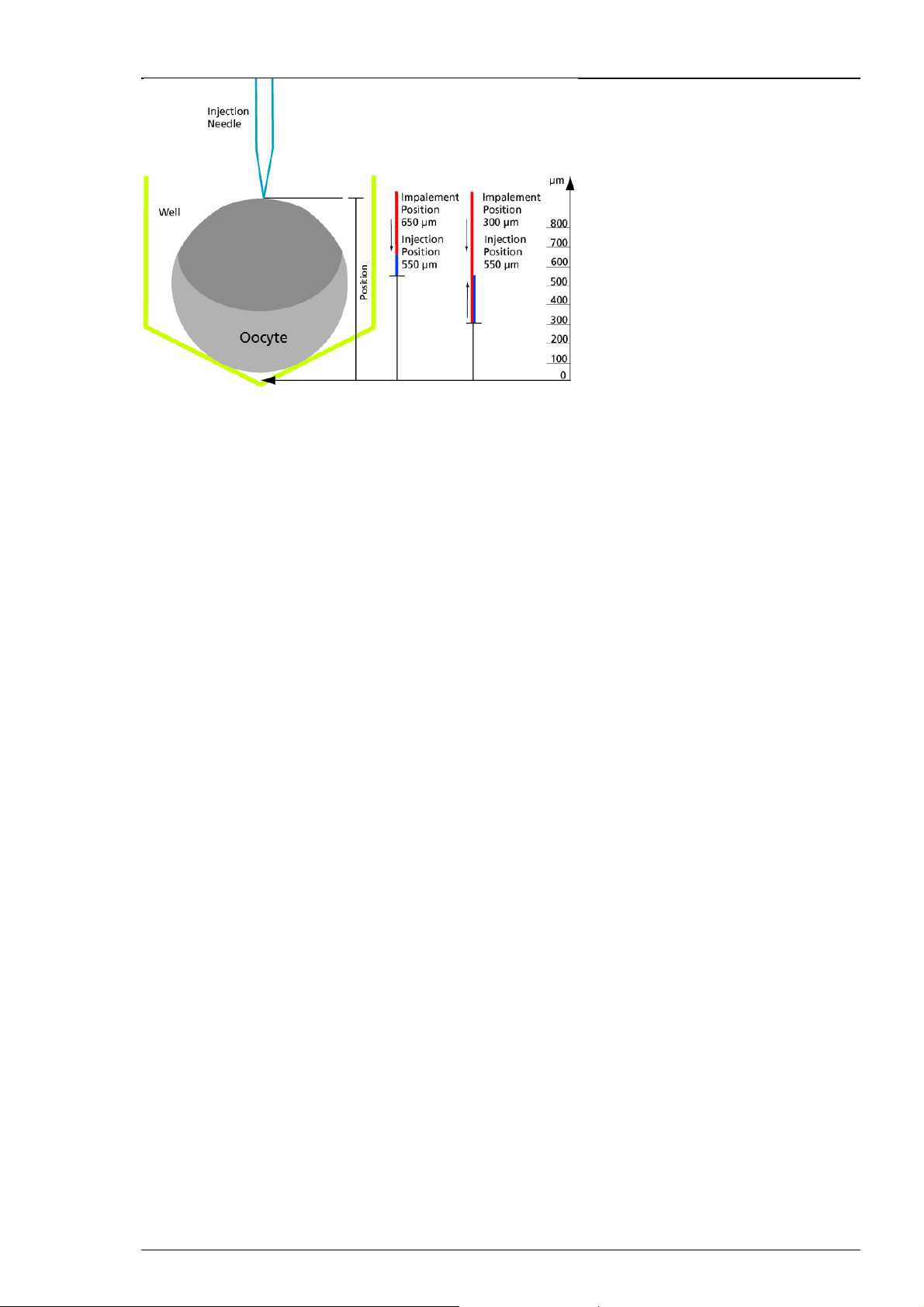
Example on the picture: The bottom of the well is value zero, the reference value. If you define,
for example an impalement position of 650 μm, the injector mount will move down until its
position is 650 μm above the bottom of the well. If you additionally define an injection position
of 550 μm, the injector mount will move down again until its position is 550 μm above the bottom
of the well.
If you define, for example an impalement position of 300 μm, the injector mount will move down
until its position is 300 μm above the bottom of the well. If you additionally define an injection
position of 550 μm, the injector mount will move up until its position is 550 μm above the bottom
of the well.
The “Wait between Movements” in ms as well as the "Pauses before and after Injection"
can be adjusted to user preferences.
“Injector”
The injection interval is terminated by the time frame before injection "Pause before
Injection", and the time frame after injection "Pause after Injection", both measured in ms.
The default values for the wait times before and after injection (500 ms and 2000 ms, respectively)
have been tested with oocytes and RNA injections.
You have to define the injection “Volume” in nl, and the “Velocity” in nl/s from the up-down
controls. The respective default values (50 nl and 70 nl/s) have been tested with oocytes and
should work in most cases.
23
Page 28
Roboinject Manual
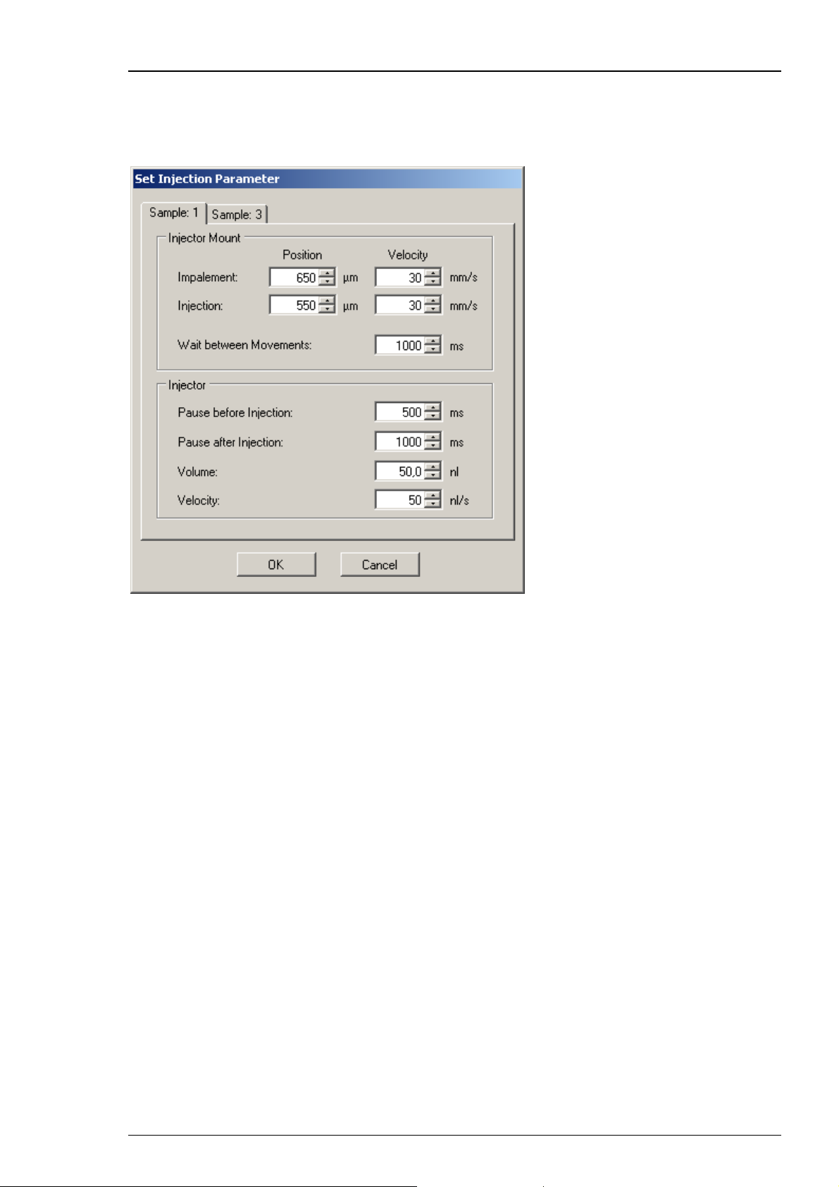
Adjusting the Injection Parameters for each Well separate
It is possible to adjust the settings for the injection for each single well separate. Click with
the right mouse button onto a well in the virtual well plate, and the following dialog appears.
Now you can adjust the injection parameters for this specific well and for each sample separate.
If the oocyte in the specific well should be injected with different samples, you can adjust
the injection parameters for each sample separately. Please click the "Sample" tabs.
24
Page 29

Click "Rinse" tab.
Roboinject
Rinsing the injection needle between the injection of different samples is mandatory for
preventing cross-contamination. In principal, you can reuse an injection needle as long as
it is not clogged or broken. Nevertheless, MCS does not recommend to reuse the needle
longer than one day after the last injection.
Define the number of "Repeats", the "Rinse Volume" in nl, and the "Velocity" in nl/s
from the up-down controls to avoid contamination when working with different compounds.
Volumes of 1000 nl and three repeats guarantee the absolute purity for each injected sample.
Click "Directories" in main menu "Settings". The "Set Directories" dialog opens.
Templates: Please browse through your folders, and define the directory you want to store
your template files with the extension "*.nit".
Plate Info: Please browse through your folders, and define the directory you want to store
your plate info files with the extension "*.rpf".
The "Log" file with the extension "*.log" is a file you can save by users command from
the "Log File" window. Please browse through your folders, and define the directory you
want to store the log files.
25
Page 30

Roboinject Manual
Tools
Menu for manual mode and for creating a report sheet. The option "Set Plate to Manually
Injected" offers the possibility to document information about a well plate, loaded with manually
injected oocytes which will be processed with the Roboocyte1 device. Please see below.
About software controlled manual manipulation of the Roboinject, please read the next chapter
"Toolbar" "Open Manual Mode Dialog".
Click "Show Report".
The report sheet displays all important information about the selected well plate: Plate ID,
plate file destination, report date, plate date, plate type and notes written in the comment.
When injection run has finished you find additionally the definition of the samples,
and the well plate. The log file is displayed.
26
Page 31

Roboinject
Click "Set Plate to Manually Injected".
When you are using the Roboocyte1 device from Multi Channel System MCS GmbH and you
decide to inject manually, or if you performed manual injection with Roboinject for other reasons,
you can define the oocytes of a well plate as "injected" with this function.
Click "File" menu “New” to create a new plate. Fill in the respective information about the well
plate, created and injected in Roboocyte1.
Define the samples which were used for injection in Roboocyte1 device.
Define the respective wells in the plate view.
Right-click on each well to document the information about the injection of the cells in the “Set
Injection Parameter” dialog. After that click the option “Set Plate to Manually Injected”, and the
wells - already injected in Roboocyte1 - are marked as injected with black arrows. After doing so,
please save the file. Then you can create and print a report about a well plate, which can not be
created in Roboocyte1 software. The feature is available only for owners of Roboocyte1 devices
(Clamp Amplifier A and Clamp Amplifier B) together with Roboinject software version 1.1.0 which
includes a firmware update.
27
Page 32

Roboinject Manual
Help
The menu offers the use of the Roboinject online help, and shows the "About Roboinject" dialog.
Click “Roboinject Help” to start the online help.
Click "About".
The dialog displays the actual used version of Roboinject software, and hardware information.
Note: Please keep in mind that these information are essential in case of support!
28
Page 33

3.7 Toolbar
Roboinject
Click the "New File" icon
The "Plate Info" dialog opens. Please read the description in chapter "File" of the main menu.
.
Click the "Open Manual Mode Dialog" icon
.
29
Page 34

Roboinject Manual
The "Manual Mode" dialog opens. The dialog is divided in five sections: Global, Plate Carrier,
Air Pressure, Injector Mount and Injector. That means, you are able to influence each part of the
device manually via software controls. The commands inside the sections refer to the plate carrier,
the injector mount (= z-axis) and the injector (= plunger) only. The "General" section refers to the
complete device. The "Air Pressure" check is for measuring the air pressure in the pressure line of
the Roboinject device.
Warning: The "Manual Mode" gives you the chance to test the Roboinject device and all its
parts separately. Since all kind of movements are allowed, you can easily destroy almost any
part of the Roboinject by executing movements at the wrong time. Please always doublecheck before executing any command, whether this command could be harmful to the
Roboinject.
Examples:
Moving the carrier when the injection needle is inside of an well will destroy the needle.
Moving the z-axis to "Tube" position when the carrier is at any well position will destroy
the needle and bend the plunger.
Moving the carrier when the z-axis is at "Tube" position will destroy the injector device
and bend the plunger.
Please handle with great care!
Global Section
Click "Reference" to perform reference movements of carrier, injector mount (z-axis),
and injection plunger.
Click "Coarse Position" to initialize the manual carrier and z-axis alignment after installation of
the injection needle. The z-axis will move to a position 3 mm above the last z-alignment position,
and the carrier will move to the last x/y-alignment position. (If the last alignment was right,
this will be exactly below the position of the injection needle).
Click "Change Plate" for changing the well plate. The carrier will move to a position at which
you can easily access the well plate or the reservoir reaction tubes.
Click "Home" for moving the carrier and the z-axis in home position (X = 0, Y = 0, Z = 0).
Click "Set Alignment" for setting the actual position of carrier and z-axis at the alignment
position. Before doing so, please insert the alignment tool in well H12 when using a 96 well plate.
Click "Change Needle" for installing, changing or removing the injection needle in the injection
mount. The carrier will move to its home position (or stay there), and the z-axis will move down
to allow you an easy access to the luer connector for the injection needle.
30
Page 35

Plate Carrier Section
Click "Reference". The carrier performs its reference movement in x/y direction.
If the carrier does not move, please check all cable connections.
Roboinject
Warning: Perform the alignment procedure before using any of the following commands.
Please double-check whether the z-axis is in "Home" position whenever carrier movements
are elicited. Otherwise there is the risk of severe damage to the injector.
Click "Home" for moving the carrier in home position. The home position is defined as the
backmost right corner of the x/y table when looking on the front panel of the Roboinject
(X = 0, Y= 0).
Select a "Well" from the drop down menu. Select well A1, for example, and click "Well".
The carrier will move until well A1 is exactly underneath the injector axis.
Select a "Tube" from the drop down menu. Select tube 1, for example, and click "Tube".
The carrier will move until tube 1 is exactly underneath the injector axis.
Select "Rinse 1", "Rinse 2" or "Waste". This will move the carrier to the tubes serving as rinse
and waste station, respectively.
Click "Air Cushion", and select "Slow" or "Fast" movement. Use the arrow buttons
to move the carrier stepwise in 30 μm steps (slow) or continuously (fast) to any desired position.
The X and Y values show the actual position relative to the home position (X = 0, Y = 0).
The air cushion pressure is only present when the carrier receives a movement command from the
software. Therefore, never touch the carrier or try to move the carrier manually when it performs
software controlled movements. There is only one exception during alignment of the carrier to
the grid of the table manually. For this purpose, switch on the air cushion pressure by clicking "Air
Cushion" in “Manual Mode”. In this mode it is possible to move the carrier safely by hand as long
as the "Air Cushion" button is active. Please see chapter "Alignment of the Well Plate Carrier".
Warning: Remove the injection needle before manually moving the carrier. Otherwise there
is the risk of severe injury and damage of the injector.
31
Page 36

Roboinject Manual
Air Pressure Section
Check the air pressure. It should be set to a minimum value of 3000 hPA,
and should never exceed a value of 4 bar.
Injector Mount = z-Axis Section
Click "Reference". The z-axis will perform its reference movement and will stop in home position.
The depicted Z value is 0 μm.
Click "Home" to move the z-axis into home position. The home position for the z-axis is defined
as the position when the injection device is at its topmost position. The depicted Z value is 0 μm.
Click "Tube". The z-axis moves to a position from where a sample can be taken up from one of
the reservoir tubes.
Warning: Never try to move the z-axis to any tube position before moving the carrier
to the respective tube. Otherwise there is the risk of severe damage of the injector.
Click "Impalement". Select the "Depth" of impalement from the drop down menu.
Select "Rinse 1", "Rinse 2" or "Waste". The actual position of the z-axis will be displayed
in "Z = x μm".
Use the arrow buttons to move the z-axis stepwise in 20 μm "Slow" or 200 μm "Fast" steps
up and down. The "Z" value shows the actual position of the z-axis in μm relative to the home
position (Z = 0).
32
Page 37

Roboinject
Injector = Plunger Section
Click "Reference". The plunger will perform its reference movement and will stop in home
position.
Click "Home" to move the injection plunger inside the z-axis into home position. The home
position is defined as the topmost position.
Click "Replace" to start the needle installation or needle changing.
Click "Empty" to move the injector plunger continuously from the topmost position into the
injection needle to extrude the oil filling of a new injection needle.
Click "Aspirate" to move the injector plunger upwards for aspirating the volume in nl selected
from the up-down control beside the button. Be sure to immerse the tip of the needle into the
medium you want to aspirate to avoid the suction of air into the needle.
Note: You cannot aspirate more "volume" than it has been ejected before by the command
"Empty".
Click "Inject" to move the plunger stepwise from top to bottom, for injecting the volumes
selected from the up-down control beside. It is possible to inject volumes from 1 to 100 nl.
Changing the Injection Needle
Click on the
icon to open the "Manual Mode" dialog.
Use the injector section to test the functionality of the injector with installed injection needle to
test the injector under more realistic conditions or to do injections manually. Click "Home" and
wait until the plunger arrived at its topmost home position. Click "Replace" in “Injector Section”
of “Manual Mode” if there is an used needle installed, and remove it carefully. Be sure not to
bend the plunger wire.
Fill a fresh injection needle completely and air-bubble free with mineral oil. Install the needle by
inserting the plunger wire end slowly into the capillary. Lock the luer connector tightly but not
with excessive force.
33
Page 38

Roboinject Manual
Alignment of the Well Plate Carrier
The well plate carrier hovers over the magnetic x/y table. For a smooth and proper movement,
it is crucial that the table is kept dry and clean, and the carrier is properly aligned on the table.
Clean the x/y table with a soft tissue and pure alcohol.
Click on the
icon to open the "Manual Mode" dialog.
Activate the air cushion by clicking on the "Air Cushion" button. Now it is possible to move
the carrier carefully by hand. Switch the Roboinject off for cleaning the x/y table and the carrier.
After cleaning, switch the Roboinject on. Activate the air cushion again to align the carrier
precisely to the grid on the x/y table by hand. The air cushion will be automatically deactivated
when you close the "Manual Mode" dialog.
Important: A manual movement of the carrier is possible only if the Roboinject is switched
on and the air cushion is present. Please make sure that the compressed air pressure is sufficient
(minimum 3 bar).
Warning: Do not use aqueous solutions and / or cleaning agents for cleaning the magnetic
x/y table. Otherwise, the carrier and / or the x/y table can be damaged. Please make always
sure that the carrier is aligned to the grid of the table. Otherwise, a correct movement of
the carrier is not possible.
Click "Show Report" icon
.
Please see chapter "Tools", "Show Report" of the main menu.
Click "Clear Plate" icon
.
The "Clear Plate" button sets back all wells which are already assigned to a sample
to the original, non-selected status. The deselected (crossed out) wells will remain.
Click "Void Well" icon
.
The icon is for selecting or deselecting wells in the virtual well plate. If you activate the button
"Void Well" you can select and deselect single wells or rows and columns. The deselected wells
are crossed out, and will not be injected.
34
Page 39

3.8 Control View
Roboinject
The "Control View" on the right side of the main window of the Roboinject software is divided
into two smaller windows: "Injection" and "Log" file.
In the "Injection" window the status LED indicates the status of the device. Green color indicates
a valid connection between Roboinject and computer, red color indicates no connection.
The "Start" and "Break" buttons start and interrupt the injection process. The status bar below
the buttons displays the injection proceeding during the injection run.
In the "Log" file window the injection process is documented.
35
Page 40

Roboinject Manual
"Injection" Window
After completing the definition of the injection protocol the "Start Injection Wizard" proceeds
with the final preparations for the injection.
Via "Start" and "Break" buttons you start and stop the injection manually. The status bar under
the buttons will show the processing of the injection.
Click the "Start" button. The "Preparation" dialog of the "Start Injection Wizard" appears.
Air pressure: Please check the air pressure, the minimum has to be 3 bar = 3000 hPa.
Check the connection status: A green LED indicates a sufficient air pressure.
Plate Carrier: Click "Change Plate". This command will move the carrier to an easily accessible
position. Please remove the old well plate from the carrier if necessary, Take a well plate from
the type you specified in the "Plate Info" dialog box. Place the plate onto the carrier and press
it against the springs in the lower middle and lower right corner of the carrier. Then put the rest
of the plate down onto the carrier. The well plate position is correct when there is no play
between the well plate bottom and the carrier surface at all edges and when the well plate
has full contact to the left and upper side of the carrier holding frame.
Place the reservoir tubes according to their appearance in the virtual well plate in the respective
mounting holes. Do not use excessive force. Also place the rinse tubes and the waste tube at their
designated positions.
Click "Home" for moving the well plate carrier into the home position.
Injector Mount: Please mount an injection needle. Click "Change Needle". Enable the check box
"Reset Needle Coarse Position" to initialize the manual z-axis alignment after installation of
the injection needle, if the needle length has changed.
Put the alignment device (with crosshairs) into well H12. Please read chapter “Alignment”.
36
Page 41

Click "Next". The "Alignment" dialog of the "Start Injection Wizard" appears.
Roboinject
Plate Carrier: It is possible to move the plate carrier stepwise with the arrow buttons
in x- and y- direction on the table. The actual position of the carrier in relation to the home
position (X = 0 μm, Y = 0 μm) is displayed.
Use the arrow buttons to move the carrier stepwise in 30 μm steps (slow) or continuously (fast)
to any desired position. The X and Y values show the actual position relative to the home position
(X = 0, Y = 0).
Injector Mount: It is possible to move the injector mount stepwise with the arrow buttons
in z- direction on the plunger. The actual position of the carrier in relation to the home position
(Z = 0 μm) is displayed.
After proper alignment in x, y, and z- direction click "Finish".
The "Remove Microscope" dialog appears.
Please enable the check box if you do not want to see this dialog again. You can display
the dialog again when selecting the check box "Reset Remove Microscope dialog"
in the "General" tab of the options dialog.
Click "OK" and a sequence of movements are performed. First, the carrier moves to "waste"
position and the oil is extruded into the waste container. Then, the carrier moves to the first
defined sample tube and the necessary volume is taken up. Finally, the test injection dialog opens
if "Test Injection" was selected in the "Sample Information" dialog of the respective sample.
37
Page 42

Roboinject Manual
The "Test Injection" dialog appears immediately before starting the injection process
of the selected sample.
This dialog gives the user the possibility to check the transmissibility of the tip opening of the
injection needle. The defined sample volume will be injected into air. Before doing so, please
place the microscope on the x/y table in a way that you can clearly see the needle tip.
Multi Channel Systems MCS GmbH recommends up to two test injections for checking the
transmissibility of the tip opening. The additional volume for two test injections is aspirated
automatically in addition to the injection volume necessary for all injections of the respective
compound. The default test injection volume is half of the injection volume. If you have defined
different injection volumes for a respective compound, it is half of the largest injection volume.
If you do more than two test injections, the missing volume is automatically taken up during
the injection process.
Click the button "Inject" to perform the test injection the volume of which is displayed
in the up-down control window.
The "Sample" window displays important sample parameters. In the "Auto close" window
the time in seconds is counted down before this dialog is automatically closed.
Click "Continue" to start the injection process.
Click "Halt Time" if you need more time, for example, to check the tip opening by doing
test injections.
Click "Break" to stop the test injection and the general injection process, for example,
if the injection needle is broken or clogged.
The "Injection Halt" dialog appears.
38
Page 43

To control the ongoing injection process you can choose between three possibilities:
Click "Continue" to continue with injection process.
Click "Cancel" to stop the injection process. The carrier and the injection mount will
automatically move to home position.
Click "Stop" to stop the injection process without any movement of carrier or z-axis.
This is useful in case of severe malfunctions which could possibly lead to damages
if further movements would be performed.
After a successful injection process the Roboinject software displays
the "Injection Finished" dialog.
Roboinject
Click "OK" to continue with the same well plate, or remove the plate and click "OK".
"Log File" Window
The log file is displayed in the "Log File" window. The "Log" file documents the injection
process. To save the log file, click the "Save Log"
"*.log". To delete the log file, please click the icon "Clear Log"
icon. The log file has the extension
.. If you save the log file,
the "Save As" dialog will open. Please browse through your folders, and define the directory
you want to store the log file.
39
Page 44

Roboinject Manual
3.9 Tube View
In the "Tube View" you control the definition and selection of the samples. You can use
the eight reservoir tubes for eight different samples.
Click onto the symbol
The "Sample Information" dialog opens.
of a "Edit Sample" icon.
This dialog allows the definition of the respective injection samples inside of the 0.5 ml
micro reaction tubes.
Note: The sequence of injection is always from left sample (No 1) to right sample (No 8).
Please keep this in mind if the injection sequence of samples is of importance for you.
Enter an ID and / or a name which univocally identifies your sample in the "ID" and "Name"
window.
Select the type of sample RNA, DNA or Other in "Sample Type", and its "Concentration".
Important: The minimal volume which always has to remain in the tube reservoir is 1 μl.
For example, if you need 4 μl sample volume for your injection run, please make sure that
you start with at least 5 μl. This is because the injection needle keeps always a safe distance
to the tube bottom to avoid uptake of contaminants and clogging.
Enable the check box "Test Injection". The "Test Injection" dialog will appear before
the injection process of a sample is started. Please see chapter "Test Injection" dialog.
Type notes concerning the actual experiment into the "Comment" text box, for example,
the type of the sample when selecting "Others". The comments are saved in the "Plate Info"
file and shown in the report sheet.
40
Page 45

Roboinject
Click the "Set Injection" button for setting injection parameters for that sample. Ignore the
button for keeping the default settings.
Click "OK" to complete the settings for this sample. Click "Clear" if you want to restart with
default values, and "Cancel" if you want to go back to the main window without changes.
Repeat the settings in "Sample Information" of other tubes until all samples you want to inject
are defined.
Note: The sequence of injection is always from left sample (No 1) to right sample (No 8). Please
keep this in mind if the injection sequence of samples is important for your injection process.
Click "Set Injection". The "Set Injection" dialog opens. The parameters are also available
in the "Inject" tab of the "Option" dialog in main menu "Settings". Please read chapter
"Inject" tab of the "Options" dialog in "Settings" menu.
After finishing the settings in the “Sample Information” dialog the tube icons appear colored,
according to their content for a good discrimination between the compounds.
41
Page 46

Roboinject Manual
3.10 Well Plate View
This prominent "Well Plate View" shows a 96 well plate. When using a 384 well plate,
this view is automatically adapted.
Click the "Void Well" icon
well. To select or deselect complete rows or columns, click onto a letter on the left side to mark
a horizontal row, or onto a digit on top to mark a column. Deselected wells are crossed out,
and will not be injected. The well H12 is deselected by default. It is used for the alignment tool,
please read chapter "Alignment" for more information.
. To select or deselect a single well, please click onto the respective
42
Page 47

Roboinject
Click the "Clear Plate" icon to set back all wells to the original, non-selected status.
The deselected (crossed out) wells will remain.
43
Page 48

Roboinject Manual
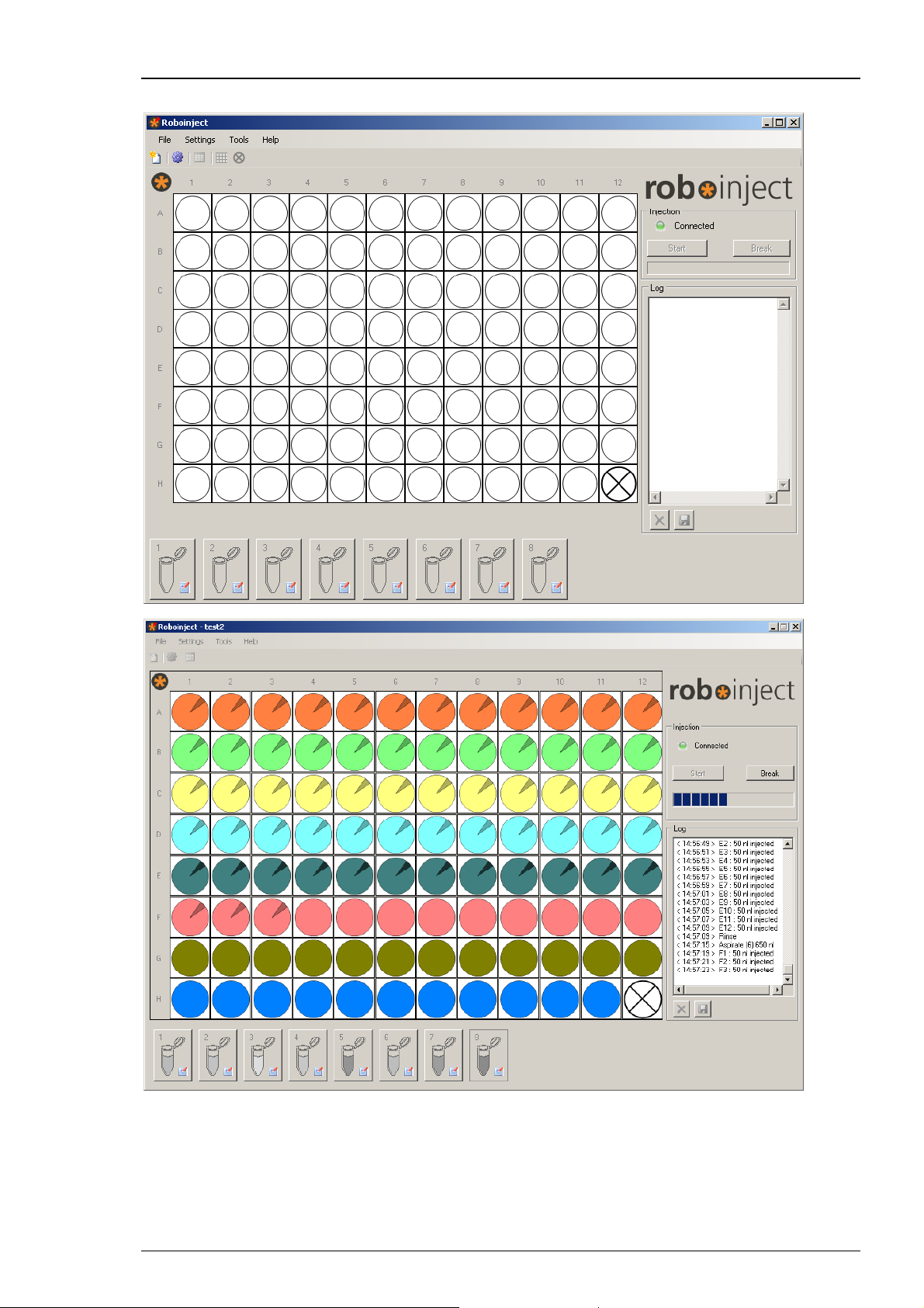
Defining the Samples
After setting up the "Sample Information” dialog, the samples of the tubes are fixed. To define
which well should be injected with which sample, please click onto the tube icon first, and then
onto the well icon. The color of the well will immediately change into the symbol color of the
sample of the selected tube. Choose another tube to assign one or several wells to that tube
sample respectively. It is possible to assign any well to any sample. Use the letters and digits
to correlate horizontal rows and vertical columns to the samples. Use the Roboinject icon
to select and deselect the sample of the complete well plate.
44
Page 49

Roboinject
Defining the Number of Injections into a single Oocyte
In some experiments it is necessary to inject more than one compound into a single oocyte.
The Roboinject program gives the possibility for up to four injections into the same oocyte.
To define the well for several injections, please click onto the tube icon first, and after that
onto the well. The color of the well will immediately change into the symbolic color of the
sample of the selected tube.
Select a second tube icon, and click onto the same well again. One half of the color of the well
will immediately change into the color of the second sample.
Select a third tube icon, and click onto the same well again. One third of the color of the well
will immediately change into the color of the third sample. Select a fourth tube icon, and click
onto the same well again. One quarter of the color of the well will immediately change into
the color of the fourth sample.
Click "Clear Plate" to set back all wells to the origin, non-colored status. The deselected
(crossed out) wells will remain. After successful injection the wells (or sections of the well)
will be marked with an arrow.
45
Page 50

Page 51

4 Injection
4.1 About Injection with the Roboinject
Manual injection is often a limiting factor in high-throughput screens. The Roboinject injects
Xenopus oocytes and other large cells or small embryos in a fully automated way.
For example, injection and cultivation of Xenopus oocytes are performed using disposable
standard 96 well plates, which are commercially available from several providers. The oocytes are
plated into the wells in a couple of minutes and can be kept there for several days. They quickly
settle within the cone-shaped wells and adhere to the well bottom after a few hours. The oocytes
do not have to leave the plate anymore; you can easily transfer the oocytes from the incubator to
the Roboinject and back again. For other cells or organisms custom-designed well plates can be
easily adapted.
The cDNA, mRNA or compound to be injected is automatically taken up into the injection needle
and then pushed into either the nucleus or the cytoplasm by the positive displacement method.
Using positive displacement has the advantage that the injected volume is always as pre-selected.
Importantly, it is independent of the viscosity of the samples or the opening diameter of the
injection needle. Another advantage of positive displacement based injectors when compared
to air-pressure driven system is, that there is no need of tedious volume calibrations.
The overall expression rate you can achieve with the Roboinject is by no means worse than success
rate with manual RNA injection of Xenopus oocytes and can reach close to 100 percent. Of course,
the success rate depends on the receptor type and oocyte performance.
47
Page 52

Roboinject Manual
4.2 Strategies for a Successful Injection
Multi Channel Systems provides injection pipettes with an inner diameter exactly matching the
plunger wire. The provided injection pipettes are glued to luer-fittings and therefore ready to use.
If you nevertheless decide to fabricate your own injection pipettes you should keep in mind that
you can only use the capillaries listed in the chapter "Ordering Information" in the Appendix.
Other capillaries will not work properly.
The Roboinject software allows to define the impalement and injection position for each sample
separately during the well selection process. The "Impalement Position" and the "Injection
Position" in the main "Set Injection" window denotes the distance of the needle tip to the well
bottom (zero value). This means, for example, that for an oocyte with a diameter of 1.2 mm an
impalement or injection position of 650 μm would correspond to an oocyte impalement depth
of 550 μm (1200 μm - 650 μm = 550) Please read chapter "Inject" tab of "Option" dialog in
"Settings" menu.
Changing and loading the injection needle
Click
or install a new needle. "Change Needle" will move the plunger and carrier in home position
and move the z-axis a bit down for better access to the luer connector for the needle.
Use a fine pipette tip, for example, a microloader tip filled with mineral oil. Insert the fine tip into
the injection needle as close as possible to the needle tip. Fill the injection needle completely and
air-bubble free with oil. The remaining air in the tip region will be cleared automatically later on.
Insert the plunger wire carefully into the needle end, move it slowly up and close the luer lock.
Part of the oil will drop out of the needle tip. Remove it with a soft tissue from the table.
Be careful not to break the glass capillary.
to start the “Manual Mode” dialog. Use the "Change Needle" command to change
48
Page 53

Injection
Xenopus oocytes
The impalement and injection distances for cDNA are preset to 300 μm and 550 μm, respectively.
(from the bottom of the well = 0 value).
These distances have been shown as the optimum values for DNA injection. The overall expression
rate you can achieve by this method is 80 percent of the oocytes. You can define your own
impalement and injection depth, but MCS recommends using the default values in order to
achieve the best expression rate.
You may wonder why the injection needle is placed so deeply for cDNA injections while the
nucleus is known to be located near the animal pole. As it seems, the nucleus is pressed down
by the injection needle until the pressure is sufficient for the needle to penetrate the membrane
of the nucleus.
Messenger RNA is injected into the cytoplasm. Generally, it is not important where in the
cytoplasm the RNA is released. The default impalement and injection distances for mRNA
are 650 μm and 550 μm, respectively. These are safe values even for smaller oocytes.
Running a test for nuclear injection with a dye
To demonstrate the precision of the injection and to practice the general handling, you may
consider running a test injection with the dye "Trypan Blue", which stains proteins unspecifically,
before you start to inject your constructs. Injected oocytes are then torn open with forceps, thus
releasing the complete, stained nucleus.
1. Dissolve Trypan Blue in distilled water. The solution should appear bright blue.
2. Remove any particles with a 0.22 μm syringe filter or something similar.
Continue with the next chapter "Preparations for Injection". You can use this dye solution
to mimic cDNA. If you have successfully performed the test or if you prefer to start your first
experiment under real conditions, you can right away start to use your cDNA or mRNA.
You may consider the test injection again if you observe any troubles.
The following pictures show injected oocytes. In the left picture, the penetration site of the
needle is clearly visible in the middle of the animal pole. The right picture shows an opened
oocyte. Only the nucleus is stained, showing that the nucleic membrane is still intact and
therefore impermeable for the dye.
49
Page 54

Roboinject Manual
4.3 Preparations for Injection
Generally, you can use cDNA or mRNA concentrations and injection volumes as described in
the literature or as applicable for your experiment. In the following, typical cDNA or mRNA
concentrations and recommended treatment of the sample are described. Please follow this
advice if you are new in operating the Roboinject or if you have observed trouble with the
injection process.
You will also need the provided stereo microscope and alignment device (with crosshairs)
for the alignment of the injection needle. Please read chapter "Alignment".
Note: The cDNA or mRNA sample has to be very clean and pure to obtain good results.
Any particles, dirt, dust, and so on could clog the needle. Please check the sample for protein
contaminations, cellular debris, residues of the extraction kit, or a high salt content.
Checking the oocyte quality
You need oocytes plated in standard 96 well plates. You should only use oocytes of a very high
quality and of uniform size. Make sure that all oocytes are positioned with the animal pole (dark
side) up, when you want to inject cDNA into the nucleus. The oocytes will have adhered to the
well bottom after about 2 to 3 hours. Do not use the cells before. Best results have been obtained
if oocytes have been incubated over night before use. See also "Preparation of Xenopus Oocytes"
in the Appendix.
cDNA / mRNA Concentration and storage
Depending on the efficiency of protein expression, about 10 to 50 ng of cDNA (about 250
to 2500 ng of mRNA) is sufficient to maximally express the desired receptor in all 96 oocytes.
Much lower amounts might be appropriate if you need a reduced expression level,
for example for electrophysiological recording of ion channels.
A typical cDNA sample has a concentration of 10 to 50 ng/μl, a typical mRNA sample
has a concentration of about 50 to 500 ng/μl.
DNA or RNA should be stored in sterile, nuclease-free 0.5 ml or 1.5 ml Eppendorf tubes
(or similar reaction tubes) at -80 °C.
Highly concentrated stock solutions should be diluted with nuclease-free water before use.
Do not use saline solutions because salt crystals may form during injection and may cause
the needle to clog.
50
Page 55

Injection
Preparing the sample for injection
1. Take the sample out of the freezer at least 10 minutes before the injection.
2. Let it stand at room temperature until the sample is completely thawed.
3. Mix the sample thoroughly, for example, by vortexing for a short moment,
or manually by striking the side of the tube with a finger.
4. Spin the sample in an Eppendorf centrifuge (or a similar centrifuge) at full speed (>10000 g)
for 5 minutes immediately before the injection for sedimentation of any remaining particles
that might clog the needle.
Filling and placing of the reaction tubes
3. Please use the provided reaction tubes as sample reservoirs.
4. Fill the respective reservoir tubes (position 1 to 8) always with a sample volume that is 1 μl
more than needed for the injection of all selected oocytes. The needle tip will not go down
to the very well bottom but will always stop at a safety distance. This avoids breakage and
contamination of the tip.
5. Fill the two rinsing reservoirs (position 9 and 10) with at least 200 μl of nucleotidase-free
water.
6. The waste reservoir (position 11) can be kept empty, it will be used for oil removal only.
7. Place the tubes centered into the mounting holes. Bend the tube caps in a way that they
are perpendicular to the tube. The tube caps should be positioned that they are facing
away from the plate.
51
Page 56

Roboinject Manual
4.4 Setting Up the Well Plate
4.4.1 Inserting or Changing the Well Plate
Click the icon to open the “Manual Mode” dialog. Select “Change Plate” in the “Global”
section to move the carrier into home position. Remove the used well plate if necessary. Place the
type of well plate which is defined in the “Plate Info” dialog in correct orientation on the carrier.
Place the well plate onto the carrier and press its side against the springs in the lower middle and
lower right corner of the carrier. Then put the rest of the plate down onto the carrier. The well
plate position is correct when there is no play between the well plate bottom and the carrier
surface at all edges and when the well plate has full contact to the left and upper side of the
carrier holding frame.
Important: The well plate should be immovably fixed on the carrier, otherwise the injection will
not be successful!
52
Page 57

Creating a new file
Injection
1. Click "New File" icon
either on the toolbar or on the "File" menu.
The "Plate Info" dialog box opens.
2. Type in the "Plate ID", select the "Plate Type", and all information ("Comment")
you want to associate with this well plate, for example the oocyte batch, name of
the operator, and so on.
3. Click "OK" when you are finished. The "Save As" dialog box is displayed.
The plate ID is also the suggested file name.
4. When opening the directory you can choose another file and / or rename the file, if necessary.
Right-click on the file name, and choose “Rename”. All characters are allowed in the file name,
except the following: slash mark (/), backslash (\), colon (:), asterisk (*), question mark (?),
quotation mark (“), less than (<), greater than (>), and vertical bar ( | ).
If you try to use one of these characters the following error message appears:
53
Page 58

Roboinject Manual
Opening a previously saved file
1. If you want to inject the same plate again or review previously injected cells,
open the appropriate well plate file.
2. Click "Open" on the "File" menu. The "Open" dialog box appears.
3. Select the Roboinject file (*.rpf) you want to open.
4. Click "Open". The well plate window now shows the status of the already saved plate;
and the Roboinject header shows the name of the actually opened file.
Defining the Injection Samples
1. The next step after creating a new file and well plate is the definition of the respective
injection samples inside of the 0.5 ml micro reaction tubes.
2. Click on the symbol
of one of the sample reservoir tubes to open the “Sample
Information” dialog box. Please read also chapter "Sample Information" dialog.
Note: The sequence of injection is always from left sample to right sample. Please
keep this in mind if the injection sequence of samples is of importance for you.
54
Page 59

Injection
Enter an ID and / or a name which univocal identifies your sample. Select the type of “Sample”
and its “Concentration”.
Note: The minimal volume which always has to remain in the tube reservoir is 1 μl. For example,
if you need 4 μl sample volume for your injection run, please make sure that you start with at
least 5 μl. This is because the injection needle keeps always a safety distance to the tube bottom
to avoid uptake of contaminants and plugging.
Click the button "Set Injection" for changing injection parameters. The "Set Injection" dialog
opens. Please read also chapter "Inject" tab of "Options" dialog in main menu "Settings".
Ignore the "Set Injection" button for keeping the default settings.
55
Page 60

Roboinject Manual
Enable the check box "Test Injection" if you want to use this feature. Write a comment
in the "Comment" text box.
Click "OK" if you finished the settings of the sample, "Clear" if you want to restart with
default values and "Cancel" if you want to go back to the main window without changes.
Repeat the steps above until all samples you want to inject are defined.
Adjusting the Injection Parameters for each Well separate
It is possible to adjust the settings for the injection for each single well separate.
Click with the right mouse button onto a well in the virtual well plate, and the following
dialog appears. Now you can adjust the injection parameters for this specific well.
If the oocyte in the specific well should be injected with different samples, you can adjust
the injection parameters for each sample separately in the respective "Sample" tabs.
56
Page 61

4.5 Selecting Oocytes for Injection
The next step after definition of the injection samples is the allocation of the sample(s)
to the respective wells.
Injection
Click the "Void Well" icon
will be crossed out. Click the "Clear" icon
non-selected status.
First, please select an injection sample.
to exclude certain wells from injection. The deselected wells
to set back the virtual well plate to the origin,
To assign a sample to a well, please click onto the colored tube on the icon first, and after that
on the well, you want to assign to the sample. The color of the well immediately changes to the
symbol color of the sample tube.
Click on the row letters A to H to assign single rows or on the column numbers 1 to 12 to assign
single columns.
If you want to select all wells, click on the Roboinject icon
virtual well plate.
If you like to apply a second sample, please proceed with the next sample. Again, the wells change
their color to the sample color when you select them. If you select wells already selected for
injection with a different sample the well will be divided into two halves with different colors.
Theoretically you can inject a single cell with four different compounds ending up with a virtual
well split into four quarters with the four different sample colors.
on the upper left corner of the
57
Page 62

Roboinject Manual
4.6 Changing the Well Plate and Loading the Needle
You will need the cDNA or mRNA samples, the well plate loaded with oocytes, and an injection
needle. You can reuse injection needles several times as long as they are not clogged or damaged.
You will also need the provided stereo microscope and the provided alignment device (with
crosshairs) in order to position the well plate horizontally and vertically as well as the injection
needle before you start the injection. The alignment wizard will lead you through all necessary
steps.
Note: Make sure that all oocytes have had time to settle for several hours and are positioned in
the well with the animal pole (dark side) up. See also "Preparation of Xenopus Oocytes" in the
Appendix.
Warning: Do not move the z-axis by hand while installing the injection needle. In all cases,
perform an alignment after you have replaced the needle or the well plate.
1. Click the "Start" button in the main window. The "Start Injection Wizard"
"Preparation" appears.
2. Click "Change Plate" in "Plate Carrier" window. After loading or replacing the well plate that,
please click "Home". The carrier moves to home position (X = 0, Y = 0).
3. If necessary, remove the old well plate from the carrier.
4. Take a well plate from the type you specified in the "Plate Info" dialog. Place it onto the carrier
and press its side against the spring in the lower right corner of the carrier. Then put the rest of
the plate down onto the carrier. It should fit tightly and immovably now.
5. Put the alignment device (with crosshairs) in well H12.
6. Enable or deselect the check box "Reset Needle to Coarse Position".
7. Click "Change Needle" in "Injector Mount" window.
58
Page 63

Injection
Changing or loading the injection needle
1. Use the "Change Needle" command to change or install a new needle. "Change Needle" will
move the plunger and carrier in home position and move the z-axis a bit down for better access
to the luer connector for the needle.
2. Use a fine pipette tip, for example, a microloader filled with mineral oil. Insert the fine tip into
the needle as close as possible to the needle tip. Fill the needle completely and air-bubble free
with oil. The remaining air in the tip region will be cleared automatically later on.
3. Insert the plunger wire carefully into the needle end, move the needle slowly up and close the
luer lock. Part of the oil will drop out of the needle tip. Remove it with a soft tissue from the
table. Be careful not to break the glass capillary.
Reset needle to coarse position
Enable the check box "Reset Needle Coarse Position" if the needle length has changed since
the last alignment.
During the alignment process, the injector mount (z-axis) is moved automatically to the last
alignment position minus a safety distance of 3 mm (so called "Coarse Position"). When using
a needle that is longer than the one used last time, there is a risk that the needle will break.
You should reset the memorized "Coarse Position" in this case. The z-axis will not move down
during the automatic coarse positioning and the needle will be safe.
Click the "Next" button for displaying the "Alignment" dialog of the "Start Injection Wizard".
59
Page 64

Roboinject Manual
4.7 Alignment
You have to adjust the position of the carrier and the needle under microscopic control.
The Roboinject always moves relative to a standard = home position. The aim of the alignment
process is to define this standard position. If this is not done properly, the Roboinject moves to
wrong positions. The alignment process also compensates for minor changes in the dimensions
of different well plates and variations in the length of the needle. To achieve a high expression
rate, it is essential to perform an alignment each time before you start an injection sequence.
Note: The alignment is very important for obtaining best results. An alignment has to be
performed each time before you start an injection. It is very important that the glass capillary
is accurately centered on the alignment device. Otherwise, the oocytes will not be properly
impaled and injected.
Warning: Hitting the alignment device can cause the injection needle to shatter, possibly
projecting splinters, which can be dangerous. Eye protection should be used, and this
alignment should never be observed up close with an unprotected eye.
Place the microscope in a position onto the x/y table which allows to focus on the alignment
device plugged in well H12.
60
Page 65

Open the “Alignment” dialog in the “Start Injection Wizard”.
Injection
1. Switch in "Plate Carrier" to "Fast". The movement of the z-axis and the carrier commanded
by the software controls will now be fast.
2. Move the injector mount (z-axis) and the carrier by pressing the arrow keys on the alignment
dialog until the needle is almost centered on the alignment device.
3. Switch to "Slow". The movement will now be carried out in small single steps.
4. Fine-tune the position until the alignment device is almost touched by the tip of the needle.
If you do this the first time, you may have difficulties seeing the needle three-dimensionally.
The needle may appear to be centered correctly, but instead the needle is still a way above the
alignment device and shifted to the front. If you do not feel sure about this, lower the needle
slowly and carefully.
Important: Do not touch the alignment device with the injection needle! The fine tip should
blunt and will not impale the oocyte or the needle will break.
Then, move it up again one step to optimize the position. However, you will see that after
a bit of experience, the alignment is performed very quickly and without trouble. If you need
to start the alignment again, for example, if you have moved the carrier accidentally by hand,
click "Back" to go back to the "Preparation" dialog, and "Next" to restart the alignment
process from step 1.
61
Page 66

Roboinject Manual
5. Click ”Finish” after successful alignment.
6. The current position is saved, and the old alignment position is overwritten.
All following movements relate to the new standard position now.
Warning: Do not click "Next" if the alignment has not been finished. This could lead
to wrong movements of the Roboinject, which are potentially hazardous. If you want
to cancel the alignment, leave this dialog box by clicking "Cancel" or "Back".
62
Page 67

4.8 Starting the Injection
To start the injection after successful alignment, simply click the "Finish" button in the Alignment
dialog window. After the oil has been pushed out to the waste tube and the volume of the first
sample has been aspirated, the "Test Injection" dialog appears if activated.
Injection
This dialog gives the user the possibility to check the transmissibility of the tip opening of
the injection needle. The respective sample volume will be injected into air. Before doing so,
please place the microscope on the x/y table in a way that you can clearly see the needle tip.
Multi Channel Systems MCS GmbH recommends up to two test injections for checking the
transmissibility of the tip opening. The volume of compound needed for this feature is aspirated
in additional to the injection volume, defined in “Injection” tab of “Options” dialog in menu
“Settings”. You define, for example, 50 nl injection volume. Then 50 nl are additionally aspirated,
sufficient for two test injections with 25 nl each. If you do more than two test injections,
the missing volume is automatically taken up during the injection process.
Click the button "Inject" to inject the test volume of compound in nl which is displayed
in the up-down control window.
The "Sample" window displays important sample parameters. In the "Auto close" window
the time in seconds is counted down before this dialog is automatically closed.
Click "Continue" to start the injection process.
Click "Halt Time" if you need more time, for example, to check the tip opening by doing test
injections.
63
Page 68

Roboinject Manual
The "Injection Halt" dialog appears.
Click "Break" to stop the test injection and the general injection process,
for example, if the injection needle is broken or clocked.
To control the ongoing injection process you have three possibilities:
Click "Continue" to continue with injection process.
Click "Cancel" to stop the injection process. The carrier and the injection mount
will automatically move to home position.
Click "Stop" to stop the injection process without any movement of carrier or z-axis.
This is useful in case of severe malfunctions which could possibly lead to damages
if further movements would be performed.
64
Page 69

4.9 Saving the Well Plate
After a successful injection process of all samples the Roboinject software
displays the "Injection Finished" dialog.
Injection
Click "OK" to continue with the same well plate or remove the plate and click "OK".
The "Plate Info" file including the well plate status, file info, and comments is saved
automatically to the destination you have specified in main menu "Settings", "Directories".
65
Page 70

Page 71

5 Troubleshooting
5.1 Troubleshooting
Most problems occur seldom and only under specific circumstances. In most cases, it is only a minor
problem that can be easily avoided or solved.
If the problem persists, please contact your local retailer. The highly qualified staff will be glad to
help you. Please inform your local retailer as well, if other problems that are not mentioned in this
documentation occur, even if you have solved the problem on your own. This helps other users,
and it helps MCS to optimize the instrument and the documentation.
Please pay attention to the safety and service information (chapter "Important Safety Advice".
Multi Channel Systems has put all effort into making the product fully stable and reliable,
but like all high-performance products, it has to be handled with care.
67
Page 72

Roboinject Manual
5.2 Clogged Injection Needle
If you observe that your injection needles are frequently blocked, please check the blocked needle
under a microscope to find the cause of the problem.
Injection needle is blocked from outside
DNA / RNA solution flows out of the tip and dries out. The sticky residues will block the tip.
Remove the blockage by moving the needle into fluid for a short moment to dissolve salt crystals,
for example you can move it into the alignment well filled with distilled water (without alignment
tool). If this does not help, you can move the needle right down onto the alignment device so that
the needle actually touches the alignment device. You may also try to cut a little piece from the
tip with a sharp blade.
Possible causes:
? The time lag between alignment, setting the pressure and starting the injection can be too long.
This is especially likely if you are a fresh user and need too much time for the alignment. You
should not need more than about three minutes for the alignment and starting the injection.
Practice the alignment process and the pressure settings with a typical solution without actually
injecting to get used to the procedure.
Injection needle is blocked from inside
Particles in the RNA / DNA sample can clog the needle. The vertical alignment of the needle makes
clogging more likely if particles are present than the angular direction of the needle in a manual
injection setup.
Possible causes:
? Can you see particles under the microscope? There may be residues from the DNA / RNA
preparation, for example PCR beads, particles from a column, remains of an agarose gel or
extraction kit, and so on. There may also be cell debris, if the DNA is extracted from bacteria.
? If you cannot see any possible cause, check your RNA / DNA solution. Maybe the concentration is
too high, or there is too much salt, too much protein, or too much cell debris in the preparation?
Centrifuge the sample longer or more intensely (for example for 5 min at 2000 g or for 1 min
at 6000 g) to remove any particles immediately before loading the needle. Take up the solution
carefully from the top, not touching the well bottom with the pipette tip. Prepare the RNA / DNA
sample more carefully next time and control the purity according to standard molecular biology
protocols.
? The pipette tips (Microloader) you are using to fill the injection needle with oil may be
contaminated. For example, if the tip rack has been opened for too long, the tips can get dusty.
Use a rack with new clean pipette tips.
? The injection needles may be contaminated. If the unit has been opened for too long, dust can
deposit in and on the needles.
Use a new unit of injection needles.
68
Page 73

Troubleshooting
Injection needle gets blocked during injection
If the injection needle is fine when you start the injection, but gets clogged during the injection
sequence, impurities in the DNA / RNA sample can still be the cause, because the particles may sink
down slowly. Check the possible causes for the problem "Injection needle is blocked from inside"
as well as the following.
Possible causes:
? Contaminations in the cDNA / mRNA sample slowly sink down during injection and cause
the needle to clog.
Inject a well plate without oocytes, for example a well plate filled with mineral oil. Check the
injected volume with a microscope. If the problem persists, the cDNA / mRNA sample itself causes
the trouble. Please see preceding paragraphs "Injection needle is blocked from inside" for further
advice.
No or Low Expression
You should expect an expression rate of close to 100 percent for mRNA injection and a success
rate of up to 70 percent when injecting cDNA, depending on the receptor and the oocytes,
of course.
Please make sure that the DNA / RNA sample you use has been sufficiently tested and has a good
expression performance. Make sure that the oocytes show a good general performance as well.
Oocytes are not hit during injection
If the injection needle does not clog, but the oocytes do not show a high expression rate,
you should check whether the oocytes are hit during injection. Please perform a test injection
with the dye Trypan Blue to analyze the situation further (see "Strategies for a Successful
Injection" in the "cDNA / mRNA Injection" section).
Possible causes:
? The wrong well plate type has been used.
Make sure you use a well plate of the type that you defined in the General Options dialog box.
Check the "Sources of Supply" if you are not sure about the recommended product.
? The well plates are warped.
Well plates have to be very flat to make sure that the oocytes are centered and hit properly.
Check each plate before use. Do not use warped or sterile-packed plates (as they are known
to have problems with warping due to the sterilization process). Do not autoclave or sterilize
plates by heat.
? The alignment has not been performed properly.
Repeat the alignment and make sure that you see the needle clearly and three-dimensionally
under the microscope. The fine tip of the needle should be positioned inside the groove in the
middle of the crosshairs. Practice the alignment process without actually injecting to get used
to the procedure. Let another person aid you if you are not sure whether the tip of the needle
is really centered on the alignment device.
? If the alignment is fine, the impalement and injection depth have to be optimized. Generally,
the default values (300 / 550 μm for cDNA and 650 / 550 μm for mRNA) are fine for all oocytes.
But you may want to optimize them if your expression rate stays consistently below 80 percent,
even for a good receptor.
Modify the injection distance values until you successfully hit the oocytes. Start with the standard
values (300 μm for DNA and 650 μm for RNA) and lower it in steps of 50 μm.
69
Page 74

Roboinject Manual
5.3 Error Messages
The alignment was not properly performed. Please repeat the alignment procedure.
The plate file is not compatible.
If you rename a plate file, please do not use the following signs.
70
Page 75

6 Appendix
6.1 Technical Support
Please read the "Troubleshooting" part of the manual or help first. Most problems are caused
by minor handling errors. Contact your local retailer immediately if the cause of the trouble
remains unclear. Please understand that information on your hardware and software
configuration is necessary to analyze and finally solve the problem you encounter.
If you have any question or if any problem occurs that is not mentioned in this documentation,
please contact your local retailer. The highly qualified stuff will be glad to help you.
Please keep information on the following at hand
Description of the error (the error message text or any other useful information) and of the
context in which the error occurred. The more information on the actual situation you can
provide, the easier it is to track the problem.
The serial number of the device. You will find it at the rear side of the injector.
The software and hardware version you are currently using. On the "Help" menu, click "About".
The displayed dialog box shows the version numbers.
The operating system and service pack number on the connected computer.
The hardware configuration (microprocessor, frequency, main memory, hard disk) of the
connected computer. This information is especially important if you have modified the computer
or installed new hard- or software recently.
71
Page 76

Roboinject Manual
6.2 Service and Maintenance
Please make sure that you read this chapter thoroughly. Proper handling and cleaning of the
Roboinject will ensure reliable and long life time of the equipment. Most often, troubles are
simply due to mishandling. See also chapter "Troubleshooting".
6.2.1 Cleaning the x/y Table
You prevent a malfunction of the carrier by cleaning the x/y table regularly.
Use a soft tissue and pure alcohol (100 %) to clean the x/y table.
Warning: Water may provoke a corrosion of the carrier. Residues of cleaning
agents may interfere with the function of the carrier or damage the surface
6.2.2 Replacing the Plunger
of the x/y table. Do not use an aqueous solution or cleaning agents.
To replace the plunger inside the injector mount, please remove the cover of the injector mount
by pulling it into upward forward direction. Unscrew the screws on the second lid of the injector
mount, and remove the smaller cover. First, open one of the screws of the plunger brackets only.
Use the allen key from the accessory package. Pull out the old plunger. If the plunger does not
come out easily, also loosen the second screw. Disconnect the plunger and move it downward
through the hole at the bottom of the injector mount which leads to the luer lock for the
injection needle.
Insert a new plunger on the same way. Insert it into the plunger bracket. Tighten the screws.
The two screws in the plunger bracket squeeze the plunger between each other, and allow to
adjust the plunger. The plunger should be aligned without tension between the plunger brackets
and the hole at the bottom of the injector mount which leads to the luer lock for the injection
needle. You can correct the alignment by loosen one screw and tighten the other.
72
Page 77

6.3 Contact Information
Local retailer
Please see the list of official MCS distributors on the MCS web site.
User forum
The Multi Channel Systems User Forum provides the opportunity for you to exchange your
experience or thoughts with other users worldwide.
Mailing list
If you have subscribed to the Mailing List, you will be automatically informed about new software
releases, upcoming events, and other news on the product line. You can subscribe to the list on
the contact form of the MCS web site.
www.multichannelsystems.com
Appendix
73
Page 78

Roboinject Manual
6.4 Ordering Information
Sources of Supply
Multi Channel Systems MCS GmbH recommends the use of the products tested
with the Roboinject system.
Well Plates
Product Product
Description Supplier
Number
V96 MicroWellTM
Plates
Well plate Nunc
with cut open well
Adjustment Tool
for Nunc plates
249570 Clear polystyrene, conical,
non-treated, non-sterile
WPN
V96 MicroWell® Plate
from Nunc, well H12 is
cut open
ADN For adjusting the
Roboinject, for 96
MicroWell
TM
Plate from
Nunc
Injection
Product Product
Description Supplier
Number
Injection pipettes IN-25 10 injection pipettes,
ID 0.49 mm,
tip opening approx.
25 μm
Plunger PL Plunger for injection
mount
Reaction tubes RT
41
H05NGS
Reaction tubes, 0.5 ml,
ultra low retention,
unit of 500
Nunc
www.nuncbrand.com
Multi Channel Systems MCS
GmbH
www.multichannelsystems.
com
Multi Channel Systems
MCS GmbH
www.multichannelsystems.
com
Please contact your local
retailer.
Microloader tips 5242
956.003
Pipette tip for filling
microinjection capillaries
Glass capillaries 08 3105G Glass capillaries 1-5 μl
for Model 105
Luer connector FTLL410-
9
Luer connectors for
fitting of the injection
pipettes
Mineral oil M5904 Oil for filling the injection
needle before first use
74
Eppendorf
www.eppendorf.com
Süd-Laborbedarf GmbH
Starnberger Straße 22
82131 Gauting
www.suedlabor.de
MEDNET GmbH
Borkstrasse 10
48163 Münster
www.medneteurope.com
Sigma-Aldrich
www.sigmaaldrich.com
Page 79

Oocyte preparation
Appendix
Product Product
Description Supplier
Number
Xenopus oocytes Freshly prepared and
ready-to-use EcoCyte
Oocyte filter For selecting oocytes of
appropriate size
Tecan Columbus
Microplate Washer
Tecan
Columbus
Tecan 96-well plate
washer, with drip mode
option and 8 channel
manifold (for automated
oocyte washing)
Vari-Mix Aliquot
Mixer, Type 48700
M48725 (120 V/50 Hz)
Model M48720-33
(230 V/50 Hz) For shaking
the tubes during
defolliculation
Olympus SZ Zoom
Microscope
Magnification range
7.5x to 64x (for checking
and selecting oocytes)
Ecocyte Bioscience
www.ecocyte.de
Multi Channel Systems
MCS GmbH
www.multichannelsystems.
com
Please contact your local
retailer.
Barnstead International
www.barnsteadthermolyne.
com
Please contact your local
retailer.
Olympus
www.olympus.com
BD Falcon™ Style
Standard Dishes
BD Falcon™ Conical
Centrifuge Tubes
353003 100 x 20 mm BD BD Biosciences
www.bdbiosciences.com
352098 50 ml, high clarity
polypropylene with
flat-top screw cap
Collagenase NB4
Gentamicin
sulfate salt
17454 From Cl. histolyticum,
lyophilized
(for defolliculation)
G3632 Potency: approx. 600 μg
gentamicin base per mg
SERVA Electrophoresis
GmbH
www.serva.de
Sigma
www.sigmaaldrich.com
Accessories
Product Product Number Description Supplier
Jun-Air air
compressor
Jun-Air
Compressor
This compressor supplies oil
and water free compressed
air. It fulfills all
requirements for use with
Multi Channel Systems
MCS GmbH
www.multichannelsystems.
com
the Roboinject.
Please contact your local
Stereo
microscope
EUROMEX
Microscope
Stereomicroscope for
alignment
retailer.
BV NOVEX AP-8
75
Page 80

Roboinject Manual
6.5 About Preparation of Xenopus Oocytes
The materials and methods described in the following are kindly provided by the Bayer AG,
Leverkusen. The described procedures have been optimized over several years for best
performance of the oocytes and highest throughput. We recommend that you follow the
instructions for obtaining best results. Refer to standard protocols if you need more detailed
information on the subject.
Warning: Only qualified personnel should be allowed to perform laboratory work.
Always make sure you fulfill the requirements of local regulations and laws.
Work according to good laboratory practice to obtain best results and to minimize risks.
6.5.1 Materials
Recommended products are listed under “Sources of Supply”
in chapter “Ordering Information”.
Biological materials
Female frogs of Xenopus laevis.
Technical Equipment
Shaker for the tubes (during defolliculation)
Stereo microscope for quality control of oocytes
8- / 12-channel pipette or Tecan Columbus Microplate Washer for filling the well plates
and washing the oocytes
96 well plates with conical bottom
It is very important that the well plates are produced carefully and have minimum variations.
Do not use coated plates, because oocytes will not adhere to the well bottom of coated plates!
Check each single plate before use. The plate should be even and it should not be distorted
in any way.
Note: If you use warped plates, you will encounter problems during injection.
Check each plate carefully before use.
Oocyte sieve for grading oocytes by size: Remove the bottom of a 50 ml Falcon tube.
Place a polyamide mesh with an 800 μm grid over the cut end and fix it with glue.
Oocyte transfer pipette: Cut and fire polished glass Pasteur pipette with an opening of ca.1.5 mm.
The cut end should be straight, that is, with a fixed diameter of about 1.5 mm, for at least 10 mm
so that a number of oocytes can line up inside the pipette as pearls on a string. See also chapter
“Plating Oocytes”.
76
Page 81

Rubber ball for oocyte transfer pipette
Glass tool for moving oocytes: Glass Pasteur pipette, sealed over a Bunsen burner,
and melted into a golf-club like shape.
Petri or cell culture dishes, 100 mm
Petri dishes, 60 mm
Beaker, 100 ml
Razor blade
Forceps
Parafilm
Standard laboratory equipment
6.5.2 Chemicals
Collagenase
For defolliculation:
Fresh 1.52 mg/ml collagenase in Barth’s solution without Calcium. The concentration has to be
optimized according to the collagenase batch and experimental conditions, see also chapter
"Defolliculation". Do not prepare solutions in advance as collagenase activity may decrease
rapidly even if the solution is stored at -20 °C.
Appendix
Collagenase from Cl. histolyticum ca. 0.17 to 0.28 U/mg (according to Wünsch, 1963) lyophilized.
Gentamicin
Stock solution: 50 μg/ml gentamicin (free base) in Barth’s solution. 1 ml aliquots with 50 mg/ml
gentamicin (free base) are stored at -20 °C.
Working solution: Dilute 1 ml of gentamicin stock in 1 l Barth's solution.
Gentamicin sulfate salt, potency approx. 600 μg Gentamicin per mg.
Alternatively to gentamicin, a mixture of penicillin and streptomycin can also be used to suppress
growth of microorganisms.
Barth’s solution
pH 7.4 (with NaOH)
88 mM NaCl
2.4 mM NaHCO
3
1 mM KCl
0.33 mM Ca(NO
0.41 mM CaCl
0.82 mM MgSO
)2 * 4 H2O
3
* 2 H2O
2
* 7 H2O
4
5 mM Tris/HCl
77
Page 82

Roboinject Manual
Barth’s solution without Ca2+
pH 7.4 (with NaOH)
88 mM NaCl
2.4 mM NaHCO
3
1 mM KCl
0.82 mM MgSO
* 7 H2O
4
5 mM Tris/HCl
6.5.3 Oocyte Removal
1. Remove the appropriate amount of ovarian tissue surgically from one side of the frog.
Please refer to standard protocols on this subject (Stühmer and Parekh 1995).
2. Transfer the ovarian lobes into a new large Petri or cell culture dish
(for example 100 mm Falcon) filled with Barth’s without Ca
6.5.4 Collagenase Digestion and Defolliculation
Ovarian tissue contains immature and mature oocytes, as well as connective tissue from which
the oocytes must be separated. Ovarian tissue should be removed completely by collagenase
digestion. Oocytes are enveloped in a follicle cell layer which can cause trouble when plating
oocytes into well plates. Remaining pieces of follicular tissue causes oocytes to stick to the walls.
Oocytes will not move into correct positions in the middle of a well by themselves. Additionally,
the follicular cell layer sometimes hampers the impalement by the injection needle causing
damage to the oocytes or clogging of the tip. Therefore, it is important that isolated oocytes
are completely free of the surrounding follicular cell layer.
2+
.
The whole procedure should be completed after about 2 to 2.5 hours. Please adjust the
collagenase concentration if this is not the case.
1. Divide the tissue with a razor blade and a forceps into smaller, approximately 0.5 cm
2
large
pieces.
2. Transfer the clumps into 50 ml Falcon tubes containing 40 ml of 1.5 to 2.0 mg/ml collagenase in
Barth’s without Ca
2+
. A volume of up to 7.5 ml of tissue can be put into a single tube. For more
tissue, use additional tubes. Otherwise, the collagenase digestion would take too much time.
3. Place the tubes onto the shaker and let them shake gently at 20 °C. Check the progress after
4. 90 min (and then every 15 min), and vigorously shake the tube briefly by hand to accelerate
the process.
5. Typically 120 minutes after beginning of the treatment, practically all oocytes should be
isolated and the majority of them should have already lost their follicular cell layer. If not,
continue the collagenase treatment for a maximum of 30 min.
6. Wash the oocytes extensively with Barth’s solution (minimum of 5 times with 30 ml) to remove
the collagenase completely.
7. Then fill up the tube (approx. to 45 ml) and put it back onto the shaker for 10 minutes.
8. Change the solution to Barth’s without Ca
2+
and put it onto the shaker again for another
10 minutes. Practically all oocytes should be defolliculated now. Shake the tube vigorously
to remove the follicle cells completely, if necessary.
9. Wash the oocytes with Barth’s solution until the supernatant is clear and free of follicular
cell layer fragments.
78
Page 83

6.5.5 Selecting Good Oocytes
Rough selection by filtration
1. Fill a 100 ml beaker with 80 ml of Barth's solution. Place the oocyte mesh sieve into
the beaker for grading the oocytes by size. The mesh of the sieve should be completely
immersed in the fluid.
2. Pipette an amount of oocytes onto the sieve. Approximately half the sieve should be
covered with oocytes. Too many oocytes on the filter will lead to an inefficient filtration.
3. Gently move the filter about two centimeters up and down (in the fluid) to separate the
oocytes by size.
4. Transfer the oocytes of appropriate size (that did not go through the sieve) into a 60 mm
petri dish filled with Barth's + gentamicin.
5. The filtered oocytes are incubated at 18 °C for 1 h.
Note: The incubation step is necessary for identifying damaged oocytes in the next step.
Fine selection
Use a stereo microscope and the golf-club shaped glass tool to check each single oocyte
for the following criteria.
Appendix
Outer form:
No visible damage of the cell.
Well separated colors (dark and light brown).
No residues of follicular tissue.
Size:
Uniform size of about 1.2 mm.
Note: Selecting oocytes is an important step. Perform it very carefully to obtain best results.
79
Page 84

Roboinject Manual
6.5.6 Plating Oocytes
You need a well plate filled with Barth's + gentamicin.
Important: Visually check all well plates before use. Use only unsterile and very flat plates.
Sterilization may lead to warped plates. Warped plates will decrease the injection and
expression efficiency.
1. Aspirate a number of oocytes with a transfer pipette by applying a low negative pressure,
for example, with a rubber ball.
2. Move from well to well with the transfer pipette, carefully dropping one oocyte into each
of the wells of the well plate. Grip only the glass pipette and do not squeeze the rubber ball,
to avoid that too many oocytes will leave the pipette. The oocyte should drop into the fluid
by its weight alone.
3. If occasionally more than one cell drops into a well, this can be corrected after the plating
will have been finished.
4. Due to the higher density of the vegetal pole, the oocytes will usually settle with the animal
pole facing up if the (sticky) follicle cells were completely removed. Immediately check the
position of each oocyte under a stereo microscope, and correct it carefully with the golf-club
shaped glass tool, if the orientation is not correct. A manual correction should be necessary
for less than five percent of the oocytes if the follicle cells were completely removed.
5. Cover the well plate with its lid, and seal the rim with Parafilm to reduce evaporation,
and store it at 18 °C until injection.
6. It is possible to inject the cells right after plating, but the oocytes should not be further
disturbed, for example not be washed or otherwise treated until they have been allowed to
adhere to the well bottoms (about 2-3 hours). The oocytes can also be injected on the next day,
after being stored overnight at 18 °C. If injected on the next day, it is recommended to check
the viability again under the microscope, and replace bad oocytes before the injection.
Please note that oocytes sometimes express better when they are fresh and not stored
overnight before injection.
80
Page 85

6.6 Technical Specifications
Appendix
General information
Operating temperature 10 °C to 50 °C
Storage temperature 0 °C to 70 °C
Dimensions (W x D x H) 320 x 320 x 310 mm
Weight 23 kg
Power 30 W
Power Supply Unit
AC Input 100 V to 240 V ~ 2 A @ 50 - 60 Hz
DC Output 24 V = 6.25 A
Performance
Usable well plates disposable standard 96 or384 well plates,
X / Y movement speed 80 mm/s
FSP 150 - ABA
custom well plates on request
Z-axis speed 40 mm/s
Movement time from well to well 2 s
Average time needed for 96 injections 8 min
Positioning accuracy 20 μm in X / Y and Z dimension
Injection volume 1 to 100 nl in 0.5 nl steps
Air Pressure
Supply pressure maximum 10 bar
Supply pressure working 3 bar
Software
Roboinject software Version 1.1.0
Connection to the computer USB 2.0 High Speed
Operating system Microsoft Windows ® 7, Vista or XP with NTFS,
English version
Warning: The device may only be used together with software from Multi Channel Systems
MCS GmbH, and only for the specified purpose. Damage of the device and even fatal injuries
can result from improper use. Do not change hardware configuration as it could lead to
improper behavior of the system.
81
Page 86

Page 87

7 Index
83
Page 88

Roboinject Manual
84
Page 89

A
Air Cushion 13
Air pressure 13
Alignment 13, 56
Start Injection Wizard.......................56
Alignment Device.......................................56
Alignment Dialog.................................13, 56
Alignment of the Carrier 13
C
Changing the Injection Needle 13
Changing Well Plate 54
Coarse Position..................................54
Installing Needle ...............................54
Loading Needle .................................54
Start Injection Wizard.................13, 54
Alignment.............................................13, 54
Preparation...........................................13, 54
Cleaning the x/y Table 65
Coarse Position 13
Connecting the Roboinject 11
Connecting the Carrier .....................11
Connecting the Computer................11
Connecting the Pressure Line...........11
Contact Information 67
Control View 13
Injection.............................................13
Log File ..............................................13
Status Bar...........................................13
D
Defining the Samples 13
Directories 13
E
Error Messages 63
H
Help 13
About Roboinject .............................13
Home position 13
I
Impalement Depth 13, 53
Injection Depth........................... 13, 53
Important Safety Advice 3
Compressed air supply ....................... 3
Handling of injection needles ...........3
Handling of the carrier ......................3
Handling of the injector mount ( = z-
axis)...................................................... 3
High Voltage....................................... 3
Requirements for the installation ..... 3
Injection 13, 45
DNA .............................................13, 45
Other Compounds ............................ 13
RNA.............................................. 13, 45
Injection Needle 47
Loading .............................................47
Replacement ..................................... 47
Installing the Roboinject Software 12
Operating System Settings............... 12
System Requirements ....................... 12
L
Log File 13
M
Manual Mode 13
Air Pressure ....................................... 13
Global Section................................... 13
Injector .............................................. 13
Injector Mount = z-Axis.................... 13
Plate Carrier Section......................... 13
N
F
File 13
Exit .....................................................13
Export to Roboocyte1.......................13
New....................................................13
Open ..................................................13
Open Template .................................13
Save....................................................13
Save Template ...................................13
First Use of Roboinject 8
Alignment Device................................8
Hardware.............................................8
Carrier ...........................................................8
Injector Mount = z-Axis ...............................8
x/y Table........................................................8
Injection Needle..................................8
Microscope ..........................................8
G
Guarantee and Liability 5
Number of Injections 13
O
Operator`s Obligations 5
Options Dialog 13
Aspirate .............................................13
General.............................................. 13
Injection ............................................13
Rinse ..................................................13
Ordering Information 67
P
Plate Info 13
Plating Oocytes 71
Preparation of Xenopus Oocytes 71
Chemicals ..........................................71
Defolliculation .................................. 71
Materials ...........................................71
Oocyte Removal................................ 71
85
Page 90

Roboinject Manual
Selecting good Oocytes ....................71
Preparations for Injection 47
Preparing a Sample...........................47
Quality of Oocytes ............................47
RNA / DNA Concentration ................47
R
Reference 13
Replacing the plunger 65
Roboinject 1
Running a Test Injection with a Dye 45
Trypan Blue .......................................45
S
Sample Information 13
Saving the Well Plate 59
Selecting Oocytes for Injection 53
Set Injection.......................................53
Service and Maintenance 65
Setting Up the Well Plate 48
Creating a New File.....................13, 48
Plate Info ..............................................13, 48
Defining the Injection Samples..13, 48
Sample Information .............................13, 48
Opening a previously saved File 13, 48
Settings 13
Directories .........................................13
Options ..............................................13
Software 13
Control Window................................13
Main Menu ........................................13
File...............................................................13
Help.............................................................13
Settings .......................................................13
Tools............................................................13
Toolbar ..............................................13
Manual Mode............................................. 13
New File...................................................... 13
Report......................................................... 13
Tube View ......................................... 13
Well Plate Window........................... 13
Start Injection 13, 58
Halt Time..................................... 13, 58
Test Injection............................... 13, 58
Start Injection Wizard 13
Alignment ......................................... 13
Preparation ....................................... 13
Strategies for a successful Injection 45
T
Technical Specifications 76
Technical Support 65
Test Injection 13
Injection Halt ....................................13
Tools 13
Manual Mode ...................................13
Report................................................ 13
Set Plate Manually to Injected......... 13
Troubleshooting 61
Tube View 13
Clear Plate ......................................... 13
Sample Information.......................... 13
Set Injection ...................................... 13
Void Well........................................... 13
W
Welcome to Roboinject 7
Main Features ..................................... 7
Operation Summary ........................... 7
Well Plate View 13
Clear Plate ......................................... 13
Void Well........................................... 13
86
Page 91

87
 Loading...