

Page 1

PPS2 Peristaltic Perfusion System
Manual
Page 2

Information in this document is subject to change without notice.
No part of this document may be reproduced or transmitted without the express
written permission of Multi Channel Systems MCS GmbH.
While every precaution has been taken in the preparation of this document,
the publisher and the author assume no responsibility for errors or omissions,
or for damages resulting from the use of information contained in this document
or from the use of programs and source code that may accompany it. In no event shall
the publisher and the author be liable for any loss of profit or any other commercial
damage caused or alleged to have been caused directly or indirectly by this document.
© 2013 Multi Channel Systems MCS GmbH. All rights reserved.
Printed: 13.05.2013
Multi Channel Systems
MCS GmbH
Aspenhaustrasse 21
72770 Reutlingen
Germany
Fon +49-7121-9 09 25- 0
Fax +49-7121-9 09 25-11
info@multichannelsystems.com
www.multichannelsystems.com
Products that are referred to in this document may be either trademarks and /
or registered trademarks of their respective holders and should be noted as such.
The publisher and the author make no claim to these trademarks.
Page 3

Table of Contents
1 Important Information and Instructions 2
1.1 Operator's Obligations 2
1.2 Guarantee and Liability 2
1.3 Important Safety Advice 3
2 Installation and Operation 4
2.1 Welcome to the PPS2 Peristaltic Perfusion System 4
2.2 Setting Up and Connecting the PPS2 Pump 5
2.2.1 Use of Droplet Isolators 6
2.3 Control Options 9
2.3.1 Operation of the Perfusion Peristaltic Pump with PPS2
Software 9
2.3.2 Operation of the Perfusion Peristaltic Pump via PPS2
Touch Screen 14
2.4 Cleaning and Maintenance 16
PPS2 Manual
3 Application Example: MEA2100-System 17
3.1 Setup 17
3.2 Perfusion and Noise 18
4 Appendix 19
4.1 Technical Specifications 19
4.2 Ordering Information 20
4.2.1 Scope of Delivery 20
4.2.2 Replacement 20
4.2.3 Data Sheet 21
4.3 Contact Information 22
1
Page 4

Peristaltic Pump Manual
1 Important Information and Instructions
1.1 Operator's Obligations
The operator is obliged to allow only persons to work on the device, who
are familiar with the safety at work and accident prevention regulations and have been
instructed how to use the device;
are professionally qualified or have specialist knowledge and training and have received
instruction in the use of the device;
have read and understood the chapter on safety and the warning instructions in this manual
and confirmed this with their signature.
It must be monitored at regular intervals that the operating personnel are working safely.
Personnel still undergoing training may only work on the device under the supervision
of an experienced person.
1.2 Guarantee and Liability
The General conditions of sale and delivery of Multi Channel System MCS GmbH always apply.
The operator will receive these no later than on conclusion of the contract.
Guarantee and liability claims in the event of injury or material damage are excluded
when they are the result of one of the following.
Improper use of the device.
Improper installation, commissioning, operation or maintenance of the device.
Operating the device when the safety and protective devices are defective and / or inoperable.
Non-observance of the instructions in the manual with regard to transport, storage,
installation, commissioning, operation or maintenance of the device.
Unauthorized structural alterations to the device.
Unauthorized modifications to the system settings.
Inadequate monitoring of device components subject to wear.
Improperly executed and unauthorized repairs.
Unauthorized opening of the device or its components.
Catastrophic events due to the effect of foreign bodies or Acts of God.
2
Page 5

PPS2 Manual
1.3 Important Safety Advice
Warning: Make sure to read the following advice prior to install or to use the device
and the software. If you do not fulfill all requirements stated below, this may lead
to malfunctions or breakage of connected hardware, or even fatal injuries.
Warning: Obey always the rules of local regulations and laws. Only qualified personnel
should be allowed to perform laboratory work. Work according to good laboratory practice
to obtain best results and to minimize risks.
Warning: Be very careful with the rotating parts of the pump! Do not clamp something
in between neither long hair nor a cravat, for example.
The product has been built to the state of the art and in accordance with recognized safety
engineering rules. The device may only
be used for its intended purpose;
be used when in a perfect condition.
Improper use could lead to serious, even fatal injuries to the user or third parties and damage
to the device itself or other material damage.
Warning: The device and the software are not intended for medical uses and must not
be used on humans.
Malfunctions which could impair safety should be rectified immediately.
Requirements for the installation and operation
Do not use the PPS2 peristaltic pump for perfusion with flammable or aggressive
(corrosive) liquids.
Do not store flammable materials nearby during operation.
Check in regular intervals that the PPS2 pump does not overheat.
3
Page 6
Peristaltic Pump Manual
2 Installation and Operation
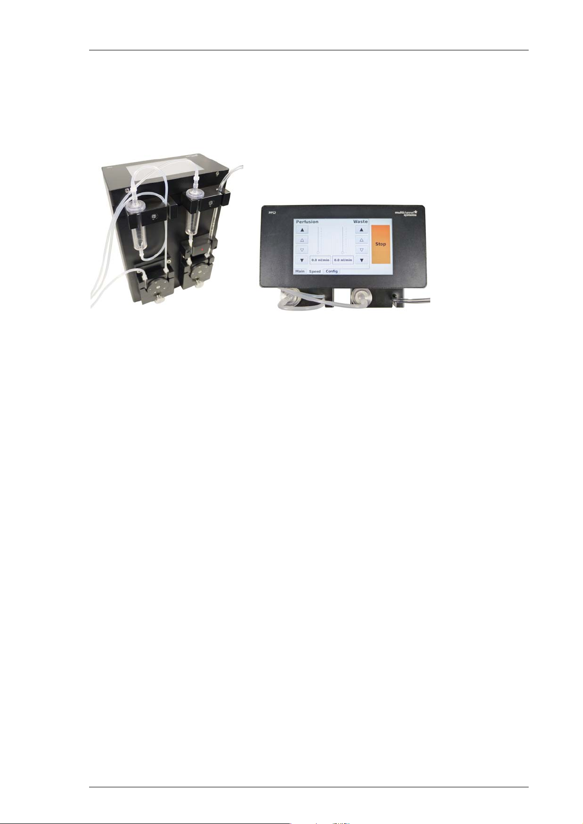
2.1 Welcome to the PPS2 Peristaltic Perfusion System
The peristaltic pump PPS2 with software control is developed for the perfusion of
biological samples. The pumps are driven by stepper motors providing a very long lifetime
without maintenance. The durable brushless motors are extremely reliable, show very
constant rotation speed, are vibration free and have low electromagnetic emission. These
characteristics make the PPS2-System an ideal choice for electrophysiological experiments.
The device consists of two independent peristaltic pumps, one perfusion (inlet) pump
for delivering perfusion solution to the sample, and one waste (outlet) pump to remove
dispensable solution. The droplet isolator chambers avoid pulsation artifacts and allow
optical fluid control.
If you need more than two channels you can connect several PPS2-Systems in serial.
Each pump can still be controlled separately.
The flow rate of the pumps vary between 0 to 30 ml/minute. Other flow rates are available
on demand, please contact MCS.
The PPS2 is a highly flexible system which can be controlled in different ways:
The pump velocity and the flow rate can be controlled from a connected computer
via USB connection and the included software PPS2.
In future versions it will be possible to control the PPS2 with the LTP-Director software
from Multi Channel Systems MCS GmbH. Please see chapter “Software Control”.
Additional analog and digital inputs allow to operate the PPS2 pump via external
inputs, for example from a stimulus generator STG.
It is also possible to operate the pump without software control, via touch screen
on top of the device.
4
Page 7
2.2 Setting Up and Connecting the PPS2 Pump
Warning: Do not start the perfusion until you have double-checked that the perfusion lines
are set up properly and that the inflow and outflow rate are matching. Spilled liquid may
irreversibly damage electronic instruments.
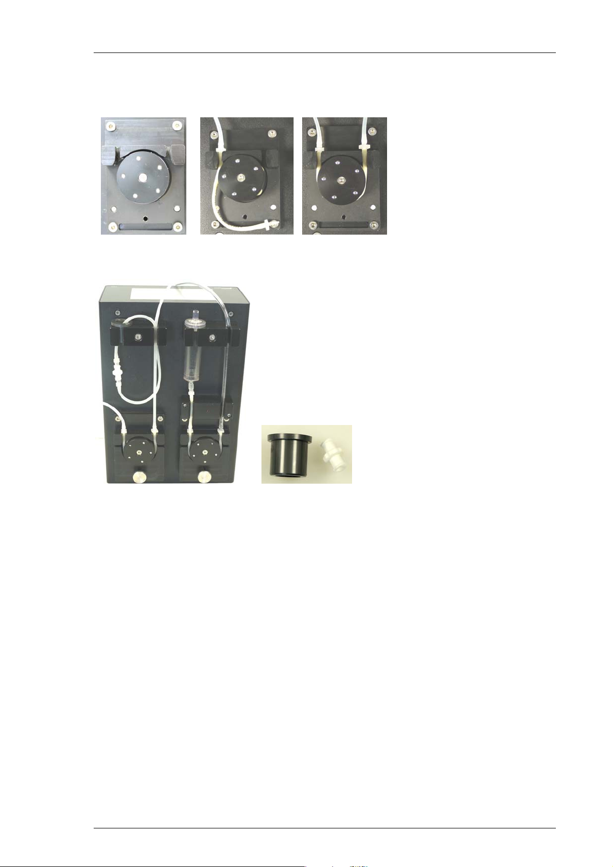
The PPS2 consists of two independent peristaltic pumps, which both are rotating
counterclockwise. The left one is intended for perfusion inlet, the right one for perfusion
outlet. It is of course also possible to use both pumps as independent perfusion inlet pumps,
and to use for example a vacuum pump for suction. This manual will focus on the intended
function as inlet and outlet pumps. Each pump cycle contains a droplet isolator. The outlet
pump is additionally equipped with a bubble detector.
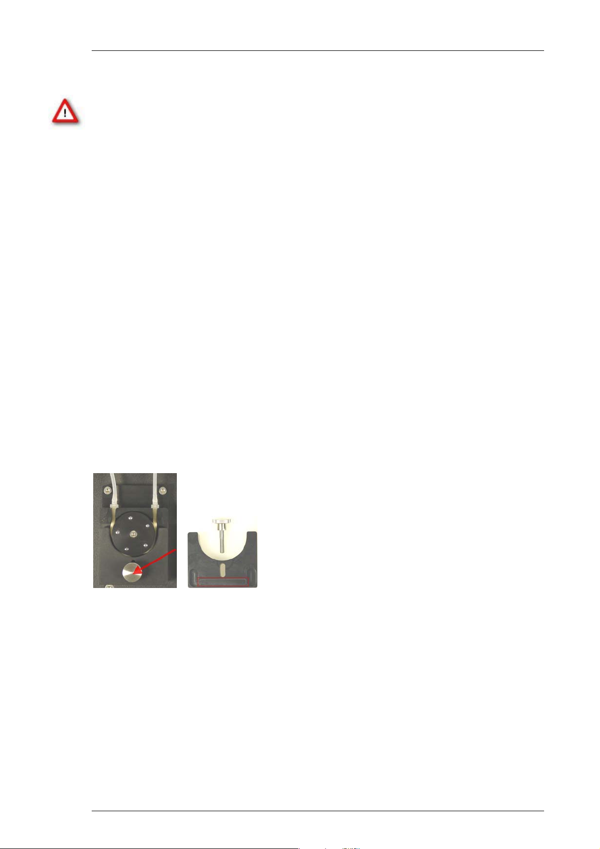
Connecting the Tube Set
The following tubes are used:
Identical Pharmed ® BPT (Saint–Gobain) tubes with an inner diameter of 1.65 mm
and an outer diameter of 3.35 mm around the pump revolver and for the connection
between outlet droplet isolator chamber and outlet pump, where the sensor of the
bubble detector is located.
PPS2 Manual
A PVC tube with larger inner diameter is used for the tube to the waste bottle.
Silicon tubing is used for all other connections.
The specified tubing must be used for the pump revolvers to ensure that the volumes set
in the software are correct. Other tubing can be used for all other connections as well.
Sets of ten tubes for replacement are available from Multi Channel Systems (For example:
PPRT1.65-10 tubes: Pharmed ® BPT, ID: 1.65 mm, OD: 3.35 mm). Additionally you can order
a replacement set for all fluidic components PPS2-Set-F. Please see section “Ordering
Information” in the Appendix.
5
Page 8
Peristaltic Pump Manual
For connecting or changing the tubes, please open the screw and remove the bracket of the
pump revolver. Insert the provided tube and fix it with the luer tube connectors in the denoted
way. To remount the bracket, take care to insert the bar of the bracket into the corresponding
socket on the pump housing. Fix the screw firmly.
If you do not need the droplet isolator, please use the circlet and connect the heads
of the tube with a luer adapter.
2.2.1 Use of Droplet Isolators
The droplet isolators can be used to disrupt the direct liquid column from the pump to the
sample. This can help to remove low frequency noise originating from the pulsation of the
pump head. On the other hand, the droplet isolators make the flow speed inaccurate, and
cause a continued flow even after the pump is stopped. If the flow rate is high (approximate
> 6 – 8 ml/min) the droplet isolators will fill up over time and might even overflow.
The suggested procedure is to start working without the droplet isolators, and use them only
in case unacceptable fluctuations caused by the pump occur in the recordings which can not
be removed otherwise, for example by using a 10 Hz high pass filter.
6
Page 9

PPS2 Manual
Complete Setup
The left pump of the PPS2 is intended for perfusion inlet, the right one for perfusion outlet.
Please connect all tubing and droplet isolators as indicated on the following image. Take
care to use the short Pharmed ® BPT tube between outlet pump and droplet isolator.
Warning: The droplet isolators remove pulsation artifacts, but also cause a continuing
flow even some time after the pumps are stopped. To avoid flooding, please use hose
clamps to stop the flow. Do not forget to open the clamps when you restart the pump.
7
Page 10

Peristaltic Pump Manual
Bubble Detector
The bubble detector connected to the outlet detects the amount of bubbles in the outlet tube.
A low number of bubbles can indicate that the perfusion outlet cycle is not working properly,
so the bubble detector can be used as an alarm system to prevent flooding of the recording
equipment.
The sensor of the bubble detector is on the left side of the LED, the short Pharmed ® BPT tube
has to be guided through the bubble detector as shown on the picture. The LED indicates the
fluid flow: The LED is constantly on without tube, when the fluid flow is not correct it flashes
fast, with correct flow the LED flashes slow. Please pay attention to the LED. See also chapter
“Software”.
Rear Panel
1. Connect the PPS2 pump with the provided power supply cable to the power supply.
2. Connect the PPS2 pump with an USB cable (type A – B) to an USB 2.0 port.
3. If necessary, connect the ground connector to the ground of your recording system.
4. Use the “I/O” switch to switch the PPS2 on and off.
As additional means to control the PPS2, inputs for analog or digital (TTL) signals are provided.
These inputs can be used to start / stop the pump and control the pump speed by external
signals.
It is possible to connect several PPS2 devices via USB hub to one computer to be controlled
by the same software. In future versions the MCS Bus interface can be used to connect several
PPS2 devices in series, also controlled by the same software application.
8
Page 11

2.3 Control Options
The PPS2 perfusion system can be controlled via USB connection by the provided software
PPS2. In future versions it will be possible to control the PPS2 also with the LTP-Director
software from Multi Channel Systems MCS GmbH. The device can also be controlled
independently from a computer connection via touch screen.
2.3.1 Operation of the Perfusion Peristaltic Pump with PPS2 Software
PPS2 Manual
PPS2 software is running on Microsoft Windows ® systems Windows XP or higher.
About
Click the “About” button to see the software version. Free software updates will be available
on the MCS web site. Please check http://www.multichannelsystems.com/downloads/software.
9
Page 12

Peristaltic Pump Manual
Main Window of PPS2 Software
Manual Control Mode
When using more than one PPS2-System, connected via USB cable, one main window tab
page will be available for each PPS2 connected. The tab slider will show the serial number
of the deices. The pumps can be operated independently from each other. Only the “Stop”
button will affect all connected pumps, all other control functions are independent.
The intended use for the PPS2-System is the perfusion of a biological sample on a MEA and
the aspiration of the waste solution. To avoid flooding of the amplifier, the flow rate of the
outlet must always be higher than the flow rate of the inlet. Select the check box “Fixed
Speed Ratio Waste to Perfusion” in %. Via slider or up-down box you can choose the
relation between the velocity of the waste and the perfusion pump. If the “Fixed Speed Ratio”
function is active, both pump speeds will remain at the same relative relation, and only the
control slider for the perfusion pump is active.
The green color of the buttons above the “On” and “Off” buttons indicate that the respective
pump is running. Additionally the speed symbol is rotating.
10
Page 13

PPS2 Manual
Click the button “More” to display further information. At the moment, the default
“Analog Range” of the analog input and the internal “Supply Voltage” is noted.
For using both pumps independently, deactivate the check box “Fixed Speed Ratio”.
With the two sliders, the speed of the left Perfusion (inlet tube) pump, and the right
Waste (outlet tube) pump can be controlled. The unit is milliliter per minute, the maximum
is 30 ml/min for the inlet and 30 ml/min for the drain, if no relation between both parameters
is selected. Alternatively, type the desired value into the text box below the slider or click
the up-down box. The resolution is 100 μl/min. Click the button “On” to start the pump of
your choice and the button above will turn to green. Click “Off” to stop the pump and the
button above turns to grey. It is possible to change the velocity via slider or by writing into
the window while the pump is running. Clicking the button “Fast” sets the pump speed to
maximum as long as the button is pressed. The yellow color indicates the “Fast” mode.
This feature can be used for rinsing the tubes, for example.
The Peristaltic Perfusion PPS2-System has three different operation modes via software and
the additional possibility to control the device without computer connection via touch screen.
Please see chapter “Operation of the Perfusion Peristaltic Pump via PPS2 Touch Screen”.
11
Page 14

Peristaltic Pump Manual
Stop
The “On” and “Off” buttons will affect one pump of the PPS2. The “Stop” button will always
stop both pumps. If several pumps are connected with a serial cable, all connected pumps will
be stopped.
Bubble Detector
The bubble detector can be used as an alarm system to prevent flooding of the recording
equipment. A light barrier detects the changes of fluid to air in the outlet tube and measures
whether this event takes place at least once every ten seconds or not. More than one bubble
per 10 seconds is considered okay, less is considered as an indicator that the fluid flow in the
outlet is too low. The LED is constantly on without tube, when the fluid flow is not correct it
flashes fast, with correct flow the LED flashes slowly.
Select the check box “Use Bubble Detector” to use the function of the bubble detector.
The detector is only active while the pump is running and the “Bubbles” button turns to
green “Startup”.
When fluid flow in the outlet tube is too low or too high, the bubble detector stops the
inlet perfusion pump automatically. The waste pump runs continuously to prevent overflow.
The button turns to red “No”.
External Control: Digital (TTL) and Analog Mode
External control via analog input or digital TTL input allows the same functions as the manual
mode or the controlling via touch screen without software. You can use different modes for
each pump.
The pump speed is still selected in PPS2 software, and the pump status has to be “On”,
as the state of the external input and the pump state are in an logical AND relation:
Digital Mode: The digital input must be “high” AND the pump must be “On” to start
the pump.
Analog Mode: The analog input must be > 0.0 V AND the pump must be “On” to start
the pump.
12
Page 15
PPS2 Manual
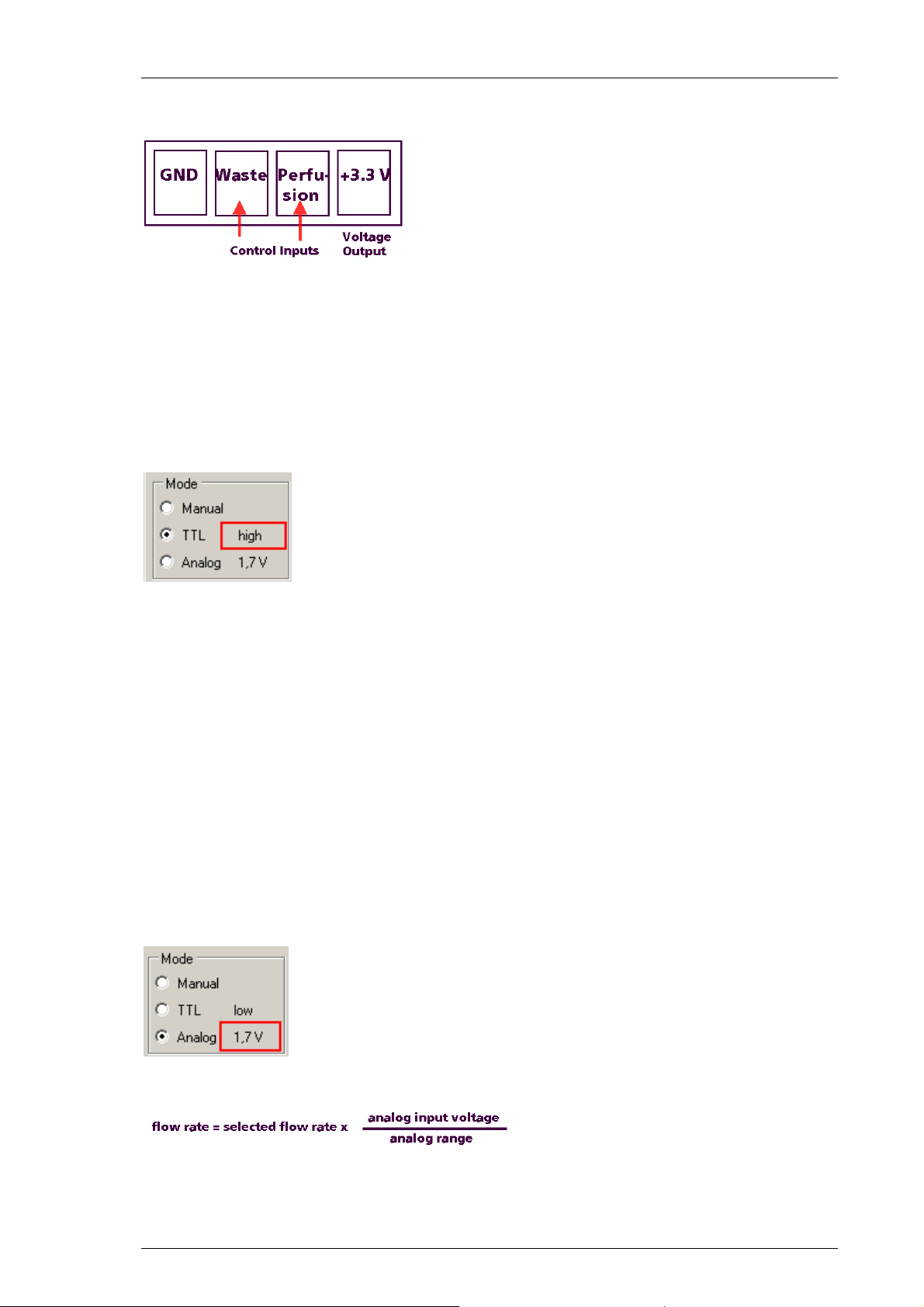
When looking directly to the rear panel of the PPS2 the pin layout of the digital and analog
inputs are as shown on the picture.
Connect either a TTL or an analog output device to the respective inputs and select the
desired control mode in the PPS2 software. In sum (digital and analog input), the maximum
load current for the voltage output (+3.3 V) is 100 mA.
Digital Control
Connect, for example a stimulation generator STG4000, to the “Ground” and “Control
Input(s)” of the digital input on the rear panel. The “Voltage Output” is not needed.
The status of the TTL inputs are displayed in the “Mode” window. If nothing is connected
to the TTL inputs the status is low.
TTL input low ( +0.4 V) pump off.
TTL input high ( +1.5 V ) pump on.
As long as the status of the TTL input is high, the respective pump will run at the speed
selected in PPS2 software. The maximum voltage for the TTL input is +5.5 V.
Analog Control
With the analog control, it is possible not only to start and stop the pump by an external
device, but also the pump speed. Connect an adjustable voltage source, for example a
potentiometer to the “Ground” and “Control Input(s)” of the analog input on the rear panel.
The pin layout of the analog input is the same as for the digital input when looking directly
to the rear panel of the PPS2. If nothing is connected to the analog inputs the status is 0.0 V.
The maximum voltage for the analog input is +10.3 V.
The current voltage level on the analog inputs is displayed in the “Mode” window. The analog
range is by default +5.0 V, as stated in the dialog “More”.
The resulting fluid flow of the pumps can be calculated by the following equation:
Example:
Selected flow rate 5ml/min x (analog input voltage 10 V / analog range 5 V)=10 ml/min.
13
Page 16

Peristaltic Pump Manual
2.3.2 Operation of the Perfusion Peristaltic Pump via PPS2 Touch Screen
Alternatively it is possible to operate the peristaltic pump without software control, via touch
screen on top of the device. The touch screen provides the same control functions of the PPS2
which are available via software. The pumps can be operated independently from each other
or in a fixed ratio. The “Stop” button will always affect both pumps. The touch screen has
three windows, Configuration, Main and Speed.
Configuration Window of PPS2 Touch Screen
Please open the “Configuration” window first because settings done here influence
the settings in the “Main Window” and the “Speed Window”.
Select the check box “Fixed Speed Ratio”. Via up and down arrows you can choose the
relation between the velocity of the waste and the perfusion pump. If the “Fixed Speed
Ratio” function is active, both pump speeds will remain at the same relative relation.
For example 150 % to make sure that the waste pump runs faster than the perfusion pump.
Define a ratio below 100 % and the perfusion pump will run faster than the waste pump.
Note: If the waste perfusion pump is used for the suction of “waste” do not use a ratio below
100 %, this will result in flooding of the connected device!
Bubble Detector
The bubble detector connected to the waste pump tube detects insufficient flow in the waste
tube. This can be an indicator for a problem with the perfusion. A light barrier detects the
changes of fluid to air in the outlet tube and measures whether this event takes place at least
once every ten seconds or not. More than one bubble per 10 seconds is considered okay, less
is considered as an indicator that the fluid flow in the outlet is too low. The LED is constantly
on without tube, when the fluid flow is not correct it flashes fast, with correct flow the LED
flashes slowly. When the bubble detector detects too low fluid flow in the outlet tube, the
inlet perfusion pumps will be stopped automatically. The waste pump runs continuously to
prevent overflow.
Select “Use Bubble Detector” to switch the bubble detector on. This option influences the
“Main Window”. The indicator “Bubbles” is only visible in the main window when the check
box is selected here.
Main Window of PPS2 Touch Screen
In the “Main Window” you can start and stop the pumps separately. The “Fast” mode is,
for example for rinsing the tubes, the pump runs fast as long as the “Fast” button is pressed.
The color of the button above indicates whether a pump is running or not.
14
Page 17

PPS2 Manual
The pictures shows the “Main Window” of the touch screen. The “On” and “Off” buttons
are connected for the operation of both pumps. The grey color of the upper buttons indicate
that no pump is running at the moment, the green color indicates running pumps.
Select the check box “Use Bubble Detector” in “Configuration” to switch the bubble
detector on and the “Bubbles” indicator will be visible in the “Main window”.
In the left picture of the “Main Window” no tube is connected to the bubble detector.
In the right picture no pump is running and therefore no bubbles are detected by the
bubble detector.
“Main Window” when both pumps are running and the bubble detector detects bubbles.
Speed Window of PPS2 Touch Screen
The up down arrows in the “Speed Window” are responsible for controlling the fluid flow.
In the “Speed Window” on the left picture, the speeds of the perfusion and waste peristaltic
pump are independent adjustable with the up down arrows under “Perfusion” and “Waste".
When both pumps are coupled because a “Fixed Speed Ratio” is selected, you control the
speeds of both pumps together via up down arrows under “Perfusion” as shown on the right
picture.
15
Page 18

Peristaltic Pump Manual
2.4 Cleaning and Maintenance
To clean the peristaltic pump system after use, flush all tubes with distilled water for a few
minutes and then quickly with 70 % Ethanol (EtOH). Suck the tubes dry. Disconnect all tube
connectors and unscrew the caps of the compound or waste bottle. Empty the bottles and
wash them out. Take care not to mistake the tubing when reconnecting.
Warning: Make sure no liquid is sucked into the pump revolvers! This can lead to irreversible
damage. Empty the bottle after each experiment. Avoid remaining liquid in the bottle and
tubing, this can result in contamination.
16
Page 19

PPS2 Manual
3 Application Example: MEA2100-System
The peristaltic perfusion PPS2-System consists of two peristaltic pumps. In this application
example, one is connected to a reservoir for ringer solution and pumps solution through
a perfusion heating PH01 to a MEA recording chamber inside a MEA2100 headstage.
The PH01 is connected to a temperature controller TC01/02 and heats the solution to a set
value. A cannula is connected to the second pump, which removes the ringer from the MEA
chamber and pumps it into a waste bottle. PH01 and cannula are positioned by magnetic
perfusion holders MPH. The MPHs connect both perfusion in- and outlet to the ground
of the recording system, via the metal plate in the front of the MEA2100 recording system.
3.1 Setup
1. Provide a power supply in the immediate vicinity of the installation site.
2. Place all devices on a stable and dry surface, where the air can circulate freely and the devices
are not exposed to direct sunlight. Take care not to position the PPS2 and fluid reservoirs
directly above the recording system, to prevent damage by accidentally spilled liquid.
3. Set up the computer with installed PPS2 program and connect the PPS2 with an USB cable.
4. Set up the MEA2100 system as described in the respective manual.
5. Connect the PH01 via tube to the inlet (left) peristaltic pump of the PPS2 and the bottle
with ringer solution.
6. Connect the outlet tube to the outlet (right) peristaltic pump and the waste bottle.
7. Add a hose clamp to the inlet and the outlet tube each.
8. Connect the ground of the PPS2 to the ground on the interface board of the MEA2100,
if necessary.
17
Page 20

Peristaltic Pump Manual
3.2 Perfusion and Noise
Low frequency fluctuations in electrophysiological measurements can be caused by the
perfusion. Shortly switch off the pump to see whether the fluctuations disappear if the pump
is off. 50 Hz noise can also be caused by the perfusion, but is independent of the pump running
or not. Perfusion in and out should contain a piece of metal that can be connected to the
amplifiers ground to remove 50 Hz noise. The easiest way is to use a bend cannula for suction.
In the setup described above, both perfusion in- and outlet are already grounded via the MPHs.
The opening of the cannula should be positioned in a way that it always sucks air and liquid at
the same time, possibly resulting in a constant slurping noise. This prevents the fluid level from
going up and down, which also causes noise. See a suggested perfusion setup below.
Warning: The droplet isolators remove pulsation artifacts, but also cause a continuing flow
even some time after the pumps are stopped. To avoid flooding, please use hose clamps to
stop the flow. Do not forget to open the clamps when you restart the pump.
If you experience low frequency noise from the perfusion, try to optimize the suction as
described above. Additionally, the droplet isolator chambers of the PPS2 interrupt the fluid
flow between pump and recording chamber, and thereby minimize the influence of the pump
head movement on the recordings.
50 Hz noise can be caused by the perfusion of by external noise sources. Remove perfusion in
and out from the bath. If the noise persists, check for external noise sources, like microscope
lamp, power supplies close by and so on. If the noise is caused by the perfusion, check the
grounding of the perfusion in and out. If the magnetic perfusion holders (MPH) from MCS
are used, make sure that there is an electrical contact between PH01, suction cannula, and
the metal plate in front of the MEA2100.
Perfusion Cannula PH01 with Magnetic Perfusion Holder MPH
All MEA amplifiers can be equipped with a magnetic stainless steel plate on top to enable
the use of magnets as perfusion holders. The magnetic perfusion holders MPH also connect
any attached metal cannula directly to the ground of the MEA recording system. The metal
ball holding the cannula allows an accurate positioning of the perfusion tips and a quick and
easy detachment of the perfusion by removing the ball from the magnetic base, if necessary.
The perfusion cannula PH01 with heating element and sensor and a temperature controller
TC01 or TC02 is able to heat the perfusion solution with an accuracy of 0.1 °C to any
temperature from room temperature up to a maximum of 50 °C.
18
Page 21

4 Appendix
4.1 Technical Specifications
PPS2 Manual
General Information
Operating temperature 10 °C to 40 °C
Storage temperature 10 °C to 50 °C
Dimensions (H x W x D) 235 x 160 x 110 mm
Weight 3.6 kg
Number of perfusion pump inlets 1
Number of perfusion pump outlets 1
Maximum perfusion rate inlet 30 ml per minute
Maximum perfusion rate outlet 30 ml per minute
Bubble detector optical fluid flow control
Analog and Digital Input
Maximal voltage of the digital input + 5.5 V
Maximal voltage of the analog input + 10.3 V
Maximal load current ( +3.3 V output) 100 mA
Power Supply
Type SPU63-108
Voltage range @ frequency 100 to 240 VAC @ 47 to 63 Hz
Power consumption 10 W
Software Control
Connection to the computer USB 2.0 High Speed (cable type A – B)
Operating system Microsoft Windows ® 7, Vista or XP with NTFS,
English and German version
19
Page 22

Peristaltic Pump Manual
4.2 Ordering Information
4.2.1 Scope of Delivery
1 PPS2 main device
1 PPS2 CD (Software and Manual)
1 PPS2 power supply (SPU63-108)
1 power cord, country-specific
1 USB 2.0 cable (A – B)
1 PPRT1.65-10
Fluidic: 3 hose clamps, 2 luer adaptors, 2 circlets
Electrical accessories: 1 grounding cable, 1 alligator clip, 2 A/D input connectors
Fluidic devices: 2 PPS2-Set-F
Optionally
1 MCS Bus cable
4.2.2 Replacement
Peristaltic Pump PPS2 Replacement Tube Set
PPRT1.65-10: Unit of 10 peristaltic pump tubes: Pharmed ® BPT (Saint–Gobain),
(ID = 1.65 mm, OD = 3.35 mm, L = 90 mm)
Peristaltic Pump PPS2 Replacement Complete Fluidic
PPS2-Set-F: Set of complete fluidic device components for the PPS2
1 supply tube (Silicon L =1000 mm)
1 interconnection tube (Silicon L = 210 mm)
1 detector tube (Pharmed ® BPT L = 45 mm)
1 waste tube (PVC L = 1000 mm)
2 sample tube (Silicon L = 1000 mm)
2 drip chamber bodies with cover
20
Page 23

Peristaltic Pump PPS2 Replacement Fluidic Accessories
PPS2-Set-FA: Fluidic accessories
3 hose clamps
2 luer adapter
2 circlets
Peristaltic Pump PPS2 Replacement Electrical Accessories
PPS2-Set-EA: Electrical accessories
1 alligator clip
1 grounding cable
2 D / A input connectors
4.2.3 Data Sheet
PPS2 Manual
21
Page 24

Page 25

Page 26

Peristaltic Pump Manual
4.3 Contact Information
Local retailer
Please see the list of official MCS distributors on the MCS web site.
User forum
The Multi Channel Systems MCS GmbH User Forum provides the opportunity
for you to exchange your experience or thoughts with other users worldwide.
Mailing list
If you have subscribed to the Mailing List, you will be automatically informed about
new software releases, upcoming events, and other news on the product line.
You can subscribe to the list on the contact form of the MCS web site.
www.multichannelsystems.com
22
 Loading...