

Page 1

32-Channel Miniature Preamplifier
Manual
Page 2

Page 3

Information in this document is subject to change without notice.
No part of this document may be reproduced or transmitted without the express written
permission of Multi Channel Systems MCS GmbH.
While every precaution has been taken in the preparation of this document, the publisher
and the author assume no responsibility for errors or omissions, or for damages resulting
from the use of information contained in this document or from the use of programs and
source code that may accompany it. In no event shall the publisher and the author be liable
for any loss of profit or any other commercial damage caused or alleged to have been caused
directly or indirectly by this document.
© 2014 Multi Channel Systems MCS GmbH. All rights reserved.
Printed: 11. 02. 2014
Multi Channel Systems
MCS GmbH
Aspenhaustraße 21
72770 Reutlingen
Germany
Fon +49-71 21-90 92 5 - 0
Fax +49-71 21-90 92 5 -11
info@multichannelsystems.com
www.multichannelsystems.com
Microsoft and Windows are registered trademarks of Microsoft Corporation. Products that
are referred to in this document may be either trademarks and/or registered trademarks
of their respective holders and should be noted as such. The publisher and the author
make no claim to these trademark.
Page 4

Page 5

Table of Contents
1 Important Information and Instruction 1
1.1 Operator's Obligations 1
1.2 Guarantee and Liability 1
1.3 Important Safety Advice 2
2 Welcome to the MPA32I 3
3 Setting Up and Connecting the MPA 4
3.1 General Setup Recommendations 4
3.2 Testing the Noise Level of the Setup 5
4 Setting up MC_Rack 6
5 Connecting FlexMEAs 8
5.1 EcoFlexMEAs 10
5.1.1 Connecting 32-Channel NeuroNexus Probes 11
5.1.2 Adapter-NN-32 Pin Layout 12
5.2 Connecting 54-Channel NeuroNexus Probes 13
6 Service and Maintenance 15
7 Pin Layout 16
7.1 Power Supply 16
7.2 Test Model Probe 17
8 Contact Information 18
9 Technical Specifications MPA32I 19
10 Datasheet 20
Page 6

Page 7

Important Information and Instruction
1 Important Information and Instruction
1.1 Operator's Obligations
The operator is obliged to allow only persons to work on the device, who
are familiar with the safety at work and accident prevention regulations and have been
instructed how to use the device;
are professionally qualified or have specialist knowledge and training and have received
instruction in the use of the device;
have read and understood the chapter on safety and the warning instructions in this manual
and confirmed this with their signature.
It must be monitored at regular intervals that the operating personnel are working safely.
Personnel still undergoing training may only work on the device under the supervision
of an experienced person.
1.2 Guarantee and Liability
The General conditions of sale and delivery of Multi Channel Systems MCS GmbH always apply.
The operator will receive these no later than on conclusion of the contract.
Multi Channel Systems MCS GmbH makes no Guarantee as to the accuracy of any and all tests
and data generated by the use of the device or the software. It is up to the user to use good
laboratory practice to establish the validity of his findings.
Guarantee and liability claims in the event of injury or material damage are excluded when they
are the result of one of the following.
Improper use of the device.
Improper installation, commissioning, operation or maintenance of the device.
Operating the device when the safety and protective devices are defective and/or inoperable.
Non-observance of the instructions in the manual with regard to transport, storage, installation,
commissioning, operation or maintenance of the device.
Unauthorized structural alterations to the device.
Unauthorized modifications to the system settings.
Inadequate monitoring of device components subject to wear.
Improperly executed and unauthorized repairs.
Unauthorized opening of the device or its components.
Catastrophic events due to the effect of foreign bodies or acts of God.
1
Page 8

32-Channel Miniature Preamplifier Manual
1.3 Important Safety Advice
Warning: Make sure to read the following advices prior to install or to use the device and the
software. If you do not fulfill all requirements stated below, this may lead to malfunctions or
breakage of connected hardware, or even fatal injuries.
Warning: Obey always the rules of local regulations and laws. Only qualified personnel should
be allowed to perform laboratory work. Work according to good laboratory practice to obtain
best results and to minimize risks.
The product has been built to the state of the art and in accordance with recognized safety
engineering rules. The device may only
be used for its intended purpose;
be used when in a perfect condition.
Improper use could lead to serious, even fatal injuries to the user or third parties and damage
to the device itself or other material damage.
Warning: The device and the software are not intended for medical uses and must not be used
on humans.
Malfunctions which could impair safety should be rectified immediately.
Any physical damage of the cable, such as a broken cable, causes a physical damage of the
miniature preamplifier that cannot be repaired.
Protect the device from heat. Do not autoclave!
You can clean the connectors with distilled water in an ultra sonic bath, but keep the cable away
from the fluid. Dry the device with compressed air.
Use and keep the device always in a dry environment. Do not expose it to fluids or vapor for
a longer period of time.
2
Page 9
2 Welcome to the MPA32I
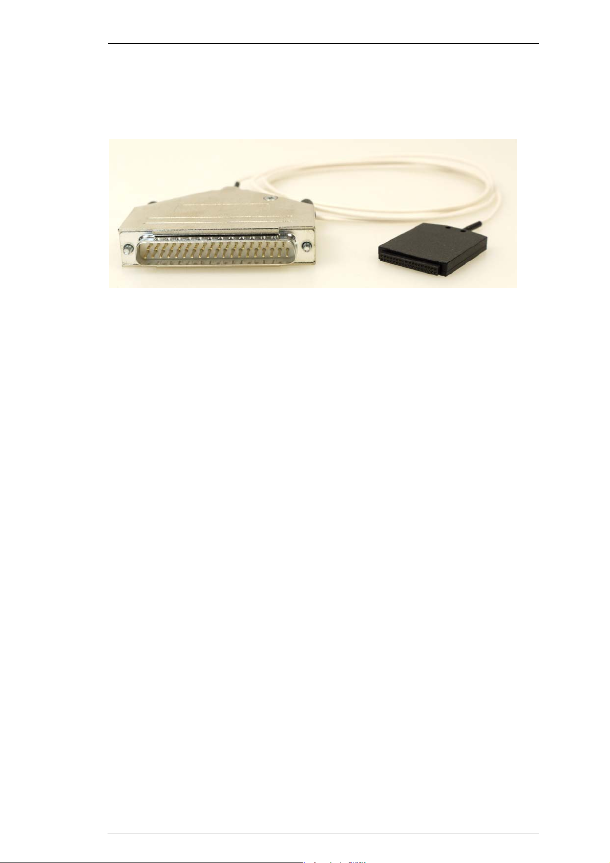
The 32-Channel Miniature Preamplifier MPA32I is connected to the microelectrodes for providing
the initial tenfold amplification stage.
FlexMEAs
It has additional common ground and reference electrode inputs. The reference electrode
is ideally identical to the recording electrodes and placed into a comparable but inactive area or
tissue. Background or noise signals that are picked up by both the reference electrode and the
recording electrodes are removed.
The metal case provides electrical shielding. Electrode damage is prevented by the very
low bias current. The high input impedance ensures stable long-term recordings:
Ideally, the input impedance would be infinite. As low voltages are generally recorded, a high
current would flow if the input impedance were low. As a result, the amplifier would not be able
to deliver the current, and the voltage would break down. The miniature preamplifier has a high
input impedance to avoid this problem.
Adapters for all standard microelectrodes such as NeuroNexus probes (from
www.neuronexustech.com) for acute and chronic implantations ensure a close proximity to the
probe to minimize signal loss and cross talk. Adapters are not included in the standard scope of
delivery and have to be ordered separately. For custom adapters, please ask your local retailer or
contact Multi Channel Systems.
3
Page 10
32-Channel Miniature Preamplifier Manual
3 Setting Up and Connecting the MPA
3.1 General Setup Recommendations
In the following, you find general recommendations for the installation.
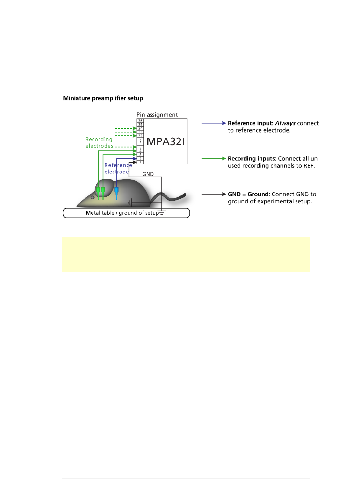
Important: It is important that the complete setup refers to a single common ground. The
reference input has always to be connected. It is recommended to use a reference electrode.
However, if you are not using a reference electrode, connect the reference input to ground
(GND). Otherwise, noise picked up by the reference input will be subtracted from the recording
signals. This will either lead to signal loss or to a very high noise level.
1. Ground the animal with a ground electrode of large surface area, for example, a liquid gel
adhesive electrode, that is connected to the ground of the setup, for example, a large metal
table or a Faraday cage, to avoid pickup of noise from the environment. The ground electrode
is best positioned in an electrically inactive region (not near muscle, nor heart), for example, at
the belly.
2. Connect the GND input or the metal case of the miniature preamplifier to the common
ground of the setup. (The GND input is internally connected to the metal case.)
3. Connect the reference electrode to the reference input of the miniature preamplifier.
Generally, a reference electrode is inserted into non-active tissue of the experimental model.
The reference electrode should be identical to the recording electrode so that both electrodes
see the same background noise. This is necessary because despite the grounding, the animal’s
body often has not exactly a potential of zero, due to the electrode impedance, for example.
The background noise is then subtracted from the recording signal, increasing the signal to
noise ratio. Please note that this may not work if the complete setup is not properly grounded.
4. (Optional) If two reference electrodes are used, connect the second electrode to the free
reference input. Otherwise, leave it free. It is generally not necessary to use a second reference
electrode. It can be used to enlarge the surface area of the reference, though.
5. Connect the recording electrodes to the recording channels of the miniature preamplifier.
You can either use single electrodes or multitrodes with the miniature preamplifier. MCS provides
adapters for standard probes.
4
Page 11
6. Connect all unused recording channels to the GND input or to the reference electrode if the
reference and ground electrode of the amplifier are short circuited, to avoid noise pickup. As the
total amplifier gain generally lies in the range of 1000, even very small noise signals may generate
high noise signals.
7. If you are not using a Faraday cage, it might be necessary to shield the complete setup with
aluminum foil or similar to prevent electrical interference from the outside. Connect the
aluminum foil to the ground of the setup (for example, the metal table).
Troubleshooting: If you observe problems with noise, check that the ground of the setup
is connected to exactly the same ground as the data acquisition computer. For example,
connect the metal table to the ground / earth wire of a free power outlet (of the same electrical
system), as the computer is generally connected to ground/earth via the power plug, too.
Also, connect the data acquisition computer’s metal case with a thick ground wire
to the ground of the setup (for example, the metal table), preferably with a 4 mm plug.
3.2 Testing the Noise Level of the Setup
FlexMEAs
A terminal plug that connects all inputs to ground, and a test model probe that mimics the
electrode impedance are provided for testing the noise level of the setup. Please note that all
instruments were thoroughly tested at the factory site before delivery. The suggested tests are
mainly intended for optimizing and troubleshooting your setup, to exclude any damage that
might have occurred during transportation, or to fulfill your own guidelines, for instance. It will
take only a few minutes time and can save time and trouble in the long run. Multi Channel
Systems recommends running these tests before you start your real experiments.
1. Connect the terminal plug to one miniature preamplifier and the test model probe to the other
as shown in the picture (do not mismatch the polarity). If you have only one MPA32I, you can
perform the two tests consecutively.
2. Connect the MPA32I with the test model probe to channels 1 to 32 of the signal collector.
3. Connect the MPA32I with terminal plug to channels 33 to 64 of the signal collector.
4. Make sure that all other connections are appropriate, and that your setup has an appropriate
grounding and shielding as recommended in the chapter “General Setup Recommendations”.
5
Page 12

32-Channel Miniature Preamplifier Manual
4 Setting up MC_Rack
Please refer to the MC_Rack Manual for more information.
Start MC_Rack.
Open the file MPA32I_NoiseTest.rck on the installation volume (see folder Tutorial).This rack
contains the virtual MC_Card instrument as data acquisition device with a continuous raw data
display and an Analyzer to measure the peak-to-peak amplitude.
Click Start to start the recording.
— OR — Set up the rack on your own:
Click Data Source Setup on the Edit menu. Select a 1-dimensional layout. Select the number
of electrode channels (at least 32).
Add the data acquisition to your virtual rack.
In the tree view pane of the virtual rack, select the data acquisition, and click the Hardware
tab. Enter the total amplifier gain according to the specifications of the instruments. For example,
for a miniature preamplifier with a gain of 10 and a following filter amplifier with a gain of 100,
the total gain is 1000.
Select an input voltage range of –819.2 to +818,8 mV and a sampling rate of 10000 Hz.
On the Edit menu, click Add Data Display to add a raw data display to your virtual rack.
In the virtual rack tree view pane, select the Display 1 and click the Layout tabbed page.
Set up a channel map with channels 1 to 64.
Adjust the display ranges to 500 ms and +/–50 μV.
On the Edit menu, click
typical channels on the Channels tabbed page. Select the Peak-Peak Amplitude parameter on
the Analyzer tabbed page.
On the Edit menu, click Add Parameter Display to add a Parameter Display to the virtual
rack.
In the virtual rack tree view, select the Display 2 and click the Layout tabbed page. Set up
a channel map with all channels that were assigned to the Analyzer.
Add Analyzer to add an Analyzer to the virtual rack. Select all or two
Click the Ranges tabbed page and enter 0 to 10 s for the x- range and 0 to100 μV for the
y- range.
6
Page 13

FlexMEAs
Typical Results
Typical results of this test are shown in the following screen shot. The filter amplifier used for this
test had a gain of 100 and a bandwidth of 0.5 to 5000 Hz (FA64I-100-0.5-5000). If you use a
filter amplifier with a narrower bandwidth, you can generally expect a slightly lower noise level.
Noise level test with #MPA8I and FA64I-100-0.5-5000 filter amplifier.
The noise level is 60 μV peak to peak with the provided test model probe (channels 1 – 32)
and 20 μV peak to peak with grounded inputs (channels 33 – 64). The top window shows
raw data; the bottom window shows the extracted peak-to-peak amplitudes of channels
1 and 33. (The miniature preamplifier was shielded by a metal case connected to the ground /
earth of the test lab.)
7
Page 14

32-Channel Miniature Preamplifier Manual
5 Connecting FlexMEAs
FlexMEA36, plastic spacer and adapter (ADPT-FM-32) connected to a 32-channel miniature
amplifier MPA32I.
The side with no screws is considered the top side of the MPA32I. If the adapter is oriented
as shown in the figure, the FlexMEA36 is inserted with the contact pads facing downward.
For connecting the FlexMEA72 you need the adapter ADPT-FM-72. Please see the datasheet
FlexMEA72 in the Appendix.
Connecting the FlexMEA36
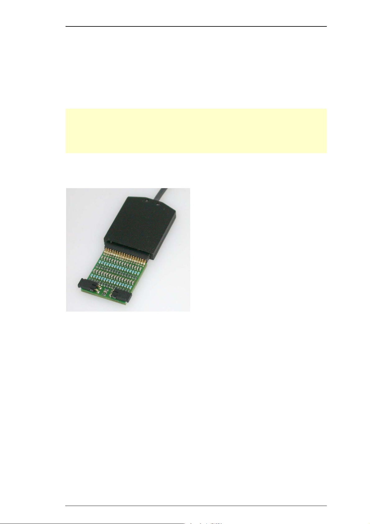
The FlexMEA adapter has a drawer for inserting the FlexMEA36. Open the slot of the white
drawer. Grip the sides of the white slot cover with your fingers and carefully pull open the slot
cover only a little bit (about 1 or 2 mm). Do not demount the cover as the plastic supports might
break easily.
Insert the FlexMEA36 into the slot of the drawer, with the contact pads upside down .Insert the
plastic spacer into the slot of the drawer.
Important: Please use a thin plastic spacer between the FlexMEA36 and the connector so that the
contact pads make a tight contact to the connector pins. Otherwise, the FlexMEA36 will sit too
loose and will have a bad contact resulting in a higher noise level. The spacer should be placed
on the opposite side of the contact pads of the FlexMEA36 in the drawer.
Carefully push back the slot cover of the white drawer until it locks.
8
Page 15

FlexMEAs
FlexMEAs
FlexMEAs are made of flexible polyimide material (Polyimide 2611 foil), perfect for in vivo
and special in vitro applications. Only 12 μm "thick" and weighing less than 1 g, the FlexMEA
biosensor is very thin and lightweight.
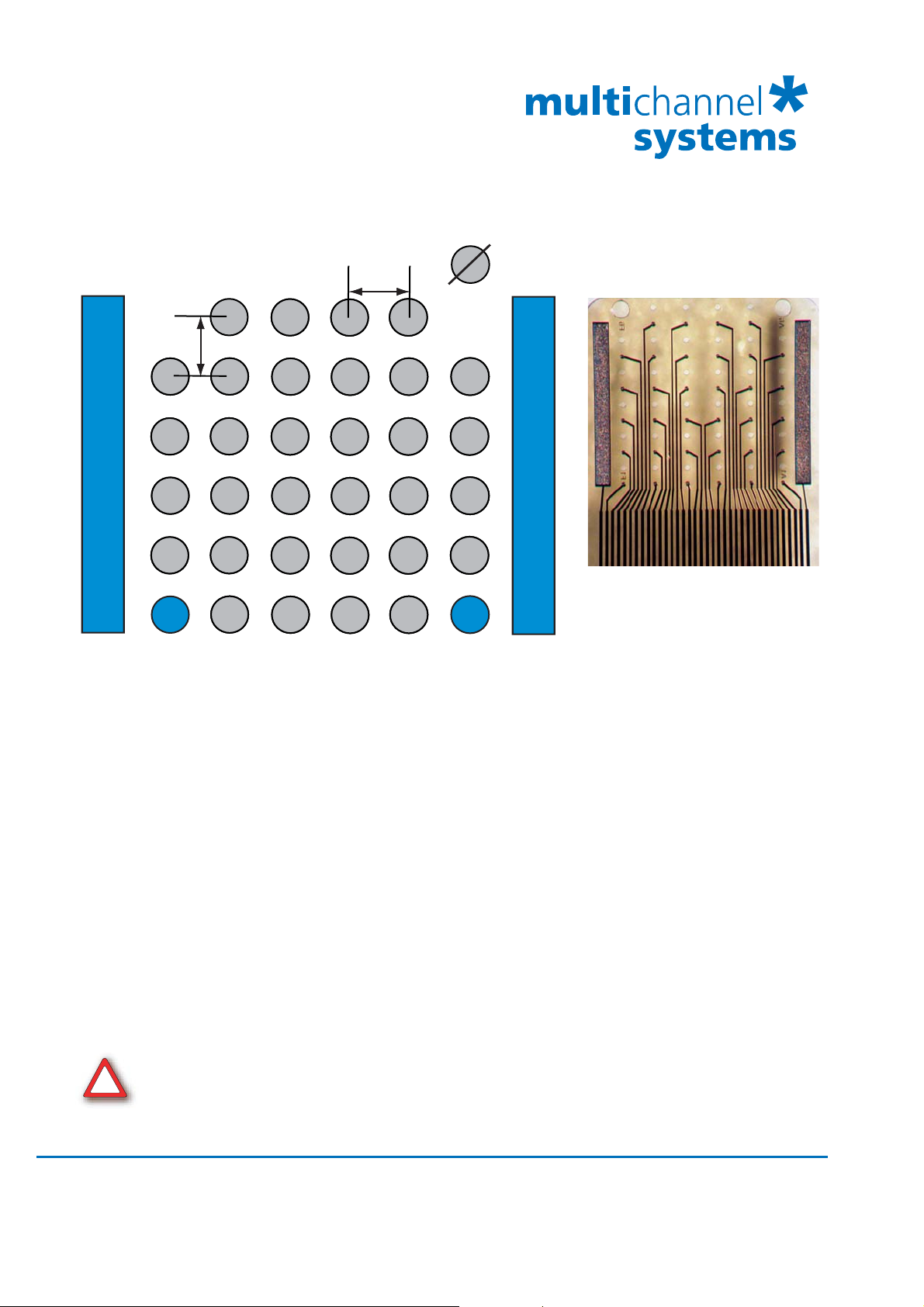
FlexMEA36 has 32 titanium nitride (TiN) electrodes plus two
internal reference electrodes and two ground electrodes.
The flexible base is perforated for a better contact with
the surrounding tissue.
The electrodes have a diameter of about 30 μm with
an interelectrode distance of 300 μm.
Contact pads and conducting material is pure gold.
FlexMEA72 has 72 titanium nitride (TiN) electrodes plus
four internal reference electrodes and four ground
electrodes. The flexible base is perforated for a better
contact with the surrounding tissue.
The electrodes have a diameter of about 100 μm with
an interelectrode distance from 625 to 750 μm.
Contact pads and conducting material is pure gold.
Using FlexMEAs
FlexMEAs are usually connected to a headstage preamplifier that is connected to a filter amplifier
or programmable gain amplifier (see also the ME-System product line of Multi Channel Systems
MCS GmbH). FlexMEAs can be via adapter connected to a 32-channel miniature preamplifier
MPA32I from Multi Channel Systems for in vivo experiments. FlexMEAs are stable at a
temperature range from 10 °C to 40 °C.
Warning: Do not autoclave or sterilize FlexMEAs by heat. These MEA types are not heat stable
and will irreversibly damaged if the temperature is too high.
Do not use ultrasonic bath for cleaning!
9
Page 16

32-Channel Miniature Preamplifier Manual
5.1 EcoFlexMEAs
EcoFlexMEAs are made of flexible polyimide material (Kapton), perfect for in vivo and special in
vitro applications. Only 50 μm "thick" and weighing less than 10 g, the EcoFlexMEA biosensor
is thin and lightweight.
EcoFlexMEA36 has 32 gold electrodes plus two internal reference electrodes and two ground
electrodes. The flexible base is perforated for a better contact with the surrounding tissue. The
gold electrodes have a diameter of about 50 μm with an interelectrode distance of 300 μm and
an impedance of approximately 50 kOhm. Contact pads and conducting material is pure gold.
EcoFlexMEA24 has 24 gold electrodes plus two internal reference electrodes and two ground
electrodes. The flexible base is perforated for a better contact with the surrounding tissue. The
gold electrodes have a diameter of about 80 μm with an interelectrode distance of 300 μm and
an impedance of approximately 50 kOhm. Contact pads and conducting material is pure gold.
EcoFlexMEAs are usually connected to a headstage preamplifier MPA31I that is connected to
a filter amplifier or programmable gain amplifier (see also the ME-System product line of Multi
Channel Systems MCS GmbH). EcoFlexMEAs can be directly connected to a 32-channel miniature
preamplifier from Multi Channel Systems for in vivo experiments. EcoFlexMEAs are stable at a
temperature range from 10 °C to 125 °C and can be autoclaved.
10
Page 17

5.1.1 Connecting 32-Channel NeuroNexus Probes
Important: REF has to be connected for obtaining a proper signal.
Insert the pin array of the NeuroNexus probe into the black connector of the ADPT-NN-32.
FlexMEAs
Connect the MPA32I to the adapter outputs. Make sure that the orientation of the MPA32I
is correct (see illustration).
11
Page 18

32-Channel Miniature Preamplifier Manual
5.1.2 Adapter-NN-32 Pin Layout
The indicated numbers are the ME-System channel numbers that will show up in the MC_Rack
program. GND is the ground, REF is the reference input of the miniature preamplifier.
Channel Assignment NeuroNexus Probe to MPA32I and MC_Rack
The following list shows the assignment to the electrode numbers as given by NeuroNexus
Technologies.
12
Page 19

5.2 Connecting 54-Channel NeuroNexus Probes
Important: REF has to be connected for obtaining a proper signal.
Connect the two MPA32I to the ADPT-NN-54 adapter outputs. Make sure that the orientation
of the amplifiers is correct (see illustration).
FlexMEAs
13
Page 20

32-Channel Miniature Preamplifier Manual
ADPT-NN-54 Pin Layout
Numbers in italics are the MPA32I pin numbers. The electrode numbers are aligned
to the input pins of the MPA32I.
The next figure shows the numbering of the polytrode electrodes.
14
Page 21

6 Service and Maintenance
Cleaning the Connectors
Warning: It is recommended to avoid the use of cleaning solutions to avoid corrosion. If a wet
cleaning is required, use distilled water. Make sure that only the connectors touch the liquid;
do not submerge the miniature preamplifier or the cable. Otherwise, you can fatally damage
the electronics.
Clean the connectors with 70 % alcohol and cotton swabs from time to time.
If this does not provide satisfying results, insert only the connectors into a small beaker with
acetone or alcohol and treat them in an ultrasonic bath for 10 to 20 s. Air-dry the miniature
preamplifier for about 5 min before use.
You can also clean the connectors with distilled water in an ultra sonic bath. Dry the
connectors with compressed air immediately after sonication and let the amplifier air dry for
at least 6 h before use.
Sterilization
Service and Maintenance
Warning: Do not autoclave or sterilize miniature preamplifiers by high heat (above 70 °C) or
vapor. The resin is not heat-stable and may deform under heat. Vapor can lead to a corrosion
of the electronics.
Miniature preamplifiers can be sterilized with standard methods that are not based on high heat
or vapor, for example, with 70 % ethanol, UV-light, or by thermal sterilization in an oven at
56 °C with an incubation time of 8 hours.
15
Page 22

32-Channel Miniature Preamplifier Manual
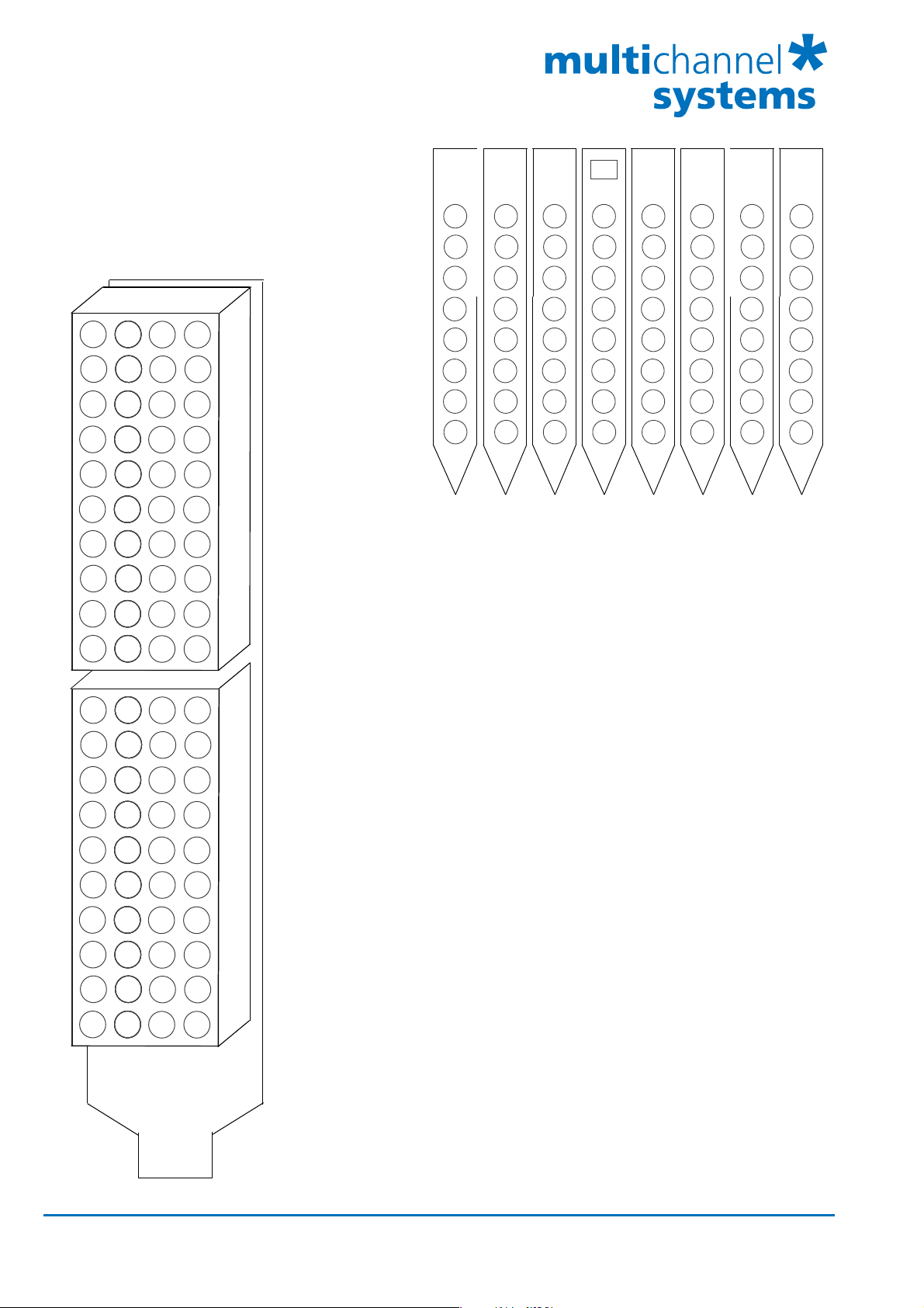
7 Pin Layout
7.1 Power Supply
Supply voltage is applied to the output connector pins 19 and 37. The voltage source should
supply a stable noise-free voltage. Do not exceed the maximum voltage.
Pin 19: –3 V to –8 V
Pin 37: +3 V to +8 V
Warning: Do not mismatch the polarity of the power supply. A false connection may damage
the unit.
Input Connector
This illustration shows the pin layout viewed from the front, with the case screws upside down.
The two reference inputs are used for connecting a reference electrode. Both inputs are equal,
so it does not matter which of the two inputs is used. If both are used, the mean of both
reference signals is used as reference.
Output Connector
The signal ground is connected to the ground of the amplifier. The signal ground is used as
the reference for the following filter amplifier.
16
Page 23

7.2 Test Model Probe
Test signal IN: You can use the jumper to connect the signal input pin (Signal IN) to ground
(standard situation for a noise level test), or you can connect a data source, for example, a sine
wave generator to the input (and the ground of the test signal to the signal ground input) to test
the signal distribution. The input signal is distributed across all recording channels.
Pin Layout
REF I N: The standard situation in an experiment should be that the reference electrode has
properties identical or close to the recording electrodes. You can remove the jumper to connect
the reference output of the test model probe to the same resistors as the recording channels to
mimic the experimental situation, or you can use the jumper to connect the reference output to
ground.
DC
Dynamic
Capacitanc 150 pF
4.7 M
330 k
17
Page 24

32-Channel Miniature Preamplifier Manual
8 Contact Information
Local retailer
Please see the list of official MCS distributors on the MCS web site.
User forum
The Multi Channel Systems User Forum provides an excellent opportunity for you to exchange
your experience or thoughts with other users worldwide.
Mailing list
If you have subscribed to the ME-System mailing list, you will be automatically informed about
new software releases, upcoming events, and other news on the product line. You can subscribe
to the list on the contact form of the MCS web site.
www.multichannelsystems.com
18
Page 25

9 Technical Specifications MPA32I
Operating temperature 0° C to 50° C
Storage temperature 0° C to 50° C
Relative humidity 10 % to 85 % non-condensing
Dimensions (W x D x H) 27 x 36 x 5 mm
Weight 7 g w/o cable and plug, 56 g with cable and plug
Length of the cable 1.5 m
Maximum tensile strength of
20 N
cable
Input connector type Dual-row precision sockets, 50 mil (1.27 mm)
grid pattern, for 0.35 to 0.45 mm round pins
Supply voltage ± 3 V to ± 8 V DC
Supply current < ± 14 mA, typically ± 9 mA
Number of input channels 32
Input voltage ± 500 mV (with respect to a supply voltage of 5 V)
Input impedance
Input noise < 1.5 μV
Noise density
12
parallel to 10 pF
10
(1 Hz to 5 kHz, inputs short-circuited)
RMS
= 15 nV / Hz
e
n
Number of output channels 32
Output voltage = supply voltage
Output current max. = 10 mA
Output impedance
0
Bandwidth DC to 50 kHz
Gain 10
19
Page 26

32-Channel Miniature Preamplifier Manual
10 Datasheet
20
Page 27

FlexMEA36
Flexible Microelectrode Array with 36 electrodes for use with 32-Channel Miniature
Preamplifier MPA32I-Flex or with the ADPT-FM-32 adapter and the standard MPA32I.
2200
Dimensions in m
31000
5000
3000
350
500
Technical Specifications FlexMEA36
Temperature compartibility 10 - 40 °C
Dimension (W x D) 31 mm x 18.5 mm
Thickness of the electrode field 12 m
Weight < 1 g
Base material Polyimide 2611 foil
Contact pads and track material Gold
Electrode diameter 30 m
Interelectrode distance (centre to centre) 300 m
Perforation Diameters of the holes 30 m
Electrode height Planar
Electrode type TiN electrodes (Titanium nitride)
Isolation type Polyimide 2611 foil
Electrode impedance Approximately 50 k
Electrode layout grid 6 x 6
Number of recording electrodes 32
Number of reference electrodes 2 internal reference electrodes
Number of ground electrodes 2
18500
MC_Rack
Source layout in “Data Source Setup” Configuration, 64 channels, Amplifier: FA64I/S or FA32I/S,
MEA: FlexMEA36 (FlexMEA36.cmp).
Channel Map “Default Map” in Layout tab of Data Display.
Cleaning Rinse with distilled water, optional with ethanol 70 %.
Do not autoclave or sterilize FlexMEAs by heat. These MEA types are not heat-stable
and will be irreversibly damaged! Please do not use ultrasonic bath for cleaning.
Multi Channel Systems
MCS GmbH
Aspenhaustrasse 21
72770 Reutlingen
Germany
Fon +49-7121-9 09 25Fax
+49-7121-9 09 25-11
info@multichannelsystems.com
www.multichannelsystems.com
0
© 2014 Multi Channel Systems MCS GmbH
Product information is subject to change
without notice.
Page 28
FlexMEA36
28
22
11
5
29
27
21
12
6
4
30
23
20
13
10
3
31
24
17
16
9
2
32
25
18
15
8
1
26
19
14
7
Electrode Layout
GND
300 m
B1 B2 B3 B4 B5 B6
C1 C2 C3 C4 C5 C6
D1 D2 D3 D4 D5 D6
E1 E2 E3 E4 E5 E6
REF
F2 F3 F4 F5
300 m
A2 A3 A4 A5
10
11
12
13
16
15
14
22
21
20
17
18
19
25
26
28
27
23
24
30 m
29
30
31
32
REF
GND
The numbers in the electrodes are the recording channel numbers that refer to the channel numbers in the
data acquisition program. Please make sure that you have selected “Configuration” in the “Channel Layout”
under “Data Source Setup” with a total number of 64 channels. In “Amplifier”, please choose FA32I/S or
FA64I/S and in “MEA” FlexMEA36. In Layout tab of the display, please click ”Default Map”.
The letter digit code below is the electrode identifier and refers to the position of the electrode in the grid.
Important: The channel map is constructed by looking on the back side of the electrodes, because the FlexMEA
electrodes are placed on the preparation upside down!
If you use more than one MPA32I-Flex and a MEA64-System, the signal collector SC2x32 leads the output
channels of the second amplifier to channel number 33 to 64. Please see datasheet SC2x32 for details.
The side with the writing NMI is the correct side with the contact pads and electrodes. It might be a bit confusing
that the pads look stronger from the wrong side, but if you hold the FlexMEA into the light, you see that the pads
have a 3-dimensional appearance only from the correct side.
Warning: The device may only be used together with the MPA32I (-Flex)
!
from Multi Channel Systems MCS GmbH, and only for the specified purpose.
Damage of the device and even injuries can result from improper use.
Multi Channel Systems
MCS GmbH
Aspenhaustrasse 21
72770 Reutlingen
Germany
Fon +49-7121-9 09 25Fax
+49-7121-9 09 25-11
info@multichannelsystems.com
www.multichannelsystems.com
0
© 2014 Multi Channel Systems MCS GmbH
Product information is subject to change
without notice.
Page 29

ADPT-FM-32
FlexMEA36 Adapter for
32-Channel Miniature Preamplifiers MPA32I
Connecting the FlexMEA36 via Adapter ADPT-FM-32 to the MPA32I.
Plastic
Spacer
FlexMEA36
MPA32I
ADPT-FM-32
MPA32I: The side with no screws is considered the top side of the MPA32I.
ADPT-FM-32: If the adapter ADPT-FM-32 is oriented as shown in the figure, the FlexMEA36
must be inserted with the contact pads facing downward. Open the white drawer of the adapter.
FlexMEA36: Insert the FlexMEA36 carefully into the drawer of the adapter.
Please use the plastic spacer to fix the FlexMEA36 in the drawer of the adapter ADPT-FM-32,
and to ensure the contact.
Plastic Spacer: Insert the plastic spacer carefully into the drawer of the adapter.
The plastic spacer should be placed in the opposite side of the contact pads of the FlexMEA36,
otherwise the connection will be interrupted.
Close the white drawer of the adapter ADPT-FM-32.
If you like to use the FlexMEA36 together with the standard 32-channel miniature preamplifier MPA32I,
you need the ADPT-FM-32 adapter to connect the FlexMEA36 to the standard MPA32I.
There is no need for an adapter if you use the 32-channel miniature preamplifier MPA32I-Flex,
which is specified for FlexMEAs. Please read the MPA32I-Flex manual for more information.
Multi Channel Systems
MCS GmbH
Aspenhaustrasse 21
72770 Reutlingen
Germany
Fon +49-7121-9 09 25Fax
+49-7121-9 09 25-11
info@multichannelsystems.com
www.multichannelsystems.com
0
© 2014 Multi Channel Systems MCS GmbH
Product information is subject to change
without notice.
Page 30

FlexMEA72
Flexible Microelectrode Array with 72 electrodes for use via ADPT-FM-72 adapter with
two 32-Channel Miniature Preamplifier MPA32I for in vivo and in vitro applications.
Technical Specifications FlexMEA72
Temperature compartibility 10 - 40 °C
Dimension (W x D) of the FlexMEA72 42 mm x 12 mm
Thickness of the electrode field 12 m
Weight < 1 g
Base material Polyimide 2611 foil
Contact pads and track material Gold
Electrode diameter 100 m
Interelectrode distance (centre to centre) 625 to 750 m
Perforation Diameters of the holes 100 m
Electrode height Planar
Electrode type TiN electrodes (Titanium nitride)
Isolation type Polyimide 2611 foil
Electrode impedance Approximately 50 k
Electrode layout grid 9 x 8
Number of recording electrodes 64
Number of reference electrodes 4 internal reference electrodes
Number of ground electrodes 4
MC_Rack Version 4.1.1 and higher
Data Source Setup Source Layout: Configuration, Total Number of Channels: 64,
Amplifier: FA64I/S, MEA: FlexMEA72.
Channel map Display: Tab Layout > Default Map (FlexMEA72.cmp).
Cleaning Rinse with distilled water, optional with ethanol 70 %.
Do not autoclave or sterilize FlexMEAs by heat. These MEA types are not heat-stable
and will be irreversibly damaged! Please do not use an ultrasonic bath for cleaning.
Multi Channel Systems
MCS GmbH
Aspenhaustrasse 21
72770 Reutlingen
Germany
Fon +49-7121-9 09 25Fax
+49-7121-9 09 25-11
info@multichannelsystems.com
www.multichannelsystems.com
0
© 2014 Multi Channel Systems MCS GmbH
Product information is subject to change
without notice.
Page 31

FlexMEA72
625 μm
39
26
48
17
57
GND
GND
8
17
26
A1 A2 A3 A6 A7 A8
REF
38
27
47
18
56
REF
REF
9
18
27
B1 B2 B3 B6 B7 B8
28
37
46
55
64
1
10
19
28
C1 C2 C3 C4 C5 C6 C7 C8
36
45
54
63
2
11
20
29
D1 D2 D3 D4 D5 D6 D7 D8
35
44
53
62
3
12
21
30
E1 E2 E3 E4 E5 E6 E7 E8
34
43
52
58
7
13
22
31
F1 F2 F3 F4 F5 F6 F7 F8
4233
49
659
16
23
32
G1 G2 G3 G4 G5 G6 G7 G8
REF REF
40
50
60
5
15
25
H2 H3 H4 H5 H6 H7
GND GND
41
51
61
4
14
24
750 μm
Electrode field
Direction to contact pads
100 μm
J2 J3 J4 J5 J6 J7
MPA32I Channel 33 - 64 MPA32I Channel 1 - 32
The numbers in the electrodes are the recording channel numbers that refer to the channel numbers in the
data acquisition program. Please make sure that you have selected “Configuration” in the “Channel Layout”
under “Data Source Setup” with a total number of 64 channels. In “Amplifier”, please choose FA64I/S and
in “MEA” FlexMEA72. In Layout tab of the display, please click ”Default Map”.
The letter digit code below is the electrode identifier and refers to the position of the electrode in the grid.
Important: The MC_Rack channel map is constructed by looking on the back side of the electrodes,
because the FlexMEA electrodes are placed on the preparation upside down!
Please make sure to connect the left hand side of the FlexMEA72 contact pads (electrode side on top)
via ADPT-FM-72 adapter to the first MPA32I (channels 33 to 64), and the right hand side to the second
MPA32I (channels 1 to 32). Read the SC2x32 data sheet when using a signal collector.
The electrodes are on the same side as the contact pads. The side with the writing “NMI” is the side with
the contact pads and electrodes. It might be a bit confusing that the pads look “stronger” from the wrong
side, but if you hold the FlexMEA72 into the light, you see that the contact pads have a three-dimensional
appearance only from the correct side.
Multi Channel Systems
MCS GmbH
Aspenhaustrasse 21
72770 Reutlingen
Germany
Fon +49-7121-9 09 25Fax
+49-7121-9 09 25-11
info@multichannelsystems.com
www.multichannelsystems.com
0
© 2014 Multi Channel Systems MCS GmbH
Product information is subject to change
without notice.
Page 32

ADPT-FM-72
FlexMEA adapter
for connecting two MPA32Is to the FlexMEA72
GND
Connector for FlexMEA72
Connector for FlexMEA72
Connector
ADPT-FM-72
Connector
for MPA32I
No. 2
Connector
for MPA32I
No. 1
Connectors
for
FlexMEA72
Plastic Spacer
Adapter ADPT-FM-72 connected to both MPA32Is.
FlexMEA72
ADPT-FM-72: The adapter is equipped with the connectors for the MPA32Is on one side and the connectors
for the FlexMEA72 on the other side.
MPA32I: The side with no screws is considered to be the top side of the MPA32I. The MPA32Is have to be
connected with their top sides facing to each other (to the inner part of the adapter) and the bottom sides
facing outwards.
FlexMEA72: On the FlexMEA72 the side with the writing “NMI” is the side with contact pads and electrodes.
This side is optically golden shimmery and the letters “NMI” are readable.
Plastic Spacer: The spacer between FlexMEA72 and drawers ensures the contact from the printed circuit
board of the adapter and the contact pads.
Warning: The adapter ADPT-FM-72 may only be used together with a FlexMEA72 and
with MPA32I from Multi Channel Systems MCS GmbH, and only for the specific purpose.
Damage of the device and even injuries can result from improper use.
Scope of delivery:
1 FlexMEA72 adapter ADPT-FM-72
6 Button head srews M2x5 mm, washers, screw nuts
2 Bars
Multi Channel Systems
MCS GmbH
Aspenhaustrasse 21
72770 Reutlingen
Germany
Fon +49-7121-9 09 25Fax
+49-7121-9 09 25-11
info@multichannelsystems.com
www.multichannelsystems.com
0
© 2014 Multi Channel Systems MCS GmbH
Product information is subject to change without
notice.
Page 33

ADPT-FM-72
FlexMEA adapter
for connecting two MPA32Is to the FlexMEA72
Please follow the instructions for mounting the the FlexMEA72 on the ADPT-FM-72 and the
MPA32Is step by step.
Necessary tools: A small Philipps head screwdriver
a sharp forceps
1. Please loosen the screws of the adapter that it is possible to move the bars of the ADPT-FM-72.
2. Open the withe drawers of the adapter by pre-drawing the black parts of the drawers
with the help of a forceps.
3. Connect the MPA32Is in correct manner, the bottom sides with screws must face outwards.
Drawer
Spacer
Contact pads of FlexMEA
Adapter with PBC
4. Insert the contact pads of the FlexMEA72 carefully with a forceps into the first drawer.
Insert the FlexMEA72 upside down, because the contact pads must have contact to the
printed circuit board of the ADPT-FM-72. Place the plastic spacer between contact pads
and drawer for a good contact between PCB and FlexMEA72. Please see the scheme.
The electrode part of the FlexMEA should face in direction of the ground connector.
Please handle the FlexMEA72 with great care!
5. Close the first drawer by pushing back the black part into the white part. The contact pad is fixed.
6. Insert the opposite contact pad of the FlexMEA72 into the second drawer,
place the plastic spacer between the back side of the FlexMEA and the
drawer and close it.
7. Thighten the screws of the ADPT-FM-72.
When connecting the FlexMEA72 and the adapter as shown on the picutre,
:
the electrodes of the FlexMEA72 face in the same direction as the MPA32Is.
The MPA32I on the right side is considered to be MPA32I No 1 with channels
No 1 to 32. The MPA32I on the left side of the FlexMEA is defined to be
MPA32I No 2 with channels 33 to 64.
Multi Channel Systems
MCS GmbH
Aspenhaustrasse 21
72770 Reutlingen
Germany
Fon +49-7121-9 09 25Fax
+49-7121-9 09 25-11
info@multichannelsystems.com
www.multichannelsystems.com
0
© 2014 Multi Channel Systems MCS GmbH
Product information is subject to change without
notice.
Page 34

ADPT-NN-32
32-Electrode NeuroNexus Probe
Adapter for MPA32I Amplifiers
Connecting the NeuroNexus probe and the MPA32I
!
Warning: The adapter may only be used
together with the MPA32I from Multi
Channel Systems MCS GmbH and the
32-channel probe from NeuroNexus,
and only for the specified purpose.
Damage of the device and even fatal
injuries can result from improper use.
Side view
NeuroNexus probe
ADPT-NN-32
Input pins
Multi Channel Systems
MCS GmbH
Aspenhaustrasse 21
72770 Reutlingen
Germany
Fon +49-7121-9 09 25Fax
+49-7121-9 09 25-11
info@multichannelsystems.com
www.multichannelsystems.com
0
The side with no screws
is considered the top side
of the MPA32I.
Please connect the MPA32I
with the top side up to the
bottom side of the adapter
as shown in the picture beside.
Bottom
MPA32I
Top
© 2014 Multi Channel Systems MCS GmbH
Product information is subject to change
without notice.
Page 35

ADPT-NN-32
32-Electrode NeuroNexus Probe
Adapter for MPA32I Amplifiers
Pin layout of the input connector Pin assignment
The indicated numbers are the ME-System channel numbers
that will show up in the MC_Rack program. The list on the
second page shows you the assignment to the electrode
numbers as given by NeuroNexus Technologies.
GND is the ground, REF is the reference input of the miniature
preamplifier. Please see the MPA32I manual for details.
Optionally, it is possible to connect G1/G2 and GND together.
Important: Operation of the MPA32I is differential.
REF has to be connected for obtaining a proper signal.
Please see also the MPA32I manual for more details.
MPA32I to 32-electrode NeuroNexus Probe
MPA32I MC_Rack
Pin 1:
Pin 2:
Pin 3:
Pin 4:
Pin 5:
Pin 6:
Pin 7:
Pin 8:
Pin 9:
Pin 10:
Pin 11:
Pin 12:
Pin 13:
Pin 14:
Pin 15:
Pin 16:
Pin 17:
Pin 18:
Pin 19:
Pin 20:
Pin 21:
Pin 22:
Pin 23:
Pin 24:
Pin 25:
Pin 26:
Pin 27:
Pin 28:
Pin 29:
Pin 30:
Pin 31:
Pin 32:
Pin 33:
Pin 34:
Pin 35:
Pin 36:
(GND)
REF
Ch. 1
Ch. 2
Ch. 3
Ch. 4
Ch. 5
Ch. 6
Ch. 7
Ch. 8
Ch. 9
Ch. 10
Ch. 11
Ch. 12
Ch. 13
Ch. 14
Ch. 15
Ch. 16
Ch. 17
Ch. 18
Ch. 19
Ch. 20
Ch. 21
Ch. 22
Ch. 23
Ch. 24
Ch. 25
Ch. 26
Ch. 27
Ch. 28
Ch. 29
Ch. 30
Ch. 31
Ch. 32
REF
(GND)
Probe
Rev 3
REF
El. 16
El. 12
El. 15
El. 10
El. 14
El. 8
El. 13
El. 6
El. 4
El. 2
El. 1
El. 3
El. 5
El. 7
El. 9
El. 11
El. 32
El. 30
El. 31
El. 28
El. 29
El. 26
El. 27
El. 24
El. 25
El. 20
El. 22
El. 19
El. 23
El. 18
El. 21
El. 17
REF
Probe
Rev 2
REF
El. 16
El. 12
El. 15
El. 11
El. 14
El. 10
El. 13
El. 9
El. 8
El. 7
El. 6
El. 5
El. 4
El. 3
El. 2
El. 1
El. 32
El. 31
El. 30
El. 29
El. 28
El. 27
El. 26
El. 25
El. 24
El. 20
El. 23
El. 19
El. 22
El. 18
El. 21
El. 17
REF
Multi Channel Systems
MCS GmbH
Aspenhaustrasse 21
72770 Reutlingen
Germany
Fon +49-7121-9 09 25Fax
+49-7121-9 09 25-11
info@multichannelsystems.com
www.multichannelsystems.com
0
© 2014 Multi Channel Systems MCS GmbH
Product information is subject to change
without notice.
Page 36

ADPT-NN-54
54-Electrode NeuroNexus Probe
Adapter for MPA32I Amplifiers
Connecting two MPA32I to the ADPT-NN-54
Complete setup with two MPA32Is
Top view
IN/OUT 2
IN/OUT 1
MPA32I No. 1
MPA32I No. 2
The IN / OUT sockets 1 and 2 can be used as output connectors, for connecting single channels to other
devices, or as input connectors, for connecting other signal sources.
Side view
Connect MPA32I No. 1 here
Connect MPA32I No. 2 here
Important: Connect both MPA32I with the screws face down as shown in the picture above.
Important: Connect both MPA32I with the screws face down as shown in the picture above.
Otherwise, the miniature preamplifiers will not work.
Otherwise, the miniature preamplifiers will not work.
Top
Bottom
The side with no screws is considered to be to top side of the MPA32I
Warning: The device may only be used together with the MPA32I from Multi Channel Systems
!
MCS GmbH and the 54-channel probe from NeuroNexus, and only for the specified purpose.
Damage of the device and even fatal injuries can result from improper use.
Multi Channel Systems
MCS GmbH
Aspenhaustrasse 21
72770 Reutlingen
Germany
Fon +49-7121-9 09 25Fax
+49-7121-9 09 25-11
info@multichannelsystems.com
www.multichannelsystems.com
0
© 2014 Multi Channel Systems MCS GmbH
Product information is subject to change
without notice.
Page 37

ADPT-NN-54
54-Electrode NeuroNexus Probe
Adapter for MPA32I Amplifiers
Pin Layout
Adapter to 54-electrode NeuroNexus probe
MPA32I No. 1, IN / OUT 1
1
5
3
9
7
11
13
15
17
19
21
23
25
27
29
31
33
35
GND 1210 8 6 4 2 27252315171921 REF
REF 13 11 9 7 5 3 1 26 24 14 16 18 20 22 GND
2
6
4
10
8
12
14
16
18
20
22
24
26
28
30
32
34
36
MPA32I No. 2, IN / OUT 2
1
5
3
9
7
11
13
15
17
19
21
23
25
27
29
31
33
35
GND 2829314139373533434547495153 REF
REF 30324038363442444648505254 GND
2
6
4
10
8
12
14
16
18
20
22
24
26
28
30
32
34
36
Numbers in italics are the MPA32I pin numbers.
The electrode numbers are aligned to the input pins of the MPA32I.
Polytrode: electrode numbers
23 24 25 26 27 28 29 30 31 32
22 33
21 34
20 35
19 36
18 37
17 38
16 39
15 40
14 41
13 42
12 43
11 44
10 45
946
847
748
649
550
451
352
253
154
32-Channel Miniature Preamplifier (MPA32I) inputs
21
19
17
15
13
1 9
3
4
7
5
8
6
11
102
12
16
14
Pin 1:
Pin 2:
Pin 3 - 34:
Pin 35:
Pin 36:
22
20
18
GND (ground)
REF (reference)
Channel 1 to 32
REF (reference)
GND (ground)
23
28
26
24
31
30
32
35
343336
29
27
25
Important: Operation of the MPA32I is differential. REF has to be connected for obtaining a proper signal.
Please see the MPA32I manual for details.
Multi Channel Systems
MCS GmbH
Aspenhaustrasse 21
72770 Reutlingen
Germany
Fon +49-7121-9 09 25Fax
+49-7121-9 09 25-11
info@multichannelsystems.com
www.multichannelsystems.com
0
© 2014 Multi Channel Systems MCS GmbH
Product information is subject to change
without notice.
Page 38

ADPT-NN-64
Adapter for connecting two MPA32Is to the
Acute 64 Probe from NeuroNexus Technology
ADPT-NN-64
MPA32I No. 1
MPA32I No. 2
ADPT-NN-64
Acute 64 Probe Electrodes
Acute 64
Probe
Schematic diagram :
Connect the male pins at the bottom side of the Acute 64 Probe to the female pins at the bottom side
of the adapter ADPT-NN-64.
Connect the upper output pins at the top side of the adapter ADPT-NN-64 to the MPA32I No. 1.
It is mandatory, that the top side of the MPA32I No. 1 faces upwards. (The side with no screws
is considered the top side of the MPA32I).
Connect the lower output pins at the bottom side of the adapter ADPT-NN-64 to the MPA32I No. 2.
The top side of the MPA32I No. 2 must face upwards to the bottom side of the MPA32I No.1,
otherwise the preamplifiers will not work.
Top Side
MPA32I
No. 1
Adapter Top Side
ADPT-NN-64
1
°
2
Adapter Bottom Side
°
12
Top S i de
MPA32I
No. 2
1
°
2
°
21
Acute 64 Probe (NeuroNexus Technology)
Warning: The ADPT-NN-64 may only be used together with the MPA32I from Multi Channel
!
Systems MCS GmbH, and only for the specified purpose. Damage of the device and even
injuries can result from improper use.
Multi Channel Systems
MCS GmbH
Aspenhaustrasse 21
72770 Reutlingen
Germany
Fon +49-7121-9 09 25Fax
+49-7121-9 09 25-11
info@multichannelsystems.com
www.multichannelsystems.com
0
PCB Top View (Probe on the bottom side)
Direction
of the ----->
Electrodes
© 2014 Multi Channel Systems MCS GmbH
Product information is subject to change
without notice.
Page 39
ADPT-NN-64
Adapter for Acute 64 Probe
from NeuroNexus Technology
Acute 64 Probe Site Mapping (Electrode Layout)
Pin Layout :
MC_Rack
MPA32I No. 1 and No. 2
Electrodes of Acute 64 Probe
PCB Top View (Probe on the bottom side)
GND
64
63
62
61
GND
1
2
3
4
565960
58 57 8 7
56 55 10 9
53
54
52 51
12 11
13
14
50 49 16 15
48 17
REF
REF
47
46
45
44
37
42
41 33
36 29 25
40
18
19
20
2243
21
23
28
32 24
39 35 30 26
34 31 27
38
MC_Rack MPA32I No.1 Electrode MC_Rack MPA32I No. 2 Electrode
1 GND 1 GND
2 REF 2 REF
CH 1 3 49 CH 33 3 33
CH 2 4 50 CH 34 4 34
CH 3 5 51 CH 35 5 35
CH 4 6 52 CH 36 6 36
CH 5 7 53 CH 37 7 37
CH 6 8 54 CH 38 8 38
CH 7 9 55 CH 39 9 39
CH 8 10 56 CH 40 10 40
CH 9 11 57 CH 41 11 41
CH 10 12 58 CH 42 12 42
Ch 11 13 59 CH 43 13 43
CH 12 14 60 CH 44 14 44
CH 13 15 61 CH 45 15 45
CH 14 16 62 CH 46 16 46
CH 15 17 63 CH 47 17 47
CH 16 18 64 CH 48 18 48
CH 17 19 1 CH 49 19 17
CH 18 20 2 CH 50 20 18
CH 19 21 3 CH 51 21 19
CH 20 22 4 CH 52 22 20
CH 21 23 5 CH 53 23 21
CH 22 24 6 CH 54 24 22
CH 23 25 7 CH 55 25 23
CH 24 26 8 CH 56 26 24
CH 25 27 9 CH 57 27 25
CH 26 28 10 CH 58 28 26
CH 27 29 11 CH 59 29 27
CH 28 30 12 CH 60 30 28
CH 29 31 13 CH 61 31 29
CH 30 32 14 CH 62 32 30
CH 31 33 15 CH 83 33 31
CH 32 34 16 CH 64 34 32
35 REF 35 REF
36 GND 36 GND
13
5
12
4
14
6
311
7
210
8
16 24 32 40 48
1
9
21
20
22
19
18
REF
29
28
30
27
37
36
38
35
39312315
26 34
2517
33
45
44
46
53
52
54
61
60
62
43 51 59
47
42
55
50 58
56
4941
63
64
57
Multi Channel Systems
MCS GmbH
Aspenhaustrasse 21
72770 Reutlingen
Germany
Fon +49-7121-9 09 25Fax
+49-7121-9 09 25-11
info@multichannelsystems.com
www.multichannelsystems.com
0
© 2014 Multi Channel Systems MCS GmbH
Product information is subject to change
without notice.
 Loading...