

Page 1

2-Channel Miniature Preamplifier
Manual
Page 2

Page 3

Information in this document is subject to change without notice.
No part of this document may be reproduced or transmitted without the express written permission
of Multi Channel Systems MCS GmbH.
While every precaution has been taken in the preparation of this document, the publisher
and the author assume no responsibility for errors or omissions, or for damages resulting
from the use of information contained in this document or from the use of programs and
source code that may accompany it. In no event shall the publisher and the author be liable
for any loss of profit or any other commercial damage caused or alleged to have been caused
directly or indirectly by this document.
© 2014 Multi Channel Systems MCS GmbH. All rights reserved.
Printed: 07.02.2014
Multi Channel Systems
MCS GmbH
Aspenhaustraße 21
72770 Reutlingen
Germany
Fon +49-71 21-90 92 5 - 0
Fax +49-71 21-90 92 5 -11
info@multichannelsystems.com
www.multichannelsystems.com
Microsoft and Windows are registered trademarks of Microsoft Corporation. Products that
are referred to in this document may be either trademarks and/or registered trademarks
of their respective holders and should be noted as such. The publisher and the author
make no claim to these trademark.
Page 4

Table of Contents
1
Important Information and Instruction 1
1.1 Operator's Obligations 1
1.2 Guarantee and Liability 1
1.3 Important Safety Advice 2
2 Welcome to the MPA2I Miniature Preamplifier 3
3 Setting Up and Connecting the MPA 4
3.1 General Setup Recommendations 4
4 Service and Maintenance 5
5 Pin Layout 6
5.1 Power Supply 6
5.2 Input Connector 6
5.3 Output Connector 6
6 Contact Information 7
7 Technical Specifications MPA8I 8
Page 5

Important Information and Instruction
1 Important Information and Instruction
1.1 Operator's Obligations
The operator is obliged to allow only persons to work on the device, who
are familiar with the safety at work and accident prevention regulations and have been instructed
how to use the device;
are professionally qualified or have specialist knowledge and training and have received
instruction in the use of the device;
have read and understood the chapter on safety and the warning instructions in this manual and
confirmed this with their signature.
It must be monitored at regular intervals that the operating personnel are working safely.
Personnel still undergoing training may only work on the device under the supervision
of an experienced person.
1.2 Guarantee and Liability
The General conditions of sale and delivery of Multi Channel Systems MCS GmbH always apply.
The operator will receive these no later than on conclusion of the contract.
Multi Channel Systems MCS GmbH makes no guarantee as to the accuracy of any and all tests and data
generated by the use of the device or the software. It is up to the user to use good laboratory practice
to establish the validity of his findings.
Guarantee and liability claims in the event of injury or material damage are excluded when they are the
result of one of the following.
Improper use of the device.
Improper installation, commissioning, operation or maintenance of the device.
Operating the device when the safety and protective devices are defective and / or inoperable.
Non-observance of the instructions in the manual with regard to transport, storage, installation,
commissioning, operation or maintenance of the device.
Unauthorized structural alterations to the device.
Unauthorized modifications to the system settings.
Inadequate monitoring of device components subject to wear.
Improperly executed and unauthorized repairs.
Unauthorized opening of the device or its components.
Catastrophic events due to the effect of foreign bodies or acts of God.
1
Page 6

2-Channel Miniature Preamplifier Manual
1.3 Important Safety Advice
Warning: Make sure to read the following advices prior to install or to use the device and the
software. If you do not fulfill all requirements stated below, this may lead to malfunctions or
breakage of connected hardware, or even fatal injuries.
Warning: Obey always the rules of local regulations and laws. Only qualified personnel should be
allowed to perform laboratory work. Work according to good laboratory practice to obtain best
results and to minimize risks.
The product has been built to the state of the art and in accordance with recognized safety engineering
rules. The device may only
be used for its intended purpose;
be used when in a perfect condition.
Improper use could lead to serious, even fatal injuries to the user or third parties
and damage to the device itself or other material damage.
Warning: The device and the software are not intended for medical uses and must not be used
on humans.
Malfunctions which could impair safety should be rectified immediately.
Any physical damage of the cable, such as a broken cable, causes a physical damage of the miniature
preamplifier that cannot be repaired.
Protect the device from heat. Do not autoclave!
You can clean the connectors with distilled water in an ultrasonic bath, but keep the cable away
from the fluid. Dry the device with compressed air.
Use and keep the device always in a dry environment. Do not expose it to fluids or vapor
for a longer period of time.
2
Page 7

Welcome to the MPA2I
2 Welcome to the MPA2I Miniature Preamplifier
The 2-Channel Miniature Preamplifier MPA2I is connected to the microelectrodes for providing
the initial tenfold amplification stage.
It has additional common ground and reference electrode inputs. The reference electrode is
ideally identical to the recording electrodes and placed into a comparable but inactive area or tissue.
Background or noise signals that are picked up by both the reference electrode and the recording
electrodes are removed.
The metal case provides electrical shielding. Electrode damage is prevented by the very low bias
current. The high input impedance ensures stable long-term recordings: Ideally, the input
impedance would be infinite. As low voltages are generally recorded, a high current would flow
if the input impedance were low. As a result, the amplifier would not be able to deliver the current,
and the voltage would break down. The miniature preamplifier has a high input impedance to avoid
this problem.
3
Page 8
2-Channel Miniature Preamplifier Manual
3 Setting Up and Connecting the MPA
3.1 General Setup Recommendations
In the following, you find general recommendations for the installation.
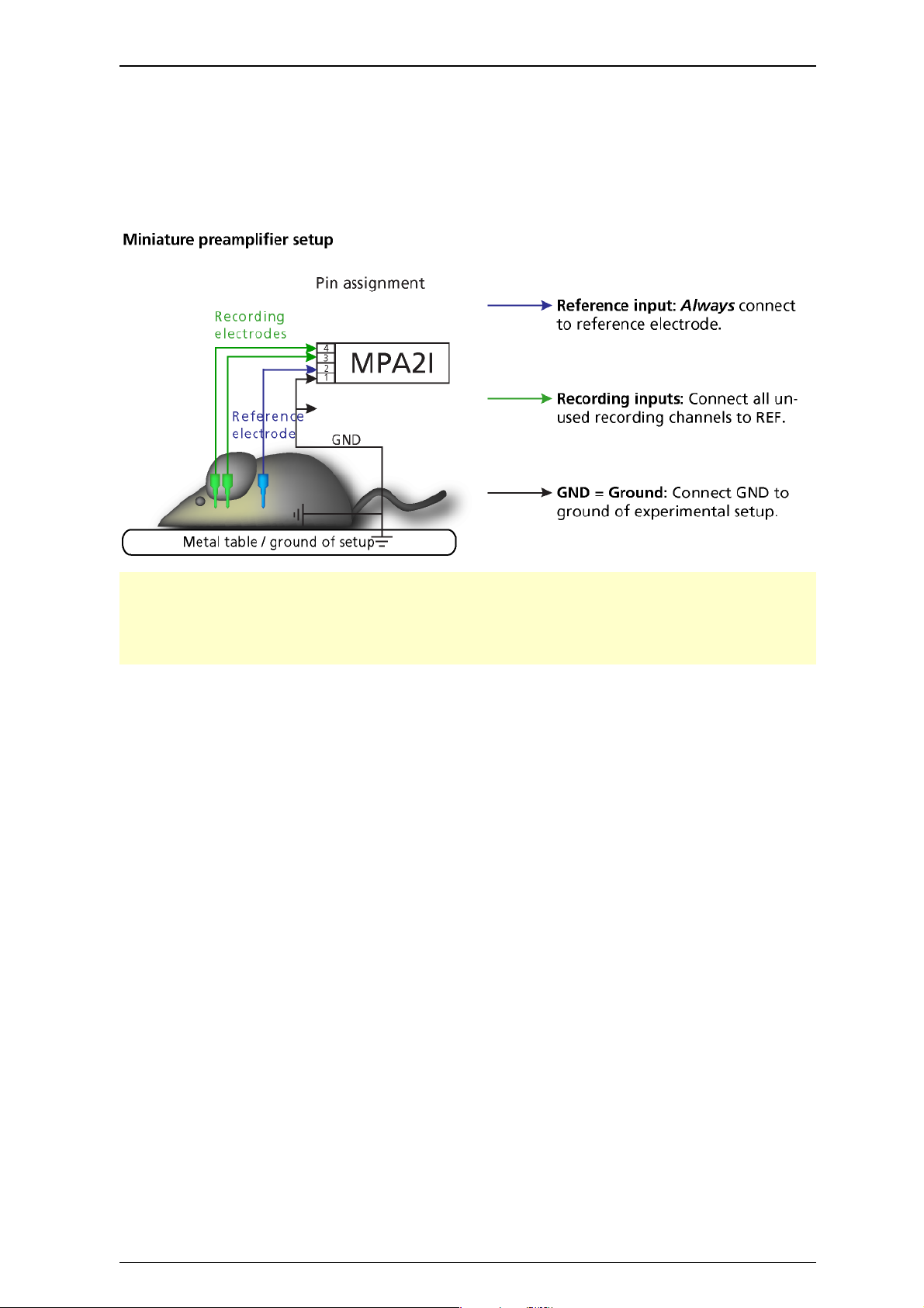
Important: It is important that the complete setup refers to a single common ground. The reference
input has always to be connected. It is recommended to use a reference electrode. However, if you
are not using a reference electrode, connect the reference input to ground (GND). Otherwise, noise
picked up by the reference input will be subtracted from the recording signals. This will either lead
to signal loss or to a very high noise level.
Ground the animal with a ground electrode of large surface area, for example, a liquid gel
adhesive electrode, that is connected to the ground of the setup, for example, a large metal table
or a Faraday cage, to avoid pickup of noise from the environment. The ground electrode is best
positioned in an electrically inactive region, not near muscle, nor heart, for example, at the belly.
Connect the GND input or the metal case of the miniature preamplifier to the common ground of
the setup. The GND input is internally connected to the metal case.
Connect the reference electrode to the reference input of the miniature preamplifier. Generally, a
reference electrode is inserted into non-active tissue of the experimental model. The reference electrode
should be identical to the recording electrode so that both electrodes see the same background noise.
This is necessary because despite the grounding, the animal’s body often has not exactly a potential of
zero, due to the electrode impedance, for example. The background noise is then subtracted from the
recording signal, increasing the signal to noise ratio. Please note that this may not work if the complete
setup is not properly grounded.
Connect the recording electrodes to the recording channels of the miniature preamplifier. You can
either use single electrodes or multitrodes with the miniature preamplifier. MCS provides adapters for
standard probes.
Connect all unused recording channels to the GND input or to the reference electrode, if ground
and reference are short circuited to avoid noise pickup. As the total amplifier gain generally lies in the
range of 1000, even very small noise signals may generate high noise signals.
4
Page 9

If you are not using a Faraday cage, it might be necessary to shield the complete setup with aluminum
foil or similar to prevent electrical interference from the outside. Connect the aluminum foil to the
ground of the setup (for example, the metal table).
Troubleshooting: If you observe problems with noise, check that the ground of the setup is connected
to exactly the same ground as the data acquisition computer. For example, connect the metal table
to the ground/earth wire of a free power outlet (of the same electrical system), as the computer is
generally connected to ground/earth via the power plug, too. Also, connect the data acquisition
computer’s metal case with a thick ground wire to the ground of the setup, for example, the
metal table, preferably with a 4 mm plug.
4 Service and Maintenance
Cleaning the Connectors
Warning: It is recommended to avoid the use of cleaning solutions to avoid corrosion. If a wet
cleaning is required, use distilled water. Make sure that only the connectors touch the liquid; do not
submerge the miniature preamplifier or the cable. Otherwise, you can fatally damage the electronics.
Clean the connectors with 70 % alcohol and cotton swabs from time to time.
If this does not provide satisfying results, insert only the connectors into a small beaker with acetone or
alcohol and treat them in an ultrasonic bath for 10 to 20 s. Air-dry the miniature preamplifier for about
5 min before use.
You can also clean the connectors with distilled water in an ultrasonic bath. Dry the connectors with
compressed air immediately after sonication and let the amplifier air dry for at least 6 h before use.
Sterilization
Warning: Do not autoclave or sterilize miniature preamplifiers by high heat (above 70 °C) or vapor.
The resin is not heat-stable and may deform under heat. Vapor can lead to a corrosion of the
electronics.
Miniature preamplifiers can be sterilized with standard methods that are not based on high heat or
vapor, for example, with 70 % ethanol, UV-light, or by thermal sterilization in an oven at 56 °C with
an incubation time of 8 hours.
5
Page 10
2-Channel Miniature Preamplifier Manual
5 Pin Layout
5.1 Power Supply
Supply voltage is applied to the output connector pins 8 and 15. The voltage source should supply
a stable noise-free voltage. Do not exceed the maximum voltage.
Pin 8: –3 V to –8 V
Pin 15: +3 V to +8 V
Warning: Do not mismatch the polarity of the power supply. A false connection may damage the unit.
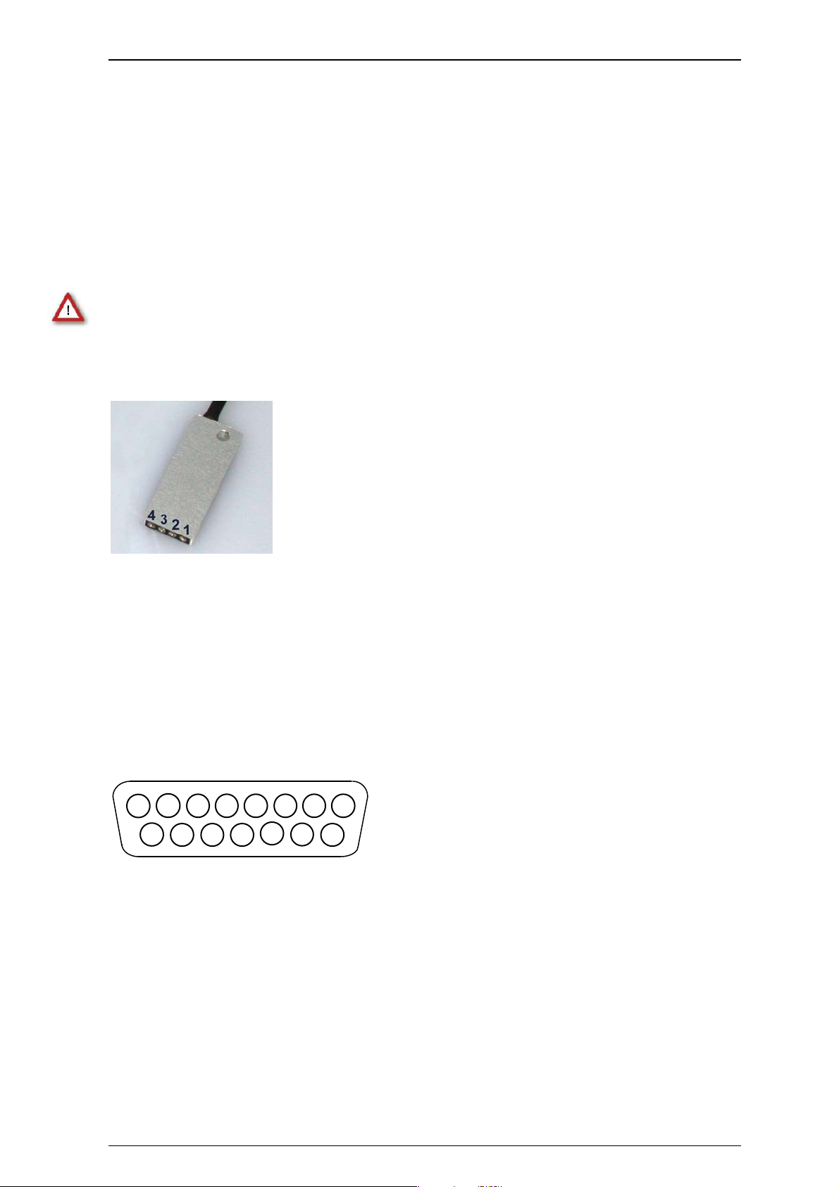
5.2 Input Connector
1 Ground (GND)
2 Reference input
3 Recording channel 1
4 Recording channel 2
5.3 Output Connector
(Male, Front View)
1
9
1 Ground (GND)
9 Signal ground*
2, 10 Recording channels 1 and 2
3 4 5 6 7 8
2
10 11 12
13
14
15
3, 11, 4, 12, 5, 13, 6, 14, 7 Ground (GND)
15 Positive supply voltage
8 Negative supply voltage
* = Connected to the ground of the amplifier. The signal ground is used as the reference
for the following filter amplifier.
6
Page 11

6 Contact Information
Local retailer
Please see the list of official MCS distributors on the MCS web site.
User forum
The Multi Channel Systems User Forum provides an excellent opportunity for you to exchange
your experience or thoughts with other users worldwide.
Mailing list
If you have subscribed to the mailing list, you will be automatically informed about new software
releases, upcoming events, and other news on the product line. You can subscribe to the list on
the contact form of the MCS web site.
Contact Information
www.multichannelsystems.com
7
Page 12

2-Channel Miniature Preamplifier Manual
7 Technical Specifications MPA8I
Operating temperature 0° C to 50° C
Storage temperature 0° C to 50° C
Relative humidity 10 % to 85 % non-condensing
Dimensions (W x D x H) 12 x 31 x 3 mm
Weight 1.3 g w/o cable and plug, 21 g with cable and plug
Length of the cable 1.5 m
Maximum tensile strength of cable 20 N
Input connector type Single-row precision sockets, 50 mil (1.27 mm)
grid pattern, for 0.35 to 0.45 mm round pins
Supply voltage ± 3 V to ± 8 V DC
Supply current < ± 2 mA, typically ± 1 mA
Number of input channels 2
Input voltage 500 mV (with respect to a supply voltage of 5 V)
Input impedance
Input noise < 1.5 μV
Noise density
Number of output channels 2
Output voltage = supply voltage
Output current max. = 10 mA
Output impedance
Bandwidth DC to 50 kHz
Gain 10
12
parallel to 10 pF
10
= 15 nV / Hz
e
n
0
(1 Hz to 5 kHz, inputs short-circuited)
RMS
8
 Loading...