

Page 1
Impedance Testing Device
MEA-IT Manual
Page 2

Information in this document is subject to change without notice.
No part of this document may be reproduced or transmitted without the express written
permission of Multi Channel Systems MCS GmbH.
While every precaution has been taken in the preparation of this document, the publisher
and the author assume no responsibility for errors or omissions, or for damages resulting
from the use of information contained in this document or from the use of programs and
source code that may accompany it. In no event shall the publisher and the author be liable
for any loss of profit or any other commercial damage caused or alleged to have been caused
directly or indirectly by this document.
© 2013 Multi Channel Systems MCS GmbH. All rights reserved.
Printed: 26. 09. 2013
Multi Channel Systems
MCS GmbH
Aspenhaustraße 21
72770 Reutlingen
Germany
Fon +49-71 21-90 92 5 - 0
Fax +49-71 21-90 92 5 -11
info@multichannelsystems.com
www.multichannelsystems.com
Microsoft and Windows are registered trademarks of Microsoft Corporation. Products that
are referred to in this document may be either trademarks and / or registered trademarks of
their respective holders and should be noted as such. The publisher and the author make no
claim to these trademark.
Page 3

Table of Contents
1 Introduction 1
1.1 About this Manual 1
1.2 Welcome to the Impedance Testing Device 2
2 Important Information and Instructions 3
2.1 Important Safety Advice 3
2.2 Guarantee and Liability 4
2.3 Operator's Obligations 4
3 Setting up the MEA-IT 5
3.1 Hardware 5
3.2 Installing the MEA-IT Software 7
3.3 Compatible Microelectrode Arrays 8
4 Impedance Measurements 11
4.1 Mounting the MEA 11
4.2 MEA-IT Software Controls 13
4.2.1 Introduction 13
4.2.2 Overview 14
4.2.3 Running a Measurement 20
5 Troubleshooting 23
5.1 Troubleshooting 23
5.2 Error Messages 23
5.3 Technical Support 24
6 Appendix 25
6.1 Technical Specifications 25
6.2 Contact Information 26
iii
Page 4

Page 5

1 Introduction
1.1 About this Manual
This manual comprises all important information about the first installation of the hardware
and software, and about the daily work with the instrument. It is assumed that you have already
a basic understanding of technical and software terms. No special skills are required to read this
manual.
If you are using the device for the first time, please read the important safety advice before
installing the hardware and software, where you will find important information about the
installation and first steps.
The printed manual and help are basically the same, so it is up to you which one you will use.
The help offers you the advantage of scrolling through the text in a non-linear fashion, picking
up all information you need, especially if you use the Index, and the Search function. If you
are going to read larger text passages, however, you may prefer the printed manual.
The device and the software are part of an ongoing developmental process. Please understand
that the provided documentation is not always up to date. The latest information can be found
in the help. Check also the MCS web site (www.multichannelsystems.com) for downloading up-todate manuals and help files.
1
Page 6
Impedance Testing Device MEA-IT Manual
1.2 Welcome to the Impedance Testing Device MEA-IT
The impedance testing device MEA-IT for microelectrode arrays with 60 electrodes allows an easy
monitoring of MEA electrode impedances. The measurement process is controlled by the software
MEA-IT. On a virtual MEA layout the impedance of each electrode is displayed in an intuitive color
code.
It is possible to save the data after each measurement to a database file and to export the data
in ASCII format . This way you can monitor the development of each single electrode' s impedance
over the entire life span of each microelectrode array.
Based on this information the user can, for example, decide whether a MEA chip can be put to
further use or should be discarded, or if a specific surface treatment or coating has any relevant
influence on the electrode impedance.
2
Page 7

2 Important Information and Instructions
2.1 Important Safety Advice
Warning: Make sure to read the following advice prior to install or to use the device and the
software. If you do not fulfill all requirements stated below, this may lead to malfunctions or
breakage of connected hardware, or even fatal injuries.
Warning: Obey always the rules of local regulations and laws. Only qualified personnel should
be allowed to perform laboratory work. Work according to good laboratory practice to obtain
best results and to minimize risks.
The product has been built to the state of the art and in accordance with recognized safety
engineering rules. The device may only
be used for its intended purpose;
be used when in a perfect condition.
Improper use could lead to serious, even fatal injuries to the user or third parties and damage
to the device itself or other material damage.
Warning: The device and the software are not intended for medical uses and must not
be used on humans.
Malfunctions which could impair safety should be rectified immediately.
High Voltage
Electrical cords must be properly laid and installed. The length and quality of the cords must
be in accordance with local provisions.
Only qualified technicians may work on the electrical system. It is essential that the accident
prevention regulations and those of the employers' liability associations are observed.
Each time before starting up, make sure that the mains supply agrees with the specifications
of the connected computer.
Check the USB cord for damage each time the site is changed. Damaged cords should be replaced
immediately and may never be reused.
Check the leads for damage. Damaged leads should be replaced immediately and may never
be reused.
Do not try to insert anything sharp or metallic into the vents or the case.
Liquids may cause short circuits or other damage. Keep the device and the power cords always
dry. Do not handle it with wet hands.
Requirements for the installation
Make sure that the device is not exposed to direct sunlight. Do not place anything on top of
the device, and do not place it on top of another heat producing device. Never cover the vents,
not even partially, so that the air can circulate freely. Otherwise, the device may overheat.
3
Page 8

Impedance Testing Device MEA-IT Manual
2.2 Guarantee and Liability
The General conditions of sale and delivery of Multi Channel Systems MCS GmbH always apply.
The operator will receive these no later than on conclusion of the contract.
Multi Channel Systems MCS GmbH makes no guarantee as to the accuracy of any and all tests
and data generated by the use of the device or the software. It is up to the user to use good
laboratory practice to establish the validity of his findings.
Guarantee and liability claims in the event of injury or material damage are excluded when
they are the result of one of the following.
Improper use of the device.
Improper installation, commissioning, operation or maintenance of the device.
Operating the device when the safety and protective devices are defective and/or inoperable.
Non-observance of the instructions in the manual with regard to transport, storage, installation,
commissioning, operation or maintenance of the device.
Unauthorized structural alterations to the device.
Unauthorized modifications to the system settings.
Inadequate monitoring of device components subject to wear.
Improperly executed and unauthorized repairs.
Unauthorized opening of the device or its components.
Catastrophic events due to the effect of foreign bodies or acts of God.
2.3 Operator's Obligations
The operator is obliged to allow only persons to work on the device, who
are familiar with the safety at work and accident prevention regulations and have been
instructed how to use the device;
are professionally qualified or have specialist knowledge and training and have received
instruction in the use of the device;
have read and understood the chapter on safety and the warning instructions in this manual
and confirmed this with their signature.
It must be monitored at regular intervals that the operating personnel are working safely.
Personnel still undergoing training may only work on the device under the supervision
of an experienced person.
4
Page 9
3 Setting up the MEA-IT
3.1 Hardware
The MEA-IT is a very compact and portable device for measuring electrode impedances
on microelectrode arrays (MEA) with MEA-IT software.
The measurements are transmitted to the connected computer via universal serial bus
(USB 2.0 Full Speed). Thus, it is possible to use any computer as a data acquisition computer,
also a laptop.
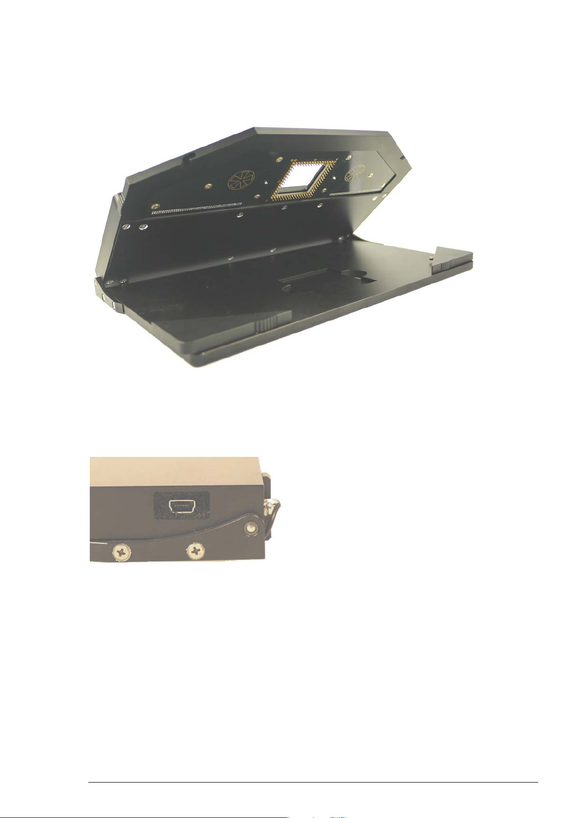
The device does not need an own power supply. Just connect it to an USB port of the
data acquisition computer and the blue LED on the right side of the front panel lights up.
The USB connector is located on the side panel of the device.
5
Page 10

Impedance Testing Device MEA-IT Manual
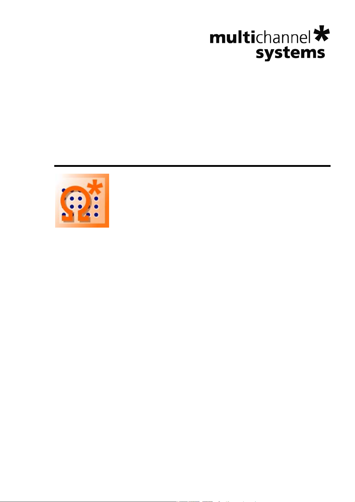
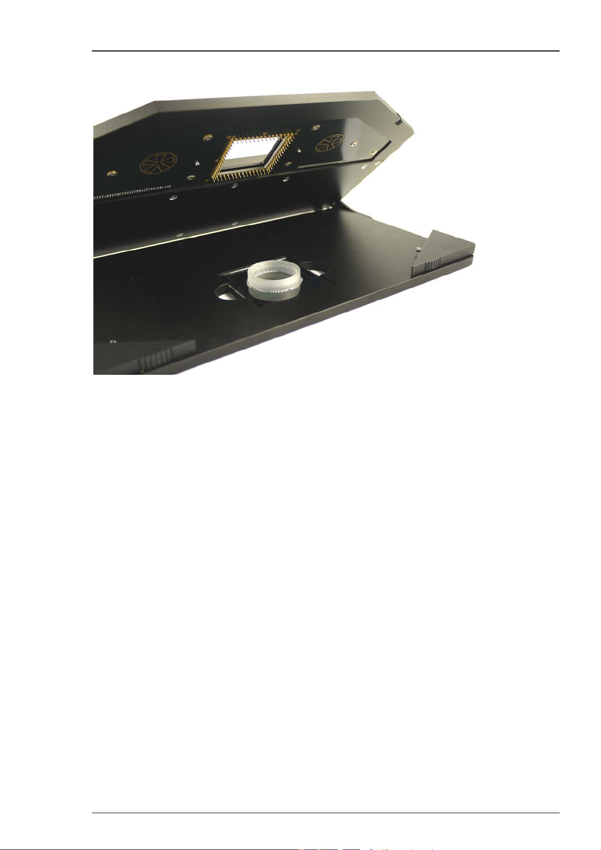
The two triangular front edges of the device can be moved outwards and inwards to open
and close the MEA-IT device, respectively.
Two sockets are provided to connect an Ag/AgCl ground electrode.
Important: You always have to connect an Ag/AgCl silver wire even though you like to measure
a MEA with internal reference electrode. Otherwise the impedances are too high.
Important: Please wait approximately fifteen minutes after filling the MEA dish with conducting
solution before measuring the electrodes!
6
Page 11

3.2 Installing the MEA-IT Software
System requirements
Software: One of the following Microsoft Windows ® operating systems is required XP
(Service Pack SP 3), Vista or Windows 7 (32 or 64 bit), English and German versions supported
with the NT file system. Other language versions may lead to software errors.
Hardware: You can operate the MEA-IT device with any computer with an USB 2.0 port.
Important: Please make sure that you have full control over your computer as an administrator
for installation the MEA-IT software. Otherwise, it is possible that the installed software does
not work properly. For operating the software it is not necessary to have administrator rights.
Installing the MEA-IT Software
Start the MEA-IT.exe and follow the instructions of the installation wizard.
Setting up the MEA-IT
The software requires the Microsoft NET Framework 4.0. The installer automatically checks
if the required components are already installed. If not they are installed either from the
installation media or from the internet.
Warning: The installation of the NET Framework might take a few minutes and
might, depending on the operation system, also require a reboot of the computer.
After the NET Framework is installed, the MEA-IT software and the actual driver are installed
automatically.
7
Page 12

Impedance Testing Device MEA-IT Manual
3.3 Compatible Microelectrode Arrays
Currently, the MEA-IT is available for MEAs with 60 electrodes only. Contacting units for different
layouts are under development. Please contact Multi Channel Systems MCS GmbH for detailed
information.
Each MEA is classified by its type and its individual serial number, which is engraved on the back
side of the MEA.
The name of the specific MEA defines its parameters: 100/10iR-Ti, for example.
The first number is the distance between the electrodes in the layout grid. The number after the
slash is the diameter of the recording electrodes. Ti (titanium nitride) and ITO (Indium tin oxide)
are materials for electrodes and / or tracks and / or contact pads. The character "iR" indicates
whether the MEA has an internal reference or not.
Positioning the MEA
Important: MEAs are not symmetrical! That is, why the writing (for example NMI, LEITER, MEA
type) on the MEA chip should be on the right side viewed from the front of the MEA-IT device.
MEAs with one big internal reference electrode should be placed with reference electrode to
the left side in the MEA-IT device. Otherwise, the MEA layout will not match with the pin layout
of the MEA-IT device.
When placing a special MEA into the amplifier, for example HighDense MEA, 4Q1000 MEA
or HexaMEA, please make sure that the orientation of the MEA is correct, respectively.
8
Page 13

Setting up the MEA-IT
Table of microelectrode arrays, currently available for impedance testing device MEA-IT.
Standard MEA 8 x 8 layout 100/10-Ti
100/10-ITO
200/10iR-ITO
200/10iR-Ti
200/10-ITO
200/10-Ti
200/30-Ti
200/30iR-ITO
200/30iR-Ti
200/30-ITO
Stimulation MEA 200/30-Ti-stim
200/30-ITO-stim
6 Well MEA 6wellMEA200/30iR-Ti
HighDense MEA HD30/10-ITO
HD30/10iR-ITO
Hexa MEA HexaMEA-ITO
HexaMEA-Ti
HexaMEA40/10iR-ITO
Thin MEA ThinMEA100/10-ITO
ThinMEA200/30iR-ITO
ThinMEA30/10-ITO
MEA 6 x 10 layout 500/10iR-Ti
500/30iR-Ti
Economical MEA
EcoMEA
EcoMEA-Glass
4 Quadrant MEA 4QMEA1000iR-Ti
9
Page 14

Page 15

4 Impedance Measurements
4.1 Mounting the MEA
Open the upper part of the device by moving the triangular edges of the lid outwards. The lid
swings open. Before inserting the MEA note its layout and the individual serial number. Please
see chapter "Compatible Microelectrode Arrays". Insert the MEA carefully into the provided area
in the middle. Make sure that the MEA is correct orientated. Close the device by pressing down
the lid and moving the triangular edges of the lid inwards.
Positioning the MEA
Important: MEAs are not symmetrical! Therefore, the small writing (for example NMI, LEITER,
MEA type) on the MEA chip should be on the right side viewed from the front of the MEA-IT
device. MEAs with one big internal reference electrode should be placed with reference
electrode to the left side in the MEA-IT device. Otherwise, the MEA layout will not match
with the pin layout of the MEA-IT device.
When placing a special MEA into the amplifier, for example HighDense MEA, 4Q1000 MEA
or HexaMEA, please make sure that the orientation of the MEA is correct, respectively.
11
Page 16
Impedance Testing Device MEA-IT Manual
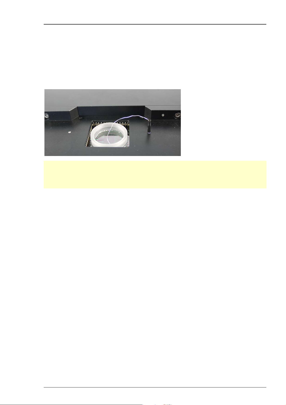
Grounding the MEA
Fill the MEA dish with a conducting solution, usually PBS (phosphate buffered saline) or
with ACSF (artificial cerebral spinal fluid for rats and mice). The impedance of an electrode
also depends on the hydrophilic properties of the electrode. If an electrode is hydrophobic,
the measured impedance will be too high.
Ground the MEA with the included Ag/AgCl pellet. There are two identical sockets provided
to connect the ground electrode. An external ground electrode is also necessary for MEAs
with internal reference electrode.
Important: Please wait approximately fifteen minutes after filling the MEA dish with conducting
solution before measuring the electrodes!
Important: You always have to connect an Ag/AgCl silver wire even though you measure a MEA
with internal reference electrode. Otherwise the impedances will be out of range.
The reference electrode of a MEA with internal reference is connected to pin 15, the ground pin
in MEA-Systems but not in MEA-IT. In MEA-IT-Systems the electrode connected to pin 15 will be
measured just as all others. That is why you always need the silver wire as an external reference
point for grounding the MEA-IT-System during measurements.
12
Page 17
4.2 MEA-IT Software Controls
4.2.1 Introduction
The MEA-IT software controls the impedance measurements with the MEA-IT device. Each MEA
is identified by its individual serial number, and all measurements for each MEA are stored in
a database file. A current impedance measurement can be compared to any previous one stored
in the database in order to identify changes in electrode impedance over time. It is also possible
to compare the measured impedances to reference values for any individual electrode type or
to highlight outliers. On a virtual MEA layout the impedance of each electrode is displayed in
an intuitive color code. This allows judging the status of a MEA at a single glance.
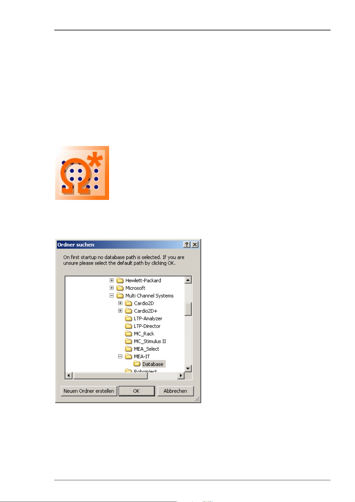
After installing the 'MEA-IT software you can start the program with a double-click on the
program icon.
Impedance Measurements
When starting the MEA-IT software for the first time you have to select the path for the database
file. The following dialog will come up.
Either accept the default path or select a different folder for the impedance measurement
database.
13
Page 18
Impedance Testing Device MEA-IT Manual
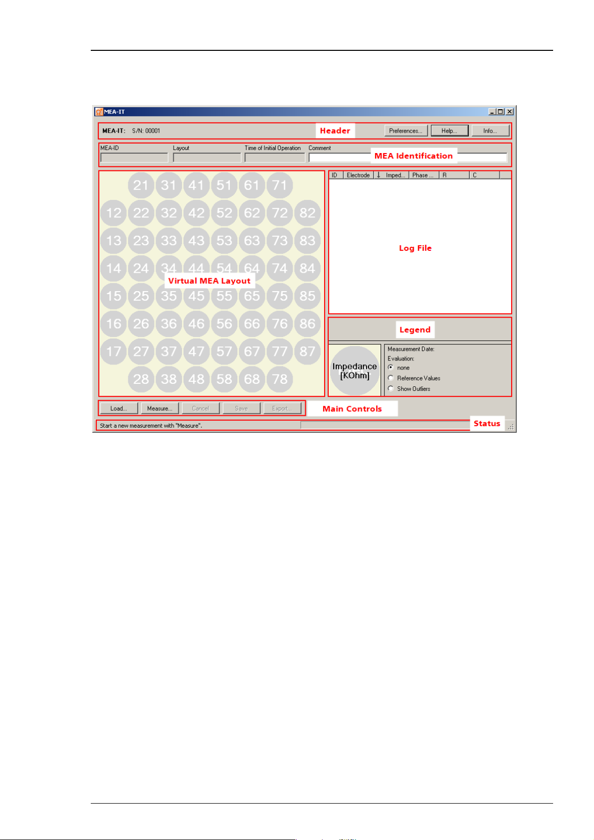
4.2.2 Overview
The MEA-IT main window opens. See below for an overview of the MEA-IT software control.
14
Page 19

Impedance Measurements
Header
In the header the serial number S/N of the MEA-IT device is displayed. You can
find the serial number additionally on the rear panel of the device or in “Info”.
Click the "Preferences" button. The following dialog has three tabs.
Under "Database" the user can change the selected path for the database file.
Click the "Export" button.
It is possible to select the layout for the ASCII export.
15
Page 20
Impedance Testing Device MEA-IT Manual
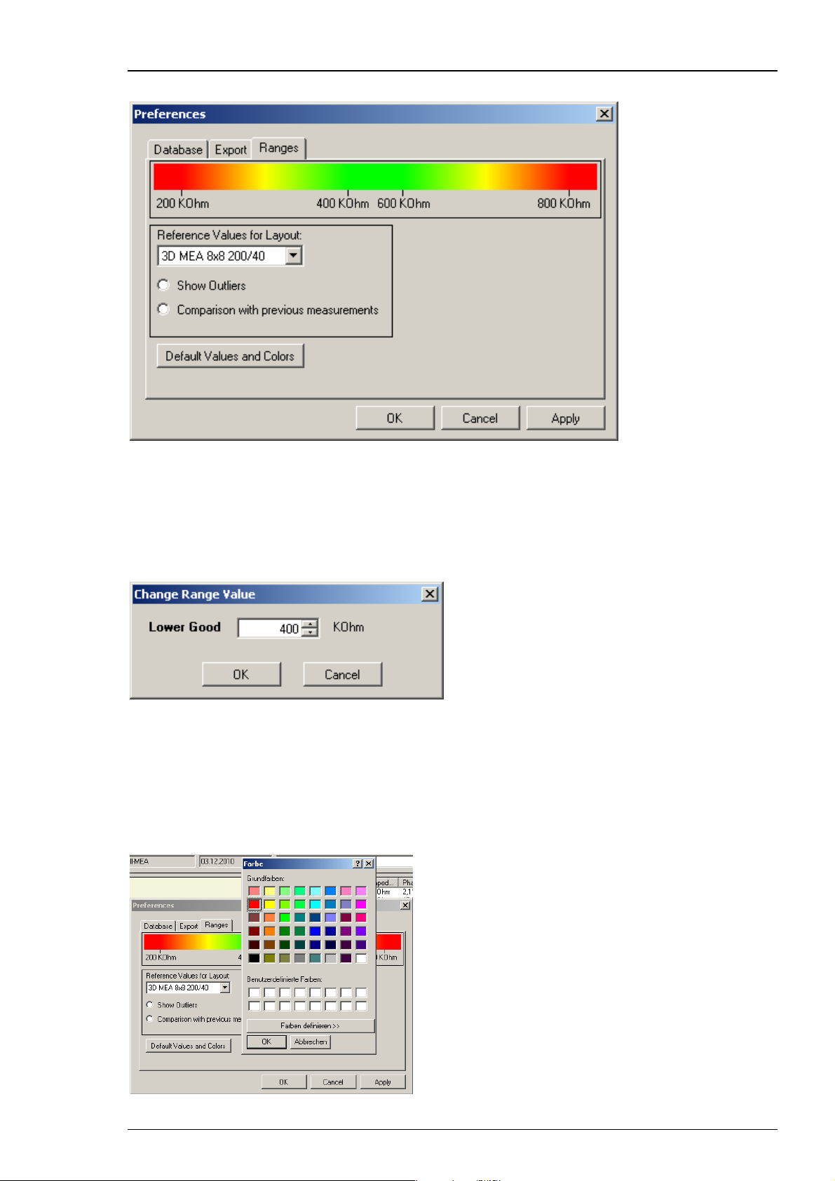
Click the "Ranges" button.
In the "Ranges" tab, the default settings for the evaluation of a MEA can be changed.
The MEA-IT software uses default reference values to evaluate whether a measured
impedance is all right or out of the acceptable range for the selected electrode type.
This evaluation is displayed in an intuitive color code.
To change the default reference parameters, select a layout and click on the reference value
you want to modify.
Enter the new value in the pop up window. To restore the default values,
use the “Default Values and Colors” button.
The relative limits for outliers and the comparison with previous measurements can be changed
in similar way.
It is also possible to change the default colors. Right-click on a color of the color bar and you can
select user defined colors.
16
Page 21
Impedance Measurements
Click the "Help" button of the header for using the online help.
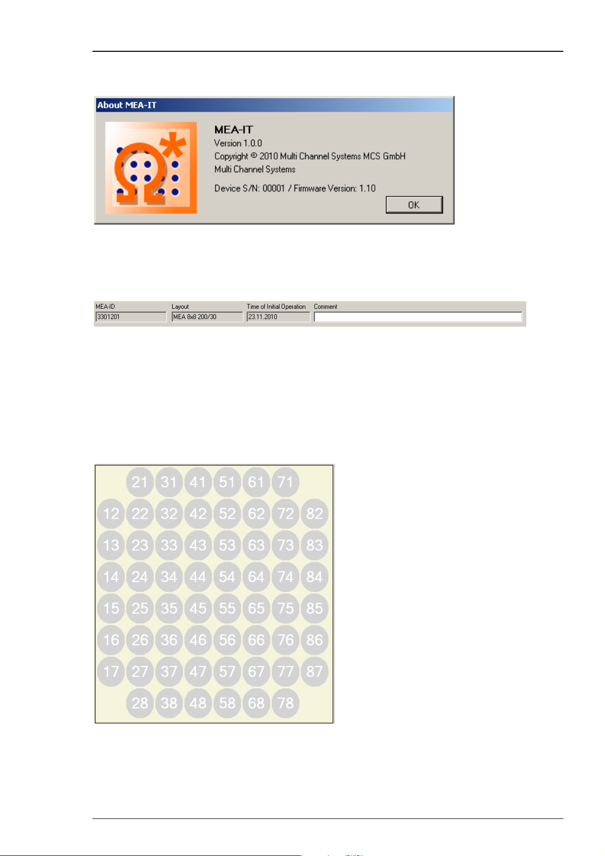
Click the "Info" button of the header.
The "About MEA-IT" dialog shows the serial number of the MEA-IT device and the actual
MEA-IT software and firmware version.
MEA Identification Line
The MEA Identification line shows the “Layout” and the individual "MEA-ID", usually
the serial number engraved on the back side of each MEA. These parameters can be
entered in the "Select MEA" dialog at the beginning of each measurement (please see below).
The "Time of Initial Operation" is a date that should be entered at the first measurement
of each MEA. It will be saved with the MEAs database file and helps the user to keep track
on the age of an array. A "Comment" can be added at any time before and during the
measurement. The comment will also be saved in the measurement file.
Virtual MEA Layout
The virtual MEA layout shows the MEA electrodes in grey color, labeled with their electrode
name in the layout grid, selected in the "Select MEA" dialog (please see below). The numbering
of the MEA electrodes in the display corresponds with the layout described in the MEA datasheet.
Measured impedance values are shown in black letters on each electrode.
17
Page 22

Impedance Testing Device MEA-IT Manual
Main Controls
The main control buttons allow to "Load" an old measurement and "Save" the current one
to the database. The "Measurement" and "Cancel" buttons start and interrupt the impedance
measurement. With the "Export" function, the results of a current or loaded measurement can
be exported in ASCII format. The layout of the ASCII file can be selected in the "Preferences"
dialog.
Log File
Next to the virtual MEA layout the log file window also displays the impedance measurement
values, as well as some additional parameters. There are six columns: ID = Hardware ID,
Electrode = electrode name, Impedance, Phase Shift, R = resistance, and C = capacitance.
You can click into the header of each column to sort the values of this column. If the arrow
points up, the column starts with the smallest values. You can click on the header again and
the arrow and the values will turn around and the column starts with the largest values.
The column "ID" displays the hardware ID of the MEA electrodes in the sequence of
measurement. The column "Electrode" displays the electrode name in the layout grid.
Depending on the MEA type, the name can consist of either only numbers or letters and numbers.
The "Impedance" is measured in units of kilo Ohm. It’s the same value that is displayed
in the virtual MEA Layout. The "Phase Shift" is measured in degrees. The values of phase
shift and impedance are used to calculate the values of the resistor and the capacitor. The "R"
Resistance values are shown in kilo Ohm. The "C" Capacitance values are shown in nano Farad.
18
Page 23

Impedance Measurements
Legend
The “Legend” describes what you see in the virtual MEA layout: The color coded MEA electrodes
with the value of the measured impedance in black letters in the front, and the electrode names
in white letters in the back.
To evaluate a MEA, you can compare the measured impedances to individual reference values
for each electrode type. Good and bad electrodes will be color coded according to the limits
shown in the legend. It is also possible to highlight outliers. You can change the default limits
in the “Preferences” dialog.
Alternatively, the user can compare the current measurement to any previous measurement
from the same MEA present in the database file. Use the tick boxes or the drop down menu to
select the reference measurement. The date of the reference measurement will appear in the
upper right corner of the legend.
Status Line
The status line will indicate the actual status of the software and suggest a next step, respectively.
19
Page 24

Impedance Testing Device MEA-IT Manual
4.2.3 Running a Measurement
Note the serial number and type of the MEA, and mount it in the correct orientation
in the MEA-IT device (please read chapter "Mounting the MEA").
Open the MEA-IT software and click the button "Measure" in "Main Controls" to start
a measurement. The "Select MEA" dialog appears.
Please type the serial number of the MEA into the "MEA-ID" in the drop down box.
The program will save the ID and you can select it from the drop down menu, when
measuring the same MEA again.
Please select a MEA "Layout" from the drop down menu. This is important, because the
diameter of an electrode has a major influence on its impedance: Smaller electrodes have
a higher impedance than bigger electrodes. For example, electrodes with 30 μm have an
impedance of about 30 - 50 kOhm and smaller electrodes with a diameter of 10 μm have
an impedance of about 250 - 400 kOhm. The impedance of an electrode also depends on
the hydrophilic properties of the electrode. If an electrode is hydrophobic, the measured
impedance will be too high.
The selection in “Layout” also defines the appearance of the virtual MEA layout. If the MEA
is already present in the database the "Layout" and the "Time of Initial Operation" will
be set automatically.
When testing a MEA with internal reference (iR), please activate the check box "Internal
Reference". The reference electrode is much bigger than the recording electrodes, that is
why the impedance should be very low. The MEA-IT software will therefore use different
reference values to evaluate the reference electrodes than the regular recording electrodes.
The "Time of Initial Operation" is the date that should be entered at the first measurement
of each MEA. It will be saved with the MEAs database file and helps the user to keep track on
the age of an array. The content of the "Comment" window will also be saved together with
the measurements.
The drop down menus "MEA-ID" and "Layout" are labeled with an asterisk *. They are required
to start a measurement.
20
Page 25

Click "OK" to start the measurement.
Impedance Measurements
The electrodes are measured one by one and the exact values of the measurements are written
in black letters inside the electrodes, and also in the log file in column "Impedance". The color
code is activated only when comparing with previous measurements or when the check box
“Show Outliers” is enabled. Otherwise the color of the electrodes remains grey.
Click the "Cancel" button to stop a measurement.
Click the "Save" button to save the measurement file in the data base.
Important: You have to actively save a measurement to archive the file in the database!
With the "Export" function, the results of a current or loaded measurement can be exported
in ASCII format. The layout of the ASCII file can be selected in the "Preferences" dialog.
The current measurement can be evaluated or compared to previous measurements of the
same MEA. Evaluation results are shown as color code in the virtual MEA display. An impedance
measurement can either be compared to reference values for a given electrode type, or outliers
in the array can be highlighted, please see above.
The "Compare to" function allows comparing the current measurement with any previous
measurement for that MEA which is present in the database file.
21
Page 26

Impedance Testing Device MEA-IT Manual
When comparing previous measurements with actual measurements, the impedance of the older
measurement is displayed in the upper right corner of each electrode in the Virtual MEA Layout.
It is possible to switch between the different evaluation and comparison options without running
a new measurement.
With all options, a green color indicates no relevant difference to reference values, previous
measurements or other electrodes, while yellow or red colors indicate a value out of the
acceptable limits. The default limits are suggested by the MEA manufacturer, but they can
be modified by the user under "Preferences".
.
22
Page 27
5 Troubleshooting
5.1 Troubleshooting
Most problems occur seldom and only under specific circumstances. In most cases, it is only a minor
problem that can be easily avoided or solved.
If the problem persists, please contact your local retailer. The highly qualified staff will be glad to
help you. Please inform your local retailer as well, if other problems that are not mentioned in this
documentation occur, even if you have solved the problem on your own. This helps other users,
and it helps MCS to optimize the instrument and the documentation.
Please pay attention to the safety and service information in chapter "Important Safety Advice".
Multi Channel Systems has put all effort into making the product fully stable and reliable, but
like all high-performance products, it has to be handled with care.
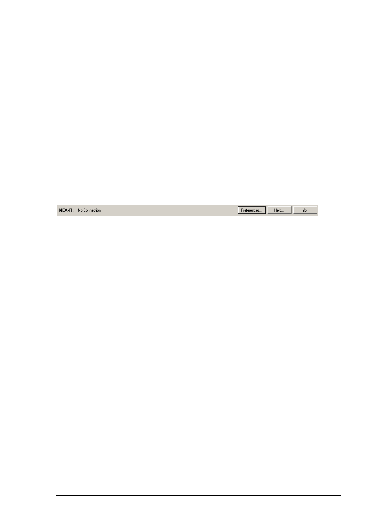
5.2 Error Messages
If the MEA-IT device and the data acquisition computer are not connected the error massage
"No Connection" appears in the header of the main window. At the same time the button
"Measurement" below the virtual MEA layout turns to "Load".
Possible causes:
? The blue power LED is not lightning. The supply power via computer is not connected
or there is a technical problem with the instrument.
Check the power source and the cable connections. If this does not solve the problem,
please contact your local retailer for support.
? The power LED is lighting. The USB port might not support USB 2.0 or might not be working.
Check the USB port. Only Full Speed USB 2.0 ports can be used. Try another USB 2.0 port.
If the problem is solved you can click the "Load" button to restart the measurements.
The "Select MEA" dialog will appear, you can fill in the required fields and start up again.
23
Page 28

Impedance Testing Device MEA-IT Manual
5.3 Technical Support
Please read the "Troubleshooting" part of the manual or help first. Most problems are caused
by minor handling errors. Contact your local retailer immediately if the cause of the trouble
remains unclear. Please understand that information on your hardware and software
configuration is necessary to analyze and finally solve the problem you encounter.
If you have any question or if any problem occurs that is not mentioned in this documentation,
please contact your local retailer. The highly qualified stuff will be glad to help you.
Please keep information on the following at hand
Description of the error (the error message text or any other useful information) and of the
context in which the error occurred. The more information on the actual situation you can
provide, the easier it is to track the problem.
The serial number of the device. You will find it on the bottom side of the main unit,
and in the header of the main window of MEA-IT software
The software version you are currently using. Click on the "Info" button in the header
of the main window of MEA-IT software. The displayed "About" dialog box shows the
software version number.
The operating system and service pack number on the connected computer.
The hardware configuration (microprocessor, frequency, main memory, hard disk)
of the connected computer. This information is especially important if you have
modified the computer or installed new hard- or software recently.
24
Page 29

6 Appendix
6.1 Technical Specifications
The MEA-IT-System is a device for impedance testing of microelectrode arrays.
Warning: The device may only be used together with microelectrode arrays from
Multi Channel Systems MCS GmbH, and only for the specified purpose. Damage of
the device and even fatal injuries can result from improper use. Do not open the data
acquisition box and do not change hardware configuration as it could lead to improper
behavior of the system.
General characteristics
Operating temperature 10 °C to 50 °C
Storage temperature 0 °C to 50 °C
Relative humidity 10 % to 85 %, non-condensing
Dimensions (W x D x H) 250 mm x 140 mm x 25 mm
Weight 1100 g
Number of channels 60
Measurement range
Test signal 100 mV, 1 kHz Sinus
Accuracy 5 %
Power supply USB powered
PC interface USB 2.0
5 k to 2 M
Software
Operating system Microsoft Windows ® 7 (32 or 64 bit), XP or Vista
MEA-IT program Version 1.0.0 and higher
with NTFS, English and German version supported
25
Page 30

Impedance Testing Device MEA-IT Manual
6.2 Contact Information
Local retailer
Please see the list of official MCS distributors on the MCS web site.
User forum
The Multi Channel Systems User Forum provides the opportunity for you to exchange
your experience or thoughts with other users worldwide.
Mailing list
If you have subscribed to the Mailing List, you will be automatically informed about new software
releases, upcoming events, and other news on the product line. You can subscribe to the list on
the contact form of the MCS web site.
www.multichannelsystems.com
26
 Loading...