

Page 1

MEA Amplifier with Blanking Circuit
for Inverse Microscopes
Page 2

Information in this document is subject to change without notice.
No part of this document may be reproduced or transmitted without the express written
permission of Multi Channel Systems MCS GmbH.
While every precaution has been taken in the preparation of this document, the publisher
and the author assume no responsibility for errors or omissions, or for damages resulting
from the use of information contained in this document or from the use of programs and
source code that may accompany it. In no event shall the publisher and the author be liable
for any loss of profit or any other commercial damage caused or alleged to have been caused
directly or indirectly by this document.
© 2012 Multi Channel Systems MCS GmbH. All rights reserved.
Printed: 05. 11. 2012
Multi Channel Systems
MCS GmbH
Aspenhaustraße 21
72770 Reutlingen
Germany
Fon +49-71 21-90 92 5 - 0
Fax +49-71 21-90 92 5 -11
info@multichannelsystems.com
www.multichannelsystems.com
Microsoft and Windows are registered trademarks of Microsoft Corporation. Products that
are referred to in this document may be either trademarks and/or registered trademarks of
their respective holders and should be noted as such. The publisher and the author make
no claim to these trademark.
Page 3

Table of Contents
1 Introduction 1
1.1 About this Manual 1
1.2 Terms of Use for the Program 1
1.3 Limitation of Liability 1
2 Important Information and Instructions 3
2.1 Operator's Obligations 3
2.2 Guarantee and Liability 3
2.3 Important Safety Advice 4
3 First Use of the MEA Amplifier 5
3.1 Welcome to the MEA Amplifier 5
3.2 Installing the Software 6
3.3 MEA_Select Program 7
3.4 Setting Up and Connecting the MEA Amplifier 10
4 First Tests and Tutorial 13
4.1 First Functional Tests 13
4.2 General Performance / Noise Level 13
4.3 Computer Connection 15
4.4 Stimulation and Recording 15
4.4.1 Operating multiple MEA Amplifiers with one STG16
5 Operating the MEA Amplifier 23
5.1 Signal Amplification and Filters 23
5.2 Temperature Control 25
5.3 Mounting the MEA Probe and Grounding the Bath 26
5.4 Grounding Defective Electrodes 28
5.5 Stimulation 30
5.6 Stimulus Artifact Suppression (Blanking) 33
5.7 Examples with Different MEA Types 36
5.8 Service and Maintenance 40
iii
Page 4

MEA Amplifier with Blanking Circuit for Inverse Microscopes
6
Troubleshooting 41
6.1 About Troubleshooting 41
6.2 Error Messages 41
6.3 Noise on Single Electrodes 41
6.4 Unsteady Baseline 42
6.5 Artifacts on All Channels 43
6.6 Unpredictable Noise and Artifacts 44
6.7 Liquid Spilled onto Amplifier 45
6.8 Technical Support 46
7 Appendix 47
7.1 Technical Specifications 47
7.1.1 Pin and MEA Layout 47
7.1.2 MEA1060-Inv-BC 49
7.1.3 FA60S-BC 50
7.2 Contact Information 51
7.3 Ordering Information 52
8 Index 57
iv
Page 5

1 Introduction
1.1 About this Manual
This manual comprises all important information help the first installation of the hardware and
software, and help the daily work with the instrument. It is assumed that you have already a basic
understanding of technical and software terms. No special skills are required to read this manual.
If you are using the device for the first time, please read the important safety advice before
installing the hardware and software, where you will find important information help the
installation and first steps.
The printed manual and help are basically the same, so it is up to you which one you will use.
The help offers you the advantage of scrolling through the text in a non-linear fashion, picking
up all information you need, especially if you use the Index, and the Search function.. If you are
going to read larger text passages, however, you may prefer the printed manual.
The device and the software are part of an ongoing developmental process. Please understand
that the provided documentation is not always up to date. The latest information can be found
in the help. Check also the MCS web site (www.multichannelsystems.com) for downloading up-todate manuals and help files.
1.2 Terms of Use for the Program
You are free to use the program for its intended purpose. You agree that you will not decompile,
reverse engineer, or otherwise attempt to discover the source code of the software.
1.3 Limitation of Liability
Multi Channel Systems MCS GmbH makes no guarantee as to the accuracy of any and all tests
and data generated by the use the software. It is up to the user to use good laboratory practice
to establish the validity of his findings.
To the maximum extent permitted by applicable law, in no event shall Multi Channel Systems
MCS GmbH or its suppliers be liable for any special, incidental, indirect, or consequential damages
whatsoever (including, without limitation, injuries, damages for data loss, loss of business profits,
business interruption, loss of business information, or any other pecuniary loss) arising out of the
use of or inability to use the program or the provision of or failure to provide Support Services,
even if Multi Channel Systems MCS GmbH has been advised of the possibility of such damages.
1
Page 6

Page 7

2 Important Information and Instructions
2.1 Operator's Obligations
The operator is obliged to allow only persons to work on the device, who
are familiar with the safety at work and accident prevention regulations and have been
instructed how to use the device;
are professionally qualified or have specialist knowledge and training and have received
instruction in the use of the device;
have read and understood the chapter on safety and the warning instructions in this manual
and confirmed this with their signature.
It must be monitored at regular intervals that the operating personnel are working safely.
Personnel still undergoing training may only work on the device under the supervision of
an experienced person.
2.2 Guarantee and Liability
The General conditions of sale and delivery of Multi Channel Systems MCS GmbH always apply.
The operator will receive these no later than on conclusion of the contract.
Multi Channel Systems MCS GmbH makes no guarantee as to the accuracy of any and all tests
and data generated by the use of the device or the software. It is up to the user to use good
laboratory practice to establish the validity of his findings.
Guarantee and liability claims in the event of injury or material damage are excluded when
they are the result of one of the following.
Improper use of the device.
Improper installation, commissioning, operation or maintenance of the device.
Operating the device when the safety and protective devices are defective and/or inoperable.
Non-observance of the instructions in the manual with regard to transport, storage, installation,
commissioning, operation or maintenance of the device.
Unauthorized structural alterations to the device.
Unauthorized modifications to the system settings.
Inadequate monitoring of device components subject to wear.
Improperly executed and unauthorized repairs.
Unauthorized opening of the device or its components.
Catastrophic events due to the effect of foreign bodies or acts of God.
3
Page 8
MEA Amplifier with Blanking Circuit for Inverse Microscopes
2.3 Important Safety Advice
Warning: Make sure to read the following advice prior to install or to use the device and the
software. If you do not fulfill all requirements stated below, this may lead to malfunctions or
breakage of connected hardware, or even fatal injuries.
Warning: Obey always the rules of local regulations and laws. Only qualified personnel should
be allowed to perform laboratory work. Work according to good laboratory practice to obtain
best results and to minimize risks.
The product has been built to the state of the art and in accordance with recognized safety
engineering rules. The device may only
be used for its intended purpose;
be used when in a perfect condition.
Improper use could lead to serious, even fatal injuries to the user or third parties and damage
to the device itself or other material damage.
Warning: The device and the software are not intended for medical uses and must not be
used on humans.
Malfunctions which could impair safety should be rectified immediately.
High Voltage
Electrical cords must be properly laid and installed. The length and quality of the cords must
be in accordance with local provisions.
Only qualified technicians may work on the electrical system. It is essential that the accident
prevention regulations and those of the employers' liability associations are observed.
Each time before starting up, make sure that the mains supply agrees with the specifications
of the product.
Check the power cord for damage each time the site is changed. Damaged power cords should
be replaced immediately and may never be reused.
Check the leads for damage. Damaged leads should be replaced immediately and may never
be reused.
Do not try to insert anything sharp or metallic into the vents or the case.
Liquids may cause short circuits or other damage. Keep the device and the power cords always
dry. Do not handle it with wet hands.
Requirements for the installation
Make sure that the device is not exposed to direct sunlight. Do not place anything on top of
the device, and do not place it on top of another heat producing device. Never cover the device,
not even partially, so that the air can circulate freely. Otherwise, the device may overheat.
Use and keep the device only in a dry environment. Fluids or damp air may damage or destroy the
device. Spilled liquid can damage or even completely destroy the electronics of the MEA amplifier.
Avoid it by all means.
Warning: The device must not get in contact with fluids! Spilled liquid can damage or even
completely destroy the electronics of the amplifier! This is eminently important when using
a perfusion system. Take care that the flow rates of the inlet and outlet flow match so that
flooding of the amplifier is efficiently prevented.
4
Page 9
3 First Use of the MEA Amplifier
3.1 Welcome to the MEA Amplifier
Raw data from up to 60 electrodes of a microelectrode array (MEA) is amplified by 60 channels
of pre- and filter amplifiers.
The MEA sensor is placed directly into the small-sized MEA preamplifier with blanking circuit
(MEA1060-BC-PA). When the amplifier is closed, the contact pins in the lid of the amplifier are
pressed onto the MEA contact pads. The very close location of the amplifier to the MEA sensor
is very favorable concerning a high signal-to-noise ratio.
MEA amplifiers can be ordered with different gain and bandwidth configurations by the user's
choice. For example, typical pass bands would be 1 to 300 Hz for recording field potentials and
300 to 3000 Hz for recording action potentials. It is also possible to use a broadband amplifier and
filter the data with the digital filter of the free MC_Rack program. Gain settings from 100 to 5000
are possible.
The amplifier is connected to the data acquisition computer via a single 68-pin MCS standard
cable. The analog output signals of the MEA amplifier are then acquired and digitized by the
MC_Card (MEA-System) or an USB based data acquisition device (USB-MEA-System) or your custom
data acquisition system.
MEA amplifiers have an integrated heating system for controlling the MEA's temperature.
The desired temperature can be easily programmed with a temperature controller. You will not
need an incubator during recording, all environmental conditions are reliably controlled directly
in the MEA dish.
5
Page 10

MEA Amplifier with Blanking Circuit for Inverse Microscopes
3.2 Installing the Software
System requirements
Software: One of the following Microsoft Windows ® operating systems is required:
Windows 7, Vista or Windows XP (English and German versions supported).
Other language versions may lead to software errors.
Hardware: Free RS232 port
Installing the software
Please check the system requirements before you install the software. MCS cannot
guarantee that the software works properly if these requirements are not fulfilled.
Important: Please make sure that you are logged in as an administrator before installation.
Otherwise, is possible that the installed software does not work properly.
1. Double-click Setup.exe on the installation volume.
The installation assistant will show up and guide you through the installation procedure.
2. Follow the instructions of the installation assistant.
6
Page 11
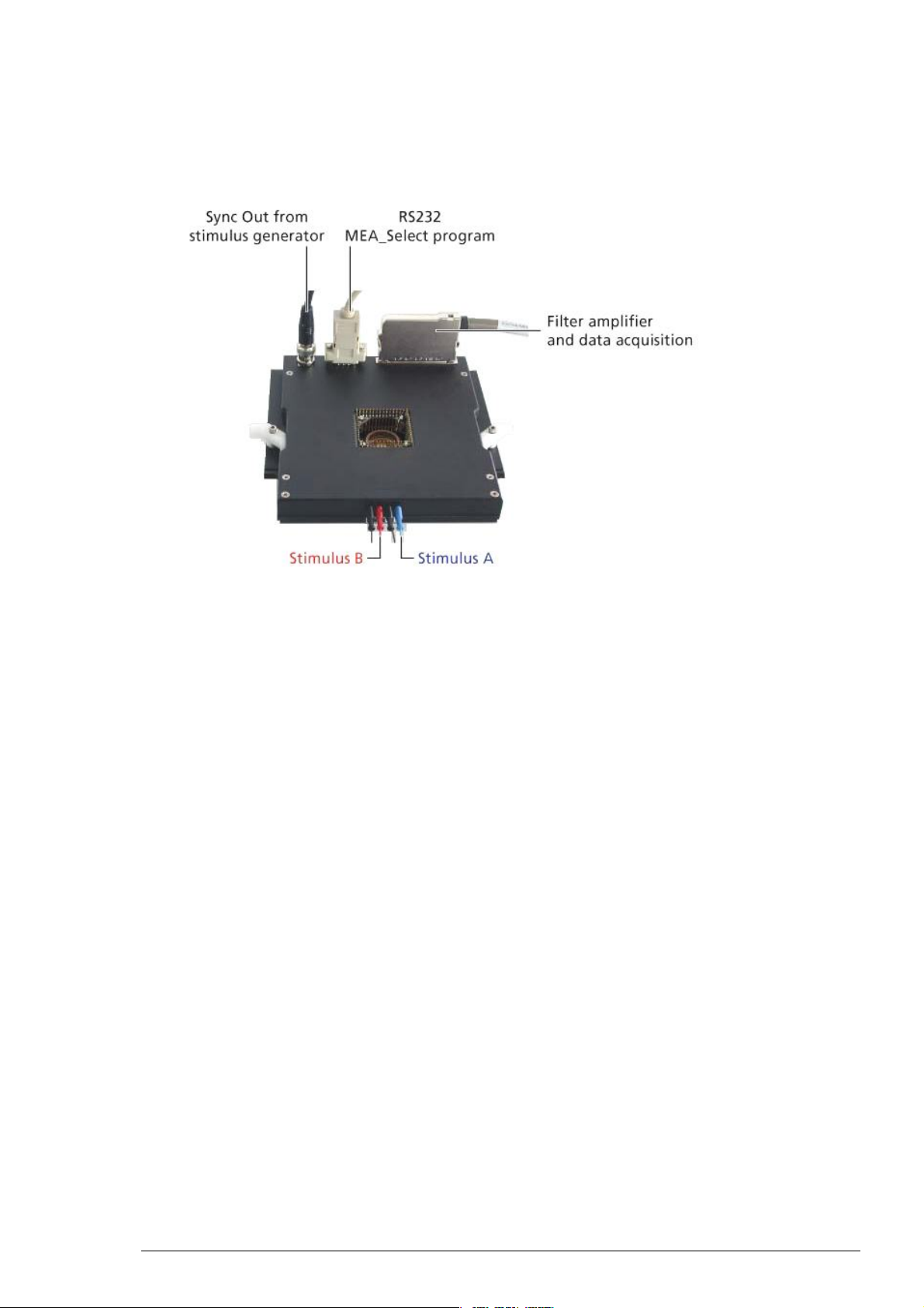
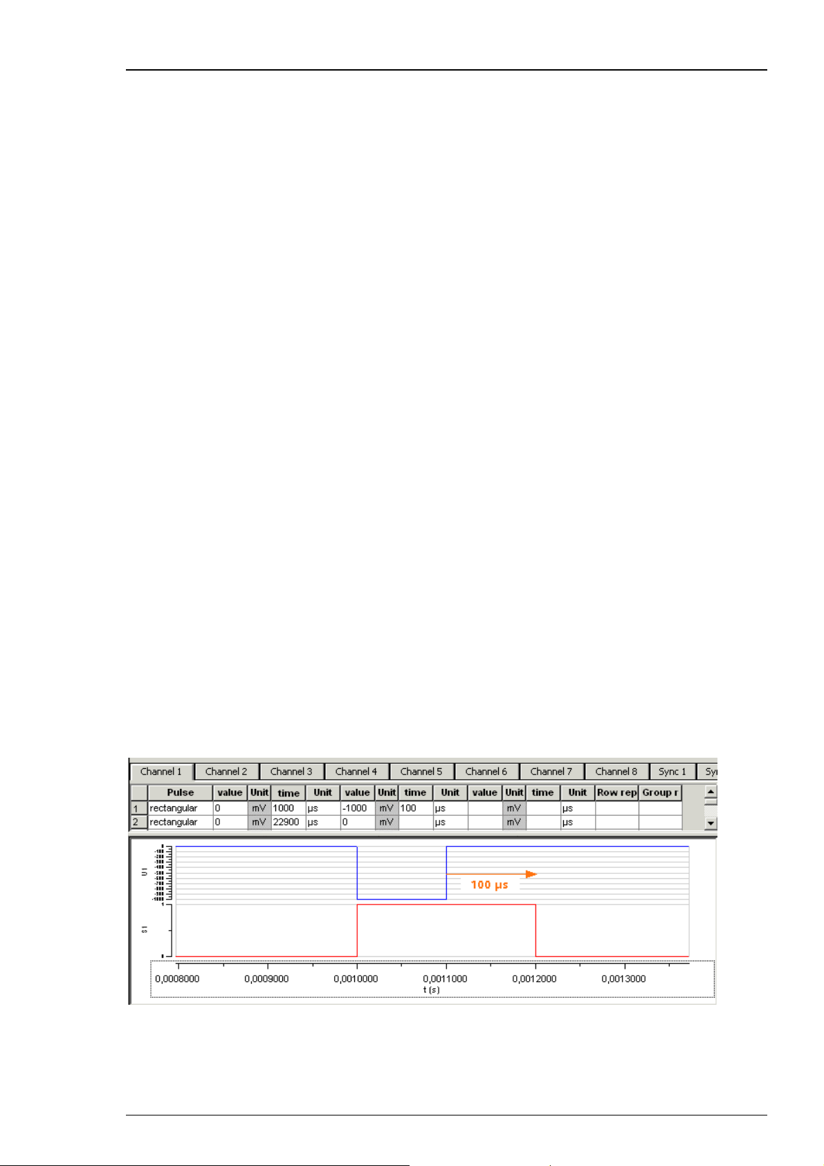
3.3 MEA_Select Program
MEA Amplifier with blanking circuit (MEA1060-BC)
First Use of the MEA Amplifier
When starting the software program MEA_Select for controlling the blanking circuit of the
MEA amplifier the main window appears. You see the electrode button array on the left side.
Select the MEA layout from the drop down menu and the electrode button array will be adapted.
Click any or “All" button to select any or all electrodes for recording, stimulation or grounding.
Electrode button array adapted for 4QMEA1000 layout and HexaMEA layout.
The Stimulation window provides four options: Not Stim. = Recording (the button in MEA
layout is grey and labeled with the number of the electrode. Ground (the button in MEA layout
is grey without number of electrode. Stim. A = Stimulation A (the button in MEA layout is blue
and labeled with the number of the electrode). Stim. B = Stimulation B (the button in MEA layout
is red and labeled with the number of the electrode). The software allows to select any electrode
on a MEA for recording, grounding, and stimulation. You can apply two different stimulus
protocols A and B.
7
Page 12

MEA Amplifier with Blanking Circuit for Inverse Microscopes
A blanking signal (TTL pulse) transiently switch off the input stage of the amplifier during the
stimulus, thus avoiding the stimulus artifacts on non-stimulating electrodes. Amplifier saturation
is effectively prevented and the recovery time is greatly reduced. It is also possible to record from
stimulation electrodes shortly after stimulation.
With the MEA_Select program, it is easy to change the electrode selection during the experiment,
for example, to use stimulation electrodes for recording and vice versa. You can also ground
unwanted or bad electrodes by mouse click. Do not forget to send modified settings to the
MEA amplifier with Download command.
Without blanking technology, recovery time depends on the filter amplifier type. It is roughly
the time constant of the high pass filter multiplied by ten. During this time, the data output is
distorted. With the blanking circuit, the voltage outputs of the preamplifier are held constant
during the time when the blanking input is active. Thus, the following filter amplifier does not
get saturated by the stimulus artifact. When the blanking signal has stopped, the channel output
follows the input signal again.
By pressing the button Download you send the setting information to the MEA amplifier.
Port shows the connection to the serial port RS232 to which the MEA amplifier is connected.
With the option Test Conn. = test connection you are able to check whether you connected
the MEA amplifier to the fitting serial port. If not there is an error message "Connection not Ok."
and you have to change the port and check the cable. If the connection is perfect the message
"Connection Ok” and the version of the firmware of the MEA_Select program are displayed.
The box Blanking must be enabled in most cases, but you can disable the blanking for testing
your amplifier, for example.
The button Change MEA sets all electrodes to ground and is used for manipulations on the
MEA amplifier. When replacing a MEA chip, the stabilizing time can be greatly reduced by
connecting all electrodes to ground during the opening of the amplifier and change of the MEA.
The connection to ground results in lower electrode offsets. Therefore, you should always use
the "Change MEA" command when replacing a MEA.
Important: Click Change MEA in the MEA_Select program before you remove the shielding or
open the amplifier. Deactivate the Change MEA mode only after having completely set up the
amplifier, including grounding the bath and shielding the amplifier. Otherwise, it can take very
long (several seconds to minutes) until the amplifier has recovered and is ready for operation.
On the right side of the main window the Configuration box gives you the possibility to reuse
electrode configurations which are saved before. The configuration file has the extension ".scl".
This feature is important for the reproducibility of experiments. You can also save the list of
blanking patterns in List Mode together with a configuration file or just the list.
You can use the Wait for optimizing the electrode's behavior. The Wait parameter is the delay
between switching the electrodes from stimulation back to recording, that is, the stimulating
electrodes are disconnected from the stimulus input at the end of the trigger signal, and all
electrodes are connected to the amplifier input at the end of the Wait period. The Wait helps
avoiding cross-talk between stimulating and non-stimulating electrodes as well as preventing
switch artifacts.
The length of the Wait depends on several factors (electrode performance, stimulus amplitude,
for example) and has to be optimized empirically for each experimental setup. To test this,
enter increasing Wait values and monitor the performance of the stimulus artifact suppression.
Generally, the lower the amplitude of your stimulus is, the shorter can be the blanking signal.
For strong stimuli, a Wait of up to 400 μs can be necessary.
A factory-set Wait of 40 μs is added to all user defined Wait values. For example, a user defined
Wait of 0 results in a total delay of 40 μs.
8
Page 13
First Use of the MEA Amplifier
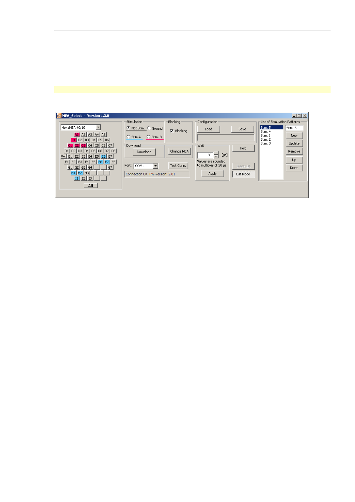
The command List Mode opens an additional window: List of Stimulation Patterns. In List
Mode you can download a list of up to 50 user defined stimulation patterns. The quantity of
50 patterns is hardware controlled. A stimulation pattern can contain single or multiple electrodes
and must get an user defined name. Click "New", and it appears in the small upper window pane.
Change "New" into your specific name for the actual pattern, click "Update" to confirm
the name and add the pattern to the list. By clicking the button Trace List, the stimulation
patterns in this list are applied one after the other as stimulation signals.
Note: A Firmware update is necessary to use this feature.
Please read chapter "Stimulation" for more information.
It is very convenient to use a stimulus generator and MC_Stimulus to set up both your stimuli
and the blanking signal. You can then use the digital Sync Out output channel for controlling
the blanking of the MEA preamplifier and triggering the recording with the MC_Card or an
USB based data acquisition device.
9
Page 14

MEA Amplifier with Blanking Circuit for Inverse Microscopes
3.4 Setting Up and Connecting the MEA Amplifier
Warning: Spilled liquid can damage or even completely destroy the electronics of the MEA
amplifier. Please be extremely careful when setting up your perfusion system and when starting
the perfusion. Take care that the flow rates of the inlet and outlet flow match so that flooding
of the amplifier is efficiently prevented.
Note: The housing of the MEA amplifiers was optimized for Zeiss Axiovert microscopes. MEA
Amplifiers are compatible to most standard microscopes if the following prerequisites are met.
This MEA amplifier type has been developed for standard inverse microscopes with a rectangular
microscope table. The focal plane of the microscope has to be in a distance of 3.5 mm to the
microscope table.
Note: If you use a complete MEA-System, the MEA amplifier will usually be powered by the
isolated power supply (IPS10W) that is integrated into the data acquisition computer. The power
is distributed along the MCS 68-pin MCS high grade cable. If you use your MEA amplifiers
together with a MEA Switch, or if you use a custom data acquisition system without IPS10W,
you will need an external power supply for operating the amplifier(s). Please ask your local
retailer for more information on setup options.
Note: If you use an USB-ME-System you need an external power supply, for example a PS40W,
for operating the amplifier(s). Please ask your local retailer for more information on setup
options.
1. Connect the MEA preamplifier with blanking circuit to the filter amplifier's input with a 68-pin
MCS standard cable.
Using the MC_Card for data acquisition: Connect the filter amplifier's output to the MC_Card
input labeled MC_Card Ch. 01–64 with a 68-pin MCS standard cable. If you have a MEA120-System,
connect the second MEA amplifier with a 68-pin MCS standard cable to the input for channels
65 to 128 labeled MC_CX64 Ch. 65–128. If you are using a MEA Switch, connect the amplifiers
to the MEA Switch inputs, and the MEA Switch outputs to the MC_Card.
Using an USB-ME data acquisition device: Connect the filter amplifier's output to the USB-ME
input via 68-pin MCS standard cable. If you are using a MEA Switch, connect the amplifiers to
the MEA Switch inputs, and the MEA Switch outputs to the USB-ME device.
1. Place the MEA amplifier onto the microscope table.
2. Connect the internal heating element to a Temperature Controller's output channel (D-Sub9
socket) with the black cable. (The Temperature Controller is not part of the standard scope
of delivery, but is included in the MEA-System or USB-ME-System, and can also be ordered
separately.) Do not connect the black heating element cable to the data acquisition computer.
3. Connect the serial port of the preamplifier to a free RS232 serial port of the computer, from
which you like to control the MEA amplifier (usually the data acquisition computer) with the
provided RS232 cable. Note that you need a separate Com port for each amplifier in use.
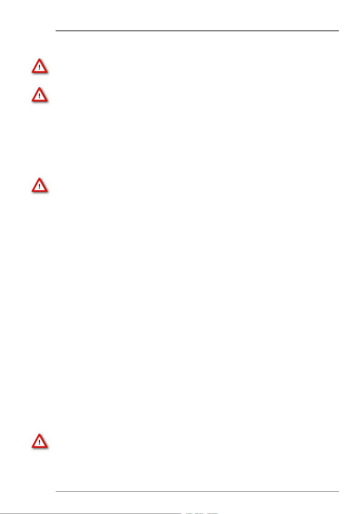
4. Connect up to two analog outputs of the stimulus generator to the two stimulus inputs of the
preamplifier. Connect the corresponding ground to the ground inputs. Please see the illustrations
below for details.
5. Connect a digital Sync Out output of the stimulus generator to the Trigger In input of the
preamplifier with a standard BNC cable. If you use a complete MEA-System, connect the same
Sync Out output to the first digital input bit of the MC_Card. Split the Sync Out output by using
a T-connector to connect the devices in serial, but not parallel! (Connect the T-connector to
the MEA amplifier or to the MC_Card output, but not to the STG output).
6. You should use a Faraday cage or appropriate materials, for example aluminum foil, for shielding
the amplifier. The shielding should be connected to the amplifier's ground, for example, to the
screws of the cover.
10
Page 15
First Use of the MEA Amplifier
Please see also the separate handout "MEA Microelectrode Systems" for setup suggestions with
detailed illustrations.
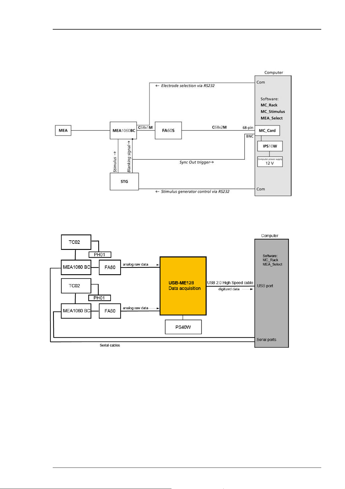
The following illustration shows a suggested setup for a standard MEA60-System with stimulus
generator and blanking circuit.
The following illustration shows a suggested setup for an USB-ME128-System with
a MEA1060 amplifier with blanking circuit.
11
Page 16
MEA Amplifier with Blanking Circuit for Inverse Microscopes
Connecting the amplifier to the stimulus generator
The following illustration shows the recommended setup for connecting a stimulus generator
to the MEA amplifier with blanking circuit. The amplifier is electrically connected to the stimulus
generator only during the short time of the blanking pulse. Therefore, a shielded cable that is
usually used for preventing the pick up of noise is not necessary. The first illustration shows a
typical monopolar stimulation setup. One output channel (usually +U) of the stimulus generator
is connected to either stimulus input A or B of the MEA amplifier. If you use two separate
stimulation patterns, connect channel 1 of the stimulus generator to stimulus input A, and
channel 2 to stimulus input B, and the corresponding ground for each channel to the ground
inputs (labeled G) of the MEA amplifier.
The next illustration shows a standard setup for dipolar stimulation. In this case, you connect
the +U outputs to either stimulus input (A or B) of the MEA amplifier. The U output of the same
channel is connected to the other input. The ground output of the same channel is connected to
either ground input (labeled G) of the amplifier. It does not matter, which ground input you use,
because both G inputs are internally connected. Usually, you will then select two neighboring
electrodes on the MEA for the dipolar stimulation, for example, electrode 33 for stimulus A and
electrode 34 for stimulus B.
For more information on the stimulus generator output signals, please see the Stimulus Generator
manual.
12
Page 17

4 First Tests and Tutorial
4.1 First Functional Tests
Each MEA amplifier has been thoroughly tested at the factory site before delivery. However,
you may want to perform some tests yourself before you begin your experiment to exclude
any damage that might have occurred during transportation, or to fulfill your own guidelines,
for instance.
Some of the tests will also help you to get to know the basic functions of the hard- and software,
like a short tutorial. It will take only a few minutes time and can save time and trouble in the long
run. Multi Channel Systems MCS GmbH recommends running these tests after the setup of your
system before you start your real experiments.
4.2 General Performance / Noise Level
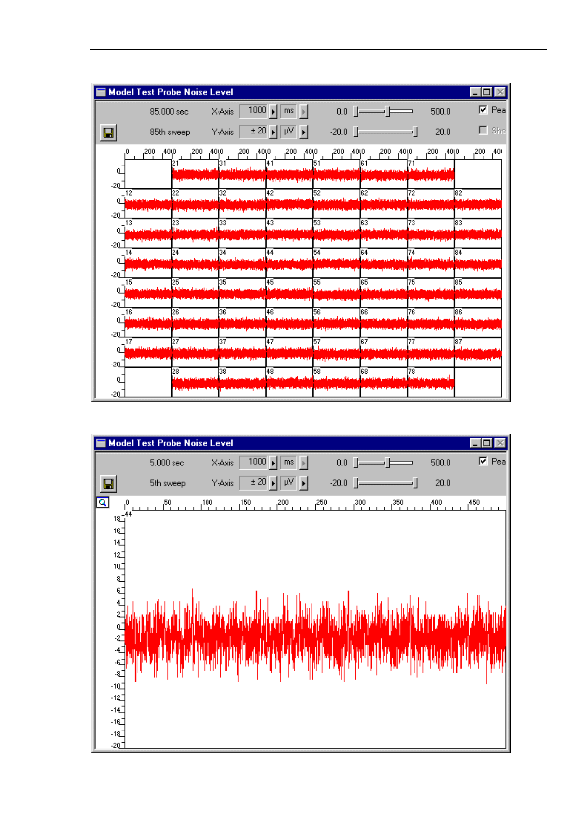
Please use the provided test model probe to test the amplifier immediately after installation.
The test model probe is already mounted on the amplifier. It simulates a MEA with a resistor
of 220 k and a 1 nF capacitor between bath and electrode. Use MC_Rack or your custom data
acquisition program to record from the test model probe and to check the amplifier.
Setting up MC_Rack
Please refer to the MC_Rack manual for more information.
1. Start MC_Rack.
2. Open the file MEA_Display.rck on the installation volume. This basic rack contains the virtual
MC_Card instrument with appropriate gain settings and a continuous raw data display.
- OR -
Set up the rack on your own:
1. Click Data Source Setup on the Edit menu. Select MC_Card or USB-MEA in Data Source
drop down menu. Select a 2-dimensional (MEA) layout or Configuration in Source Layout.
Close the dialog with OK.
2. Add the Data Source to your virtual rack.
3. Click the Hardware tab and enter the appropriate amplifier gain (standard: 1100).
4. On the Edit menu, click Add Data Display to add a raw data display to your virtual rack.
Starting the recording
1. On the Measurement menu, click Start to start the recording. You see the raw data streams
of all 60 channels in the typical MEA layout.
2. You may have to adjust the position and span of the axes until you can clearly see the noise
level.
During the first minute, you will see the baseline on all channels, because the filter amplifier
is still saturated. All electrodes have a different DC offset at the beginning of an experiment.
The internal baseline restore routine restores the offset to the ground level, that is, to zero.
During this time, you will not see any "true" signals or noise. See also the chapter "Operating
the MEA Amplifier", "Signal Amplification and Filters".
After about one minute, the baseline restorer has corrected the DC offset, and you see true
signals. You should see the baseline with a maximum noise level of +/- 8 μV.
13
Page 18
MEA Amplifier with Blanking Circuit for Inverse Microscopes
The following screen shot shows a recording from a typical MEA amplifier with a test model probe
and a sampling rate of 25 kHz.
Double-click a channel in the display to have a closer look.
14
Page 19
First Tests and Tutorial
4.3 Computer Connection
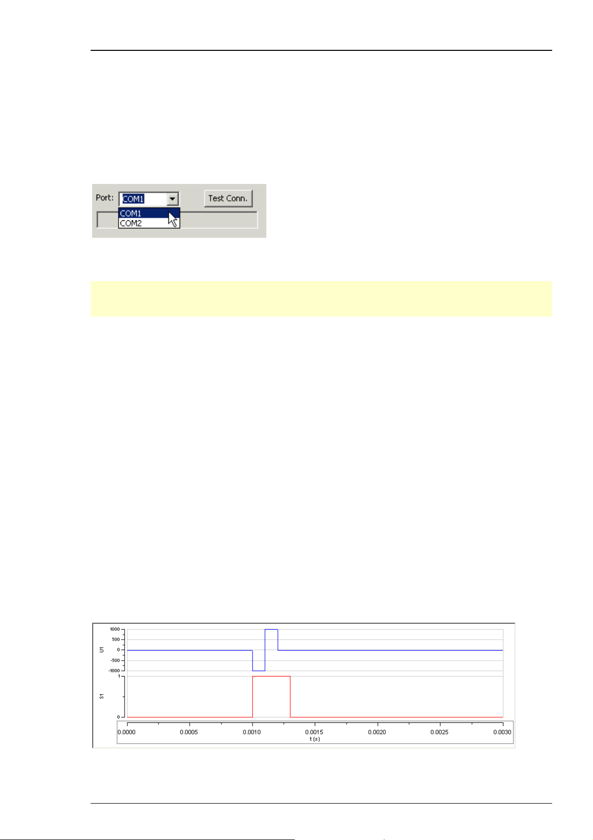
Testing the computer connection
The MEA_Select program automatically detects and lists all serial ports of your computer.
1. Start MEA_Select.
Select the serial port to which you have connected the MEA preamplifier (COM1, COM2,
and so on) from the drop down list.
1. Click Test Connection. A valid computer connection should be confirmed by OK. If not,
please check all cables and connections.
Note: You can control multiple MEA amplifiers from the same computer by starting several
instances of the MEA_Select program. Connect the amplifiers to different serial ports and
select the appropriate serial port for each amplifier in the MEA_Select program.
4.4 Stimulation and Recording
In this chapter, we provide a step by step instruction for first tests that we think useful for
learning more about the features and behavior of the amplifier. It is assumed that you will use
MCS components (MEA-System and stimulus generator) for the complete setup. Please make sure
that you have set up the system as described in the chapter "Setting Up and Connecting the MEA
Amplifier" (or likewise, if you use other components). You can use the provided test model
probe for your first experiment.
First, you have to set up your stimulus generator and MC_Rack. Then you can start MEA_Select
to operate the MEA amplifier. Of course, you can also change your MC_Stimulus or MC_Rack
settings during amplifier operation.
Setting up the Stimulus Generator of 4000 series
1. Start the stimulation software MC_Stimulus II.
2. Open the demo stimulus file on the installation volume. You can choose between a monophasic
and biphasic stimulus (biphasic stimuli with the negative phase first are recommended). The
voltage demo stimulus is a biphasic or monophasic pulse with a duration of 100 μs for each phase
and an amplitude of 1 V / +1 V. The pulse is repeated continuously each 24 ms (with the Repeat
feature of MC_Stimulus). The Sync Out trigger pulse for triggering the MEA amplifier and the
MC_Card is 100 μs longer than the stimulus pulse.
3. On the STG menu, click Download (all) to download the file onto the stimulus generator.
15
Page 20
MEA Amplifier with Blanking Circuit for Inverse Microscopes
4.4.1 Operating multiple MEA Amplifiers with one STG
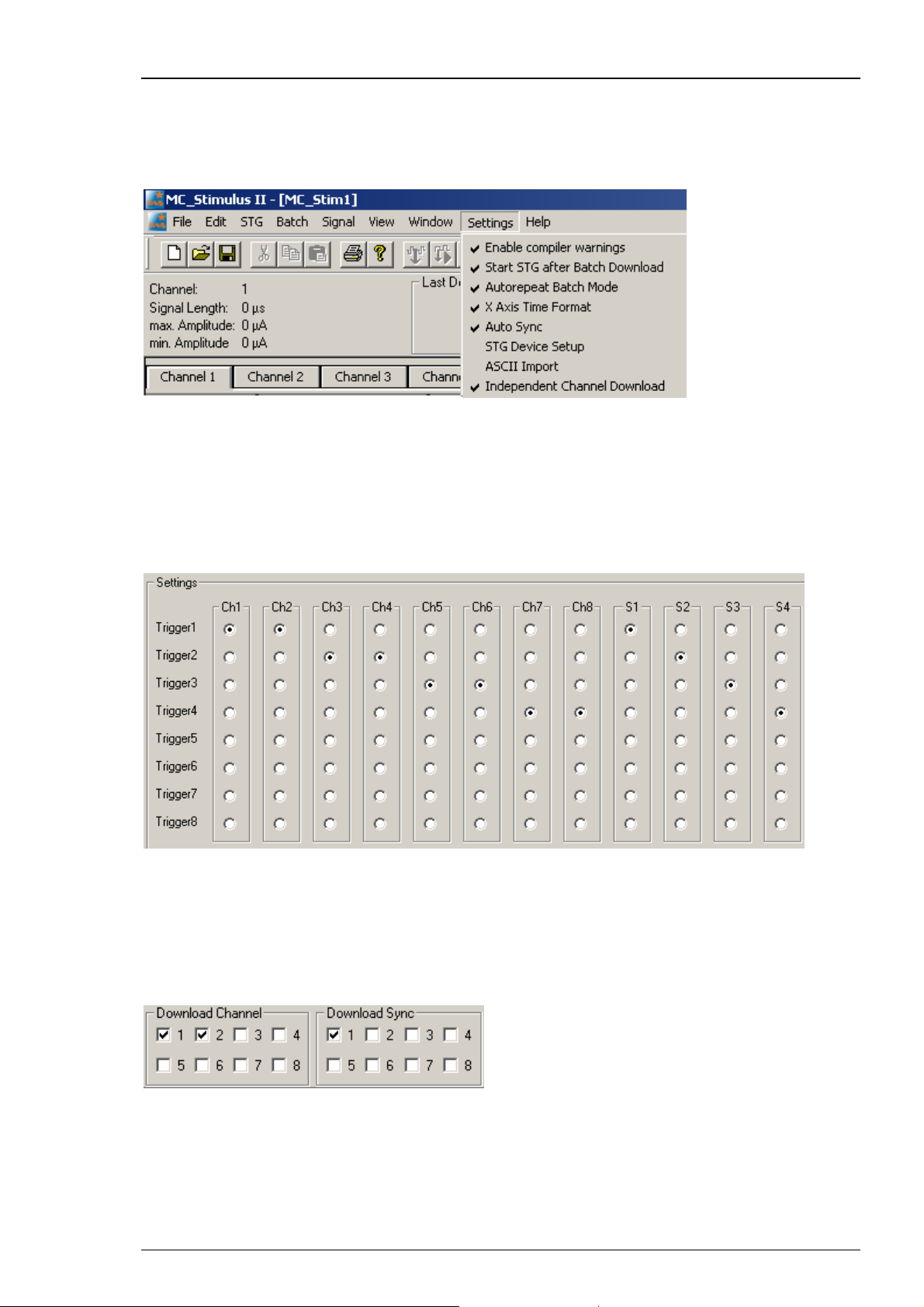
It is possible to operate more than one MEA amplifier independently with a single stimulus
generator of the 4000 series. To do this, activate the Independent Channel Download feature
in the Settings menu of MC_Stimulus II.
This feature will allow to download new stimulation paradigms to individual channels without
interrupting the ongoing stimulation on other channels. See chapter “Downloading Stimulus
Files” for more information.
It is mandatory that all stimulation and Sync Out channels that are associated with one amplifier
are assigned to the same trigger in the Trigger Settings menu. For example, if four MEA1060-
BC amplifiers are connected to one STG4008, usually two stimulation channels and one Sync Out
are associated to each amplifier. In that case, the trigger settings should be as shown:
Amplifier A is connected to stimulation channels 1 and 2 and Sync Out 1, Amplifier B
is connected to stimulation channels 3 and 4 and Sync Out 2, and so on. All channels
connected to one amplifier are assigned to the same trigger.
To download a stimulation paradigm to individual channels assigned to one amplifier only, select
all channels connected to this amplifier in the “Download Channel” check box (1 and 2 in this
example) and Sync Out 1 in “Download Sync” check box, whether you changed them all or not!
Only these channels will be downloaded, ongoing stimulation on other channels will not be
interrupted.
16
Page 21

First Tests and Tutorial
To start and stop only the channels associated with one amplifier, use the Start / Stop buttons
for individual triggers. Each button controls one trigger and hence all assigned channels. The
orange LED indicates ongoing stimulation. In our example, the configuration shown below
would mean that amplifiers A, B and D are receiving a stimulation signal, while stimulation for
amplifier C is stopped.
Triggers 5 to 8 have no function in this example. You could download a new paradigm for
amplifier D by downloading channels 5 and 6 and Sync Out 3, and then start it with the start
button of Trigger 3. This would not interfere with the ongoing stimulation to the other three
amplifiers, but only if the Independent Channel Download function is activated. If the STG
is in default download mode, any download will stop all ongoing stimulation and empty the
memory of the STG. See chapter “Downloading Stimulus Files” for more information.
Data acquisition with MC_Rack
1. Start MC_Rack.
2. Open the demo rack file MEA1060BC_demo.rck on the installation volume. It is a simple rack
with only a Trigger Detector, one continuous and one triggered Data Display. You will need
a trigger for stimulation and blanking, and for triggering the triggered display.
3. Bring the continuous display to front.
4. Start the recording by clicking Start.
Operating the MEA amplifier with blanking circuit
Start MEA_Select.
On the left, you see the MEA layout button array. Here, you can select any electrodes for
stimulation or connect them to ground. The default state of all electrodes is selected for
Recording = Not Stim.. This is indicated by the neutral grey background of the electrode buttons.
Accordingly, you will see the standard noise level on all channels in the continuous display in the
MC_Rack program. The triggered display is still empty, because you have not started triggering
the stimulation and the MC_Card yet.
Grounding electrodes
You can connect any electrode to ground. Usually, you will ground defective electrodes.
Now, we are trying out this feature even if it makes no sense with the MEA test model probe.
17
Page 22
MEA Amplifier with Blanking Circuit for Inverse Microscopes
1. Under Stimulation, select Ground.
2. Click any electrodes that you like to ground, for example electrodes 36, 46, and 56. Grounded
electrodes show no electrode number, only a blank button. By clicking on one of the grounded
electrodes again you can toggle back to recording mode. If you click, for example in Stimulation
mode B onto a grounded electrode, you overwrite the grounded mode with Stim. B mode. That
means, the color will turn to red and the number of the electrode appears again. If you click for
the third time, the selected electrode toggles back to recording (= default) mode.
3. Click Download to download this information on the MEA amplifier.
4. Switch to the MC_Rack display.
You can see that the noise level of the grounded electrodes is reduced. The effect is quite
small because the model test probe has no defective electrodes and shows a fine low noise
level on all "electrodes".
18
Page 23
First Tests and Tutorial
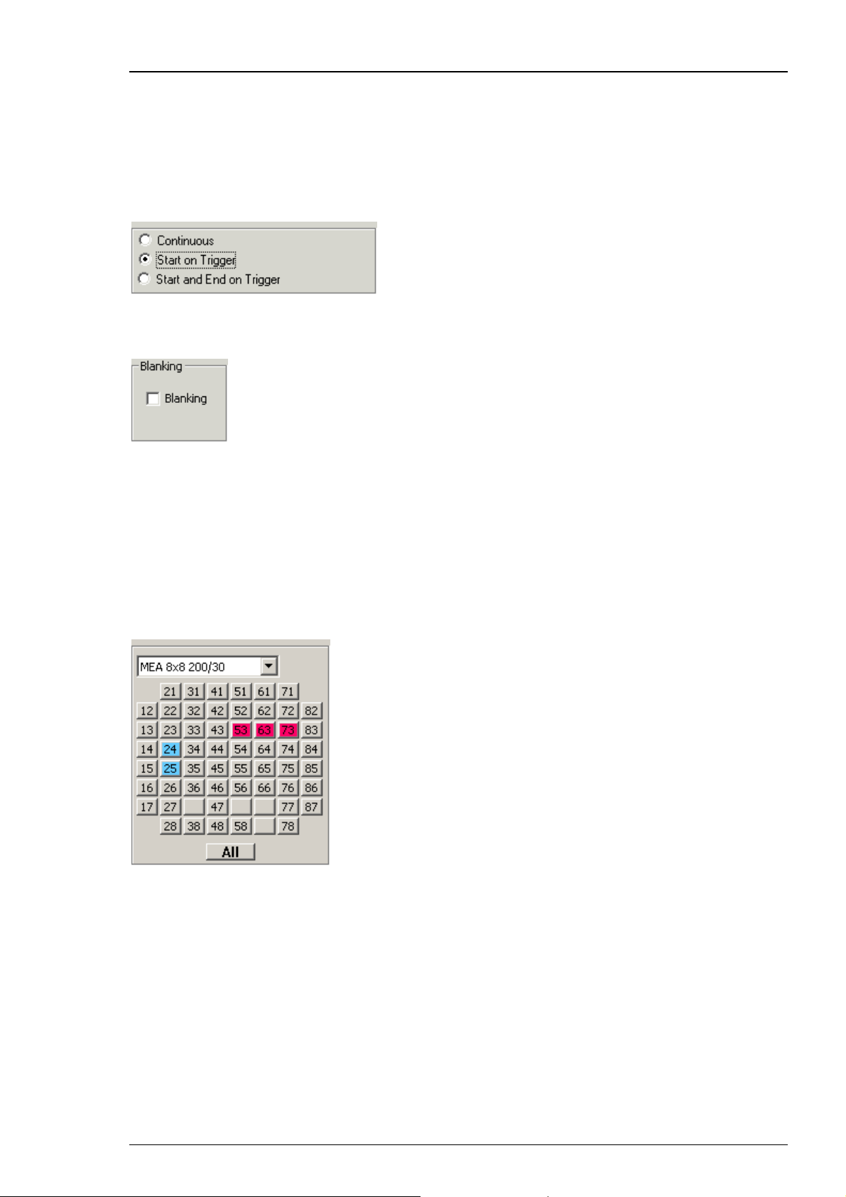
Stimulation without blanking
Usually, you will always use the blanking when you stimulate. But it is possible to switch off
the blanking for testing your setup.
1. In MC_Rack, bring the triggered display to the front. Make sure you have connected the digital
Sync Out output of the stimulus generator to the digital channel 1 (bit 0) of the MC_Card.
Otherwise, you have to select the appropriate bit in the Trigger Detector.
2. In MEA_Select, under Blanking, deselect Blanking.
3. Under Stimulation, select the appropriate stimulus input (Stim A or Stim B).
4. Click any electrode that you like to use for stimulation, for example 53. The stimulation electrodes
are marked by a color, that is, blue for stimulus A and red for stimulus B. By clicking on one of the
selected electrodes again you can toggle back to recording mode. If you click, for example in
Stimulation mode B onto a blue (Stim. A) or grounded electrode, you overwrite the mode with
Stim. B mode. That means, the color will turn to red and the number of the grounded electrode
appears again. If you click for the third time, the selected electrode toggles back to recording
(= default) mode.
5. Click Download to download this information on the MEA amplifier.
6. Start the stimulus generator.
19
Page 24
MEA Amplifier with Blanking Circuit for Inverse Microscopes
The stimuli are sent to the selected stimulation electrodes. You see stimulus artifacts on all
channels. The display operates now in a triggered mode, so that the stimuli appear aligned
to the trigger event.
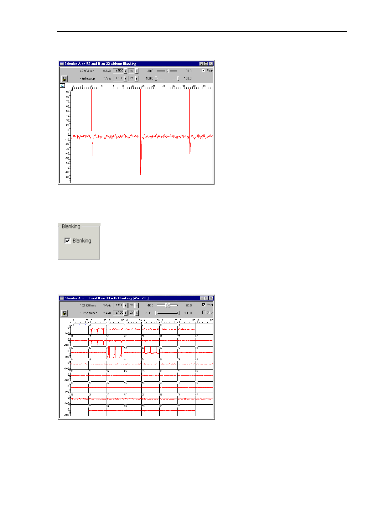
Stimulation with blanking
1. Select the Blanking in the MEA_Select program.
2. The Sync Out signal of the stimulus generator triggers not only the stimulation,
but the blanking as well.
20
Page 25
First Tests and Tutorial
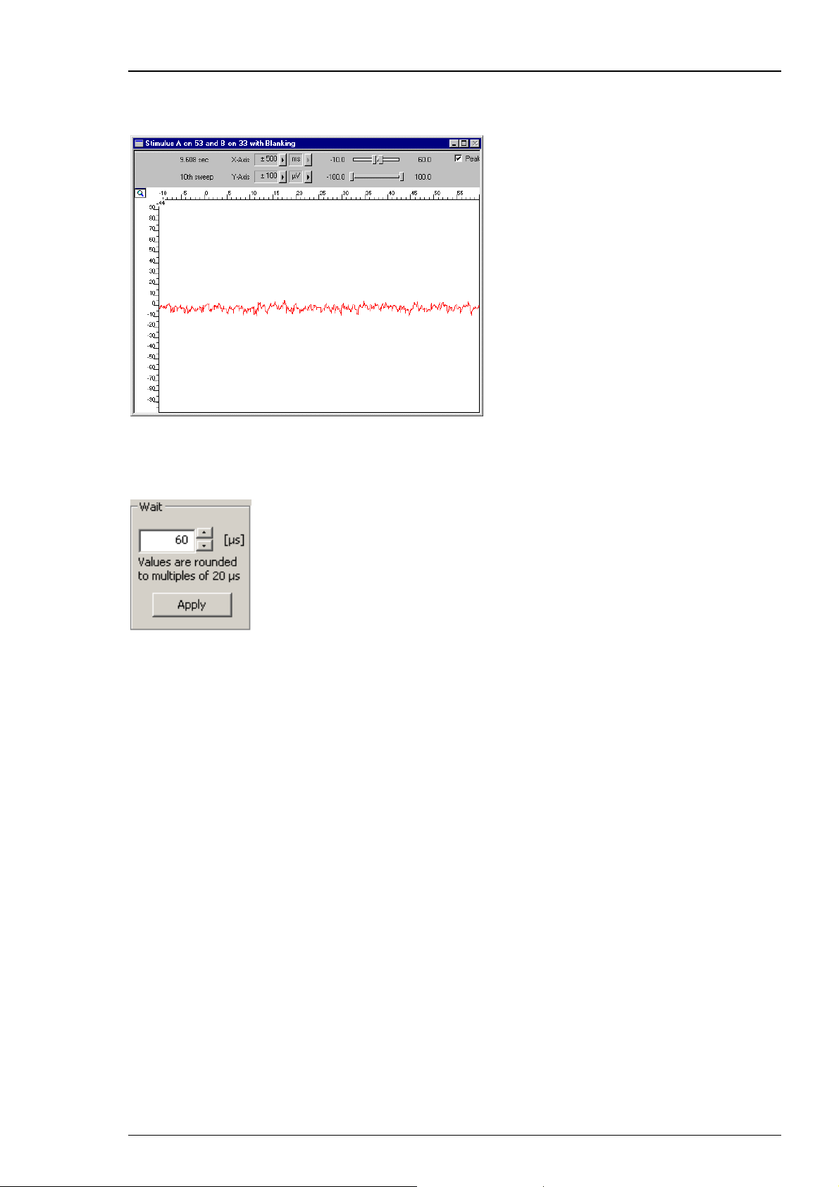
You see that there are no stimulus artifacts visible on almost all non-stimulating electrodes,
with some residual artifacts on the neighbor electrodes of the stimulating electrode 33.
In this example, we have used a Wait of 200 μs.
Wait settings
You can use the Wait for optimizing the electrode's behavior. The Wait parameter is the delay
between switching the electrodes from stimulation back to recording, that is, the stimulating
electrodes are disconnected from the stimulus input at the end of the trigger signal, and all
electrodes are connected to the amplifier input at the end of the Wait period.
The Wait helps avoiding cross-talk between stimulating and non-stimulating electrodes as well as
preventing switch artifacts.
The length of the Wait depends on several factors (electrode performance, stimulus amplitude,
for example) and has to be optimized empirically for each experimental setup.
Enter increasing Wait values and monitor the performance of the stimulus artifact suppression.
21
Page 26

Page 27

5 Operating the MEA Amplifier
5.1 Signal Amplification and Filters
The MEA amplifier with blanking circuit is a 60-channel preamplifier with a broad bandwidth.
Filter specifications and gain are defined by the following filter amplifier.
Different filter settings are used for different applications to enhance the signal-to-noise ratio.
The pass band of the filter amplifier should be chosen according to the signal type. It is generally
useful to set the upper limit of the amplifier near the highest expected signal frequency, but also
at a safe distance to make sure that the full gain is used for signal amplification.
For slow signals like field potentials, a bandwidth of 1 to 300 Hz is appropriate. If you like to
record fast signals like spikes, a passband of 300 Hz to 3 kHz is suitable. Cardiac signals have
fast and slow components; therefore, you usually need a wider bandwidth of 1 Hz to 3 kHz.
Multi Channel Systems provides custom amplifiers with a bandwidth of your choice, from 0.1 Hz
to 10 kHz. Please note that it is often useful to acquire the data with a broadband amplifier and
use the digital filter of the free MC_Rack program to change the pass band and filter the raw
data. This way, you are much more flexible in designing your experiments. As a further
advantage, you can see the original (not filtered) data as well. This is especially important because
all filters are known to distort signals. On the other hand, you may need a higher sampling rate to
avoid aliasing, and you will have a lower signal to noise ratio.
The standard gain of a MEA amplifier is 1200 (1100 in case of a MEA amplifier with blanking
circuit), which is fine for most applications, but MCS can also provide amplifiers with a gain
of your choice (from 100 to 5000) as well. For large signals (for example, from whole-heart
preparations), you need a lower gain to prevent a saturation of the amplifier. Please note that
the gain is a fixed hardware property; and that you cannot change the gain of the amplifier
by software controls. For more information on the technical specifications of your amplifier,
please see the separate data sheet that is delivered with each amplifier.
Please note that the ratio of the output signal to the input signal, that is, the gain, is not
a fixed parameter for the complete bandwidth. The gain that was specified for the amplifier,
for example, 1200, is not fully reached at the borders of the amplifier's pass band. The general
rule is, that at the lower and upper limit of the frequency band, the gain is
approximately 70 %, of the full gain. Therefore, you should use a bandwidth that is at a safe
distance of the signals of interest. Outside the pass band, the gain decreases with the frequency
and finally approaches zero.
The first illustration shows the broad frequency band of the MEA1060-BC amplifier alone (without
Filter Amplifier); the following illustration shows a typical frequency band of the MEA amplifier
with standard gain and bandwidth (in blue). Output signal amplitudes were divided by the input
signal amplitude and the resulting gain was plotted versus the input signal frequency on a
logarithmic scale. A straight line at approximately 70 % of the specified gain intersects the plotted
curve at the lower and upper limit of the pass band. The low pass filter property of the combined
MEA1060 amplifier and MC_Card (in black) is only slightly different.
, that is
23
Page 28

MEA Amplifier with Blanking Circuit for Inverse Microscopes
For information on the gain and filters of the MC_Card data acquisition system,
please see the ME- / MEA-System manual. For more information on gain and filters
in general, please refer to standard literature or contact your local retailer.
If you use a MEA-System, the isolated power supply IPS10W that is integrated in the data
acquisition computer supplies the power for operating the MEA amplifier. The power is
distributed along the MCS high grade cable. Please consider that the amplifier can only
operate properly if the supply voltage and current specifications are fulfilled, especially
if you use a custom power supply. See also the Technical Specifications and the
Troubleshooting section.
24
Page 29

Operating the MEA Amplifier
DC offset correction
The internal baseline restore routine of the preamplifier restores the offset to the ground level,
that is, to zero. This has to be a slow process. If the routine corrected too fast, slow signals would
be eliminated as well.
All electrodes on an array have different DC offsets at the beginning of an experiment. The
DC offsets are amplified by the preamplifier, and the amplified output signal of the preamplifier
is likely to exceed the input range of the following filter amplifier. In order to eliminate this
DC offset, a so-called baseline restorer is integrated in the preamplifier. For signals in the usual
measurement range, the baseline restore routine acts like a high pass filter with a very low
cut-off frequency of roughly 0.01 Hz, but unnaturally high signals like stimulus artifacts are
limited to a negligible value.
Due to the low cut-off frequency, the baseline restorer takes some time to stabilize after
switching on the amplifier or after replacing the MEA. One to two minutes are quite normal.
During this time, the filter amplifier input will be overloaded and you will see only a straight
line with very low noise. This is considered a normal behavior and should not trouble you.
Please wait until the baseline restore routine has been completed.
When replacing a MEA, the stabilizing time can be greatly reduced by connecting all electrodes
to ground during the opening of the amplifier and change of the MEA. The connection to ground
results in lower electrode offsets. Therefore, you should always use the Change MEA command
when replacing a MEA. See also the chapters First Tests and Tutorial, General Performance / Noise
Level and Operating the MEA Amplifier, Mounting the MEA Probe.
5.2 Temperature Control
The biological sample is cultured directly on the MEA. You can record without needing an
incubator, because a heating element is integrated into the amplifier and the perfusion cannula
and are both controlled by a Temperature Controller (Temperature Controller and perfusion
cannula with heating element and sensor are either included in the MEA-System or can be
ordered separately). You have several options regarding the culture chamber, such as a
semipermeable seal that guarantees stable environmental conditions.
For using the integrated heating element of the MEA amplifier, connect it with the black cable
to the Temperature Controller. The heating is active, but the cooling is passive. Therefore,
the minimum temperature is limited by the room temperature. Please refer to the Temperature
Controller manual for more information.
Important: Please make sure that you have selected the appropriate PID coefficients for the
amplifier type (for inverted or upright microscopes) in use.
25
Page 30

MEA Amplifier with Blanking Circuit for Inverse Microscopes
5.3 Mounting the MEA Probe and Grounding the Bath
Warning: Do not use too much force. Otherwise you could damage the delicate MEA
or contact pins of the amplifier. Put the lid of the amplifier only onto a dry and clean
area with the bottom side down. Otherwise, you can easily damage the contact pins.
Important: Click Change MEA in the MEA_Select program before you remove the shielding or
open the amplifier. Deactivate the Change MEA mode only after having completely set up the
amplifier, including grounding the bath and shielding the amplifier. Otherwise, it can take very
long (several seconds to minutes) until the amplifier has recovered and is ready for operation.
Mounting the MEA Probe
1. In the MEA_Select program, click Change MEA.
All electrode inputs are connected with the amplifier's ground. This helps avoiding
a large DC offset and reduces the baseline restoring time significantly. See also the
chapters "Operating the MEA Amplifier", and "Signal Amplification and Filters".
2. Place the MEA amplifier as shown on the photo. Open the lid of the MEA amplifier.
3. Place the MEA probe inside.
Important: MEA chips are not symmetrical! That is, why the writing (NMI) on the MEA chip should
be on the right side. Otherwise, the MEA layout will not match with the pin layout of the channel
map in MC_Rack. This is very important for MEAs with internal reference electrode, for example.
4. Replace the lid and close it carefully. Do not unpress the Change MEA button until
you have grounded the bath and replaced the shielding, that is, until the setup has
been completely finished.
Warning: Spilled liquid can damage or even completely destroy the electronics of the
MEA amplifier. Please be careful when setting up your perfusion system and when starting
the perfusion. Take care that the flow rates of the inlet and outlet flow match so that
flooding of the amplifier is efficiently prevented.
26
Page 31

Operating the MEA Amplifier
Grounding the bath
You can ground the bath with a plain silver wire or with an Ag/AgCl pellet. Only the Ag/AgCl
electrode provides a stable intrinsic potential. In practice, the plain silver wire will be ok for 90 %
of applications. If you do not achieve satisfying results with the plain silver wire, try an Ag/AgCl
electrode.
If you use MEAs with internal reference electrode, you can use the reference electrode for
grounding the bath. This has the advantage that you can keep the culture chamber closed
and sterile (for example, with MEA-MEM semipermeable membranes).
Important: If you use a MEA with internal reference electrode, you have to connect pin 15
to ground with the provided cable. Setting electrode 15 to ground in the MEA_Select program
is not sufficient for grounding the bath.
1. Attach the provided silver wire or pellet to the amplifier's ground and place it into the bath,
near the rim of the culture chamber. If you use a MEA with internal reference electrode,
connect the ground to the reference electrode socket (pin 15) with the provided connector.
Make sure that the orientation of the MEA inside the amplifier is appropriate.
2. Replace the shielding. Make sure the setup is complete.
3. Click Change MEA again to reconnect the electrodes to the amplifier's input stage.
4. Wait until the amplifier has recovered and you see the standard noise level on all channels
before starting your experiment. The recovery time depends on the electrodes used and usually
takes about one or two minutes.
27
Page 32

MEA Amplifier with Blanking Circuit for Inverse Microscopes
5.4 Grounding Defective Electrodes
You can ground defective electrodes with the MEA_Select program. In the following example,
electrodes No. 15, 16, 24, 25, 26, 35, and 47 show a very high noise level.
1. Under Stimulation, select Ground.
2. Click any electrodes that you like to ground.
Grounded electrodes show no electrode number, only a blank button.
3. Click Download to download this information on the MEA amplifier.
28
Page 33

Operating the MEA Amplifier
You can clearly see the difference between the high noise level and the zero line
of the grounded electrode.
29
Page 34

MEA Amplifier with Blanking Circuit for Inverse Microscopes
5.5 Stimulation
Recommended stimulus protocols for MEA electrodes
MCS recommends to use only biphasic voltage pulses with the negative phase first. The
duration of the pulse should be 100 μs for each phase and the amplitude between 100 mV
and 3000 mV. Make sure that the voltage level of the stimulating electrode is zero at the
end of the pulse. (See also Potter, S. M., Wagenaar, D. A. and DeMarse, T. B. (2005). Closing
the Loop: Stimulation Feedback Systems for Embodied MEA Cultures. Advances in Network
Electrophysiology Using Multi-Electrode Arrays. M. Taketani and M. Baudry, Springer;
Wagenaar, D. A., Madhavan, R., Pine, J. and Potter, S. M. (2005). "Controlling bursting
in cortical cultures with closed-loop multi-electrode stimulation." J Neurosci 25(3): 680-8.)
Stimulation with MEA electrodes
You can apply two different stimulus protocols to any selection of electrodes. Use the MEA_Select
program to select electrodes for recording and stimulation. The stimulation is triggered with a TTL
pulse, the so-called blanking signal. Please see "Blanking" for more information how to set up
and time the blanking signal.
You can also stimulate without blanking, for example, for testing your setup. Under Blanking,
deselect the Blanking option for disabling the blanking function.
Important: You can only stimulate during an active TTL pulse, which is used for triggering
the stimulation and the blanking (see illustration of switch positions below). You can switch off
the blanking for test purposes, but this is not considered a useful mode of operation, because
the amplifier will get saturated by the high stimulus input without blanking.
Important: The input voltage of the MEA1060-BC amplifier is limited to +/- 5 V. Exceeding
the voltage input range can result in unpredictable noise and artifacts. In rare cases, even damage
to the amplifier electronics might occur. For current driven stimulation, the voltage amplitude
depends on the electrode impedance. As the electrode impedance depends on several parameters,
for example, the electrode's degree of wear and its hydrophilicity, and therefore cannot be
predicted, it is generally recommended to use only voltage driven stimulation. Current driven
stimulation may work with larger (30 μm) TiN electrodes that have a low impedance, but this
cannot be guaranteed by the manufacturer.
For more information on the setup, please see the chapter “Setting Up and Connecting
the MEA Amplifier”.
30
Page 35

Operating the MEA Amplifier
Under Stimulation, select a stimulus input (Stim A or Stim B) and click any buttons on
the button array in the MEA layout. Click any electrode that you like to use for stimulation,
for example 23 or 73. The stimulation electrodes are marked by a color, that is, blue for stimulus A
and red for stimulus B. By clicking on one of the selected electrodes again you can toggle back to
recording mode. If you click, for example in Stimulation mode B onto a blue (Stim. A) or grounded
electrode, you overwrite the mode with Stim. B mode. That means, the color will turn to red and
the number of the grounded electrode appears again. If you click for the third time, the selected
electrode toggles back to recording (= default) mode.
1. Click Download to apply the settings. This single stimulation pattern will be repeated
as stimulation pulse until you download a different one.
If you like to download several (up to 50) stimulation patterns, click List Mode. Now you can
create a list of different stimulation patterns. In the small upper window pane the term "New"
will appear and you can change it into the specific name you will give the current stimulation
pattern, for example, Stimulation Pattern 1 = Stim. 1, Stim. 2, Stim. 3. With Update you can
confirm the name and the pattern will be added to the list of stimulation patterns in the left
window pane. Remove eliminates the pattern, which is highlighted in blue. With up or down
you can move the saved patterns in the list to arrange them in that sequence you like to apply
them. To duplicate a saved pattern you have to click the selected pattern, so that it is highlighted
in blue and confirm the same name with Update again. Click Download to send the list of
stimulation patterns to the MEA amplifier.
31
Page 36
MEA Amplifier with Blanking Circuit for Inverse Microscopes
If the List Mode is open, there is an additional button Trace List.
If the Trace List button is active all other functions are automatically disabled. The stimulation
patterns of the list, created in List Mode, are applied one after the other as stimulation pulse.
To control which pattern of the list is reached the name of the stimulus pattern will be
highlighted in blue. Reaching the end of the list, the program reruns the list of the stimulation
patterns, starting at the top of the list again. It is not recommended to change the settings of
stimulation patterns during experiment. Please stop recording data, change settings and send
the new information to the amplifier with Download. Then start recording again. It is possible
to save the list of stimulation patterns by clicking Save under Configuration together with
a previously loaded configuration file or you can save the list only. The file for just the list has
the same extension as the configuration file ".scl".
Note: A Firmware update is needed to use this feature.
During the blanking signal, the stimulus inputs are connected to the software-selected
stimulation electrodes, and all MEA electrodes are disconnected from the amplifier.
The last signal value on all electrode channels before the blanking pulse is applied will be
saved and then kept until the channels are reconnected to the amplifier.
32
Page 37
5.6 Stimulus Artifact Suppression (Blanking)
A TTL pulse (blanking signal) that has to be timed exactly with the stimulus pulse triggers
both the stimulation and the blanking. During the blanking signal, both stimulus inputs are
connected to the software-selected stimulating electrodes (A and B), and all MEA electrodes
are disconnected from the amplifier. The last signal value on all electrode channels before the
blanking pulse will be saved and then kept until the channels are reconnected to the amplifier.
This avoids that the amplifier gets saturated on all channels during stimulation (which is the case
with standard amplifiers). You can disable the blanking for test purposes.
The stimulus artifact suppression performance depends mainly on the electrical state of the
electrode (that is the residual net charge of the electrode). This depends on the stimulus type
(current or voltage driven, biphasic or monophasic), strength of the stimulus (amplitude,
duration, and frequency), on the electrode type and size, and other parameters and has to be
determined empirically. Complete artifact suppression may not always be possible, depending
on those parameters. Generally, the stimulus artifact suppression performance is much better
when using voltage driven stimulation than current driven stimulation. In the following, you will
find some general recommendations for an improved stimulus artifact performance, but please
understand that it is not possible for us to discuss all possible variations in this document.
Timing and duration of blanking signal
Operating the MEA Amplifier
For most applications, MCS considers a delay in the range of 100 μs suitable for discharging the
electrode and recommends a minimum blanking pulse that starts with the stimulus and stops
100 μs after the stimulus. The fact that the digital output of the stimulus generator from MCS
is about 20 μs faster than the analog output ensures that the blanking signal is delivered before
the stimulus. If you use a pulse generator from a supplier other than MCS, you may have to use
other trigger settings. It is very important that the blanking pulse is delivered slightly before the
stimulus.
For improving the blanking performance, you can try to extend the blanking pulse after the
end of the stimulus pulse. This gives the electrodes a longer time to discharge before they are
disconnected from the stimulus inputs. The charge carrier cannot flow back to the STG after the
end of the TTL pulse because the connection is interrupted. MCS recommends to try out 500 μs
and then decrease the time length stepwise for optimization if you observe problems with the
artifact suppression performance. The AutoSync feature of the STG 2000 or 4000 series makes
it easy to adapt the Sync Out output of your stimulus protocol.
The following example shows a blanking signal (programmed with MC_Stimulus) of 200 μs
length for a monophasic voltage pulse of 100 μs length.
33
Page 38

MEA Amplifier with Blanking Circuit for Inverse Microscopes
Wait settings
A delay (up to 5000 μs) between stopping stimulation (end of TTL pulse) and restarting the
recording can be programmed with the Wait property in the MEA_Select program in order to
optimize the blanking. The stimulation electrodes are disconnected from the stimulus input
at the end of the trigger signal, and all electrodes are connected to the amplifier input at the
end of the Wait period.
The Wait helps avoiding cross-talk between stimulating and non-stimulating electrodes as well as
preventing switch artifacts of the amplifier.
The length of the Wait depends on several factors (electrode performance, stimulus amplitude,
for example) and has to be optimized empirically for each experimental setup. Generally,
the lower the amplitude of your stimulus is, the shorter can be the blanking signal. For strong
stimuli, a Wait of up to 400 μs can be necessary.
A factory-set Wait of 40 μs is added to all user defined Wait values. For example, a user-defined
Wait of 0 results in a total delay of 40 μs.
Electrode impedance
A parameter that was found to be quite important for the stimulus artifact suppression
performance is the electrode impedance. Electrodes that are bigger (30 μm) or TiN electrodes
show a better blanking performance compared to very small (10 μm) or PT electrodes (3D-MEAs)
with a higher impedance. Please note that a hydrophilic electrode has a lower impedance and
therefore also shows a better blanking performance. New MEAs are generally very hydrophobic
and should be hydrophilized before use (please see the MEA manual for more information).
Note: When using current driven stimulation, the combination of electrode impedance and
current amplitude may lead to high voltages. Please regard the maximum input voltage of 5 V
of the MEA1060-BC amplifier. Otherwise, an unpredictable behavior of the amplifier can be
expected. In rare cases, even damage to the amplifier electronics might occur. MCS recommends
to use voltage driven stimulation only.
34
Page 39

Operating the MEA Amplifier
Single pulses versus repeated pulses
Interestingly, the behavior of MEA electrodes when applying pulses that are repeated after
some milliseconds, is much better than when a single pulse is applied. You can observe that
the kinetics improve, that is, you need a shorter Wait, following the application of a few pulses.
This is generally not a problem, as stimulation in regular intervals is the standard case for MEA
experiments, but should be considered when testing out your experimental settings.
Repeated bipolar biphasic voltage stimulation on electrodes 74 and 75.
The figure illustrates a stimulation with biphasic pulses at a 50 ms interval: 200 mV stimulus
amplitude, 60 μs duration, 3D-MEA filled with PBS, silver pellet as bath electrode. The nonstimulating electrodes show an excellent behavior without stimulus artifacts.
Single shot bipolar biphasic voltage stimulation on electrodes 74 and 75.
The figure illustrates a stimulation with single biphasic pulses. The experimental settings
are identical to the preceding figure. The stimulus artifact performance is not so good as
with the repeated stimulation.
35
Page 40

MEA Amplifier with Blanking Circuit for Inverse Microscopes
Behavior of stimulation electrodes
Due to the high electric charge that is applied by the stimulus and the general slow kinetics of
electrode discharge, the recording from stimulation electrodes is usually not possible shortly
after stimulation. You might also observe a minor crosstalk on the two channels that have
neighbor tracks to the stimulation electrodes on the MEA. This is considered a normal behavior
of the amplifier.
The switch artifacts of the internal switches between stimulus input and stimulation electrode
of the MEA1060-BC-PA also contribute to the artifacts on the stimulation channels. The switch
artifacts are generally not important for the performance of the stimulus artifact suppression,
because the charge applied by the stimulus is much higher, but the information in this paragraph
might be useful for you as a background information. The switches generate artifacts that are
low but still higher than the noise level. As the MEA type and the bath affect the kinetics of
the electrode discharge following the switch artifact, the amplitude and duration of the switch
artifact depend on the experimental set up. The switch between stimulus input and stimulation
electrode is moved only when the TTL blanking pulse is connected and active, and only on
stimulation channels (selected in MEA_Select). Therefore, you will see a switch artifact on
the stimulation channels during the TTL pulse even if you do not send a stimulus pulse to
the stimulation electrodes at all.
5.7 Examples with Different MEA Types
In the following, you will find typical examples for stimulus artifact suppression with standard
MEA and electrode types under standard experimental conditions: Monopolar voltage driven
stimulation, 1 V (monophasic), 100 μs duration at a 24 ms interval, Wait 0, MEA filled with PBS,
silver pellet or internal reference electrode as bath electrode. Under these conditions, the stimulus
artifact suppression performance showed no difference whether the internal reference electrode
or a silver pellet was used (except for EcoMEAs, where the performance was sometimes much
better with the silver pellet). The data acquisition was performed with MC_Rack, at a sampling
rate of 25 kHz.
These examples are intended to give you an impression of the results that you can expect with the
MEA1060-BC amplifier, but please note that the results may vary depending on your experimental
settings, please see also the recommendations under "Stimulus Artifact Suppression (Blanking)".
Please see also the step-by-step tutorial on Stimulation and Recording under “First Tests and
Tutorial”.
(Used) 60MEA200/30iR-Ti
36
Page 41

Operating the MEA Amplifier
Stimulus artifacts with switched off blanking on a typical non-stimulating 30 μm electrode.
The same electrode and pulse protocol, but with blanking.
Voltage driven stimulation (1 V, electrode 75) on 30 μm TiN electrodes.
A used 60MEA200/30iR-Ti with some defective electrodes was used for this experiment. Defective
electrodes 43, 52, 53 were switched to ground in MEA_Select. You see only small artifacts on the
channels 65 and 85 with tracks next to the stimulating electrode 75. Pin 15 of the 60MEA200/30iRTi was connected to ground. You see a flat line on the stimulating electrode 75, because the
electrical state of the electrode after the stimulation results in a saturation of the amplifier.
37
Page 42

MEA Amplifier with Blanking Circuit for Inverse Microscopes
60MEA200/10iR-Ti
Voltage driven stimulation (1 V, electrode 33) on 10 μm TiN electrodes.
The stimulus artifact suppression is slightly impaired by the higher impedance of the smaller
electrodes, but still very good. You see only small artifacts on the channels 21 and 22 with tracks
next to the stimulation electrode 33. Pin 15 of the 60MEA200/10iR-Ti was connected to ground.
60EcoMEA
Voltage driven stimulation (1 V, electrode 33) on 100 μm gold electrodes.
You see only small artifacts on the channels 21 and 22 with tracks next to the stimulation
electrode 33. The blanking performance when using the silver pellet as a ground was
reproducible. However, with the internal reference electrode, there could sometimes be
observed an artifact with very slow kinetics. If you observe such problems, please try out
a silver pellet for grounding the bath.
38
Page 43

Standard 60MEA200/30iR-Ti
Operating the MEA Amplifier
This example shows data from a syncytium of cardiac cells treated with a biphasic 2 V bipolar
stimulus pulse field applied to electrodes No 36 and No 46. Please see the schema below.
The blanking artefact is in the range of 10 μV that is a negligible value in comparison to
the amplitude of the cardiac field potentials ranging from a few hundred μV to several mV.
You see the stimulation artefacts on all electrode channels.
The response of the cells to the stimulation is instantaneous in the cells near to the pulse.
The cells recorded in the periphery of the syncytium need about 3 to 13 ms for their response
to the stimulus pulse. This is the propagation time during which the electrical pulse is spreading
in the cell syncytium.
39
Page 44

MEA Amplifier with Blanking Circuit for Inverse Microscopes
5.8 Service and Maintenance
You should clean the contact pins of the amplifier with a soft tissue and pure (100 %) alcohol
from time to time, especially if you have problems with the noise level.
It may be necessary after a longer time of operation to replace the contact pins. Replace gold
connectors each year or if there are problems with the contacts. Please see the Spare Parts list
under "Ordering Information".
Warning: Please be very careful when handling the amplifier, cleaning the device, or replacing
contact pins. The pins can be easily damaged. Do not damage the shafts of the pins, as they
have to be replaced by the manufacturer.
Replacing the contact pins
1. Disconnect the amplifier.
2. Open the housing and place the cover upside down on a soft and flat pad or cloth.
3. Grip the defective contact pin firmly with a pair of tweezers and carefully lift it up.
Make sure that you pull only in a vertical direction, not sideways, as this may damage
the hollow shaft of the pin in the housing.
4. Insert the new contact pin loosely into the shaft.
5. Grip the pin very firmly at its thinner part below the head, just above the thicker part,
and push it carefully into the shaft until it snaps in. Again, make sure that you push
only in a vertical direction. Do not push the pin too far into the shaft.
40
Page 45

6 Troubleshooting
6.1 About Troubleshooting
The following hints are provided to solve special problems that have been reported by users.
Most problems occur seldom and only under specific circumstances. Please check the mentioned
possible causes carefully when you have any trouble with the product. In most cases, it is only
a minor problem that can be easily avoided or solved.
If the problem persists, please contact your local retailer. The highly qualified staff will be glad to
help you. Please inform your local retailer as well, if other problems that are not mentioned in this
documentation occur, even if you have solved the problem on your own. This helps other users,
and it helps MCS to optimize the instrument and the documentation.
Please pay attention to the safety and service information (chapter "Important Safety Advice"
and "Service and Maintenance" in the Manual / Help). Multi Channel Systems has put all effort
into making the product fully stable and reliable, but like all high-performance products, it has
to be handled with care.
6.2 Error Messages
MEA_Select error messages are displayed in the box below the port settings. They show up
if the computer fails to connect the MEA amplifier.
Possible causes:
? The wrong serial port is selected in the MEA_Select program. The MEA amplifier is connected
to another port.
Check to which COM port the MEA amplifier is currently connected and select the appropriate
port in the program.
? The MEA amplifier is not connected properly to the computer.
Check the cables and all connections. Make sure all connectors fit tightly.
6.3 Noise on Single Electrodes
The noise level on single electrodes is significantly higher than +/- 8 μV.
Possible causes:
? The electrode or the contact pin of the amplifier may be defective. To test this, do the following.
1. Open the amplifier and turn the MEA by 90 degrees.
2. Close the amplifier again and start the recording.
If the same electrode in the MEA layout is affected, the amplifier's contact is not ok. If another
electrode is now affected and the previously affected electrode is ok now, the MEA electrode
is not ok, but the amplifier is fine.
- OR -
Use the test model probe to test the amplifier.
41
Page 46

MEA Amplifier with Blanking Circuit for Inverse Microscopes
MEA electrode is defective
See also the MEA manual.
Possible causes:
? The contact pads are contaminated.
Clean the contact pads carefully with a swab and pure (100 %) alcohol.
? The contact pads or the electrodes are damaged.
Use a new MEA. Try to handle and clean the MEA more carefully next time.
Contact pin is defective
Possible causes:
? The contact pins are contaminated.
Clean the contact pins carefully with a smooth and clean tissue and pure (100 %) alcohol.
? The contact pins are damaged.
Replace the contact pins carefully. Please see the Spare Parts list under "Ordering Information".
Try to handle and clean the contact pins more carefully next time.
6.4 Unsteady Baseline
The baseline is unstable, signals are jumping or drifting.
Possible causes:
? Bath electrode is not connected to ground.
Connect the internal or external bath electrode to one of the ground inputs of the amplifier
as described in "Mounting the MEA Probe".
? AgCl bath electrode needs is not well-chlorided.
Rechloride the electrode or use a new one.
? The MEA has an internal reference electrode and pin 15 is connected to ground appropriately,
but the orientation of the MEA inside the amplifier is wrong. In this case, the wrong (standard
size for recording) electrode is connected to ground, but not the reference electrode.
Open the amplifier and check the orientation of the MEA and the reference electrodes described
in "Mounting the MEA Probe".
42
Page 47

6.5 Artifacts on All Channels
You see strange artifacts on all channels. This behavior can be caused by an insufficient supply
power. Please see the Technical Specifications section. If the voltage drops beyond a critical level,
the amplifier cannot operate properly, resulting in artifacts or in a saturation of the amplifier.
Troubleshooting
Possible causes:
? The cable connecting the amplifier to the power supply, that is, the MCS high grade cable
leading from the amplifier to the data acquisition computer if you have a MEA-System,
is too long. The applied voltage is not high enough for operating the amplifier.
Use a shorter cable, if possible, or try another power supply with a higher output power.
MCS high grade cables with a total length of up to 3 m and the isolated power supply
IPS10W are recommended for the MEA-System.
? You have connected too many amplifiers to your power supply. The isolated power supply
IPS10W that is integrated in your data acquisition computer if you use a MEA-System can
supply power for up to two MEA amplifiers with blanking circuit.
Use an additional power supply for operating the amplifiers or reduce the number of amplifiers.
? The supply power is too low for operating the amplifier. This is especially likely if you have
upgraded your MEA-System from the standard amplifier to the MEA amplifier with blanking
circuit or if you use a custom power supply. This generation of amplifiers needs an upgraded
version of the isolated power supply IPS10W.
Contact your local retailer, describe the problem and your hardware configuration,
and ask for a power supply that is suitable for your amplifier.
43
Page 48

MEA Amplifier with Blanking Circuit for Inverse Microscopes
6.6 Unpredictable Noise and Artifacts
You use the amplifier for stimulation and you see unpredictable noise and / or artifacts
on single or all channels.
Current driven stimulation (100 μA, electrode 33) on 10 μm TiN electrodes.
44
Page 49

Troubleshooting
Due to the higher electrode impedance, the maximum input voltage of the MEA1060-BC
amplifier is exceeded when applying a 100 μA pulse, and a proper operation is not possible.
Possible causes:
? You use voltage stimuli with a higher amplitude than +/- 5 V.
Multi Channel Systems recommends not to exceed the maximum recommended stimulus
input range of +/- 5 V (see chapter Technical Specifications in the Appendix). Please adjust
the amplitude of the stimuli used.
? You use current driven stimulation, and you have started the stimulation before selecting
a stimulating electrode in MEA_Select. In this case, the stimulus generator sends the current
into the open circuit of the amplifier. This is not an allowed operation.
Always start the stimulus generator after having selected a stimulating electrode in MEA_Select.
Make sure you have selected the appropriate stimulus input and downloaded the information
onto the amplifier.
? You use current stimuli and electrodes with a smaller diameter than 30 μm, or older electrodes
(with a higher impedance).
Multi Channel Systems recommends not to exceed the maximum recommended stimulus
input range of +/- 5 V (see chapter Technical Specifications under Appendix). To avoid this,
the stimulation with current is generally not recommended, especially not with electrodes that
have a high impedance. The impedance of electrodes with a lower diameter (or the impedance
of older deteriorated electrodes) is considerably higher, resulting in a high voltage exceeding
the input range. MCS recommends to use voltage stimuli with an amplitude in the
recommended stimulus input range to be on the safe side. For more information on
stimulation via MEA electrodes, see also the MEA manual.
6.7 Liquid Spilled onto Amplifier
Warning: Spilled liquid can damage or even completely destroy the electronics of the MEA amplifier.
Avoid it by all means.
Of course it is best to completely avoid this situation and consider the following instructions as an
"emergency measurement" only. Even with this measurement, a severe damage to the instrument
cannot be excluded. It is very important that the amplifier is not connected or used again before
repair to avoid further damage caused by corrosion. Even if the initial damage is negligible,
the additional damage inflicted by corrosion over a longer period of time can completely
destroy the electronics.
1. Immediately remove the amplifier from the power supply, that is, unplug the amplifier.
Do not connect or use it again before repair.
2. Contact your local retailer and send the amplifier to Multi Channel Systems for cleaning and
repair. Multi Channel Systems will check the device and prepare a quote for you, depending
on the work and material costs needed for repair.
45
Page 50

MEA Amplifier with Blanking Circuit for Inverse Microscopes
6.8 Technical Support
Please read the Troubleshooting part of the Manual / Help first. Most problems are caused by
minor handling errors. Contact your local retailer immediately if the cause of trouble remains
unclear. Please understand that information on your hardware and software configuration is
necessary to analyze and finally solve the problem you encounter.
Important: If you need to send the amplifier back to the manufacturer for repair, use only
the original case for packaging to avoid further damage inflicted during the shipment.
Please keep information on the following at hand
Description of the error (the error message text or any other useful information) and of the
context in which the error occurred. Try to remember all steps you had performed immediately
before the error occurred. The more information on the actual situation you can provide, the
easier it is to track the problem.
The serial number of the device. You will find it on the device.
Description of the data acquisition system.
The operating system and service pack number on the connected computer.
The hardware configuration (Isolated Power Supply IPS10W, microprocessor, frequency,
main memory, hard disk) of the connected computer. This information is especially important
if you have modified the computer or installed new hard- or software recently.
Other connected hardware.
46
Page 51
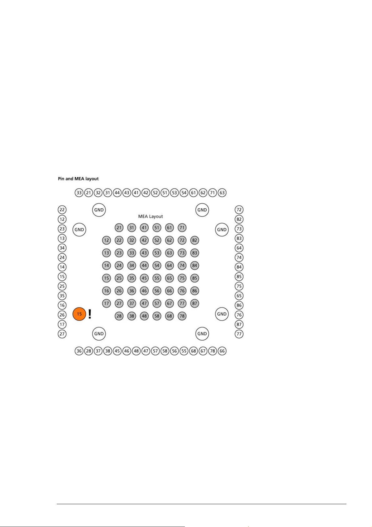
7 Appendix
7.1 Technical Specifications
7.1.1 Pin and MEA Layout
The layout of standard MEA electrodes follows the scheme of a standard grid: The first digit
is the column number, and the second digit is the row number. For example, electrode 23 is
positioned in the third row of the second column. The numbering follows the standard order
from left to right, and from top to bottom.
MEAs are not symmetrical, please pay attention to the recommended orientation of the MEA
chip inside the amplifier: The writing NMI should be on the right side.
The two ground inputs G of the preamplifier are internally connected, so it does not matter,
which one you use.
The following illustration shows the standard pin layout of the socket on the amplifier. The list
below shows the assignment of the electrodes to the pins of the socket. Pin 1 is the ground of the
power supply, pin 2 is the ground of the signal, that is, where the signal is referred to. Both pins
are already internally connected inside the amplifier.
If you are planning to build a custom setup with a home-made filter amplifier, please be careful
with the input of the filter amplifier. Since the MEA1060-BC is a quasi DC-coupled preamplifier,
the input into the filter amplifier has to be AC-coupled, that is, there has to be a capacitor at the
input, before the signal is led into the operational amplifier. Otherwise, you will have problems
with the offset of the metal electrodes, and your filter amplifier will go into saturation.
Channels A1 to A4 (Pin 63 to 66) are the four additional analog inputs of the MCS Standard
Connector that are not used by the MEA amplifier. You can access channels A1 to A3 via the
BNC sockets labeled Analog IN on the rear side of the data acquisition computer of the MEASystem (see also MEA-System manual).
47
Page 52

MEA Amplifier with Blanking Circuit for Inverse Microscopes
Assignment pin to electrode
68-pin socket pin MEA electrode 68-pin socket pin MEA electrode
3 47 33 52
4 48 34 51
5 46 35 53
6 45 36 54
7 38 37 61
8 37 38 62
9 28 39 71
10 36 40 63
11 27 41 72
12 17 42 82
13 26 43 73
14 16 44 83
15 35 45 64
16 25 46 74
17 15 47 84
18 14 48 85
19 24 49 75
20 34 50 65
21 13 51 86
22 23 52 76
23 12 53 87
24 22 54 77
25 33 55 66
26 21 56 78
27 32 57 67
28 31 58 68
29 44 59 55
30 43 60 56
31 41 61 58
32 42 62 57
48
Page 53
7.1.2 MEA1060-Inv-BC
Operating temperature 10 °C to 50 °C
Storage temperature 0 °C to 50 °C
Dimensions (W x D x H) 165 mm x 165 mm x 20 mm (29 mm with sockets)
Weight 800 g
Supply voltage (external power
supply)
Supply current ± 350 mA
Number of stimulus input channels 2
Maximum recommended stimulus
input voltage
Number of analog input channels 60
Input voltage -4 mV to 4 mV
Input impedance
Input noise < 800 nV
Noise density
Number of analog output channels 60
Output voltage ± 5 V
Output current 10 mA
Output impedance
Bandwidth 0.02 Hz to 8500 Hz (Standard total bandwidth MEA1060-
Gain 53 (Standard total gain MEA1060-Inv-BC and standard
Microscope compatibility Inverse microscopes
Distance focal plane to microscope table 3.5 mm
± 6.5 VDC to ± 9 VDC
± 5 V
11
parallel to 10 pF
10
RMS
=
e
n
300
Inv-BC and standard FA60S-BC =1 Hz to 3000 Hz)
FA60S-BC = 1100)
Appendix
49
Page 54
MEA Amplifier with Blanking Circuit for Inverse Microscopes
7.1.3 FA60S-BC
Operating temperature 10 °C to 50 °C
Storage temperature 0 °C to 50 °C
Dimensions (W x D x H) 92 mm x 145 mm x 26 mm
Weight 450 g
Supply voltage (external power
supply)
Supply current ± 200 mA
Number of analog input channels 60
Input voltage 500 mV (with respect to 5 V supply voltage)
Input impedance
Input noise < 1 μV RMS (full bandwidth, inputs short-circuited)
Noise density
Number of analog output channels 60
Output voltage ± 5 V
Output current 10 mA
Output impedance
Bandwidth 8 Hz to 3000 Hz (standard), 1 Hz to 5000 Hz (custom)
Gain 20 (standard), 10 to 100 (custom) (Standard total gain
± 6.5 V to ± 9 V DC
9
parallel to 10 pF
> 10
=
e
n
300
MEA1060-1BC and standard FA60S-BC = 1100)
50
Page 55

7.2 Contact Information
Local retailer
Please see the list of official MCS distributors on the MCS web site.
User forum
The Multi Channel Systems User Forum provides the opportunity for you to exchange your
experience or thoughts with other users worldwide.
Mailing list
If you have subscribed to the Mailing List, you will be automatically informed about new software
releases, upcoming events, and other news on the product line. You can subscribe to the list on
the contact form of the MCS web site.
www.multichannelsystems.com
Appendix
51
Page 56

MEA Amplifier with Blanking Circuit for Inverse Microscopes
7.3 Ordering Information
Product information is subject to change without notice. Please contact your local retailer
for pricing and ordering information.
MEA Amplifiers
Product Product
Number
MEA amplifier for inverted
microscopes
MEA amplifier for upright
microscopes
MEA amplifier with blanking
circuit for inverted microscopes
MEA amplifier with blanking
circuit for upright microscopes
MEA Switch
Product Product
Number
MEA Switch for
4 amplifiers
MEA Switch for
2 amplifiers
MEAS4/2
MEAS2/1
MEA1060-Inv
MEA1060-Up
MEA1060-Inv-BC
MEA1060-Up-BC
Description
The MEA Switch allows you to acquire data from 60 single
channels from two MEA1060 amplifiers. If you have a 128-channel
MC_Card (MEA120-System), you can even pick 128 channels in
total from two MEA pairs with the MEA Switch for four amplifiers
MEAS4/2. The selected channels are combined to one Electrode
Raw Data stream that is delivered to MC_Card by a 68-pin MCS
high grade cable.
Description
Probe interface and 60 channel pre-
and filter amplifier with custom gain
and bandwidth.
Probe interface and 60 channel pre-
and filter amplifier with custom gain and
bandwidth. The blanking circuit prevents
the amplifier from getting saturated and
thus prevents stimulus artifacts.
USB-MEA-Systems
Product Product
Number
USB-MEA-System
for upright
microscopes
USB-MEA-System
for inverted
microscopes
USB-MEA-System
for upright
microscopes with
advanced
perfusion
USBMEA240-Up4-System
USBMEA240-Inv4-System
USBMEA240-Up4-System-E
Description
MEA Workstation for recording and analyzing data from
MEA (microelectrode array) experiments. Data acquisition
from up to 240 MEA electrodes, 4 analog channels, 1 audio
channel, and 16 digital channels. Integrated analog-digital
converter board. The digitally converted electrode signals
are transmitted to any data acquisition computer via USB
2.0 (High Speed). Complete with 5 MEAs, data acquisition
computer with preinstalled software, 4 MEA1060-UpStandard or MEA1060-Inv-Standard amplifiers for upright
or inverted microscopes, 2 temperature controllers, power
supply, and accessories.
MEA Workstation for recording and analyzing data from
MEA (microelectrode array) experiments. Data acquisition
from up to 240 MEA electrodes, 4 analog channels, 1 audio
channel, and 16 digital channels. Integrated analog-digital
converter board. The digitally converted electrode signals
52
Page 57

USB-MEA-System
for inverted
microscopes with
advanced
perfusion
USBMEA240-Inv4-System-E
Appendix
are transmitted to any data acquisition computer via USB
2.0 (High Speed). Complete with 5 MEAs, data acquisition
computer with preinstalled software, 4 MEA1060-Inv
amplifiers for inverted microscopes or 4 MEA1060-Up
amplifiers for upright microscopes, 4 temperature
controllers, 4 perfusion cannulas with programmable fluid
temperature, power supply, and accessories.
USB-MEA-System
with blanking
circuit for upright
microscopes
USB-MEA-System
with blanking
circuit for
inverted
microscopes
USB-MEA-System
with blanking
circuit for upright
microscopes with
advanced
perfusion
USB-MEA-System
with blanking
circuit for
inverted
microscopes with
advanced
perfusion
USBMEA240-Up4-BC-System
USBMEA240-Inv4-BC-System
USBMEA240-Up4-BC-SystemE
USBMEA240-Inv4-BC-SystemE
MEA Workstation for recording and analyzing data from
MEA (micro-electrode array) experiments, featuring
stimulus artifact suppression (blanking), and softwareselectable recording and stimulating electrodes. Data
acquisition from up to 240 MEA electrodes, 4 analog
channels, 1 audio channel, and 16 digital channels.
Integrated analog-digital converter board. The digitally
converted electrode signals are transmitted to any data
acquisition computer via USB 2.0 (High Speed). Complete
with 5 MEAs, data acquisition computer with preinstalled
software, 4 MEA1060-Inv-BC or MEA1060-Up-BC amplifiers
with blanking circuit for upright and inverted microscopes,
2 temperature controller, power supply, and accessories.
MEA Workstation for recording and analyzing data from
MEA (microelectrode array) experiments, featuring stimulus
artifact suppression (blanking), and software-selectable
recording and stimulating electrodes. Data acquisition from
up to 240 MEA electrodes, 4 analog channels, 1 audio
channel, and 16 digital channels. Integrated analog-digital
converter board. The digitally converted electrode signals
are transmitted to any data acquisition computer via USB
2.0 (High Speed). Complete with 5 MEAs, data acquisition
computer with preinstalled software, 4 MEA1060-Inv-BC
amplifiers with blanking circuit for inverted microscopes or
4 MEA1060-Inv-BC amplifiers with blanking circuit for
upright microscopes, 4 temperature controllers, 4 perfusion
cannulas with programmable fluid temperature, power
supply, and accessories.
USB-MEA256System with
integrated data
acquisition and
filter amplifier
USB-MEA256System with
integrated data
acquisition and
filter amplifier,
and advanced
perfusion
USB-MEA32System with
integrated data
acquisition, filter
amplifier, and
stimulus
generator
USBMEA256System
USBMEA256System-E
USB-MEA32STIM4System
256-channel recording system with integrated data
acquisition from 256MEAs. 252 recording channels, and
filter amplification. 4 additional analog and 1 digital I/O
port. Complete with data acquisition computer, software
package and accessories. USB 2.0 High Speed data transfer
with a sampling rate of up to 40 kHz per channel.
256-channel recording system with integrated data
acquisition from 256MEAs.252 recording channels,
4 additional analog and 1 digital I/O port. Complete
with data acquisition computer, software package and
accessories. USB 2.0 High Speed data transfer with a
sampling rate of up to 40 kHz per channel, temperature
controller and perfusion cannula.
32-channel recording system with integrated data
acquisition from perforated MEA-32S12-Lx. 32 recording
channels, 12 stimulation channels, filter amplification and
4-channel current stimulus generator STG, perfusion
cannula PH01 and suction port for low pressure. Complete
with data acquisition computer, software package and
accessories. USB 2.0 High Speed data transfer with a
sampling rate of up to 50 kHz per channel.
53
Page 58

MEA Amplifier with Blanking Circuit for Inverse Microscopes
Accessories
Product Product
Description
Number
Adapter for MEAs with 8
special electrodes for
stimulation
MEASTIMAdapter
For use with MEAs 200/30-Ti-stim or 200/30-ITO-stim,
and MEA1060-Inv amplifier.
Holder with M3 threads MPM3 For fixing tools with M3 threads next to the MEA
1-Channel temperature
controller
2-Channel temperature
TC01
TC02
PID based technology, set-point temperature reached
fast within 30 s to 5 minutes, control temperature range
from ambient temperature to +50 °C
controller
Perfusion cannula with
programmable fluid
PH01 Temperature can be programmed with the temperature
controller TC01 or TC02
temperature
Signal divider for MEASystems
SD-MEA Placed between an MEA1060 amplifier and MC_Card,
permits to select any channel, does not interfere with
the data acquisition, for example, for connecting an
oscilloscope or other devices to single channels
Test Model Probe for
MEA1060 amplifiers
Signal Generator for
MEA1060 amplifiers
Test-MEA Test model probe with CB-GND cable (for ground
connection). For all MEA1060 amplifiers.
MEA-SG Signal generator for MEA Systems: Can be placed in
MEA1060 amplifier. Simulates 12 different types of sine
curves and biological signals.
Signal Generator for USBMEA256-System
256MEASG
Signal generator for USB-MEA256-Systems: Can be
placed in USB-MEA256 amplifier. Simulates 12 different
types of sine curves and biological signals.
Stimulus generators
Product Product
Number
2-Channel stimulus generator STG4002
4-Channel stimulus generator STG4004
8-Channel stimulus generator STG4008
Description
General-purpose stimulus generators for current
and voltage-driven electrical stimulation, 4000
series, with integrated stimulus isolation unit for
each output channel. Operating in Download and
Streaming mode (continuous downstreaming of
pulses from connected computer). MC_Stimulus II
program with advanced features.
54
Page 59

Spare Parts
Appendix
Product Product
Description
Number
Heating element with 8 mm
bore hole
Heating element with 12 mm
bore hole
Heating element with 23 mm
HE-Inv-8
HE-Inv-12
HE-Inv-23
For MEA1060-Inv/MEA1060-Inv-BC
amplifier. Available with bore holes in
different sizes, for using smaller or larger
microscope objectives. The smallest size
has the best temperature controlling
properties.
bore hole
Heating element HE-Up For MEA1060-Up/MEA1060-Up-BC amplifier
Cable assembly CA For HE-Inv or HE-Up
0.5 m 68-Pin MCS Standard cable C68x0.5M
For MEA- or ME-Systems
1 m 68-pin MCS Standard cable C68x1M
3 m 68-Pin MCS Standard cable C68x3M
Ag/AgCl pellet P1060-Inv For MEA1060-Inv/MEA1060-Inv-BC amplifier
Ag/AgCl pellet P1060-Up For MEA1060-Up/MEA1060-Up-BC amplifier
Ag wire W1060-Inv For MEA1060-Inv/MEA1060-Inv-BC amplifier
Ag wire W1060-Up For MEA1060-Up/MEA1060-Up-BC amplifier
Solder lug SL1060-Inv For MEA1060-Inv/MEA1060-Inv-BC amplifier
Gold spring contacts GSC1060-Inv For MEA1060-Inv/MEA1060-Inv-BC amplifier
Gold spring contacts GSC1060-Up For MEA1060-Up/MEA1060-Up-BC amplifier
Gold spring contact comb GSCC1060-Up For MEA1060-Up/MEA1060-Up-BC amplifier
3-Pole cable (from STG to
MEA1060)
Red single pole cable
C3P With ground, not necessary for MEA1060BC
amplifiers
CR
(from STG to MEA1060)
Black single pole cable
CB
(from STG to MEA1060)
55
Page 60

MEA Amplifier with Blanking Circuit for Inverse Microscopes
MEA-Systems
Product Product
Number
MEA recording system
for inverted microscopes,
MEA60-InvSystem
60 electrode channels
MEA recording system
for inverted microscopes,
60 electrode channels,
MEA60-Inv2-System
2 MEA amplifiers
MEA recording system
for upright microscopes,
MEA60-UpSystem
60 electrode channels
MEA recording system
for upright microscopes,
60 electrode channels
MEA recording system
for inverted microscopes
MEA60-Up2-System
MEA60-Inv-
System-E
with advanced perfusion,
60 electrode channels
MEA recording system
for inverted microscopes
with advanced perfusion,
MEA60-Inv-
2-System-E
60 electrode channels
MEA recording system
for upright microscopes
MEA60-Up-
System-E
with advanced perfusion,
60 electrode channels
MEA recording system
for upright microscopes
with advanced perfusion,
MEA60-Up-
2-System-E
60 electrode channels
MEA recording system
for inverted microscopes,
MEA120-Inv-
System
120 electrode channels
MEA recording system
for inverted microscopes,
120 electrode channels
MEA recording system
for upright microscopes,
120 electrode channels
MEA recording system
for upright microscopes,
MEA120-Inv-
4-System
MEA120-Up-
System
MEA120-Up-
4-System
120 electrode channels
Description
Complete with 5 MEAs, data acquisition computer
with MC_Card, MEA1060-Inv amplifier, TC01, power
supply, and accessories
Complete with 5 MEAs, data acquisition computer
with MC_Card, 2 x MEA1060-Inv amplifier, MEAS2/1,
TC02, power supply,
and accessories
Complete with 5 MEAs, data acquisition computer
with MC_Card, MEA1060-Up amplifier, TC01, power
supply, and accessories
Complete with 5 MEAs, data acquisition computer
with MC_Card, 2 x MEA1060-Up amplifier, MEAS2/1,
TC02, power supply,
and accessories
Complete with 5 MEAs, data acquisition computer
with MC_Card, MEA1060-Inv amplifier, TC02, PH01,
power supply, and accessories
Complete with 5 MEAs, data acquisition computer
with MC_Card, 2 x MEA1060-Inv amplifier, MEAS2/1,
2 x TC02, 2 x PH01, power supply, and accessories
Complete with 5 MEAs, data acquisition computer
with MC_Card, MEA1060-Up amplifier, TC02, PH01,
power supply, and accessories
Complete with 5 MEAs, data acquisition computer
with MC_Card, 2 x MEA1060-Up amplifier, 2 x TC02,
2 x PH01, power supply,
and accessories
Complete with 5 MEAs, data acquisition computer
with MC_Card, MEA1060-Inv amplifier, TC02, power
supply, and accessories
Complete with 5 MEAs, data acquisition computer
with MC_Card, 4 x MEA1060-Inv amplifier, MEAS4/2,
2 x TC02, power supply,
and accessories
Complete with 5 MEAs, data acquisition computer
with MC_Card, MEA1060-Up amplifier, TC02, power
supply, and accessories
Complete with 5 MEAs, data acquisition computer
with MC_Card, 4 x MEA1060-Up amplifier, MEAS4/2,
2 x TC02, power supply,
and accessories
56
Page 61

8 Index
57
Page 62

MEA Amplifier with Blanking Circuit for Inverse Microscopes
58
Page 63

3
3D-MEA 35
A
Aliasing 23
B
Band
pass band...........................................23
Bandwidth 23
C
Change MEA 26
COM
serial port ..........................................15
Computer
connection.........................................15
Configuration 7, 29
Connecting 10
Contact Information 51
D
Defective Electrodes
Grounding .........................................27
Delay
Wait settings .....................................32
Download 7
E
EcoMEAs 35
Error Messages 41
F
Faraday cage 10
Filters
bandwidth .........................................23
Frequency
band...................................................23
G
Gain 23
Grounding
Defective Electrodes .........................27
H
Heating 25
I
Installing
Software ..............................................6
IPS10W 10
L
List Mode 7
M
MC_Card 10
MEA
differences in blanking performance35
layout ................................................47
mounting ..........................................26
Mounting
MEA Probe ........................................26
N
Noise
troubleshooting................................ 41
Noise Level
testing ...............................................13
P
Pin
layout ................................................47
R
RS232 15
S
Serial port
connecting ........................................15
Signal
amplification..................................... 23
Signal-to-noise 23
Software
Installing.............................................. 6
Stimulation 29
T
Temperature
connecting the Temperature Controller
........................................................... 10
Temperature control 25
Test Connection 15
Trace List 7, 29
Triggering
blanking ...................................... 15, 32
MC_Rack............................................ 15
stimulation ........................................ 15
TTL
blanking signal .................................32
W
Wait 15, 32
59
Page 64

60
 Loading...