

Page 1
MC_Rack Manual
Page 2

Information in this document is subject to change without notice.
No part of this document may be reproduced or transmitted without the express written
permission of Multi Channel Systems MCS GmbH.
While every precaution has been taken in the preparation of this document, the publisher and
the author assume no responsibility for errors or omissions, or for damages resulting from the use
of information contained in this document or from the use of programs and source code that may
accompany it. In no event shall the publisher and the author be liable for any loss of profit or any
other commercial damage caused or alleged to have been caused directly or indirectly by this
document.
© 2013 Multi Channel Systems MCS GmbH. All rights reserved.
Printed: 09. 09. 2013
Multi Channel Systems
MCS GmbH
Aspenhaustraße 21
72770 Reutlingen
Germany
Fon +49-71 21-90 92 5 - 0
Fax +49-71 21-90 92 5 -11
info@multichannelsystems.com
www.multichannelsystems.com
Microsoft and Windows are registered trademarks of Microsoft Corporation. Products that
are referred to in this document may be either trademarks and/or registered trademarks
of their respective holders and should be noted as such. The publisher and the author
make no claim to these trademark.
Page 3

Table of Contents
Introduction 1
About this Manual 1
Terms of Use 2
Limitation of Liability 2
Important Safety Advice 2
First Use of MC_Rack 3
Welcome to MC_Rack 3
Installing MC_Rack 4
Step by Step Tutorial 7
Using the Step by Step Tutorial 7
Monitoring and Recording Activity 8
Starting MC_Rack 8
Defining the Data Source 9
Advanced Configuration 24
Adding a Data Source 32
Channel Tool 35
Monitoring Activity Continuously 36
Recording Data 42
Starting Data Acquisition and Recording 44
Monitoring and Recording Triggered Activity 45
Triggering MC_Rack on the Stimulus 45
Monitoring Triggered Activity 47
Recording Triggered Data 48
MEA2100-System 51
MEA2100-System 51
Wireless-System 64
Wireless System 64
MC_Rack Features 67
About MC_Rack Features 67
Data Acquisition Settings 67
Data Source Setup 67
Defining Hardware Settings 83
Channel Tool 86
Grouping Multitrode Channels 87
Simulation Mode 87
Data Streams and Channels 90
Data Stream Types 90
Channel Selection 91
Continuous and Triggered Data 92
Averaged Data 94
Digital Data and Binary Code 96
iii
Page 4

MC_Rack Manual
Recorder 97
Replayer 101
Displaying Data 104
Data Display (for Monitoring Raw Data) 111
Digital Display (for Monitoring TTL Inputs) 114
Trigger Detector 115
Automatic Feedback 122
Real-time Feedback 123
Filtering Data 134
Spike Sorter 142
Analyzing Data 152
Recording Data 97
Generating Data Files 99
Loading a Data File 101
File Specifications 102
Replaying Data 102
Display Types 104
Setting up a Display Layout 104
Display Settings 106
Peak Detection 107
Customizing a Display 109
Displaying a Background Picture 109
ASCII Export of Waveforms 110
Plot Types 111
Trace Plot 111
Overlay Plot 111
Raster Plot 112
Displaying Digital Data 114
Numeric Display 114
Using the Manual Trigger 115
Triggering MC_Rack 117
Triggering on TTL Pulses 117
Triggering on Biological Signals 119
Triggering on Extracted Parameters 120
Time Based Trigger 120
Digital Output 122
Real-time Feedback 123
Filtering Data 134
Filter Characteristics 137
Filtering and Sampling Rate 138
Downsampling 140
Spike Detection Methods 142
Detecting Spikes by a Threshold 143
Detecting Spikes by Waveform 143
Spike Cutouts 144
Spike Sorting 145
Burst Analysis 147
Analyzing Data 152
Time-Interval Based Analyzer 153
Event-Based Spike Analyzer 158
iv
Page 5

Table of Contents
Parameter + Spike Analyzer Display 158
Plot Types 158
Trace Plot 158
False Color Maps 159
False Color vs. Time (Plot) 159
False Color Plot 159
Number Plot 160
Parameter/Digital Display Tools + Settings 161
ASCII Export of Extracted Parameters 164
Image Capture 164
Averager 165
Averaging Data Sweeps 165
Sound Output 166
Sound Output with MC_Card 166
Audio Out with USB-ME Data Acquisition 167
Data Export 169
About Data Export 169
Graphs for Presentations 171
Low Resolution Pics (Screen Shots) 171
Working with Graphics Programs 171
Extracting Spikes 172
Spike Sorting 172
General Spike Analysis 173
Analyzing Cardiac Signals 173
Wave Propagation 173
Waveform Shape and QT Interval 174
Extracting Parameters 174
Exporting Parameter Streams to Excel 174
MC_DataTool 174
About MC_DataTool 174
Troubleshooting 175
Technical Support 175
Error Messages 176
Computer Performance 176
Replayer 177
Recorder 178
Running more than one instance of MC_Rack in parallel178
Hardware Errors 178
Data is not Written to Hard Disk 179
Channels Not Visible or Available 179
Appendix 184
Glossary 183
Index 187
v
Page 6

Page 7

1 Introduction
1.1 About this Manual
This manual comprises all important information about MC_Rack. It is assumed that you have
already a basic understanding of technical and software terms, but no special skills are required
to read this manual.
Start practicing with the Tutorial. We offer you the opportunity of Learning by Doing, which
means that you start directly with practicing without much reading beforehand. We suggest that
you start MC_Rack and then follow the Guided Tour step by step, either using the integrated Help
or the printed manual. Just decide what you like to do, read all necessary information in short and
put this information directly into practice.
If you need further information or like to review specific topics as an already experienced user,
please confer to the "MC_Rack Features" part, where you can find more precise information
about all topics.
The printed manual and Help are basically the same, so it is up to you which one you will use.
The Help offers you the advantage of scrolling through the text in a non-linear fashion, picking up
all information you need, especially if you use the Index, and the Search function. If you are
going to read larger text passages, however, you may prefer the printed manual.
The device and the software are part of an ongoing developmental process. Please understand
that the provided documentation is not always up to date. The latest information can be found
in the Help.
1
Page 8

MC_Rack Manual
1.2 Terms of Use
You are free to use MC_Rack for its intended purpose. You agree that you will not decompile,
reverse engineer, or otherwise attempt to discover the source code of the software.
1.3 Limitation of Liability
Multi Channel Systems MCS GmbH makes no guarantee as to the accuracy of any and all tests
and data generated by the use the MC_Rack software. It is up to the user to use good laboratory
practice to establish the validity of his findings.
To the maximum extent permitted by applicable law, in no event shall Multi Channel Systems
MCS GmbH or its suppliers be liable for any special, incidental, indirect, or consequential damages
whatsoever (including, without limitation, injuries, damages for data loss, loss of business profits,
business interruption, loss of business information, or any other pecuniary loss) arising out of the
use of or inability to use MC_Rack or the provision of or failure to provide Support Services, even
if Multi Channel Systems MCS GmbH has been advised of the possibility of such damages.
1.4 Important Safety Advice
Warning: Make sure to read the following advices prior to install or to use MC_Rack. If you do
not fulfill all requirements stated below, this may lead to malfunctions or breakage of connected
hardware, or even fatal injuries. Obey always the rules of local regulations and laws. Only
qualified personnel should be allowed to perform laboratory work. Work according to good
laboratory practice to obtain best results and to minimize risks. Make always sure to validate
your findings. Prepare backup copies on a regular basis to avoid data loss.
The operator is obliged to ensure that MC_Rack is only be used for its intended purpose and that
it is only used by qualified personnel.
MC_Rack is not intended for medical uses and must not be used on humans, especially not for
uses that could impair health.
2
Page 9

2 First Use of MC_Rack
2.1 Welcome to MC_Rack
Please read the following paragraphs to understand the general idea behind the MC_Rack
program before going on with the tutorial or application examples.
MC_Rack is a data acquisition and analysis software. Combined with the hardware, for example
MC_Card, (USB-) ME-Systems or (USB-) MEA-Systems, it forms a complete data acquisition system
for measuring extracellular activities of excitable cells, in vitro and in vivo. It has been developed
especially for use with the (USB-) ME- and the (USB-) MEA-System, but is also ideally suited to
work with other experimental setups.
Together with the data acquisition device, MC_Rack fully replaces a complete hardware set for
data acquisition. For example, you do not need an oscilloscope, a filter, or a spike detector device
anymore, because all this functions are integral part of the software. You set up a virtual
instrument rack, which is comfortable, easy to use, and saves space on your workbench.
The main power of MC_Rack is its great flexibility. You can combine various virtual instruments
according to your experimental setup. You can decide about the fate of each single data stream
separately. It is up to you, which data streams are displayed on the screen, which are saved,
which are analyzed, and so on. This concept saves disk space and computer performance and
makes handling of up to 256 channels with up to 50 kHz sampling rate easy. A status bar
informs you on the actual performance of your computer when you record or replay data.
Please note that the high flexibility of MC_Rack makes a complex configuration of the software
necessary. As a fresh user of MC_Rack, this may present some difficulties to you. But the
straightforward user interface will soon make you feel comfortable with the general concept
and learn to appreciate the advantages of the system. This documentation tries to help you on
your way.
It is very important to note, that all virtual instruments in your rack work independently from
each other. As a consequence, they have to be configured separately. For example, you have to
select the input streams for each instrument separately.
Generally, you will arrange the virtual instruments in your rack in a hierarchical order. The
selected data streams flow from your data acquisition or from the Replayer (recorded data)
into the virtual instrument highest in the hierarchy. Similar to a production line in a plant, this
instrument picks up only those channels from the data streams that you have assigned to it.
It processes this data and produces an output stream, that is lead to the virtual instrument(s) next
in the hierarchy, and so on. When you build a rack, make yourself clear, which data streams flow
to which instrument and what output you should expect. If you change the selection of channels
for a virtual instrument, you may have to adjust the selection for instruments that depend on its
output as well. If you have not specified an input for a tool, an error message will inform you.
In MC_Rack, the rack you use to record and analyze data online and offline, and the data files are
as a matter of principle independent from each other. You can save and reuse a rack for several
experiments and generate separate data files. You can then load the generated data file with
another rack for further offline analysis later.
3
Page 10

MC_Rack Manual
The MC_Rack help is divided into the following main sections:
Step by Step Tutorial: The tutorial introduces basic MC_Rack features for directly setting up
a basic experiment.
MEA (In Vitro) Application Examples (please see separate document): Main MC_Rack features
are explained in detail on the basis of typical applications and demo data files. We
recommend to study especially the applications that you are interested in before starting an
experiment, so that you learn about the possibilities and how to configure MC_Rack for different
applications. This section is more detailed than the tutorial. Also, it is easier to understand the
software features when playing around with demo data.
MC_Rack Features: All MC_Rack features are explained in detail. This section is especially useful
if you want to learn more about a specific software feature.
Data Export: Summarizes the export options of MC_Rack and MC_DataTool and provides
recommendations for third party programs for offline data analysis.
Troubleshooting: Lists typical minor problems that might occur during operation and gives hints
how to solve them.
2.2 Installing MC_Rack
The data acquisition computer with the data acquisition device, for example MC_Card or USBMEA256, comes preinstalled and preconfigured by MCS for a flawless operation. You should
contact your local retailer for assistance if you want to install additional hard- or software, or
if you want to replace the computer, as incompatibilities of hardware components or software
settings with MC_Rack may occur.
Caution: You have acquired a high performance data acquisition and analysis computer. Do not
modify the system, do not install new hard- or software, or another operating system without
asking MCS or your local retailer for advice. Especially do not install virus scanners or firewalls
because these programs are known to interfere with the data transfer to the hard disk. MCS
cannot guarantee that a modified system is fully operational. Even data loss may occur.
System requirements
Software:
One of the following Microsoft Windows ® operating systems is required: Windows 7, Vista,
or XP (English and German versions supported) with the NT file system (NTFS). Other language
versions may lead to software errors.
Hardware:
The data acquisition board MC_Card. (Not required for offline analysis or demo mode). If no
MC_Card is present, MC_Rack opens in a simulation mode. A computer with low performance
may lead to performance limits more often; therefore, MCS recommends an up-to-date computer.
Please note that there are sometimes hardware incompatibilities of the MC_Card and computer
components; or that an inappropriate computer power supply may lead to artifact signals.
Please contact your local retailer for more information on recommended computer hardware.
The USB-ME-Systems or the USB-MEA-Systems. (Not required for offline analysis or demo
mode). The USB based data acquisition systems do not need the MC_Card. These systems are
equipped with an internal data acquisition. The analog input signals from up to 256 channels
are acquired and digitized by the systems and the digital electrode signals are transmitted to
the connected computer via universal serial bus (High Speed USB 2.0).
Important: You need to have installed the latest driver to operate the data acquisition device,
which is automatically installed with MC_Rack. The installation may be invalid if the data
acquisition device does not respond. Please contact Multi Channel Systems or your local retailer
in this case.
4
Page 11

First Use of MC_Rack
Recommended operating system settings
The following automatic services of the Windows operating system interfere with the data
storage on the hard disk and can lead to severe performance limits in MC_Rack. These routines
were designed for use on office computers, but are not very useful for a data acquisition
computer.
Turn off Windows System Restore.
Turn off automatic Windows Update.
Windows Indexing Service deselected for all local disks.
Optimize hard disk when idle (automatic disk fragmentation) turn off.
It is also not recommended to run any applications in the background when using MC_Rack.
Remove all applications from the Autostart folder.
Be careful when using a Virus Scanner. These programs are known to disturb MC_Rack,
and even data loss may occur.
When using an USB-ME-System or an USB-MEA-System it is recommended to connect
a high performance computer with a separate hard discs for program files and data storage.
The provided possibility to use up to 256 channels with a sample rate of up to 40 kHz needs high
memory capacity. Please remove data and defragment the hard disc regularly to ensure optimal
performance.
Warning: The operating system settings of the data acquisition computer were preconfigured
by MCS and should not be changed by the user. Changing these settings can lead to program
instabilities and data loss.
Switching on the connected computer
(Applicable only if you use a data acquisition computer from Multi Channel Systems.)
1. Power up the connected computer and wait until it is ready. The Login dialog box appears.
2. Enter "mcs" both as the user name and as the user password. You do not have to enter an
administrator password. (You may change the passwords later, of course.) The Windows desktop
is displayed.
Installing the software
Please check the system requirements before you install the software. MCS cannot guarantee that
the software works properly if these requirements are not fulfilled.
Important: Please make sure that you have full control over your computer as an administrator.
Otherwise, it is possible that the installed software does not work properly.
1. Double-click Setup.exe on the installation volume. The installation assistant will show up
and guide you through the installation procedure.
2. Follow the instructions of the installation assistant. The hardware driver and MC_Rack are
installed (or updated) automatically.
5
Page 12

Page 13

3 Step by Step Tutorial
3.1 Using the Step by Step Tutorial
In the following tutorial, you will set up virtual racks for different applications from scratch.
The goal is that you learn about MC_Rack features by doing. The racks are quite simple to give
you an idea of the software's philosophy and how things work. All racks described in the tutorial
are also available on the installation volume. So, if you prefer to start with a preconfigured rack,
you can load the rack of interest first, and then go through this tutorial to see how to adapt the
rack's settings and parameters to your needs, but we recommend that you take a bit time to build
it yourself to learn the principle of operation.
Both racks discussed in the Step by Step Tutorial are basic racks for monitoring and recording
data. The only difference is, that Monitoring and Recording Activity Continuously describes how
to monitor and record activity continuously (generally used for spontaneous activity). Monitoring
and Recording Triggered Activity describes how to monitor and record activity triggered by an
event, that is, for evoked responses, for example, in an LTP experiment. All important information
is repeated in each section, so you may freely choose the rack that is suitable for your application
without missing information.
The difference to the MEA application examples (see separate document) is that the racks that
we set up in this tutorial can be used directly in a real experiment. Without demo data, they may
appear somehow a bit abstract. If you are new to the extracellular recording technique and want
to get an impression how MC_Rack works and how signals can look like, you may prefer to have a
look at the MEA application examples and demo racks first. Also, in the MEA application examples
section, more advanced MC_Rack features are explained in detail and very near to the application.
You will find a list and a short description of all sample racks in the MC_Rack Sample Racks topic.
The MEA Signal Generator
The MEA Signal Generator MEA–SG is a convenient tool for MEA-Systems first time users.
The device has the same dimensions and connector layout as a 60-channel MEA chip and is
compatible with all MEA1060 amplifier types and with the MEA2100-60 / MEA2100-2x60-Systems.
The MEA–SG can produce sine waves, or replay a variety of biological signals. These signals are
fed into the MEA amplifier as analog signals. With this artificial data, you are able to test the
functionality of the hardware and software system, without the need for a biological sample.
Please use the 256MEA-SG for the USB-MEA256-System and the 120MEA-SG for MEA2100-120Systems..
7
Page 14
MC_Rack Manual
3.2 Monitoring and Recording Activity
3.2.1 Starting MC_Rack
Double-click the MC_Rack icon or select MC_Rack from the Start menu.
The program starts. One window opens automatically. This is your virtual rack configuration,
which is blank after program start. Therefore, most commands and buttons are unavailable.
You can choose from various software features, so-called virtual instruments, and assemble the
virtual rack according to your specific application. You will learn in this tutorial how to set up
racks for some typical applications.
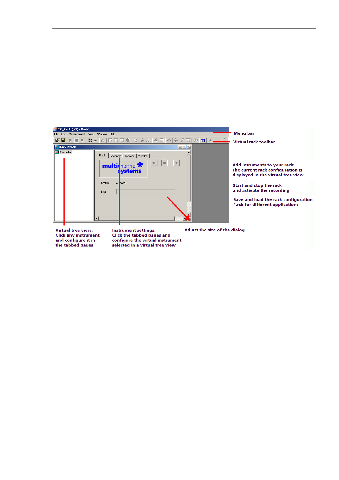
MC_Rack main window (empty)
The virtual rack
The title bar shows the file name of the virtual rack (the default name before saving the rack
under a custom name is Rack1). The white pane on the left of the virtual rack window holds the
virtual rack tree view pane, where all virtual instruments that are part of this rack are
represented by icons and (customizable) individual instrument names.
After program start, the virtual rack is almost empty, it holds only a single virtual instrument the
Recorder, represented by a small cassette player icon. The context-sensitive grey pane on the
right shows the virtual instrument settings (organized in tab pages) of the virtual instrument
that is selected (highlighted in blue) in the virtual rack tree view pane on the left. If you have
added more instruments to the rack, you were able to click through the instruments in the tree
view pane, and click the tabbed pages to review or change any settings.
At this point, only the Recorder settings are available. The first Rack tabbed page is always the
same for all virtual instruments here, you can start and stop MC_Rack (that is, the data
acquisition or the Replayer), and activate the recording (that is, writing data to hard disk).
The Lag status bar gives you information on the computer performance; the lower the Lag, the
better the performance. When the Lag exceeds the maximum, MC_Rack will be stopped
automatically, and you will be informed about a performance limit of the computer by an error
message. The complexity limit of the virtual rack depends directly on the computer performance.
To avoid data loss during over night recordings, for example, test the rack configuration
thoroughly under realistic conditions (that is, the signal rate should be as expected in the real
experiment) before starting the experiment. If you have trouble with the computer performance,
please see the chapter Error Messages in the Troubleshooting section for more information on
how to optimize the rack configuration.
8
Page 15
Step by Step Tutorial
In the Recorder settings, you select the data streams and channels that you want to save to the
hard disk. You define the path and the file in which the acquired data will be saved, and you
define other parameters like the recording mode (continuous or triggered), and the maximum
file size.
The Recorder shows you the currently available disk space on the target hard disk. Please check
the disk space and estimate how long you still can write data to the hard disk always before
starting an experiment. Otherwise, data loss will occur when the disk is full. For example, if you
record 60 electrode channels at a sampling frequency of 25 kHz, the data rate is 3 MB/s, that is
10.8 GB/h.
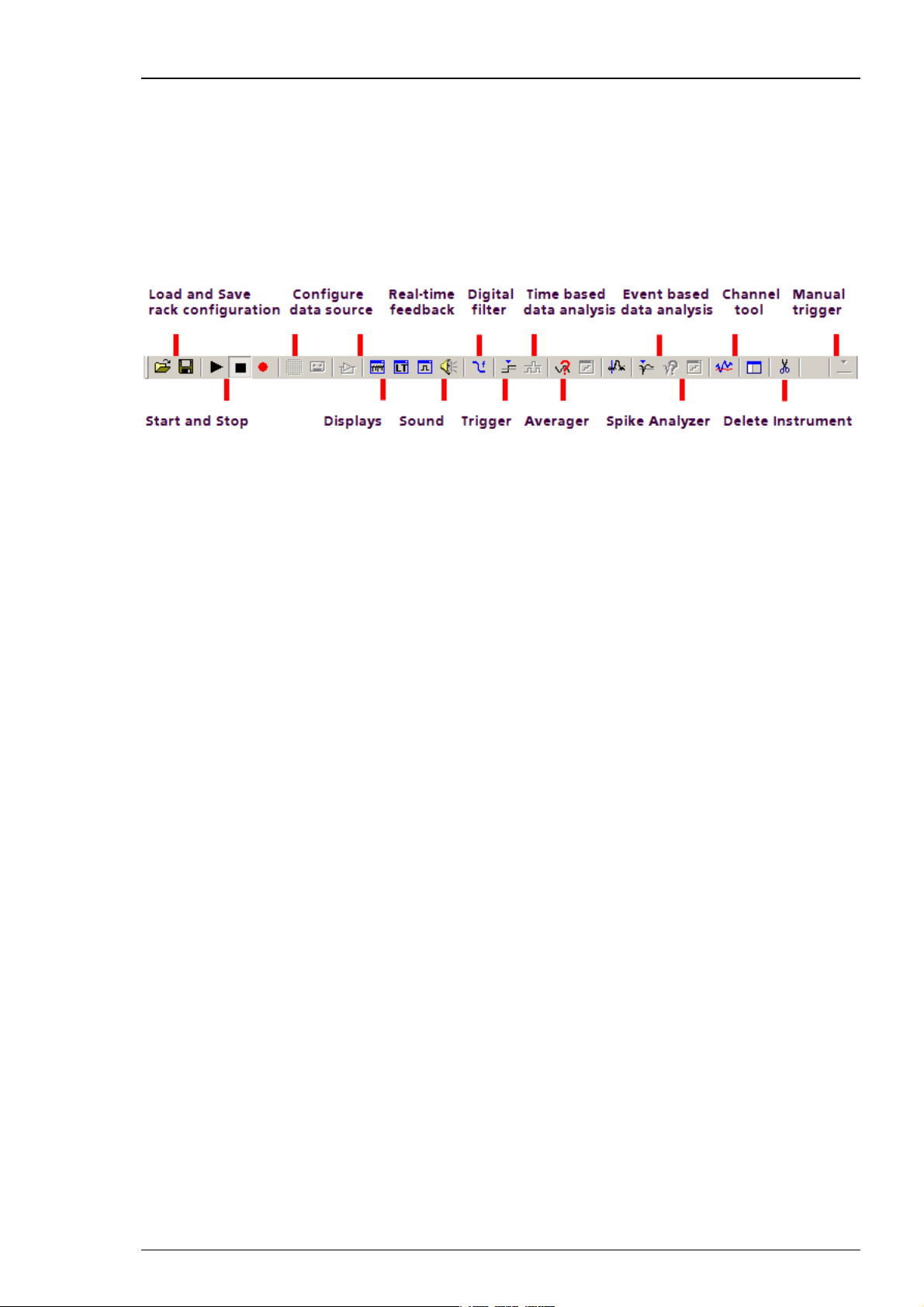
MC_Rack toolbar. For a more detailed information on the toolbar buttons, please see "Toolbar"
under General User Interface.
The MC_Rack toolbar shows all main functions available in MC_Rack. You can click on a virtual
instrument button to insert a virtual instrument into your rack configuration. Please note that
virtual instruments that need an input data stream that is generated by another virtual
instrument (for example, the Spike Analyzer, which needs a Spike data stream generated by
the Spike Sorter) can only be placed in series with the required virtual instrument and are
otherwise not available (indicated by a gray button color). In an empty rack, only the data source,
that is, the data acquisition or the replayer, are available to start with. After the data source
was inserted into the rack, other virtual instruments will be available.
3.2.2 Defining the Data Source
MC_Rack is the universal data analysis program for all ME- and MEA-Systems with PCI card as
well as with USB based data acquisition. To ensure correct display of the data of your system,
it is therefore necessary to configure the data source accordingly. This has to be done only once
for a given rack. See the MEA-System manual or the ME-System manual for the MC_Rack features
that are supported by your system.
On the Edit menu, click Data Source Setup to configure the software according to your data
acquisition and amplifier hardware. Data Source Setup is only available as long as no data
source is included in a new rack file. Configure the channel layout first and then set up the
rack for your experiment. The data source setup and channel layout information is saved
together with the rack.
9
Page 16
MC_Rack Manual
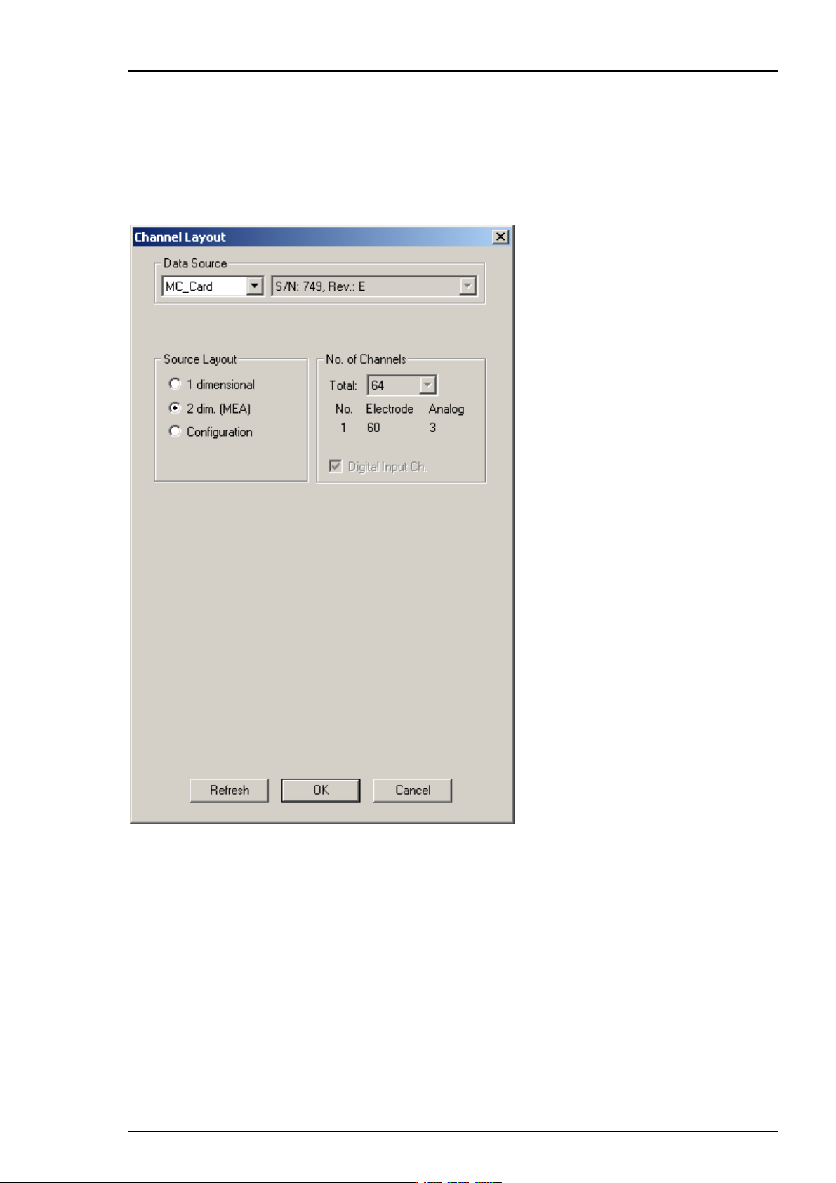
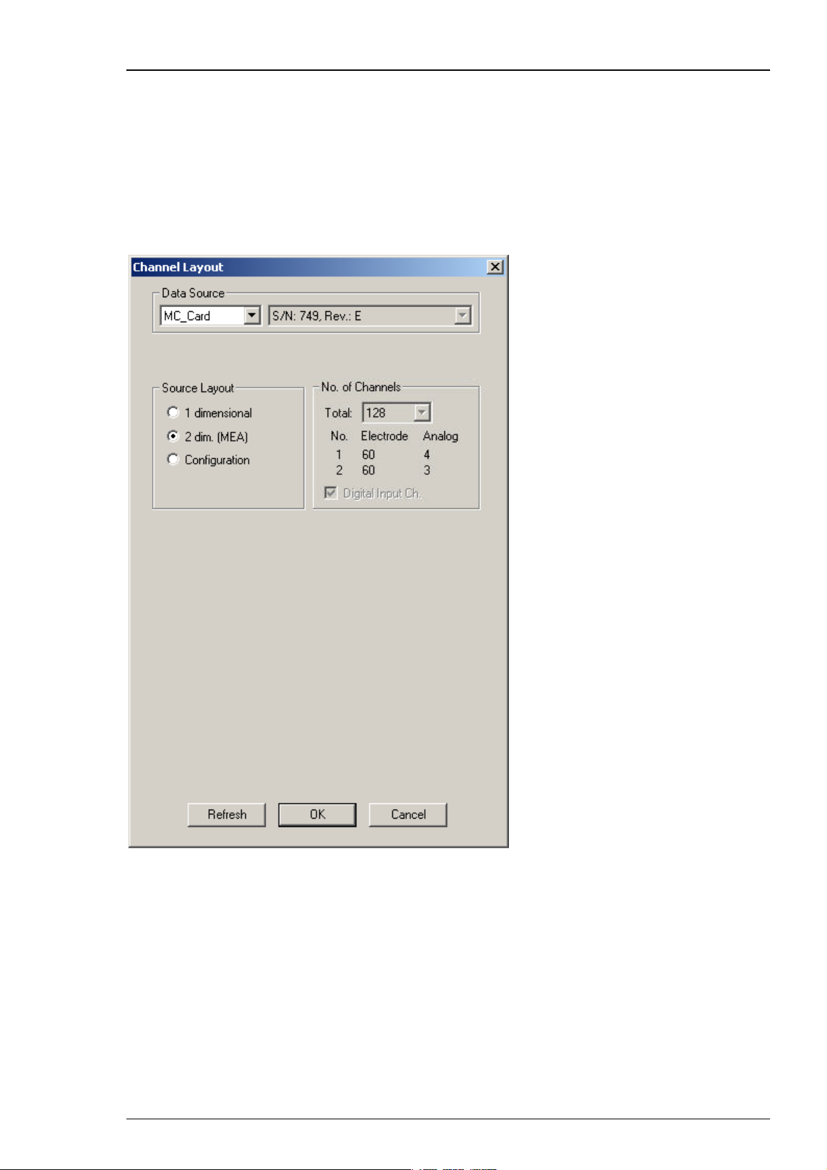
MEA60-System
Select 2 dimensional (MEA) if you are performing extracellular recordings from microelectrode
arrays (MEA) with a MEA60-System with 60 electrode channels. The number and layout of
channels is pre-configured and cannot be altered. You have three additional analog channels
(A1, A2, A3), and an additional 16-bit digital channel available. The standard BNC connectors for
the digital channel on the data acquisition computer support only three digital input bits (0, 1, 2).
A digital IN / OUT extension is available that supports all 16 digital in- and output bits.
10
Page 17
Step by Step Tutorial
MEA120-System
Select 2 dimensional ( MEA) if you are performing extracellular recordings from microelectrode
arrays (MEA) with a MEA120-System with 120 electrode channels. The number and layout of
channels is pre-configured and cannot be altered. The MC_Card supports seven additional analog
channels, but the BNC connectors on the data acquisition computer support only 3 additional
analog channels (A1, A2, A3). You have an additional 16-bit digital channel available. The
standard BNC connectors for the digital channel on the data acquisition computer support only
three digital input bits (0, 1, 2). A digital IN/OUT extension is available that supports all 16 digital
in-and output bits.
11
Page 18
MC_Rack Manual
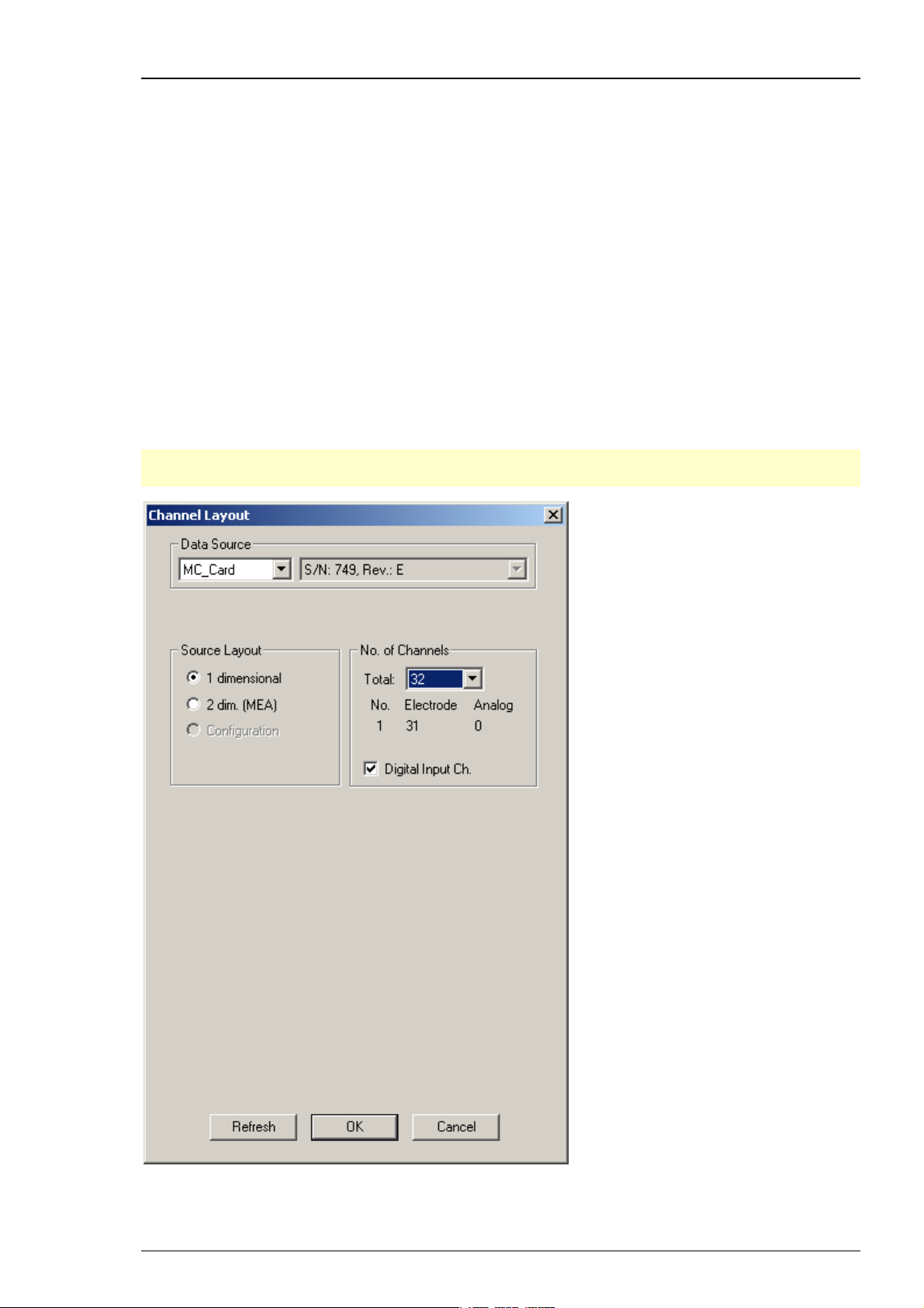
ME-Systems
Select 1 dimensional if you are using a ME-System (generally used for in vivo or special in vitro
applications). ME-Systems are available with different channel numbers. Define the number
of channels provided by the data acquisition (MC_Card or USB-ME), and specify how many
electrodes (data amplified by the main amplifiers, for example, a MPA and a following filter
amplifier) and how many analog inputs (for example, from a temperature controller or
a microphone) are present. For the electrode channels, the original signal is calculated
automatically according to the gain settings in MC_Rack. Signals on the analog channels
are recorded "as is", with no respect to the gain.
Deselect the option Digital Input Channel, if you do not want to use the digital input channel.
One of the digital input bits can be used for triggering the recording on a TTL output of the
stimulator, for example. A typical configuration of a ME64-System would be 63 electrodes and
a digital channel. Please note that the use of the digital input channel is available on the cost
of an analog channel, that is, if you have an ME16-System and want to use the digital channel,
for example for synchronizing stimulation and recording, you could only use a maximum of 15
electrode channels. Make sure that you select the digital channel if you want to trigger the data
analysis and/or the recording.
Hint: Deselect the option Digital Input Channel, if you do not need a digital channel. Otherwise
the number of electrode recording channels is reduced by 1!
12
Page 19
Step by Step Tutorial
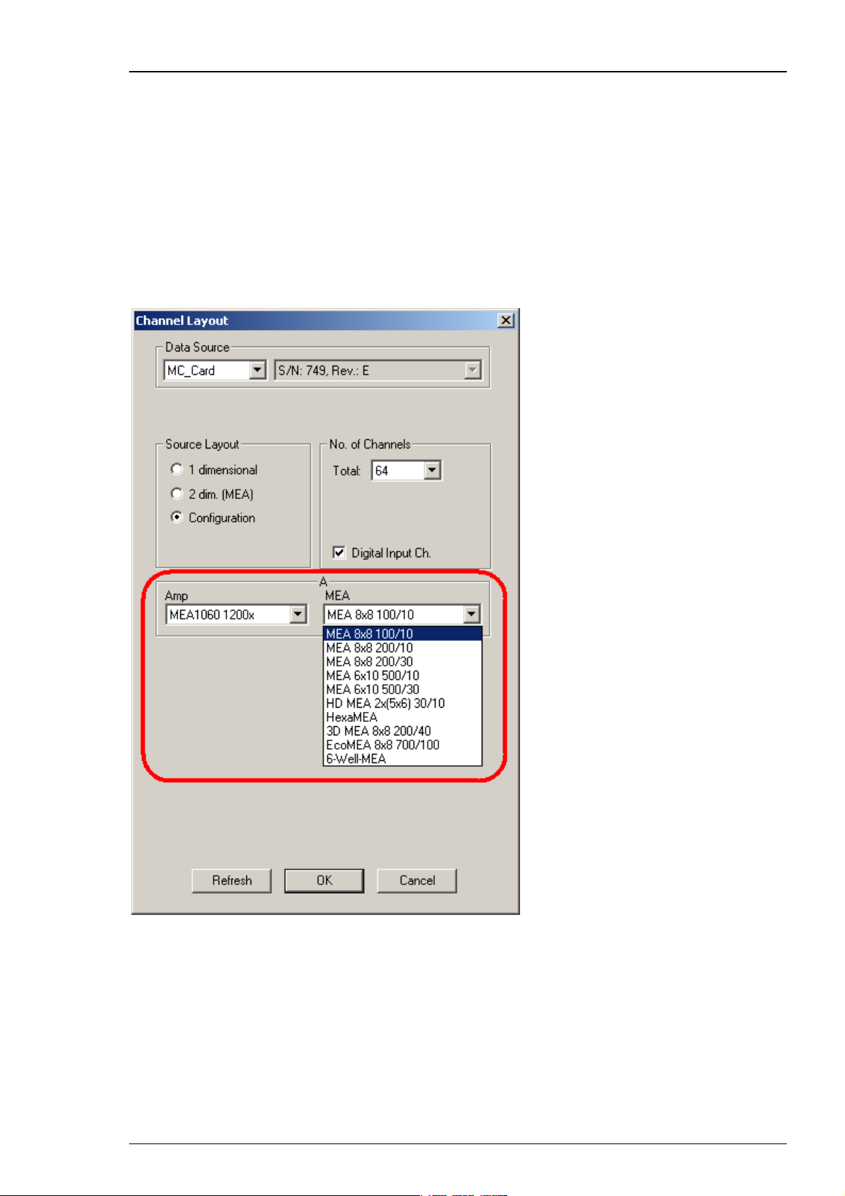
Data Source Configuration
Click "Configuration".
Configuration is an option that can also be used with MC_Card data acquisition (64 or 128
channels), but is recommended for the USB based data acquisition systems USB-ME64 / USBME/128 / USB-ME256 or MEA2100-System. When selecting the configuration option, it is first
necessary to adjust the number of channels available. After that you can select the amplifier(s)
and MEA(s) in use from a drop down menu. To configure the MEA layout, please use the right
drop down menu "MEA". To configure the amplifier, please use the left drop down menu "Amp"
(MEA1060 without blanking circuit, gain factor 1200, and MEA1060BC with blanking circuit, gain
factor 1100 for MEA-Systems, and FA64I/S, FA32I/S for ME-Systems, MEA2100-H60 or MEA2100H120 for MEA2100-System).
13
Page 20
MC_Rack Manual
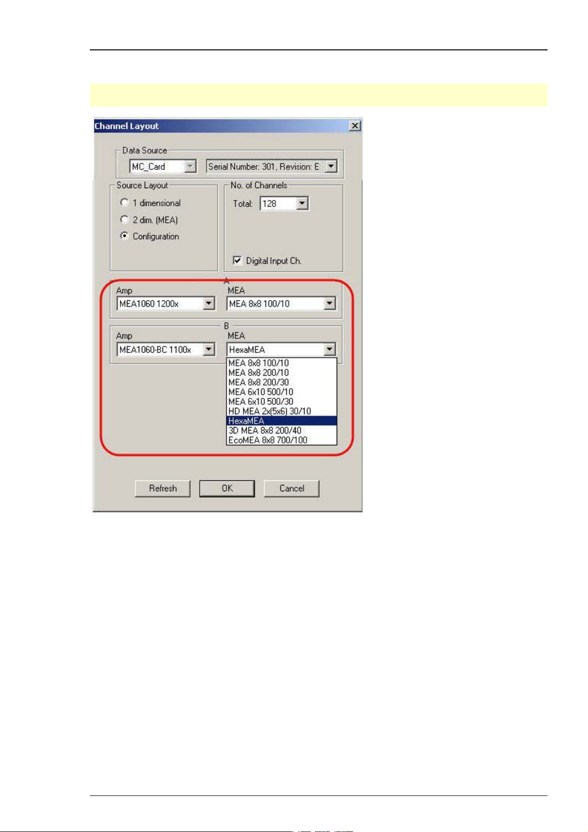
In MEA120-System it is possible to configure both amplifiers independent of each other.
Additionally it is possible to configure the MEA layouts of MEA A and MEA B individually.
Note: Setting up the configuration of the data source is important for having the correct layouts
for MEA A and MEA B during the complete experiment.
14
Page 21

Step by Step Tutorial
USB-ME16-FAI-System
The USB-ME16-FAI System does not require a MC_Card, but uses an internal data acquisition.
Data can be transferred via USB 2.0 port to any data acquisition computer. Please see USB-ME16FAI Manual for detailed information. Select USB-MEA from the left Data Source drop down list.
The USB-MEA device will be specified on the right Data Source drop down menu: USB-ME16 (S/N:
00001). The number in brackets is the serial number of the device. The data source layout is 1
dimensional, with 16 electrode channels, and an additional digital channel.
15
Page 22

MC_Rack Manual
USB-ME32-FAI-System
The USB-ME32-FAI System does not require a MC_Card, but uses an internal data acquisition. Data
can be transferred via USB 2.0 port to any computer. Please see USB-ME32-FAI Manual for detailed
information. Select USB-MEA from the left Data Source drop down list. The USB-MEA device will
be specified on the right Data Source drop down menu: USB-ME32 (S/N: 00001). The number in
brackets is the serial number of the device. The data source layout is 1 dimensional, with
32 electrode channels, and an additional digital channel.
16
Page 23

Step by Step Tutorial
USB-ME64 / USB-ME128 / USB-ME256 Data Acquisition
The USB-ME64 / 128 / 256 data acquisition systems are in principle the same devices, except
for the total number of channels.
USB-ME256 Data Acquisition
The USB-ME256 is an external data acquisition device that uses USB 2.0 connection to transfer
digitized data to any connected computer. Please see USB-ME256-System manual for detailed
information. Select USB-MEA from the left Data Source drop down list. The USB MEA device
will be specified on the right Data Source drop down menu: USB-ME256 (S/N: 0004). The number
in brackets is the serial number of the device. Adjust the number of channels available.
17
Page 24
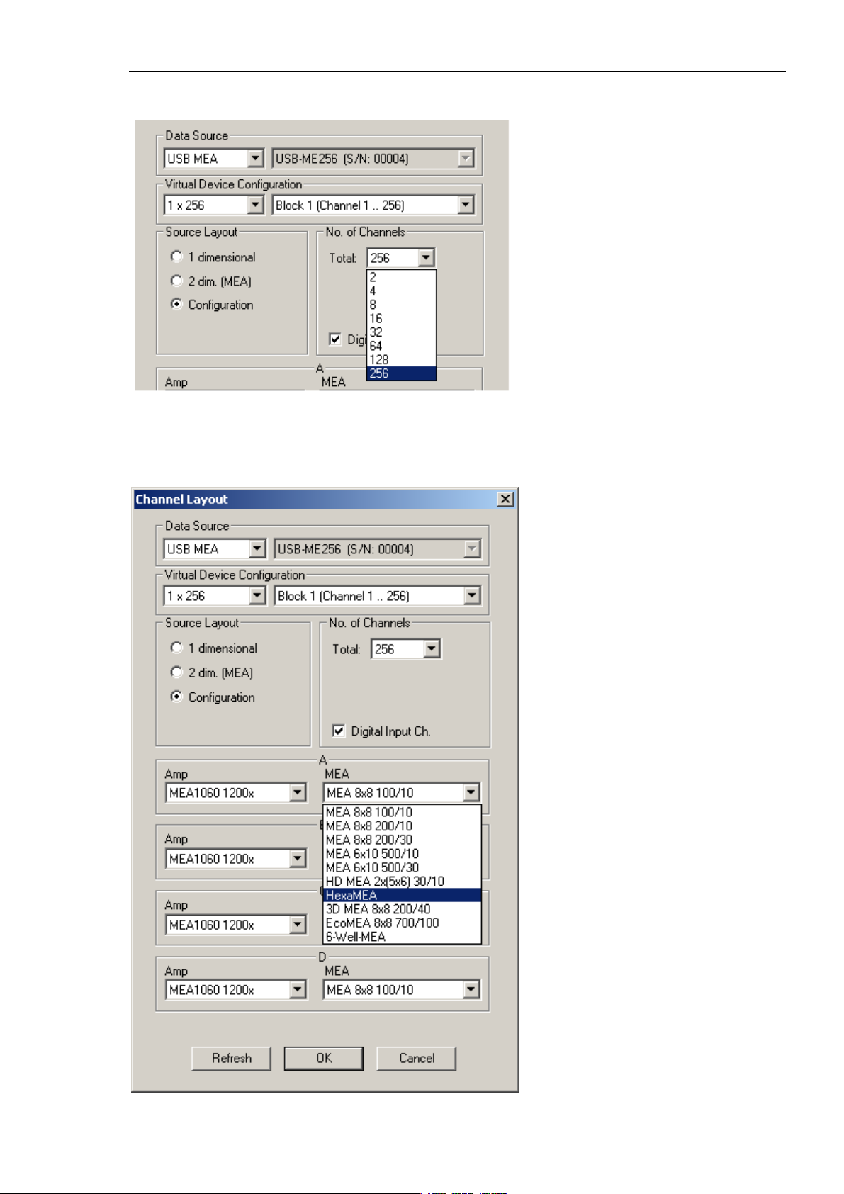
MC_Rack Manual
Click Configuration in Source Layout. Choose 256 as total number of channels from the drop down
list under No. of Channels.
In USB-ME256-System it is possible to configure four MEA1060 / MEA1060BC amplifiers
independent of each other. Click the Amplifier drop down menus on the left side. Additionally
it is possible to configure the MEA layouts for up to four MEAs A and B, C and D independent
of each other. Click the MEA drop down menus on the right side.
18
Page 25

Step by Step Tutorial
On the Edit menu, click Advanced Configuration to configure the software according to the
USB-ME256 hardware. Please see Advanced Configuration for detailed information. The dialog
Advanced Configuration is for optionally defining as many instances of MC_Rack software
as necessary. That means, you are able to work with several MC_Rack versions in parallel, for
example, when using the USB-ME256 with up to four MEA1060 amplifiers. With setting "Max.
Number of MC_Rack Instances = 4" in Advanced Configuration you can control each of the four
amplifiers independent from the others with its own MC_Rack software.
Note: Setting up the configuration of the data source is important for having the correct layouts
for MEA A, B, C and D during the complete experiment.
USB-ME128 Data Acquisition
The USB-ME128 device is in principle the same device as the USB-ME256, except for the total
number of channels, that is 128.
The USB-ME128 is an external data acquisition device that uses USB 2.0 connection to transfer
digitized data to any connected computer. Please see USB-ME128 Manual for detailed
information. Select USB MEA from the Data Source drop down list. The USB MEA device will
be specified on the right Data Source drop down menu: USB-ME128 (S/N: 0002), for example.
The number in brackets is the serial number of the device.
In USB-ME128-System it is possible to configure two MEA1060 / MEA1060BC amplifiers
independent of each other. Additionally it is possible to configure the MEA layouts for MEA A
and MEA B independent of each other.
On the Edit menu, click Advanced Configuration to configure the software according to the
USB-ME128 hardware. The dialog Advanced Configuration is for optionally defining as many
instances of MC_Rack software as necessary. That means, you are able to work with several
MC_Rack versions in parallel, for example, when using the USB-ME128 with two MEA1060
amplifiers. With setting "Max. Number of MC_Rack Instances = 2" in Advanced Configuration
you can control each of the two amplifiers independent from the other with its own MC_Rack
software.
Note: Setting up the configuration of the data source is important for having the correct layouts
for MEA A and B during the complete experiment.
USB-ME64 Data Acquisition
The USB-ME64 device is in principle the same device as the USB-ME256, except for the total
number of channels, that is 64.
The USB-ME64 is an external data acquisition device that uses USB 2.0 connection to transfer
digitized data to any connected computer. Please see USB-ME64 Manual for detailed information.
Select USB MEA from the Data Source drop down list. The USB MEA device will be specified on
the right Data Source drop down menu: USB-ME64 (S/N: 0002), for example. The number in
brackets is the serial number of the device.
In USB-ME64-System it is possible to configure the MEA1060 / MEA1060BC amplifier. Additionally
it is possible to configure the layout of MEA A.
Note: Setting up the configuration of the data source is important for having the correct layout
for MEA A during the complete experiment.
19
Page 26

MC_Rack Manual
USB-MEA256 Data Acquisition and Filter Amplification
The USB-MEA256 is an external data acquisition device with integrated filter amplifier that uses
USB 2.0 connection to transfer digitized data to any connected computer. Please see USB-MEA256
Manual for detailed information. Select USB-MEA from the left Data Source drop down list.
The USB-MEA device will be specified on the right Data Source drop down menu: USB-MEA256
(S/N: 00007). The number in brackets is the serial number of the device.
20
Page 27
Step by Step Tutorial
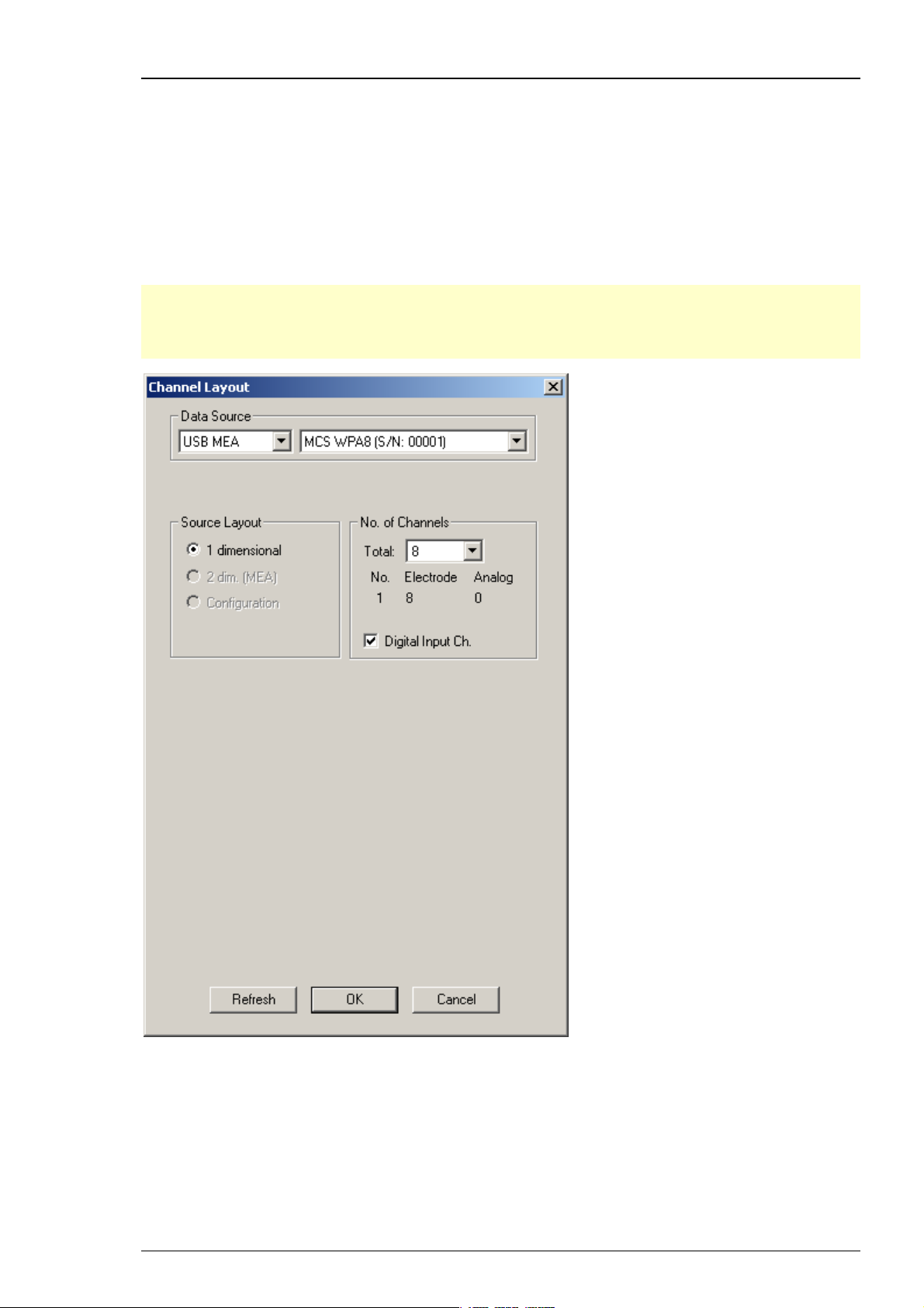
Wireless Recording System
The wireless in vivo recording system is the all-in one solution for amplifying, recording, and
analyzing in vivo data from eight channels that uses a wireless connection between headstage
and receiver and an USB 2.0 connection to transfer digitized data to any connected computer.
Please read the Wireless-System manual for detailed information. Select USB MEA from the left
Data Source drop down list. The wireless system device, W8 for example, will be specified on the
right Data Source drop down menu: MCS WPA8 (S/N: 00001). The number in brackets is the serial
number of the system. The data source layout is 1 dimensional, with 8 electrode channels and an
additional digital channel.
Note: With all electrode channels, the maximum sampling rate for the 8-channel Wireless
Recording System W8-System is 20 kHz. It is possible to increase the maximum sampling rate
up to 40 kHz by deactivating at least four electrode channels. Please pay attention to the
sampling rate respectively, when using the W4-, W16- or W32-System.
21
Page 28

MC_Rack Manual
MEA2100-System
The MEA2100 recording system is an all-in one solution consisting of headstage and interface
board. The MEA2100-System with integrated amplification, data acquisition, online signal
processing, and integrated stimulus generator. You can connect one or two headstages to
the interface board. The MEA2100-System uses an USB 2.0 connector per headstage to transfer
digitized data to any computer. Please read the MEA2100-System manual for detailed
information. Please read also chapter "Data Source Setup" in "MEA2100-System".
Select USB MEA from the left Data Source drop down list. The MEA2100 device will be specified
on the right Data Source drop down menu: MEA2100 (S/N: 0000-A).The number in brackets is
the serial number of the system, the character A labels the connected headstage, A is the first
headstage, B is the second headstage. It is possible to run up to two instances of MC_Rack per
headstage. Please read chapter "Advanced Configuration". Specify the “Number of Channels”
first: 32 electrode channels, when connecting one headstage with 32 recording and 12 stimulation
electrodes (MEA2100-HS32), 64 when connecting one headstage with 60 channels (MEA2100HS60) or 128 electrode channels when connecting two headstages with 60 channels (MEA2100HS60) or one headstage with 120 channels (MEA2100-HS2x60 or MEA2100-HS120) to the interface
board. Choose “Configuration” in the data source layout. Enable the check box for the digital
input channels. Select the correct headstage in the “Amplifier” drop down menu and specify
the type of MEA.
22
Page 29

Step by Step Tutorial
In MEA2100-System it is possible to configure two headstages independent of each other.
MC_Rack identifies two connected headstages as completely different devices. They are defined
via the character A or B in the serial number in the right "Data Source" drop down menu.
It is also possible to run two MC_Rack instances per headstage, for example for recording
from the 2x60 channels of the MEA2100-HS2x60 headstage separately. Please read chapter
"Advanced Configuration". Click the Amplifier drop down menus on the left side to configure
the "Amplifier". Additionally it is possible to configure the MEA layouts for up to two MEAs A
and B independent of each other. Click the MEA drop down menus on the right side.
MEA2100-32-System
The MEA2100-32-System is a descendant of the MEA2100-System with the same functions except
of the real-time feedback. Please read the MEA2100 Manual for detailed information. Select USB
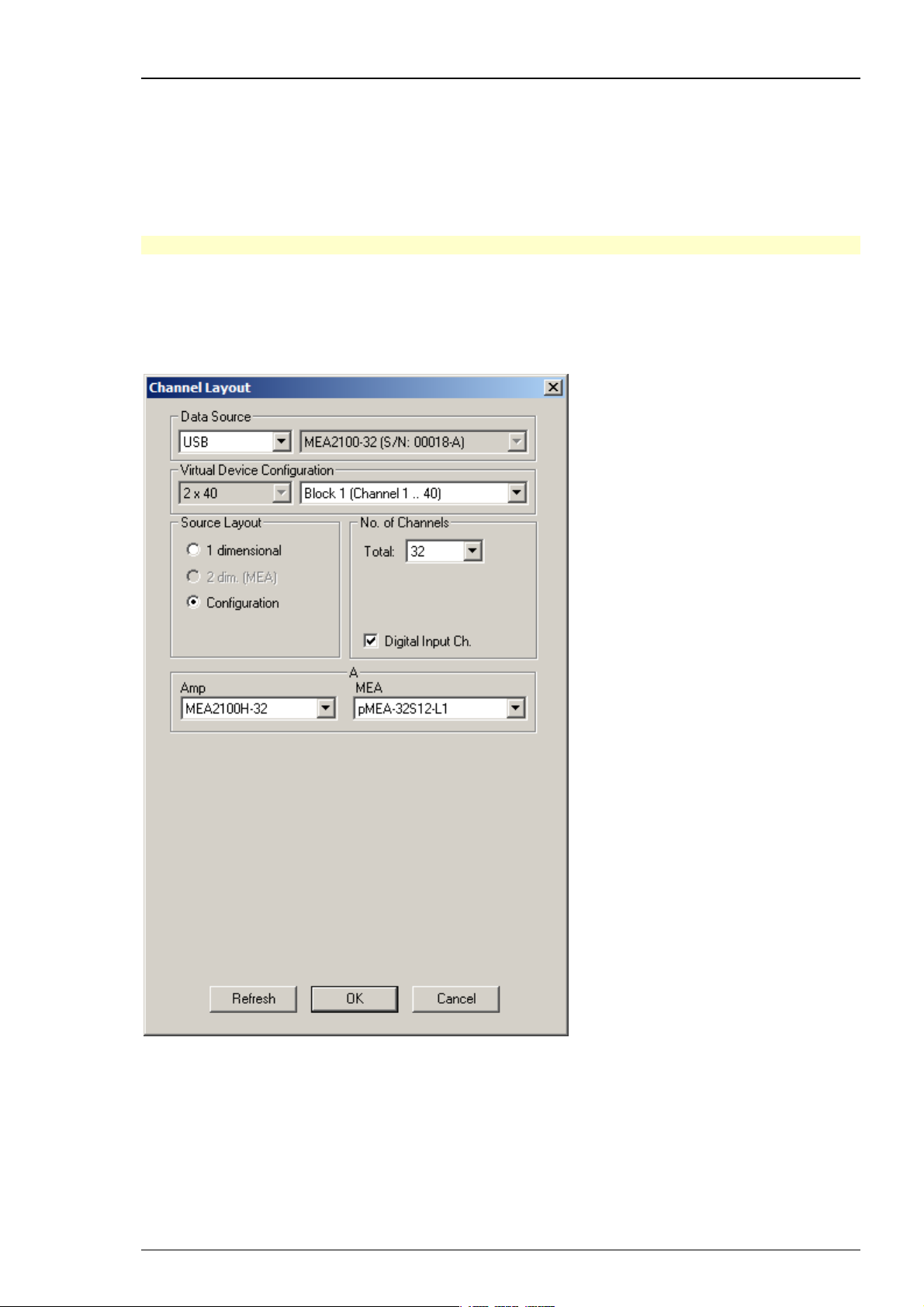
from the left Data Source drop down list. The MEA2100-32 device will be specified on the right
Data Source drop down menu: MEA2100-32 (S/N: 00018-A). The number in brackets is the serial
number of the device. The data source layout is Configuration, with 32 electrode channels. It does
not matter whether you select the digital input channel or not.
23
Page 30
MC_Rack Manual
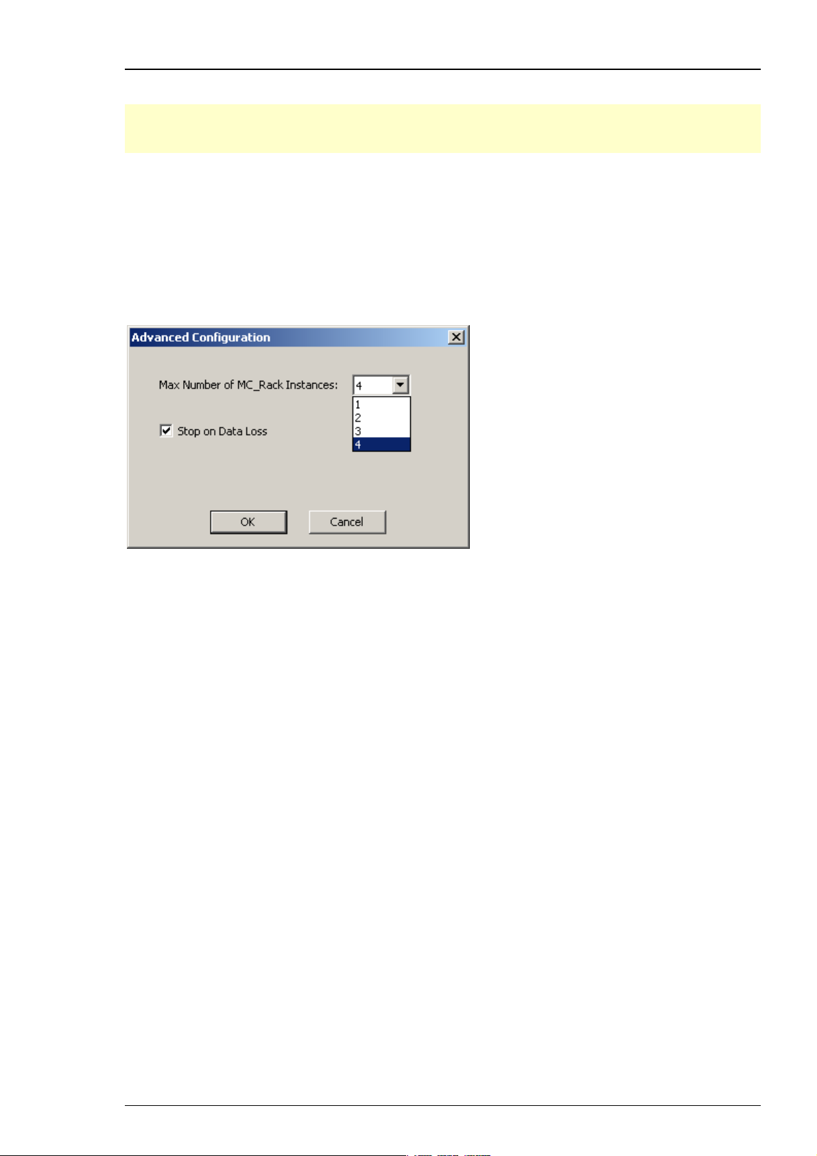
3.2.3 Advanced Configuration
Important: This feature can only be used when working with the USB based data acquisition
systems USB-ME256 and USB-ME128. If you use a MC_Card or an USB-ME-16/32-FAI, please do
not change the default setting of "Max. Number of MC_Rack Instances = 1".
On the Edit menu, click Advanced Configuration to select the maximum number of instances of
MC_Rack that can run simultaneously. These instances operate independently from each other.
This feature is meant to be used with the new USB based data acquisition systems USB-ME256
and USB-ME128. When two or four amplifiers are connected to the data acquisition, it is possible
to operate each amplifier independently with one instance of MC_Rack. It is also possible to
operate 128 or 256 channels with one instance of MC_Rack, for example, when working with an
USB-MEA256 amplifier and a MEA with 256 electrodes. See Data Source Setup for details on the
configuration. Up to four instances of MC_Rack can be started in parallel.
If the option "Stop on Data Loss" is selected, the MC_Rack program stops recording
if it encounters problems during recording of a file. An error message will be displayed
in the status bar.
24
Page 31

Step by Step Tutorial
Operating 256 channels with USB-ME256 device with one instance of MC_Rack
Using an USB-ME256 device, it is possible to operate 256 channels with one instance of MC_Rack.
1. Connect an USB-ME256 device to the data acquisition computer. Start MC_Rack software program.
2. Click Edit: Advanced Configuration and keep the default setting: Max. Number of MC_Rack
Instances = 1.
3. Click Edit: Data Source Setup and select USB MEA under Data Source.
4. Virtual Device Configuration: Click 1 x 256 from the drop down list on the left. In Virtual Device
Configuration drop down list on the right Block 1 (Channel 1...256) is displayed.
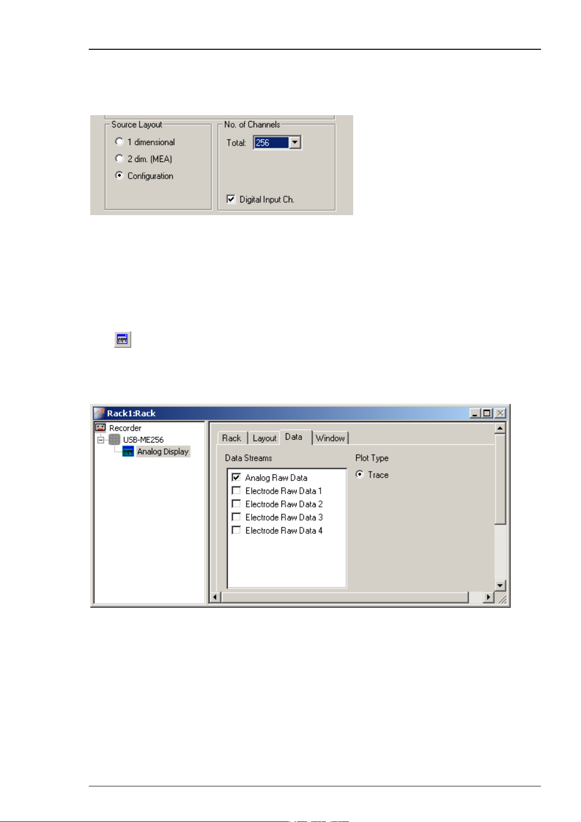
5. Source Layout: Choose Configuration in Source Layout and the total number of 256 from the drop
down list in No. of Channels.
6. Configure the connected amplifiers and MEA layouts independently from each other from the
available drop down menus.
The same proceeding is possible with USB-ME128 device. The total number of channel is reduced
to 128 channels, respectively.
Important: If working with one instance of MC_Rack, data acquisition from all four amplifiers
can only be started in parallel, and all data will be saved in the same file.
25
Page 32
MC_Rack Manual
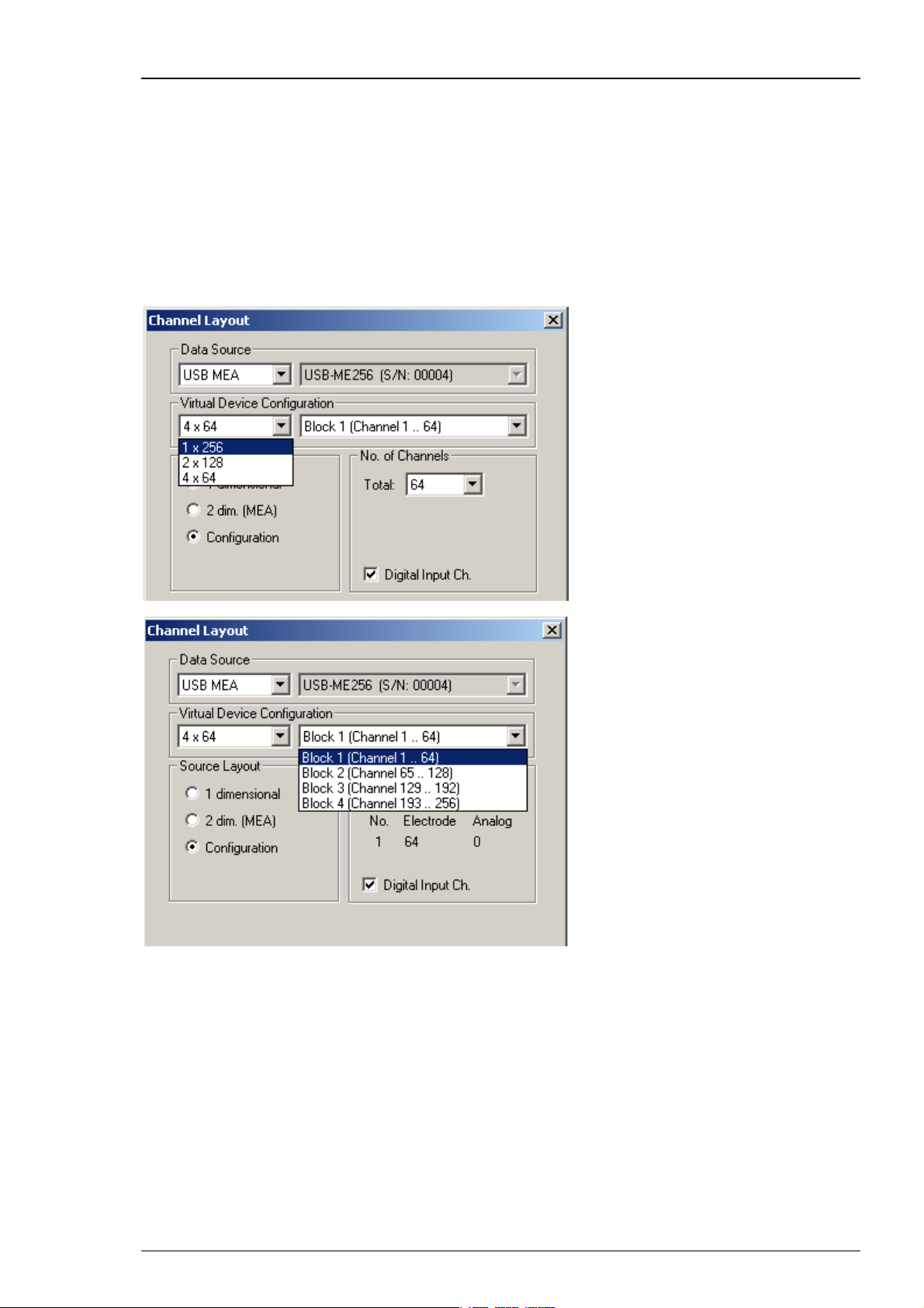
Operating 256 channels with USB-ME256 device with four instances of MC_Rack
Using an USB-ME256 or an USB-ME128 device, it is possible to operate 128 or 256 channels
with two or four instances of MC_Rack.
Click Advanced Configuration to select the number of instances of MC_Rack that you want
to run simultaneously. Please see screen shot above.
Example: Operating an USB-ME256 device with four amplifiers and with four instances
of MC_Rack.
1. Connect an USB-ME256 device to the data acquisition computer. Start the first instance of
MC_Rack. Click Edit: Advanced Configuration and define Max. Number of MC_Rack Instances = 4.
2. Click Edit: Data Source Setup and select USB MEA under Data Source. Choose 4 x 64 channels
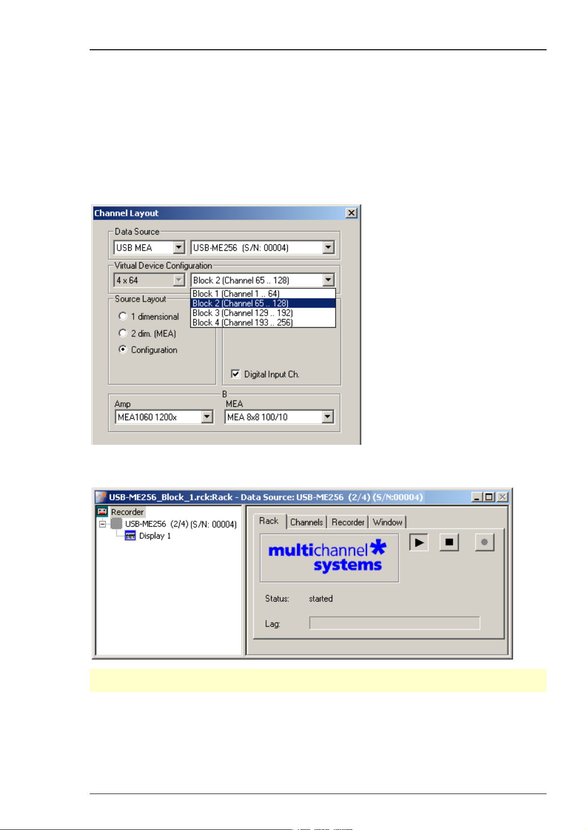
from the left drop down menu in Virtual Device Configuration, and Block 1 (Channel 1...64)
from the right drop down menu. Block 1 corresponds with input A of the USB-ME256.
3. Configure the correct amplifier type and electrode layout for input A
4. Open the second instance of MC_Rack software program.
5. Click Edit: Data Source Setup and select Block 2 (Channel 65...128) from the right drop down
menu. Block 2 corresponds with input B of the USB-ME256.
6. Configure the correct amplifier type and electrode layout for input B.
26
Page 33

Step by Step Tutorial
7. Open the third instance of MC_Rack software program.
8. Click Edit: Data Source Setup and select Block 3 (Channel 129...192) from the right drop down
menu. Block 3 corresponds with input C of the USB-ME256.
9. Configure the correct amplifier type and electrode layout for input C.
10. Open the fourth instance of MC_Rack software program.
11. Click Edit: Data Source Setup and select Block 4 (Channel 193...256) from the right drop down
menu. Block 4 corresponds with input D of the USB-ME256.
12. Configure the correct amplifier type and electrode layout for input D.
13. If you try to open a fifth instance of MC_Rack an error message will be displayed. Please see
Troubleshooting.
Now you are able to operate the different blocks of 4 x 64 channels with independent MC_Rack
instances, and with independent configured amplifiers and MEA layouts.
The same proceeding is possible with USB-ME128 device. The total number of channel is reduced
to 128 channels and two blocks and inputs (A and B), respectively.
The Reuse of an existing Rack File with multiple Instances of MC_Rack
The reuse of an existing rack file with multiple instances of MC_Rack running on the same
computer is explained, using the example of the USB-ME256-System. If you are working with
an MEA2100-32-System, please operate in the same principle.
27
Page 34
MC_Rack Manual
Opening an existing Rack File with USB-ME256 and multiple Instances of MC_Rack
If you build up (and saved) a complicated rack in the first instance of MC_Rack which you want
to reuse in the second instance of MC_Rack, please do the following:
1. Start the second instance of MC_Rack.
2. Click "Open" in File menu. The dialog "Open Rack Files" appears. Select the desired rack file.
3. Before the selected file will open in the second instance of MC_Rack, you have to change the
data source specification from the copied file. That is why the dialog " Channel Layout" in
"Data Source Setup" will automatically appear again. Please choose the appropriate MEA
amplifier via block number, assigned the second instance of MC_Rack.
4. Now the reused rack file will be opened in the second instance of MC_Rack. The data source
used for the rack is shown in the blue header of the dialog and after the data source icon.
Note: Please do not miss one of the described steps when reusing an existing file! Otherwise
you have to delete the rack and start the instance of MC_Rack again.
Repeat step 1 to 4 to open the third and fourth instance of MC_Rack with an existing file
to control the amplifiers three and four.
28
Page 35
Step by Step Tutorial
Operating two MEA2100-32-Systems with multiple instances of MC_Rack
Using a MEA2100-32-Systems with two MEAs or two headstages with two MEAs, it is possible
to operate up to four devices with up to four instances of MC_Rack, running on a single data
acquisition computer.
Click “Advanced Configuration” to select the number of instances of MC_Rack that you want
to run simultaneously. Please see screen shot above.
Important: It is not possible to connect one device with more than one instance of MC_Rack.
1. Start the first instance of MC_Rack.
2. Click Data Source Setup on the Edit menu. Select USB on the left drop down menu of the "Data
Source", and MEA2100-32 on the right drop down menu. Please see chapter "Defining the Data
Source". Select the block you want to control with the first instance of MC_Rack "Block" number.
3. Select Configuration in Source Layout. The total number of channels is 32 with an additional
digital input channel or not.
4. Add MEA2100-32 (S/N 00018-A, headstage A), for example, as the data source to your virtual
rack for the first instance of MC_Rack. The data source and its serial number are displayed
in the blue header of the dialog of the "Rack" tab as well as on the left side of the display.
29
Page 36

MC_Rack Manual
5. Start the second instance of MC_Rack.
6. Click "Data Source Setup" in Edit menu. Select the headstage you want to control with the second
instance of MC_Rack via serial number, for example MEA2100-32 (S/N:00018-B). Add the desired
data source. The data source and its serial number are displayed in the blue header of the dialog
of the "Rack" tab (second instance) as well as after the data source icon.
Opening an existing Rack File with MEA2100-32-System and multiple instances
of MC_Rack
If you build up (and saved) a complicated rack in the first instance of MC_Rack which you want
to reuse in the second instance of MC_Rack, please do the following: Start the second instance
of MC_Rack.
1. Click "Open" in File menu. The dialog "Open Rack Files" appears. Select the desired rack file.
2. Before the selected file will open in the second instance of MC_Rack, you have to change the
data source device specification from the copied file. That is why the dialog " Channel Layout"
in "Data Source Setup" will automatically appear again.
3. Please choose the appropriate MEA2100-32 headstage via block number, assigned the second
instance of MC_Rack.
4. Now the reused rack file will be opened in the second instance of MC_Rack. The data source
used for the rack is shown in the header and after the data source icon.
Note: Please do not miss one of the described steps when reusing an existing file!
Otherwise you have to delete the rack and start the instance of MC_Rack again.
Maximal Sampling Frequency
Usually, the maximal sampling frequency for MCS data acquisition systems is 50 kHz. However,
when using some advanced features of the USB-ME256 and USB-ME128, some limitations apply.
The maximal sampling frequency that can be achieved with 256 channels is 40 kHz. This is possible
when using the USB-ME256 with the "Virtual Device Configuration" 1 x 256 (Please see above).
With the USB-ME128 and USB-ME256 it is also possible to split the data stream into 2 x 64 or
2 x 128 and 4 x 64 channels, respectively, again by using the "Virtual Device Configuration".
These virtual machines can then be controlled independently by up to four instances of MC_Rack.
However, splitting the data stream into several virtual devices consumes system performance.
Therefore, the maximal sampling frequency is limited to 25 kHz when using the virtual device
configuration 2 x 64 (USB-ME128) or 2 x 128 and 4 x 64 channels (USB-ME256).
The Additional Analog Channels A1 to A4
The devices USB-ME256, USB-ME128, USB-ME64 and USB-MEA256 are equipped with four
additional analog channels A1 to A4. Please refer to the respective manuals.
The additional analog channels A1, A2, A3 and A4 are available in MC_Rack data display
and in MC_Rack long term display.
Note: Because of the different scaling of electrode data channels and the additional analog
channels, it is recommended to visualize the analog channels in a separate display.
30
Page 37
Step by Step Tutorial
Availability of Additional Analog Channels in USB-ME256 (and USB-ME128 respectively)
Depending on the selected "Source Layout", it is possible that no, or not all additional analog
channels are available. To have full access to the analog channels, please use the "Configuration"
option of the data source setup. If other data source layouts are selected, limitations apply:
Source Layout 1 dimensional: No additional analog channels are available.
Source Layout 2 dim. (MEA): Three additional analog channels are available A1, A2, A3.
Source Layout Configuration: All four additional analog channels are available A1, A2, A3 and A4.
Visualizing the Additional Analog Channels
Click
to add a data display. On the left window pane of the dialog the data display appears,
labeled ”Display 1”. Double click on "Display 1" to rename the display for discrimination of the
analog and electrode displays.
In the "Data" tab, select "Analog Raw Data" only.
31
Page 38

MC_Rack Manual
In the "Layout" tab, select the "Default Map". The additional analog channels A1 to A4
are displayed. It is also possible to use a custom layout (for example 2x2 electrodes). Please
see chapter “Monitoring Activity” for more information about designing channel maps.
Additional Analog Channels with Different Instances of MC_Rack
If you use the Advanced Configuration to run more than one instance of MC_Rack at once,
the same four additional analog channels A1 to A4 can be displayed in any of these instances.
3.2.4 Adding a Data Source
In MC_Rack, the input data streams for the virtual rack can come from different data sources:
From the data acquisition board MC_Card or from the Replayer, that is, from previously
recorded data (*.mcd) files, or from USB based data acquisition systems like USB-ME256,
USB-MEA256, USB-ME16-FAI or MEA2100-System.
Here, we want to acquire new data and choose, for example the MC_Card as data source.
32
Page 39
Step by Step Tutorial
1. Click the electrode array symbol on the toolbar or click Add MC_Card on the Edit menu.
The program detects the MC_Card automatically. If you have no MC_Card installed on the
computer, the simulation mode is started automatically, and you will be informed by a message.
(If you have a MC_Card, but you still get an error message, the driver installation may be invalid.
Please contact your local retailer for support.)
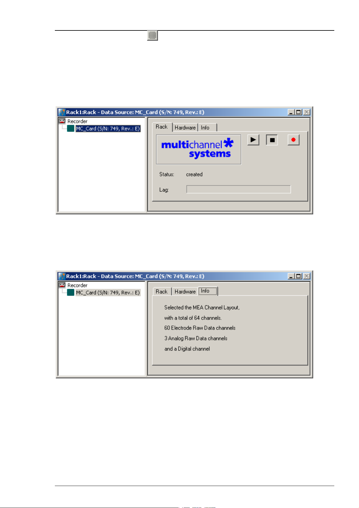
You see the MC_Card virtual instrument in your virtual rack. When you select the MC_Card so
that the name appears highlighted in blue, you see three tab pages on the right: The general
Rack tabbed page, and the MC_Card specific Hardware and Info tabbed page. In the Hardware
page, you can define the hardware related settings. The Info page shows the channel layout.
2. In the tree view pane of the virtual rack, select the MC_Card, click the Info tab, and check the
channel layout settings that you have defined in the last step. You cannot modify the settings
anymore once you have added the MC_Card. If the settings are not appropriate, remove the
MC_Card from the rack (by selecting the MC_Card In the tree view pane of the virtual rack
and pressing DELETE), and go back to the last step "Defining the Data Source".
The following screen shot shows the information on the standard layout for the MEA60-System.
33
Page 40
MC_Rack Manual
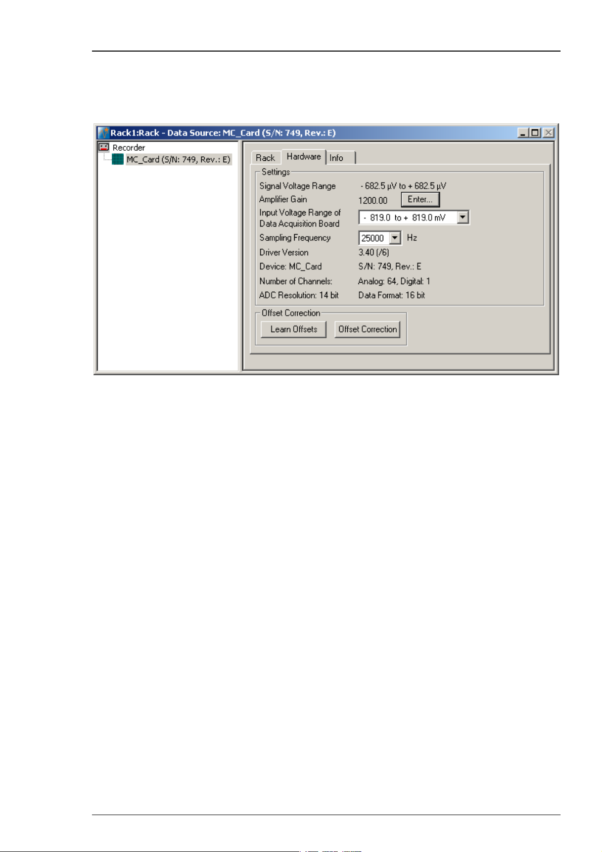
3. Click the Hardware tab. Here, you can define hardware related parameters. Please note that the
amplifier gain is an intrinsic property of the amplifier and cannot be altered, whereas the input
voltage range and the sampling rate of the data acquisition card can be adjusted to your
needs. On this page, you will also find hardware related information like the MC_Card driver
version and the serial number. Please keep this information at hand when contacting the support.
4. Click Enter to enter the Amplifier Gain settings according to your hardware. The gain settings
are used for scaling and displaying the signals properly. So if you specified a wrong gain, you
would perceive wrong signal amplitudes leading to false documentation and results. The default
settings are 1200 for the standard MEA1060 amplifier, and 1100 for the standard MEA1060-BC
amplifier. The amplifier gain of the MEA2100-System is automatically set, depending on the
version of the hardware. If you have a ME-System, you should enter the total gain of the
amplifiers. For example, if you have a MPA8I (with a gain of 10) and a filter amplifier with
a gain of 100, you have a total gain of 1000. Please check the technical specifications of the
connected amplifier(s) and make sure that you enter an appropriate value.
5. Select an Input Voltage Range of Data Acquisition Board for the MC_Card from the drop-
down list. For standard signals and a standard gain amplifier, the default input range of -819
to +819 will be fine. You need a higher input voltage range if your biological sample generates
higher voltages, for example, cardiac signals from whole-heart preparations, and/or the amplifier
gain is considerably higher. The lower the input voltage range, the higher is the voltage
resolution. Please see also Defining MC_Card Settings in the MC_Rack Features section.
6. The Signal Voltage Range is calculated from the Input Voltage Range of the Data Acquisition
Board divided through the Amplifier Gain Factor.
7. Select a Sampling Rate from the drop down list. For most applications, 25 kHz will be fine.
Please see also Defining MC_Card Settings in the MC_Rack Features section.
8. An Offset Correction is generally not necessary. You may use it when you observe a disturbing
voltage offset on the input channels. Or you may use it during testing the system with a test
model probe. Make sure that there are no signals on the channels when using the offset
correction. Click Offset Correction to activate the Offset Correction. Click Learn Offsets to
perform an individual offset correction for each input channel. MC_Rack takes 100 ms of the
recorded data in the moment when the button is pressed to calculate the DC offset. The mean of
this 100 ms sweep is subtracted from the recorded data as long as the Offset Correction button
is pressed. The individual offset values for each channel are saved in the local settings of the data
acquisition computer and are only overwritten when you click Learn Offsets again. Make sure
you press the Learn Offsets button only when you have no real input signals or irregular noise
signals on the electrodes. To be on the safe side, connect a test model probe to the amplifier.
34
Page 41
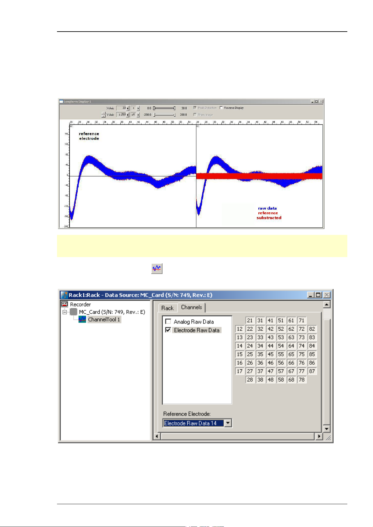
3.2.5 Channel Tool
The Channel Tool feature in MC_Rack allows the selection of one MEA electrode as reference
electrode. The tool works similar to the offset correction and influences the signal to noise ratio.
If there are problems with homogenous noise on all electrodes, the user is able to select one
electrode without signal as reference. The voltage value of this reference electrode will be
mathematically subtracted sample point per sample point from all electrode signals in the
stream. For example, a low frequency noise on all electrodes will be eliminated this way.
Step by Step Tutorial
Note: Be careful to choose an electrode with noise only as reference electrode. If the reference
electrode contains signals too, the value of the signals will be subtracted together with the noise
value, and falsify the data.
Click the "Channel Tool" icon
from the Edit menu. The following dialog appears. Click the "Channels" tab.
in the main window toolbar, or select "Channel Tool"
Select the data stream you want to apply the channel tool: Electrode Raw Data in this example.
Select a "Reference electrode" from the "Reference electrode" drop down menu.
35
Page 42

MC_Rack Manual
3.2.6 Monitoring Activity Continuously
Next, you need a Data Display for monitoring the ongoing activity continuously.
Click
to your virtual rack. The Data Display displays the channels in the layout of the Channel Map
you have created or loaded. Channel maps are saved as *.cmp files. The default channel map at
first program startup is the 8x8 grid of standard MEAs (saved as 8x8mea.cmp). When you have
changed the channel map, the last used channel map is loaded automatically as the default.
For monitoring the ongoing activity continuously over a longer period, add the Longterm
Display.
on the toolbar or click Add Data Display on the Edit menu to add a Data Display
Click
Display to your virtual rack.
The Longterm Display shows analog raw data and electrode raw data. You can display data
in a user defined time span from 1 second up to 60 minutes. The longterm display tool allows to
observe the development of the signals over a longer period. The Longterm Display displays
the channels in the layout of the Channel Map you have created or loaded. In the Longterm
Display the adjustment of the x-axis is disabled, and you cannot zoom in. The peak detection
is permanent selected (for more information please see chapter Peak Detection).
on the toolbar or click Add Longterm Display on the Edit menu to add a Longterm
36
Page 43
Step by Step Tutorial
Defining the display layout
Note: You can set up any channel layout that meets your requirements and save it for later use.
You can pick preconfigured channel maps for all MEAs available from Multi Channel Systems
from the MCS Channel Maps drop down list.
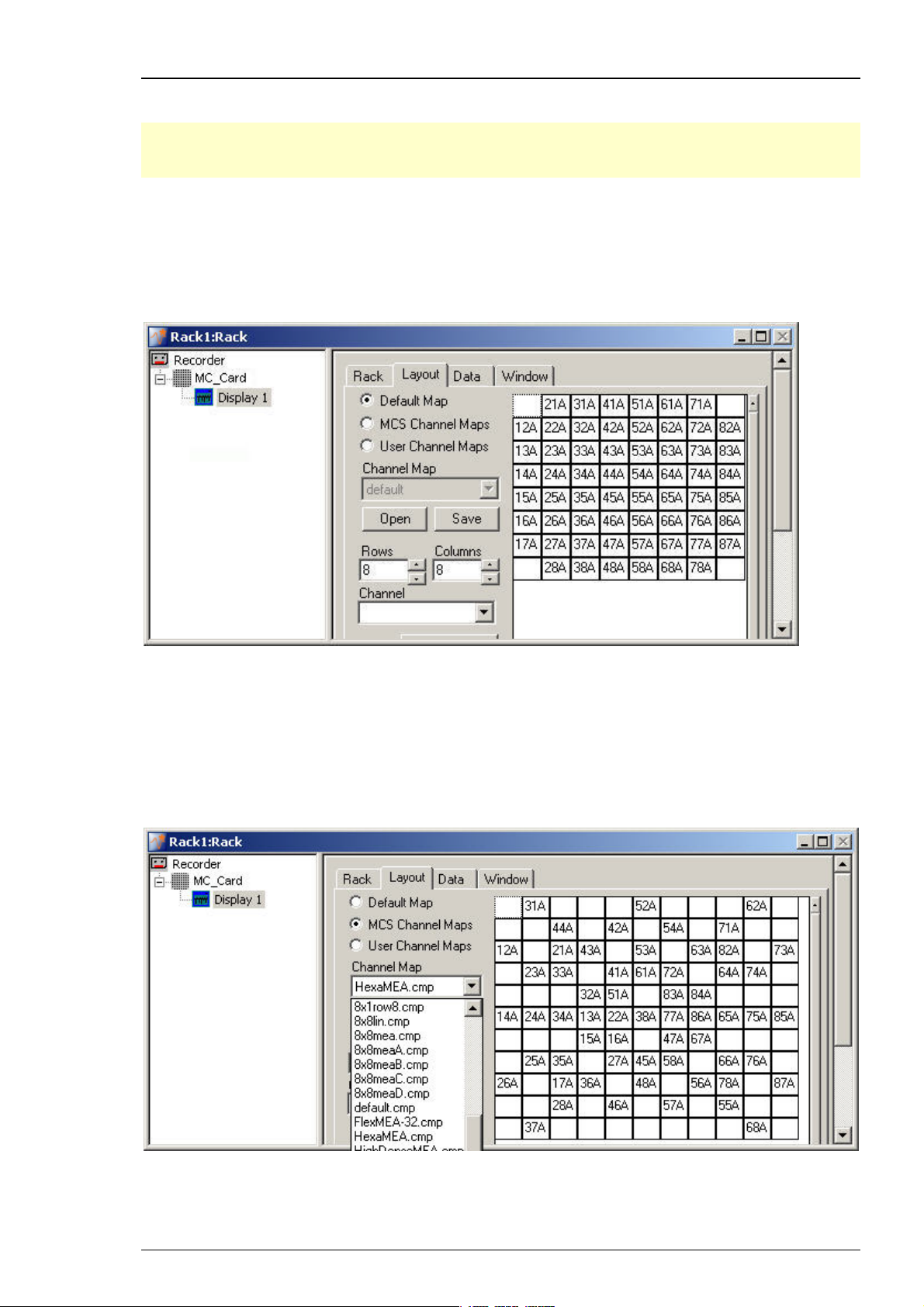
1. In the tree view pane of the virtual rack, select the Display 1 and click the Layout tab.
You see the currently used display layout of the Default Map: The standard 8x8 grid. The
electrodes are labeled in relationship to their position in the electrode grid, respectively to their
coordinates. The first number refers to the x-axis (column), the second number refers to the y-axis
(row). The character refers to the MEA, MEA A in this case, that is important when using more
than one MEA amplifier.
.
2. To load a different Channel Map, click MCS Channel Maps or if the channel map is user
defined, click User Channel Maps. You can use the Channel Map drop down menu or you
browse your folders and open the MC_Rack program folder. In the Channel Maps folder,
you will find a selection of standard layouts, for example, for different MEA types, layouts for
the MEA120-System (8x8meaA.cmp and 8x8meaB.cmp for the two separate MEA amplifiers), and
various other layouts for single electrode columns on a MEA, for example. Select an appropriate
channel map and click Open. The MEA layout appears on he right side of the dialog box and the
display shows the channels in the selected layout accordingly.
.
3. For setting up a custom layout, enter the desired number of rows and columns.
The layout grid displayed on the right is updated accordingly.
37
Page 44

MC_Rack Manual
4. Click any electrode number that you want to change and select the desired channel number
from the Channel list, or type the channel number with the keyboard.
5. If you want to keep the custom layout for later use, click Save and enter a file name.
Option: Advanced
Hint: For advanced users only! Adjusting a custom MEA layout to a custom data display layout.
Click button Advanced.
38
Page 45

Step by Step Tutorial
Additional windows appear: Channel Offset, X- and Y- Offset and X- and Y-Extend.
These commands concern the data display layout only.
Example: Setting up a MEA layout 5 x 5 with electrodes in different sizes.
39
Page 46

MC_Rack Manual
Customized Display
1. Click User Defined Map.
2. Set up a MEA layout with a 5 x 5 grid using Rows and Columns. The MEA layout appears
on the right side of the dialog box and in the data display.
3. Click into the empty squares of the electrode grid and select the desired channel numbers
from the Channel drop down menu. The data display shows the channels in the selected
layout accordingly.
4. The electrode referring to channel No.13 (in the middle of the first row) is bigger than the other
electrodes. Click 13 in the electrode grid. Enlarge the electrode in the data display with X-Extend
= 300 and Y-Extend = 200 by overwriting the 0 in the numeric updown box or clicking the arrow
buttons.
5. To change the position of the electrode in the data display use X-Offset for moving it to the
left (negative integer) and to the right (positive integer), and Y-Offset for moving it downward
(positive integer) and upward (negative integer). The X- and Y-Offset has a range from -100 to
+100. Overwrite the 0 in the numeric updown box or click the arrow buttons. The layout displayed
on the data display is updated immediately.
6. The electrode referring to channel No. 23 is bigger as well. Do the same procedure to enlarge
and move it as described in point 4 and 5. Repeat this procedure as often as necessary, and you
are able to build your custom display layout.
If you have two amplifiers in your setup (MEA120 System), use Channel Offset to assign the
custom layout to the correct data stream. Please read also next chapter Selecting data streams.
Until today, it only makes sense to give 0 in Channel Offset for connecting the custom layout
to Electrode Raw Data 1 or 64 for connecting the custom layout to Electrode Raw Data 2.
If you want to keep the custom layout for later use, click Save and enter a file name.
40
Page 47

Step by Step Tutorial
Selecting data streams
1. Click the Data tabbed page.
In this page, you select the data streams that you want to monitor in the display. The Electrode
Raw Data stream is already preselected. You can select the Analog Raw Data stream if you have
connected a data source to an analog data input (A1 A2 and A3 for the MEA-System). It may make
more sense to display the additional analog channels in a separate display, though, because in
most cases, the scale of the axes will not be appropriate for both the electrode data stream and
the additional analog data stream. For monitoring the digital data stream, please use the Digital
Display. The Data Display has an oscilloscope-like function. Therefore, only the Trace option
is available. The Parameter Display for graphing extracted parameters provides more options.
Starting MC_Rack
Click Start
(either on the Measurement menu, the toolbar, or the Rack tabbed page) to
start the data acquisition. Each virtual instrument in the rack starts to process the channels and
data streams that were assigned to it, that is, the Trigger Detector detects events on the digital
input channel and generates a trigger data stream that, in turn, triggers the display. The display
is refreshed at each trigger event.
Refresh rate and ranges
1. Switch to the Display 1 window.
2. You can zoom in the signals by choosing the appropriate range of the y-axis from the Y-Axis
drop-down list, or by clicking the arrow buttons.
3. You can select the display refresh rate and maximum x-axis range from the X-Axis drop-down
list.
4. You can fine-tune the ranges of the y- and x-axis with the sliders.
41
Page 48
MC_Rack Manual
3.2.7 Recording Data
MC_Rack's philosophy is to strictly separate the actions of all virtual instruments in a rack. That
means, that you could record to hard disk completely different data streams and channels than
you monitor on the screen. This has the advantage that you can store exactly the channels you
are interested in, but it also has the slight disadvantage that all virtual instruments have to be
set up separately. Please be especially careful when configuring the Recorder to avoid data loss.
Selecting data streams and channels for recording
The fate of each single channel is independent from other channels. You can pick exactly the
channels you like to save from all generated data streams. For example, you can decide to save
only one channel of raw data, but the peak-to-peak amplitude results of all, or of a specific
selection of channels.
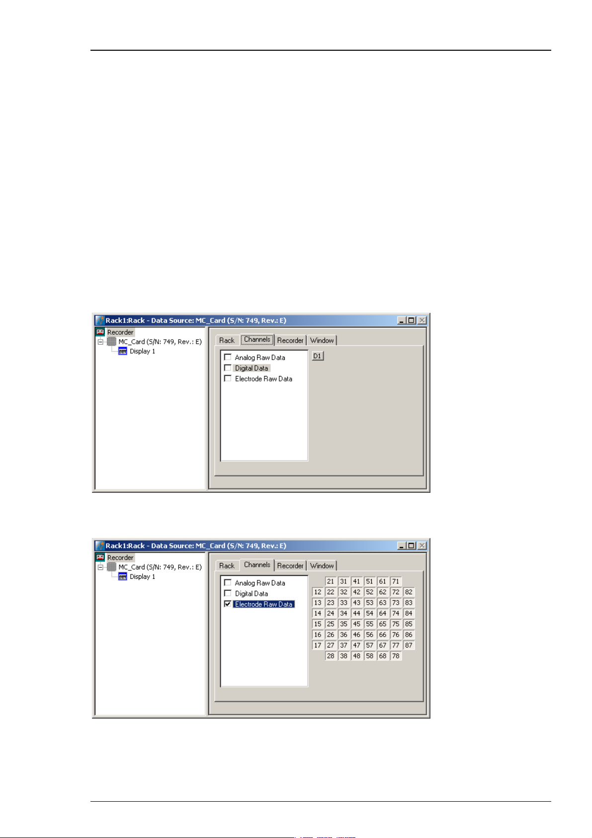
Select the Recorder in the virtual rack tree view pane and then click the Channels tabbed page.
On the white pane on the left of the Channels page, you see the data streams that are available
with your data source settings, for example, the Analog Raw Data, Digital Data, and Electrode
Raw Data streams for the MEA-System. (It does not matter whether you have really connected
a device to the inputs, though.) If you have selected a channel layout without the digital input,
the Digital Data stream will not be available, for example.
1. Click the data stream that you are interested in, that is generally the Electrode Raw Data
stream. The available electrode channels appear in a button array on the right side.
2. You can now either select all channels by clicking the check box next to the Electrode Raw Data
stream name, or you can pick single channels by clicking the corresponding buttons. For more
information, please see "Channel Selection" in the MC_Rack Features section. Only data from
the selected channels will be saved to the hard disk.
42
Page 49
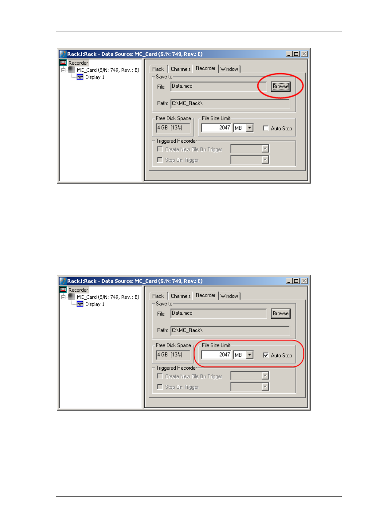
Choosing the file name and path
1. Click the Recorder tab.
Step by Step Tutorial
2. Browse your folders and select a path.
3. Type a file name into the text box.
4. Confirm by clicking Save.
The file extension for the data files is *.mcd.
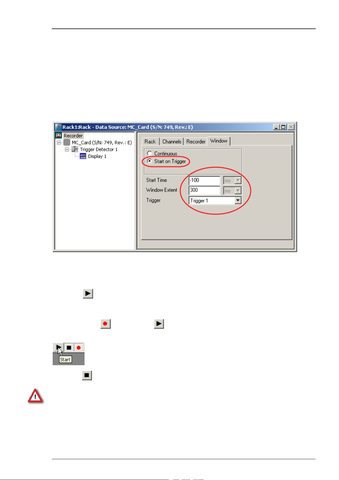
File size limit
The file size is not limited by default, but the user can limit it. When the maximum file size
specified by the user has been reached, a new file is generated automatically. The file name
is extended by four digits, counting up, for example, LTP-Parameters0001.mcd,
LTP-Parameters0002.mcd, and so on.
If you rather prefer that the recording is completely stopped when a file has reached the
maximum size, please select the option Auto Stop. For information on more options,
please see "Generating Data Files" in the MC_Rack Features section.
43
Page 50
MC_Rack Manual
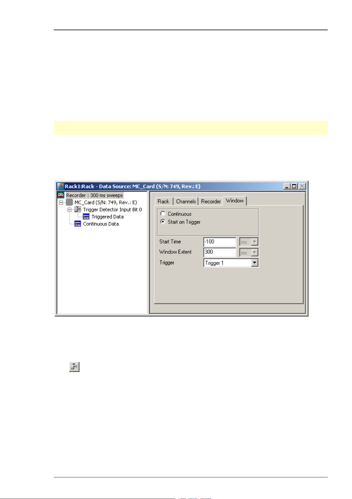
Continuous recording versus triggered recording
For recording evoked activity, like LTP experiments or retina recordings, it does generally not
make much sense to record continuously. It is recommended to record only the signals of interest
following a trigger event, for example, a TTL signal from the stimulator, to save disk space.
You can then define the Start Time (before the trigger event) and the Window Extent (total
cutout length). Please do not prolong the "Window Extent" time interval to more than 3800 ms.
Please read chapter "Triggering MC_Rack on the Stimulus" for more information about "Window
Extent" settings. For more information on continuous and triggered data, please see the chapter
Continuous and Triggered Data in the "Step by Step Tutorial" section.
This option is only available if there is a trigger stream available, that is, a Trigger Detector
in the rack.
3.2.8 Starting Data Acquisition and Recording
Now that you have completed the virtual rack, you are ready to start the rack.
Click Start
to start the data acquisition. Each virtual instrument in your rack starts to process the channels
and data streams that were assigned to it.
Click first Record
electrodes selected in the Recorder is saved to the file and location specified in the Recorder.
Click Stop
Warning: Only data of the channels and data streams that were selected in the Recorder
are saved in your data file when you start a recording. Data is only saved to the hard disk when
the red Record button is pressed in. Make always sure that you have selected all channels of
interest, and that the Record button is active before starting an experiment to avoid data loss.
(either on the Measurement menu, the toolbar, or the Rack tabbed page)
and then Start to write data to the hard disk. The data from the
to stop the data acquisition.
44
Page 51
3.3 Monitoring and Recording Triggered Activity
3.3.1 Triggering MC_Rack on the Stimulus
When recording evoked responses, such as in a LTP or PPF experiment, you usually want to
synchronize the data displays and the recording to the electrical stimulation. For this purpose,
you can feed in TTL pulses to the digital input bits of the digital input channel. In the standard
configuration, three BNC sockets are available for applying up to three separate trigger pulses.
You can upgrade the system with a digital IN / OUT expansion that supports all 16 digital input
(and output) bits that are provided by the MC_Card. For more information, see the ME- or MEASystem manual.
Note: It is recommended to use the digital input port for feeding in TTL signals.
The analog inputs are intended for analog signals, like patch clamp data, for example.
For triggering MC_Rack, we need to set up a Trigger Detector in the virtual rack. The trigger
stream generated by the Trigger Detector can then be used for triggering Data Displays,
Analyzers, and the Recorder.
See also the sample rack Display_Triggered.rck.
Step by Step Tutorial
1. Configure your stimulator to output a TTL pulse that is synchronized to the stimulus pattern.
If you are using a Stimulus Generator (STG) from MCS, you can program a Sync Out channel.
2. Connect the TTL output to digital input bit 0 (the first BNC socket). If you are using a MEA-System,
make sure not to confuse the digital inputs with the analog inputs.
3. Click
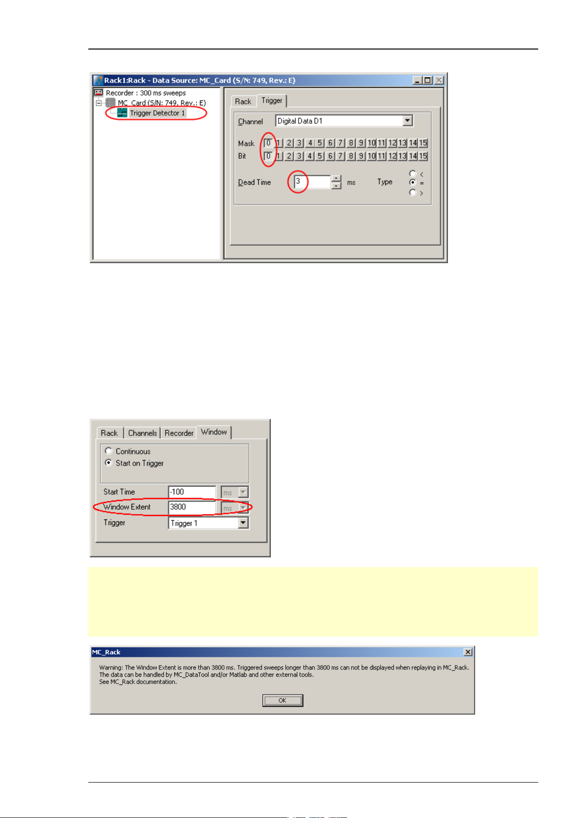
4. In the tree view pane of the virtual rack, select the Trigger Detector, and click the Trigger page.
on the MC_Rack toolbar to add a Trigger Detector to the virtual rack.
45
Page 52
MC_Rack Manual
From the Channel list, select the Digital Data D1 channel.
A button array appears, one button for each digital input bit. With the Bit button, the logical
state (generally HIGH) that generates a trigger event is selected. With the Mask buttons, you
can select the bits that you want to use; all unused bits are masked.
The digital input bit 0 is already preselected. The logical state that generates a trigger event is
set to HIGH. This is fine and you do not need to change it. (If you had, for example, connected the
TTL output to digital input bit 1, you would need to select 1 instead of 0, and mask all other bits.)
You may want to change the dead time (the time after a trigger event where no following trigger
event is accepted), for example, if you run a paired pulse protocol, and want to trigger MC_Rack
only on the first stimulus pulse.
Click Recorder and select "Window" tab.
Important: The "Window Extent" is the total time of the cutout sweep. If you prolong the
trigger in “Window Extent” to more than 3800 m, a Warning will pop up. MC_Rack will record
data, but you cannot display these data when replaying them, because the MC_Rack display
setting for displaying sweeps is maximal 3800 ms. Please record the sweeps in MC_Rack, but
export the data with MC_DataTool to custom ASCII import programs, for example to Matlab,
for further analysis.
After recording long sweeps with "Window Extent" settings near to 3800 ms, and replaying
the respective *.mcd file with the MC_Rack Replayer, please slow down the "Replay Speed"
in the "Replayer" tab. Otherwise MC_Rack might have problems with displaying the data.
46
Page 53

3.3.2 Monitoring Triggered Activity
Next, you need a Data Display for monitoring the ongoing activity.
Step by Step Tutorial
Click
in series with the Trigger Detector to the virtual rack. (If you would put both instruments in
parallel, you would not be able to use the trigger stream generated by the Trigger Detector
for triggering the Data Display, because virtual instruments can only use the output streams
of other virtual instruments that are upstream in the virtual rack tree.)
The Data Display displays the channels in the layout of the Channel Map you have created
or loaded. Channel maps are saved as “*.cmp” files. The default channel map at first program
startup is the 8x8 grid of standard MEAs (saved as 8x8mea.cmp). When you have changed the
channel map, the last used channel map is loaded automatically as the default.
on the toolbar or click Add Data Display on the Edit menu to add a Data Display
1. Define the display layout and select the data stream as explained before.
Triggering the display
To graph the sweeps synchronized to the stimulation, you need to start the display on the trigger
event generated by the Trigger Detector that we set up earlier.
1. In the tree view pane of the virtual rack, select the Display 1, and click the Window tab.
2. Select the option Start on Trigger.
In the Trigger selection box, Trigger 1 appears automatically. It is the only trigger data stream
available in this rack. (You could set up multiple Trigger Detectors and trigger multiple displays
on separate trigger events.)
Starting MC_Rack
Click Start
start the data acquisition. Each virtual instrument in the rack starts to process the channels and
data streams that were assigned to it, that is, the Trigger Detector detects events on the digital
input channel and generates a trigger data stream that, in turn, triggers the display. The display
is refreshed at each trigger event.
(either on the Measurement menu, the toolbar, or the Rack tabbed page) to
47
Page 54
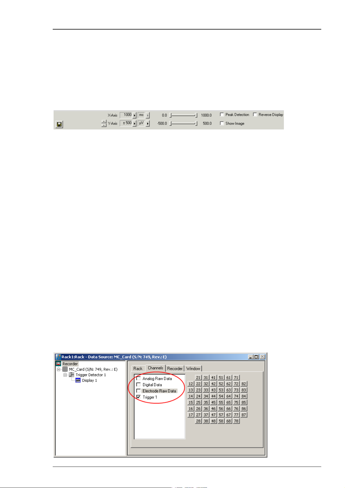
MC_Rack Manual
Adjusting the ranges
1. Switch to the Display 1 window.
2. You can zoom in the signals by choosing the appropriate range of the y-axis from the Y-Axis
drop-down list, or by clicking the arrow buttons.
3. You can select the maximum display refresh rate and maximum x-axis range from the X-Axis
drop-down list.
4. You can fine-tune the ranges of the y- and x-axis with the sliders.
3.3.3 Recording Triggered Data
MC_Rack's philosophy is to strictly separate the actions of all virtual instruments in a rack. That
means, that you could record to hard disk completely different data streams and channels than
you monitor on the screen. This has the advantage that you can store exactly the channels you
are interested in, but it also has the slight disadvantage that all virtual instruments have to be
set up separately. Please be especially careful when configuring the Recorder to avoid data loss.
In principle, you could record the evoked responses continuously, and trigger the displays and
analyzers when you replay the data. However, you would produce a huge amount of useless data,
as generally only the response following the stimulus is of interest. Therefore, it is recommended
to produce triggered data, that is, to cut out sweeps around the trigger event. This saves a lot
of disk space.
Selecting data streams and channels for recording
The fate of each single channel is independent from other channels. You can pick exactly the
channels you like to save from all generated data streams. For example, you can decide to save
only one channel of raw data, but the peak-to-peak amplitude results of all, or of a specific
selection of channels.
Select the Recorder in the virtual rack tree view pane and then click the Channels tabbed page.
On the white pane on the left of the Channels page, you see the data streams that are available
with your data source settings, for example, the Analog Raw Data, Digital Data, Electrode
Raw Data, and Trigger streams. (It does not matter whether you have really connected a device
to the inputs, though.)
Click the data stream that you are interested in, that is generally the Electrode Raw Data
stream, and the Trigger stream. The available electrode channels appear in a button array
on the right side.
48
Page 55
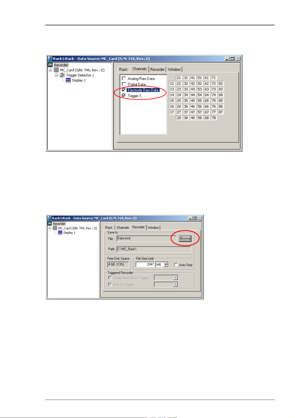
Step by Step Tutorial
1. You can now either select all channels by clicking the check box next to the Electrode Raw Data
stream name, or you can pick single channels by clicking the corresponding buttons. For more
information, please see "Channel Selection" in the MC_Rack Features section. Only data from
the selected channels will be saved to the hard disk.
Choosing the file name and path
1. Click the Recorder tab.
2. Browse your folders and select a path.
3. Type a file name into the text box.
4. Confirm by clicking Save.
The file extension for the data files is *.mcd.
File size limit
When the maximum file size specified by the user has been reached, a new file is generated
automatically. The file name is extended by four digits, counting up, for example
LTP-Parameters0001.mcd, LTP-Parameters0002.mcd, and so on.
If you rather prefer that the recording is completely stopped when a file has reached the
maximum size, please select the option Auto Stop.
For information on more options, please see "Generating Data Files" in the MC_Rack Features
section.
49
Page 56
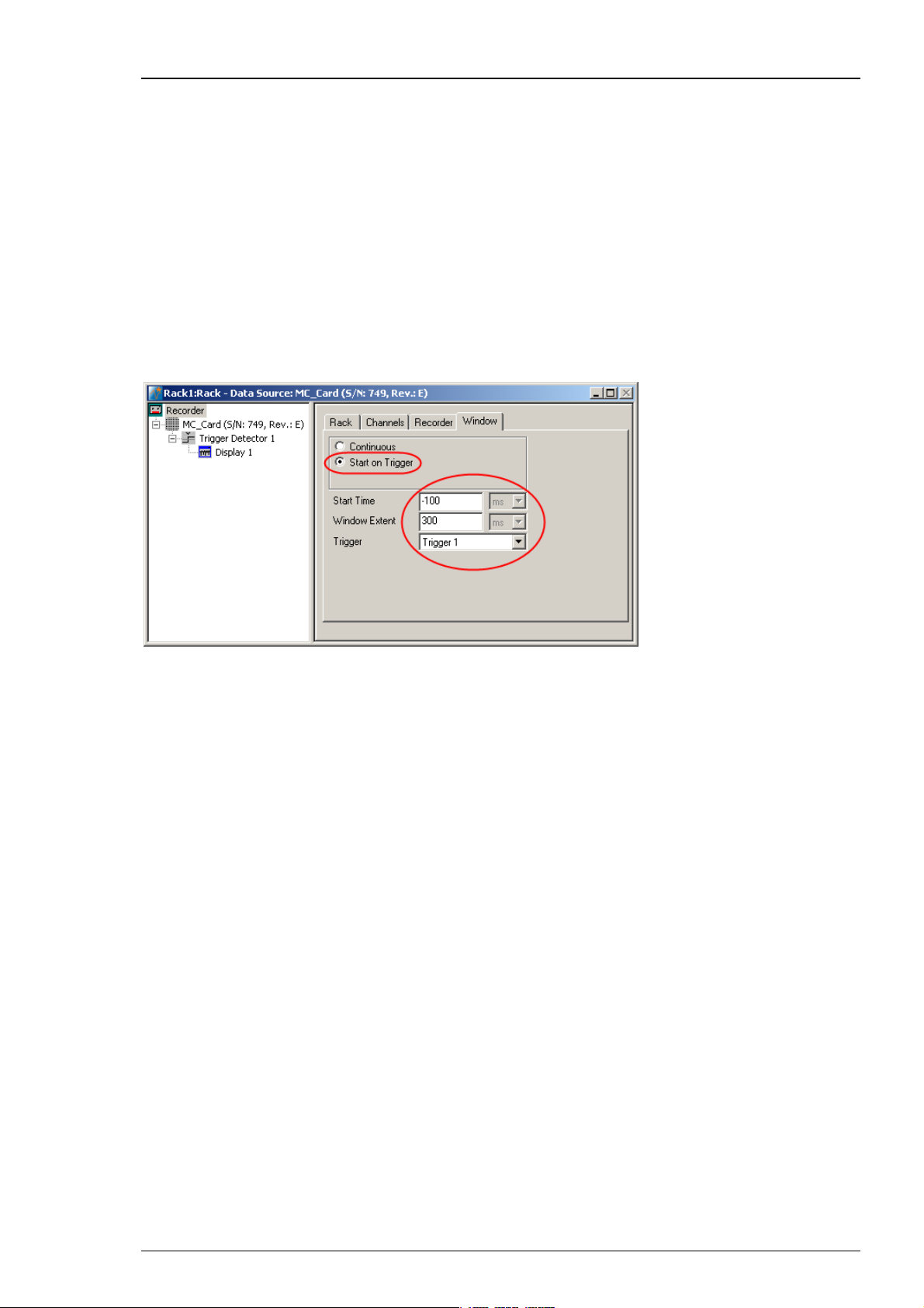
MC_Rack Manual
Triggering the recording
Again, the displayed data is independent from the recorded data. Thus we need to start
the recording on the trigger event generated by the Trigger Detector in the same manner
as we triggered the display.
This option is only available if there is a trigger stream available, that is, a Trigger Detector
in the rack.
1. In the tree view pane of the virtual rack, select the Recorder, and click the Window tab.
2. Select the option Start on Trigger. In the Trigger selection box, Trigger 1 appears
automatically. Two text boxes appear, too. These two parameters define the cutout: The Start
Time is generally a negative value, that is, the pretrigger time. The Window Extent is the total
time of the cutout sweep. Please read chapter "Triggering MC_Rack on a stimulus" for more
information about "Window Extent" settings.
50
Page 57
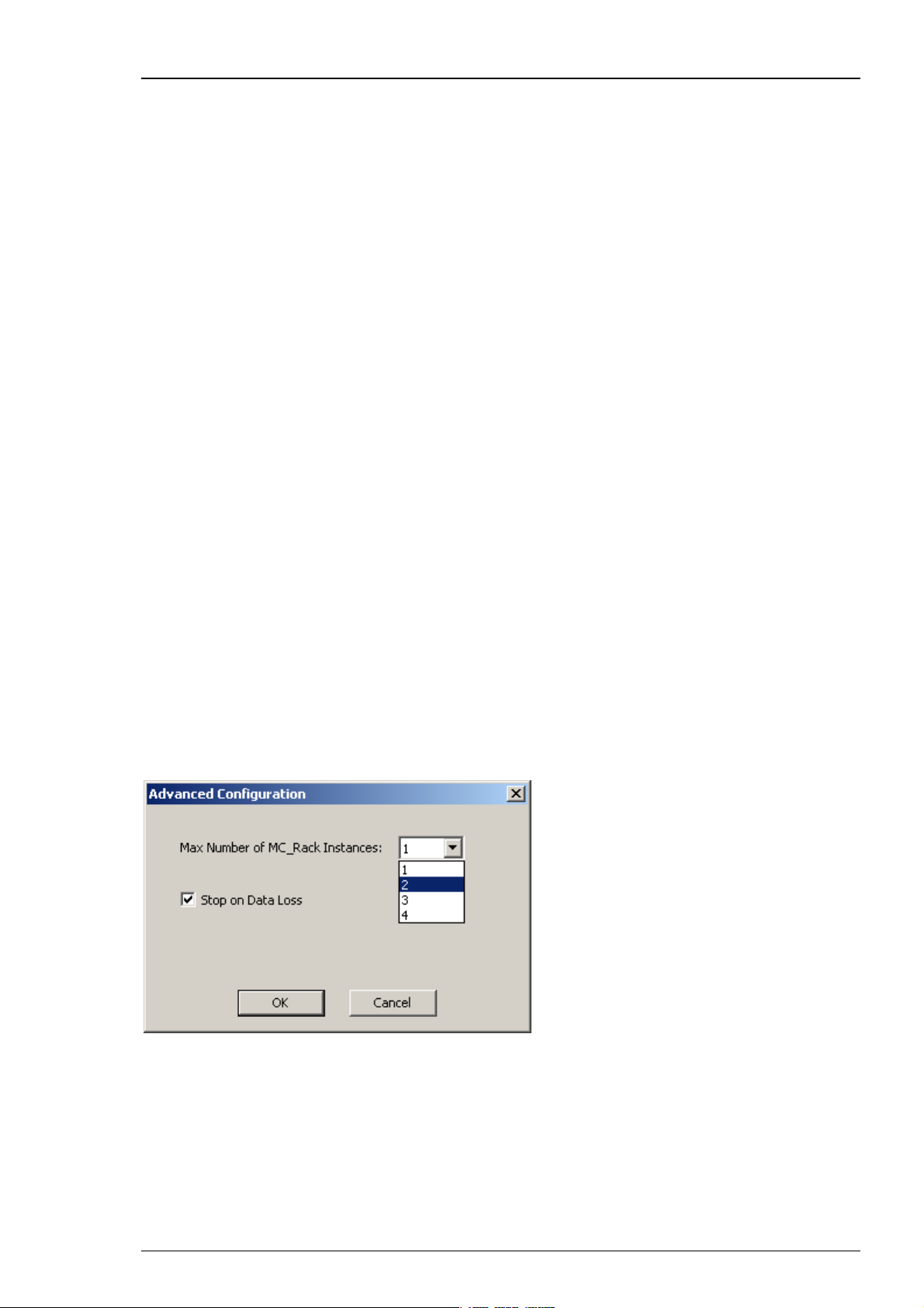
3.4 MEA2100-System
3.4.1 MEA2100-System
Specific Functions of the MEA2100-System
The following chapter summarizes all functions and settings of MC_Rack which are specific
for the MEA2100-System. You will find the identical information in several subchapters of
the MC_Rack manual and in the manual of the MEA2100-System.
MEA2100-System Configuration
The MEA2100-System is a flexible system, which can be used in different configurations.
Please read the MEA2100-System manual for detailed information. At the moment five types
of headstages are available for the MEA2100-System, which can be connected to the interface
board once or twice: A headstage for one MEA with 32 (MEA2100-HS32), 60 (MEA2100-HS60)
or 120 electrodes (MEA2100-HS120), and headstage for two MEAs with 32 (MEA2100-HS2x32)
or 60 electrodes each (MEA2100-HS2x60). One or two headstages can be connected to the
interface board (IFB) of the MEA2100-System.
MEA2100-32-System
Step by Step Tutorial
The MEA2100-32-System is a system providing all functions of a MEA2100-System, with the
exception of the real-time feedback via DSP. In “Data Source Setup” it is present as an own
device “MEA2100-32”. Please read the MEA2100-System manual for detailed information.
Using MC_Rack Software
Data Source Setup
Every MEA of the system can be operated completely independently by one instance of MC_Rack.
To be able to open more than one instance of MC_Rack, please first open the "Advanced
Configuration" dialog in the "Edit" menu.
Please increase the maximum number of instances according to the number of MEAs
you are going to use in parallel:
one MC_Rack instance for one HS32, HS60 or one HS120,
two MC_Rack instances for one HS2x32, HS2x60, or for two HS32, HS60 or two HS120,
four MC_Rack instances for two HS2x32 or HS2x60.
Afterwards you can open several instances of MC_Rack and assign every instance
to one MEA of the system.
51
Page 58

MC_Rack Manual
After opening MC_Rack as many times as necessary, please open the “Data Source Setup” dialog
from the “Edit” menu. This dialog can only be opened in one instance at a time, please do the
adjustments in one instance after the other. The example below shows the settings for one
MEA2100-HS2x60.
Select “USB” and MEA2100 (S/N: XXXXX-A) as Data Source. Select “Configuration” in the “Source
Layout”. Please select the type of the connected headstage in the "Amp" drop down menu.
If a MEA2100-HS2x60 is connected you have additionally to select the "Block" in the right drop
down menu of “Virtual Device Configuration”. For the first instance of MC_Rack, select Block 1
(Channel 1…64) and for the second instance Block 2 (Channel 65…128). Select the appropriate
MEA type from the drop down menu for each instance. If a second headstage is connected
to the same interface board, it will become available in the "Data Source Setup" as MEA2100
(S/N: XXXXX-B). The settings for the second headstage are analog to the first.
Hardware Settings for the MEA2100-System in the Data Source
When using the MEA2100-System, the “Hardware” tab of the MC_Rack software is modified.
Please see also chapter “Defining a Data Source”.
In the "Hardware" tab of the Data Source, the gain setting must be adjusted to ensure a correct
scaling of the data in MC_Rack. The gain is a fixed hardware property, while sampling frequency
and input voltage range of the data acquisition board can be selected according to the demands
of the experiment.
52
Page 59

Step by Step Tutorial
The appropriate “Amplifier Gain” factor of the MEA2100-System will automatically be entered.
The “Input Voltage Range of Data Acquisition Board” divided by the gain is the “Signal Voltage
Range”, the maximum size of signals you can record before they get clipped. Please adjust the
"Input Voltage Range of Data Acquisition Board" according to the expected size of your signals.
It is advisable to select the input voltage range as small as possible, to ensure an optimal A/D
resolution of the analog input signals.
The “Sampling Frequency” should also be selected as low as possible, depending on the signals
you like to measure, to minimize data file size.
If several instances of MC_Rack are used to operate the MEA2100-System, for example with
a MEA2100-HS2x60 headstage or two MEA2100-HS120 headstages, each instance of MC_Rack
operates independently; you can define the “Input Voltage Range of Data Acquisition Board”
and the “Sampling Frequency” for each instance of MC_Rack individually.
Hardware Filter Settings
While the MEA2100-System in principle can measure DC signals, this is for most purposes
very impractical, as the baseline would constantly drift. Therefore the system is equipped with
software configured hardware filters. By default, a second order high pass filter with a cut
off frequency of 1 Hz is used to prevent a baseline drift. The upper cut off frequency is 3.3 kHz.
Additionally you can use the software filters of MC_Rack, if necessary.
Note: It is possible to change the settings of these filters without modification of firmware
or hardware via the add on program ”MEA2100 Configuration”.
Setting up the Internal Stimulus Generator of the MEA2100-System
The headstage of the MEA2100-System is equipped with an integrated 3-channel stimulus
generator. The three stimulation channels operate independently. If two instances of MC_Rack
are used to operate one headstage, each MC_Rack instance works completely independent,
so three stimulation channels are available for each instance. If four instances of MC_Rack are
used to operate two headstages, for example MEA2100-HS2x60, each MC_Rack instance works
independent respectively, so twelve stimulation channels are available, three for each instance.
It is possible to choose between current or voltage controlled stimulation, and any electrode can
be selected for stimulation. The control functions for electrode selection and definition of the
stimulation parameters are integrated into MC_Rack, you do not need any additional software.
However, it is possible to import stimulation patterns generated in MC_Stimulus II as ASCII data.
Add the internal stimulus generator to your rack: Click menu “Edit” and choose "Add MEA2100
Stimulator".
53
Page 60

MC_Rack Manual
The following dialog appears.
Select the tab of any of the three stimulation channels (Stimulus 1, 2 or 3). In the "Stimulus" tab
page, you can define the stimulation pulse and select how the stimulation is started and stopped.
Click “Stimulus 1” tab page, for example.
Defining the stimulation pulse
In "Output Mode" you can choose whether you want to stimulate in voltage or current mode.
To set up the stimulus pulse or pulse train, please use the eight provided up down boxes.
The individual stimulation pulse is defined in the "Pulse" window. Set up a monophasic pulse by
selecting the voltage / current in mV/μA and the duration time T1 in μs. For setting up a biphasic
pulse you have to select the stimulation strength and time also for the second phase. The shape of
the pulse is displayed immediately in the window below. Once started, a programmed paradigm
will run to its’ end, or till it is manually terminated.
54
Page 61

Step by Step Tutorial
Warning: Anodic (positive) pulses can lead to a formation of titanium oxide on the MEA
electrodes. When using MEA electrodes of TiN material, use only negative voltages pulses
or biphasic current pulses applying the negative phase first. Always regard the safe-charge
injection limits. Otherwise, electrodes can be irreversibly damaged by electrolysis.
When using the "Train" window for setting up a pulse train, please select the "Inter Pulse Interval
IPI" in μs and the number of pulses in the train in "Repeat". If no pulse train is needed, set the IPI
to zero and the Repeat to one.
The "Inter Train Interval ITI" function can be used to repeat a single pulse or a pulse train.
The interval time can be set in ms, and also the number of repeats. The complete programmed
paradigm is shown in the graphical display below the stimulus window.
Once started, a programmed paradigm will run to its’ end, or till it is manually terminated.
If the “Continuous Mode” is activated, the paradigm will be repeated indefinitely, till manually
stopped. Please note that stimulation does not stop when MC_Rack is stopped.
Importing a stimulation file created with MC_Stimulus II
To generate more complex stimulation patterns it is possible to import a stimulation file setup
with the MC_Stimulus II software as ASCII data. Please read the respective stimulus generator STG
manual for detailed information about creating a stimulus file. You can import any pulse type
available in MC_Stimulus II.
Program the file in MC_Stimulus II as usual; channel 1 will become stimulus 1 in MC_Rack,
channel 2 will become stimulus 2, and channel 3 will become stimulus 3.
Export the file as ASCII file (MC_Stimulus II: File - Export ASCII)
Import this file in MC_Rack (Stimulus Tab: Import File)
It is not necessary to program Sync Out pulses. Information in MC_Stimulus Channel 4 and up
all Sync Out channels will be ignored.
The “Stimulus” interface will be disabled and the imported pattern will be shown in the graphical
stimulus display. To skip the imported pattern and reactivate the “Stimulus” interface, click the
“Unload File” button.
55
Page 62

MC_Rack Manual
Starting and stopping the stimulation
In the "Trigger" drop down menu it is possible to choose different types of triggers to start the
stimulation. The LED next to the Start / Stop button indicates the status of stimulation; the LED
turns orange when the stimulation is running, the LED turns grey when the stimulation is stopped.
Important: MC_Rack must not be running in "Play or Record" mode to be able to start a
stimulation paradigm, but a running paradigm will continue even after MC_Rack is stopped.
Once started, a programmed paradigm will run to its’ end, or till it is manually terminated.
If "Manual" is selected in the "Trigger" drop down menu, the "Start" and "Stop" buttons
can be used to control the stimulation manually.
If "Start" is selected, the stimulation starts as soon as MC_Rack is started (in "Play" or "Record"
mode). A delay between start of MC_Rack and start of stimulation in ms can be selected in the
"Pre" time window. You can stop the stimulation paradigm by pressing the "Stop" button.
If a "DigIn" is selected, the stimulation starts if a TTL pulse is delivered to the respective
connectors Digital In 1 to 4 on the front of the MEA2100-System interface board.
If the internal STG is connected to one or more "Trigger Detectors" in the MC_Rack virtual tree,
it is also possible to start the stimulation on any of these Triggers (Trigger 1, 2 …).
If the “Real-time Feedback” tool is activated, any of the internal STG can be started on one
of the conditions defined in the Real-time Feedback tool (RF1, RF2, …). Please see chapter
“Real-time Feedback with MEA2100-System” for more information. The tool must be present
and active, for the Real-time Feedback conditions to become available.
If a new trigger arrives before the programmed stimulation paradigm is finished, the paradigm
starts again from the beginning. All three stimulus channels can be started and stopped
independently.
To repeat a stimulation pulse in a loop, activate the “Continuous Mode”. The pulse will be applied
continuously until it is stopped by manually with the “Stop” button.
56
Page 63

Step by Step Tutorial
Selection of stimulation electrodes
Click the “Channels” tab to assign the programmed stimulation patterns to individual electrodes,
and to activate the blanking circuit BC, and to operate the “List Mode”.
To apply the stimulation pattern of a specific stimulation channel (Stim. 1, 2 or 3) to one or more
electrodes, select the desired stimulation channel (Stim. 1 to 3) and click the electrodes you want
to apply this paradigm to. To apply the stimulation pattern to all electrodes, click the button “All”
below the grid. Electrodes can be grounded or selected as regular recording electrodes (Not Stim.)
in the same way.
Electrodes selected for stimulation pattern 1 “Stim.1” are colored in blue, for stimulation pattern
2 “Stim. 2” are colored in red, or stimulation pattern 3 “Stim. 3" are colored in yellow. To cancel a
stimulation electrode, please use the radio button “Not Stim.” and click on the selected electrode.
Blanking
The blanking feature to avoid stimulation artifacts can be activated or deactivated via the check
box “Blanking”.
A blanking signal transiently switches off the input stage of the amplifier during the stimulus,
thus avoiding stimulus artifacts on non-stimulating electrodes.
Amplifier saturation is effectively prevented and the recovery time is greatly reduced. During the
blanking period, a flat line is displayed. This blanking period extends a few hundred microseconds
before and after the actual stimulus, currently 600 μs, but might be subject to change. The preand post-time are experimentally optimized and can not be changed by the user.
57
Page 64
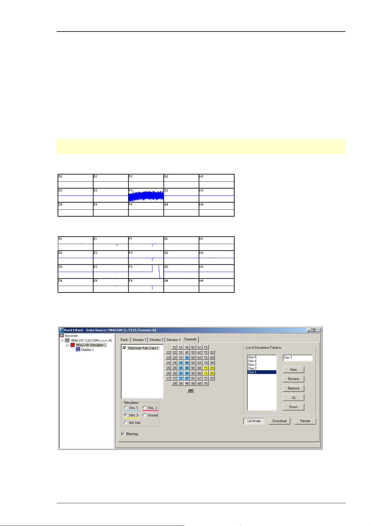
MC_Rack Manual
Dedicated Stimulation Electrodes
The function “Dedicated Stimulation Electrodes” can be used to further avoid stimulation artifacts
on the electrodes surrounding the stimulation electrode, which are sometimes not completely
removed by the blanking alone. Usually, the stimulation electrode will be connected to the
stimulator output only during the stimulation pulse, and afterwards be switched back to the
amplifier to be used as recording electrode. This sometimes causes switching artifacts
independently from the actual stimulation.
However, if the function “Dedicated Stimulation Electrodes” is active, the selected stimulation
electrodes will be constantly connected to the stimulator outputs. This causes permanent higher
noise on the selected stimulation electrodes, and makes of course recording on the stimulation
electrodes impossible, but almost completely removes residual artifacts. The images below show
stimulation on electrode F3 with and without “Dedicated Stimulation Electrodes” activated.
Note: The artifact suppression additional to blanking via “Dedicated Stimulation Electrodes”
is not available when using the “List Mode”.
“Dedicated Stimulation Electrodes” selected (X-Axis: 1000 ms, Y-Axis: +/- 500 μV)
“Dedicated Stimulation Electrodes” deselected (X-Axis: 1000 ms, Y-Axis: +/- 500 μV)
List Mode
Clicking the button List Mode opens an additional window: List of Stimulation Patterns.
In List Mode it is possible to generate and download a list of up to 256 user defined stimulation
patterns, which will then be applied automatically one after the other.
58
Page 65
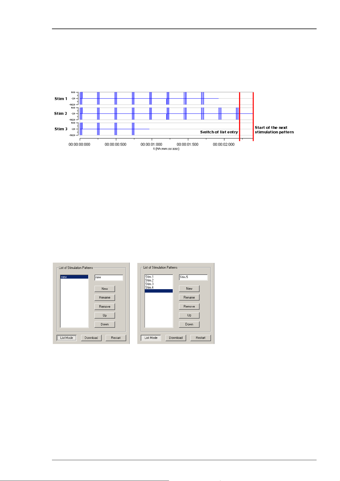
Step by Step Tutorial
When the List Mode is activated, the three stimulator units are coupled to a single starting
trigger. The starting trigger is set in the tab of the first stimulator unit, Stimulus 1. In Stimulus 2
and 3, the respective functions are disabled. To uncouple the stimulator units again, close the List
Mode dialog. The step from one stimulation pattern to the next in the list happens when the start
condition defined for Stimulus 1 occurs (for example, manual start, incoming trigger, real-time
feedback trigger) and all three stimulator units are idle. Please see the red bars on the picture.
However, the next pattern can only be started by the respective starting condition when the
previous stimulation paradigm, including all breaks, is completely finished.
That means, if one stimulation pattern of any of the three stimulator units is still running
when the condition occurs, nothing will happen. This also holds true when a stimulator unit
is not actually used in the currently active stimulation pattern.
Hence, the longest programmed stimulation pattern determines the minimum possible time
between two starting triggers, even if the respective stimulator unit is not actually used. It is
therefore advisable to set a stimulation pattern with a length of 0 on all unused stimulator units,
and keep all patterns as short as possible.
A stimulation pattern can contain single or multiple stimulation electrodes and may get an
user defined name. To create a list of different stimulation patterns, please do the following.
Click the button “List Mode”. There are two windows in the “List of Stimulus Pattern”. The small
window on the right side is for typing in a name for a pattern. In the window on the left side the
list of stimulation pattern will be displayed and arranged.
When opening the “List Mode” for the first time, the term “New” appears and the current
stimulation pattern is the first stimulation pattern in the list. To change the name, please
overwrite the name with the specific name of this pattern in the small window.
To insert a stimulation pattern, select with the mouse the position in the list where you want
to place the pattern. The line will be highlighted in blue. Type the specific name of this pattern
in the small window. Click the button "New" and the new list entry appears.
To append a pattern, select the line under the last list entry. The line will be highlighted in blue.
Type the specific name of this pattern in the small window. Click the button "New" and the new
list entry appears.
To rename a pattern of the list, select the pattern which will be highlighted in blue.
Then you can change the name of the pattern in the list. Please click the “Rename” button.
59
Page 66

MC_Rack Manual
The command “Remove” eliminates the pattern in the list, which is highlighted in blue.
With “Up” or “Down” you can move the patterns to arrange them in that sequence you
like to apply them.
Click “Download” to download the list of stimulation patterns to the internal stimulus
generator of the MEA2100 headstage.
To start the stimulation patterns in the list mode, please use the “Trigger Start” in “Stimulus 1”
tab of this dialog. The trigger start in Stimulus 2 and Stimulus 3 tab will not be available,
but all three triggers run simultaneously.
The stimulation patterns from the list will be applied one after the other and change every
time the start condition defined for Stimulus 1 occurs and all three stimulator units are idle,
as described above. When the end of the list is reached, the software jumps back to the first
pattern and continues. When the “Restart” button is pressed, the software jumps to the first
entry in the list, respectively.
Use of the Digital Channel in the MEA2100
In contrast to the other MEA- and ME-Systems from Multi Channel Systems, the 16 input bits
of the digital channel are not all accessible for external trigger signals, but are mostly used for
internal communication between the different components of the MEA2100 system. Only the
first four bits are connected to the physical DigIn connectors on the front side of the MEA2100
interface board. Most bits are permanently assigned to certain functions. However, these settings
can be customized if necessary. Please see the channels assignments from the following table.
Bit 0 DigIn 1 Digital In channel 1
Bit 1 DigIn 2 Digital In channel 1
Bit 2 DigIn 3 Digital In channel 1
Bit 3 DigIn 4 Digital In channel 1
Bit 4 Stimulus 1 Stimulation pattern on channel 1
Bit 5 Stimulus 2 Stimulation pattern on channel 2
Bit 6 Stimulus 3 Stimulation pattern on channel 3
Bit 7 Zero not connected
Bit 8 RF 1 Real-time feedback specification 1
Bit 9 RF 2 Real-time feedback specification 2
Bit 10 RF 3 Real-time feedback specification 3
Bit 11 RF 4 Real-time feedback specification 4
Bit 12 RF 5 Real-time feedback specification 5
Bit 13 RF 6 Real-time feedback specification 6
Bit 14 RF 7 Real-time feedback specification 7
Bit 15 RF 8 Real-time feedback specification 8
60
Page 67
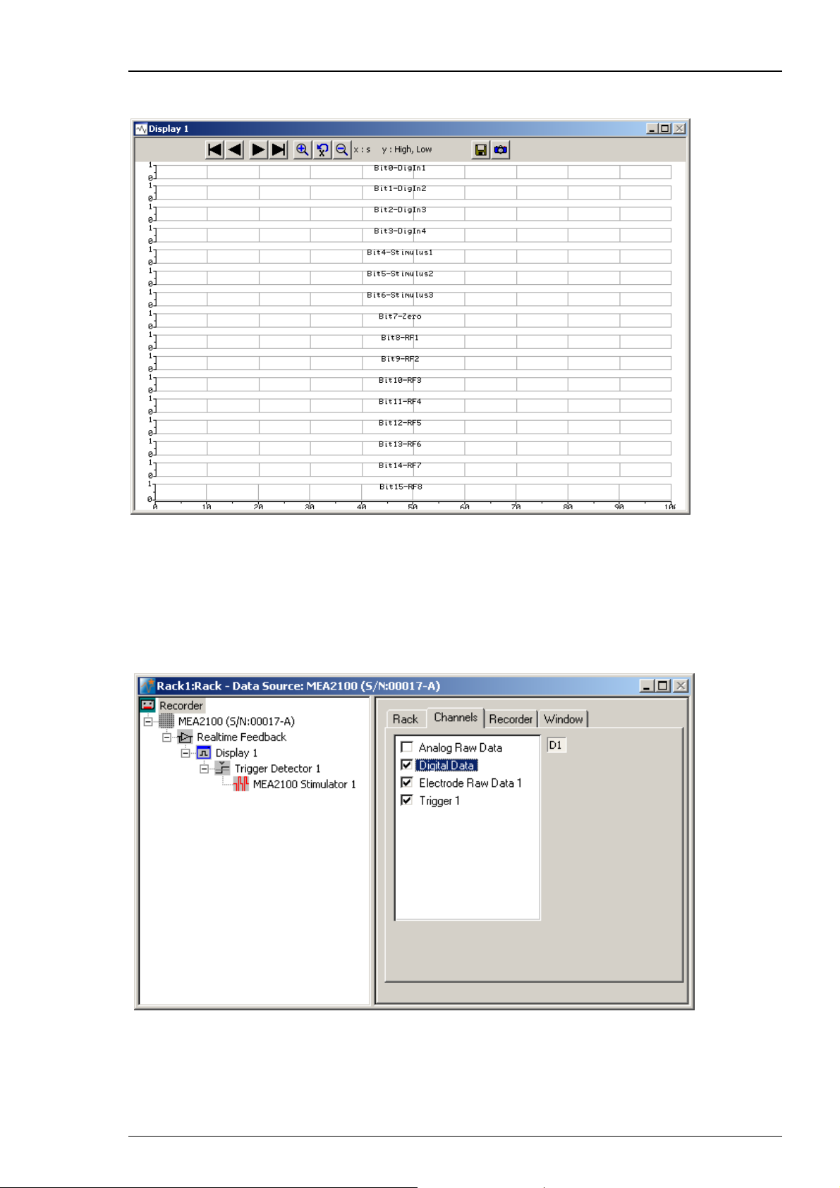
Step by Step Tutorial
To monitor the digital data stream you can use the “Digital Display” tool. If a MEA2100 device
is connected, the input bits will be labeled according to their function in the digital display.
If a MEA2100-32 device is connected, the “Real-time feedback” is not available, respectively
the real-time feedback specification 1 to 8 are not available. Therefore the input bits are used
for the digital inputs, bit 0 to bit 12 to digIn 1 to 13. The stimulation channels are connected
to the last three bits, bit 13 to stimulus 1, bit 14 to stimulus 2 and bit 15 to stimulus 3.
The channels are labeled according to their function in the digital display.
To record the digital data stream in the data file, please enable the respective check box
in the “Channels" tab of the Recorder tool.
.
61
Page 68
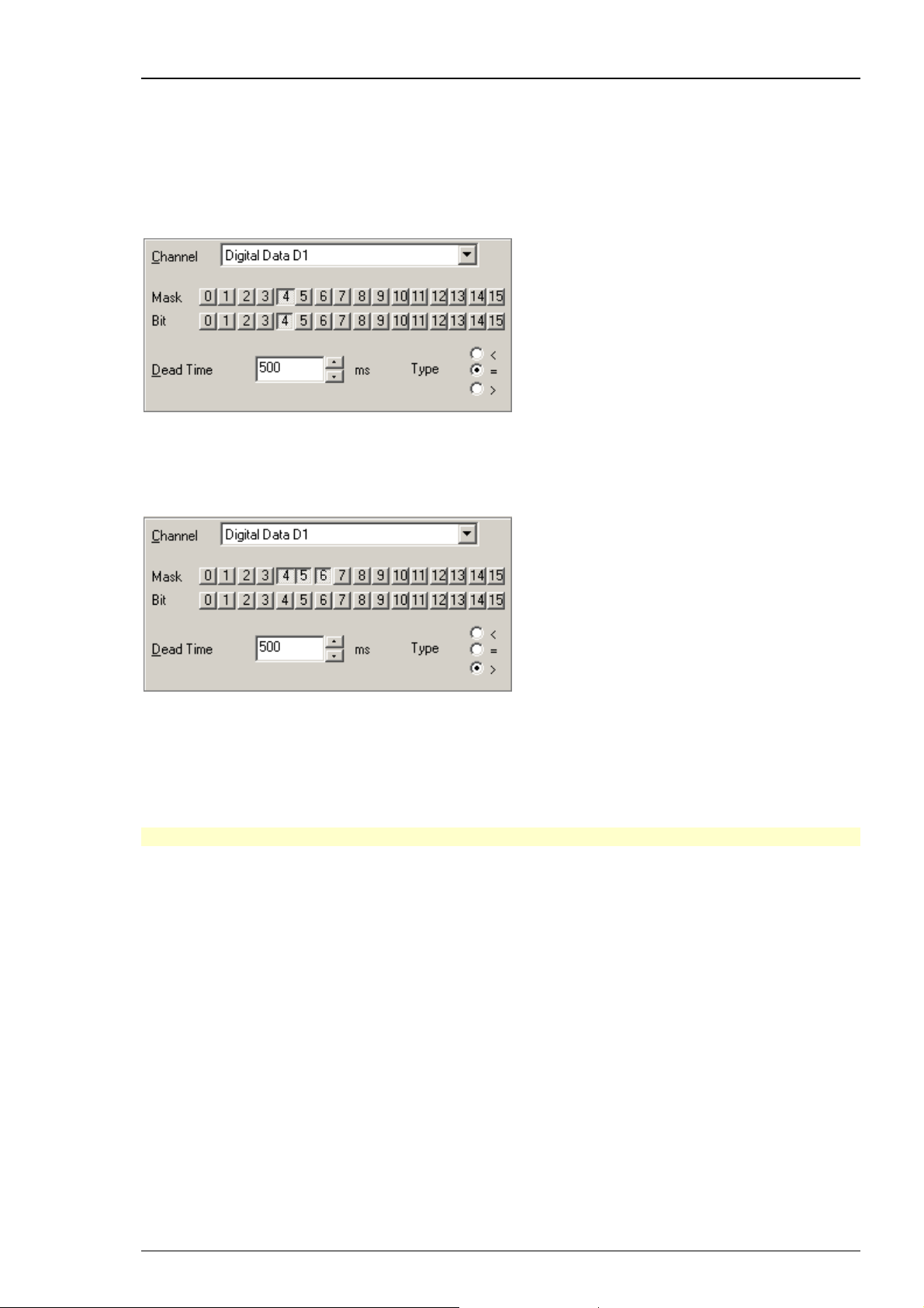
MC_Rack Manual
Triggering on Stimulation Pulses from Internal STGs
It is possible to trigger on stimulation pulses from any of the three internal stimulus generators.
The three internal STG units send a trigger signals with each stimulation pulse on bits 4, 5 and 6
of the digital channel, Stimulus 1 on bit 4, Stimulus 2 on bit 5 and Stimulus 3 on bit 6. Please see
chapter “Use of the Digital Channel in the MEA2100” for more details. So to trigger, for example
on each pulse of Stimulus 1, a Trigger detector in MC_Rack must be set to the Digital Channel,
bit 4. Please see screenshot below.
It is also possible to set the trigger detector to react on a signal from any of the three STG units.
This might for example be useful to start a triggered recording if a stimulus is applied from any
of the STG units. All three bits must be unmasked, and the bit value must be defined as > 0.
See chapter “Triggering on TTL Pulses” for more information.
Triggered recording and any instrument which is below the Trigger Detector in the virtual tree
of MC_Rack can now work in relation to the selected STG unit(s).
Real-time Feedback with MEA2100-System
Important: The Real-time Feedback function is not available for the MEA2100-32-System!
The interface board of the MEA2100-System is equipped with a high-capacity digital signal
processor DSP. By moving the detection and analysis of signals from the data acquisition computer
to the digital signal processor inside the interface, it is possible to run online filtering, analysis and
feedback stimulation in real-time. Please read also chapter “Real-time Feedback”.
At the moment, the real-time feedback is available for one instance of MC_Rack, that means
for one MEA2100-HS60, one MEA2100-HS120, or one MEA of a MEA2100-HS2x60.
By default, eight of the 16 bits of the digital channels are permanently assigned to the Real-time
Feedback function. For each of these eight bits, a different condition can be defined to release
a trigger signal. These eight bits can be monitored with the Digital Display. See also “Use of the
Digital Channel in the MEA2100”. The Real-time Feedback trigger signals are available in the
“Trigger Detector”, and can also be directly selected to start the internal stimulus generators.
See also chapter “Starting and Stopping the Stimulation”.
62
Page 69
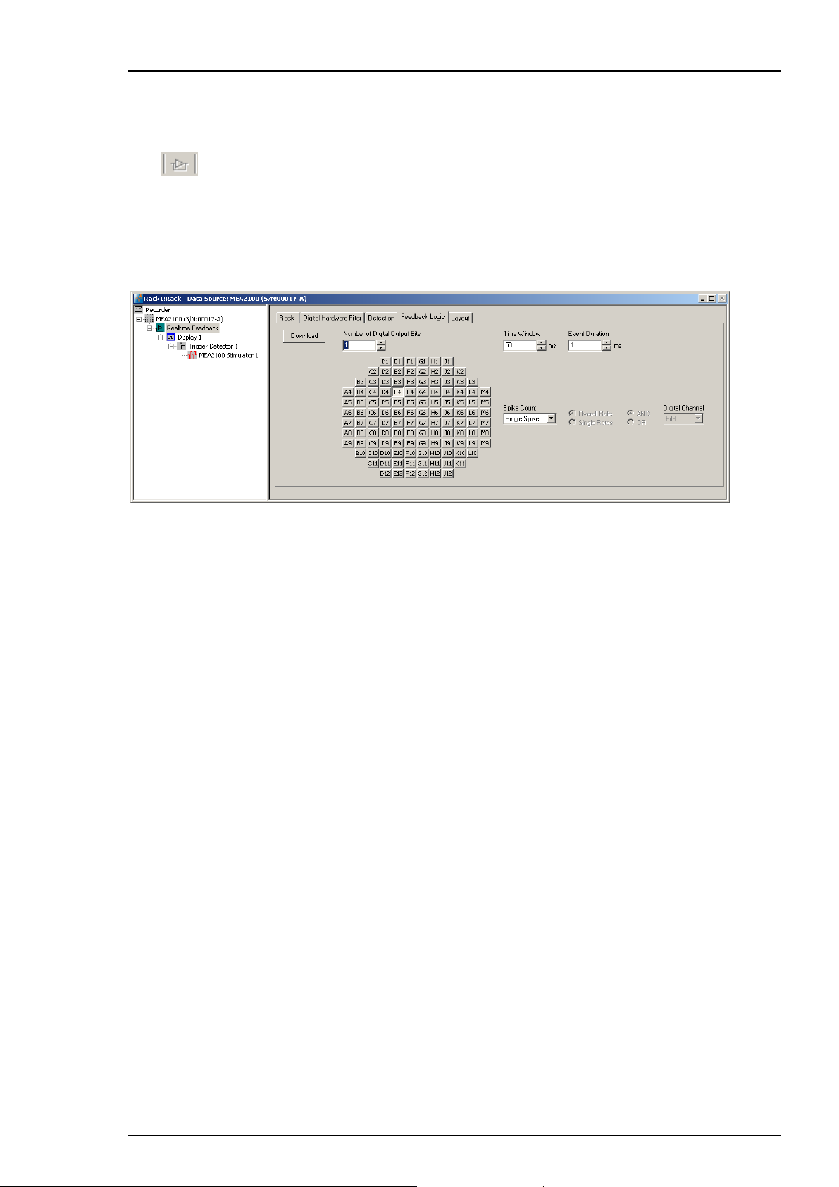
Step by Step Tutorial
Setting up the Real-time Feedback Software
The "Real-time Feedback" works the same way as with the other data acquisition systems of
Multi Channel Systems. The "Real-time Feedback" tool must be the first instrument under the
data source. Click "Edit" menu and add “Real-time Feedback” or click the real-time feedback
icon
However, the dialog of the “Feedback Logic” tab is different for MEA2100-Systems. While the
user can freely assign up o 16 different detection conditions to the 16 bits of the Digital Out
channel in the other MEA- and ME-Systems, the MEA2100 offers by default up to eight conditions
permanently assigned to eight bits of the Digital Channel. See also “Use of the Digital Channel
in the MEA2100”.
in the toolbar. Please also read the chapter “Real-time Feedback” for details.
63
Page 70
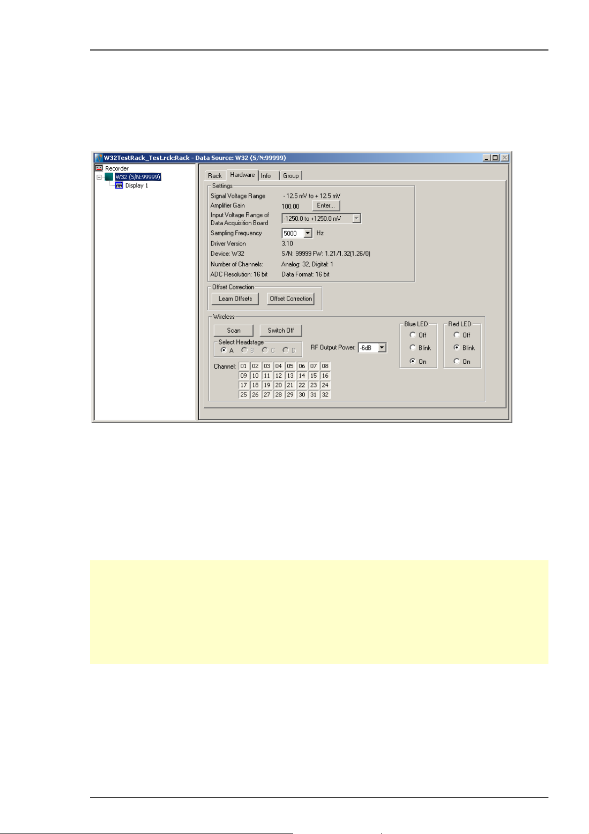
MC_Rack Manual
3.5 Wireless-System
3.5.1 Wireless System
When using a wireless in vivo recording system, the “Hardware” tab is modified.
Please see also chapter “Defining a Data Source” and read the Wireless-System manual.
The additional option “Wireless” is for hardware and software control of the wireless in vivo
recording system. One recording system can operate with up to four headstages simultaneously,
but it is only possible to record from one headstage at a time. The headstages come preconfigured
with different frequency bands by Multi Channel Systems MCS GmbH, and are labeled with A, B, C
and D. The “Scan” function searches the complete frequency band and will detect all active
headstages in range, and the radio buttons of the available headstages will become enabled
in the “Select headstage” window. Now you can select one of the headstages for experimental
processing only, the headstages do not work in parallel. In this example W8 headstages are
connected and “A” is selected. Individual recording channels can be activated (pressed in)
or deactivated. Inactivating channels can increase battery lifetime of the headstage.
Note: With all electrode channels, the maximum sampling rate for the 8-channel Wireless
Recording System W8-System is 20 kHz. It is possible to increase the maximum sampling rate
up to 40 kHz by deactivating at least four electrode channels. Please pay attention to the
sampling rate respectively, when using the W4-, W16- or W32-System.
Note: Deactivated channels will vanish from displays and will be automatically deselected
in analysis instruments (Analyzer, Spike Analyzer or the like). When reactivated, channels
automatically reappear in displays, but must be manually reselected in the “Channels” tab
of analysis instruments.
64
Page 71
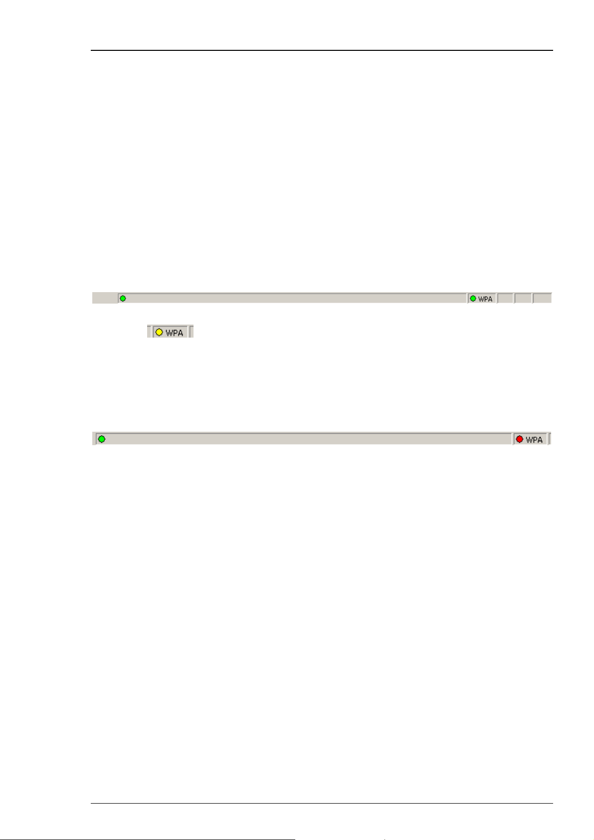
Step by Step Tutorial
The button “Switch Off” can be used to send the currently selected headstage from “Stand By”
mode to “Switched Off” mode, for saving battery energy. From this mode it is not possible to
switch the headstage on again via software control.
The blue LED mounted on the headstage of the Wireless-System indicates the recording phases.
It can be switched into three modes via radio button. Select “Off” if the laboratory animal
is disturbed by the light. Switching off the LED will save a little bit of energy. Select “Blink”
and the LED flashes during recording. Select “On” and the LED will be on permanently. This
feature can be used, for example for camera tracking. The W32-headstage is equipped with two
LEDs, a blue one and an additional red one which can be switched independently of each other.
The user has the same options to set the red LED. Both LEDs together improve the camera
tracking, because with two LEDs it is possible to track the orientation of the headstage.
Choose a “RF Output Power” value from the drop down menu. The smaller the value, for example
–18 DB, the longer the storage battery will support the recording, but the smaller the distance
between animal and receiver.
When operating a wireless in vivo system, there is an additional “WPA” status display for
visualizing the current status of the connected headstage in the status bar at the bottom
of the MC_Rack window.
The WPA status display appears in green color when the W8-System is running. The color turns
into yellow
three seconds after the data acquisition is stopped. The yellow color
indicates a stand by mode: The headstage is in energy saving mode, but can be started again
by pressing the MC_Rack “Start” button.
The WPA status turns red if the recording system does not have contact with the selected
headstage. This can be the case if the “Switch off” button has been used to send the headstage
into “Switched Off” mode, if the battery of the headstage is removed, or if the headstage is out
of transmitting range.
The status will automatically become green or yellow again if a headstage comes back into range.
65
Page 72

Page 73

4 MC_Rack Features
4.1 About MC_Rack Features
This section provides more detailed information on all features of MC_Rack. The topics
are in a systematic order.
4.2 Data Acquisition Settings
4.2.1 Data Source Setup
From the Edit menu, select Data Source Setup to configure the software according to your
MC_Card or USB based data acquisition and amplifier hardware. Data Source Setup is only
available as long as your current virtual rack is empty (that is, only a Recorder, but no MC_Card /
USB based data acquisition or Replayer in the virtual rack). Configure the channel layout first
and then set up the rack configuration, because it is not possible to change the data source setup
or channel layout later.
The data source and channel layout configuration is saved together with the rack (*.rck) file, that
is you can set up different racks for different hardware configurations. For example, the number
of electrode channels may vary in different ME-System setups. As a MEA-System user, you only
have to decide whether you have a MEA60-System (with a 64 channel MC_Card) or a MEA120System (with a 128 channel MC_Card) or a USB based data acquisition. The number of electrode
channels is fixed and cannot be changed for a MEA-System, but it can be altered in USB based
data acquisition systems.
You can also select Simulation as the data source. In Simulation mode, no data is acquired
from the MC_Card, but simulated waveforms are played and can be used for trying out MC_Rack
features. You can choose between sine waveforms on all channels, or the default simulation
(different waveforms on a number of channels). If no MC_Card is installed (or if it is not properly
installed), only Simulation is available as the data source.
67
Page 74

MC_Rack Manual
If you use MC_Rack together with devices which do not require a MC_Card, but use an internal
data acquisition and USB data transfer, the name of the connected device and its serial number
will appear in the right Data Source drop down menu, for example, USB-ME16 or USB-ME256.
On the left Data Source drop down menu is "USB MEA" displayed instead of MC_Card. Select
the desired device as data source.
Note: If you open a rack with a different channel layout, the channel layout of the opened rack
will be used. You can check the data source setup of the loaded rack by selecting the data source
in the tree view pane of the virtual rack, and clicking the Info tab, as shown in the following
screen shot.
Important: Please note that the data source layout you choose (1-dimensional or 2-dimensional)
does not only affect the numbering of the electrodes, but may also affect the compatibility with
third party programs, for example, the MEA Tools. Make sure you always select the appropriate
layout before setting up a virtual rack, and make always sure that the data source layout of the
loaded rack file is appropriate before starting the data acquisition.
68
Page 75
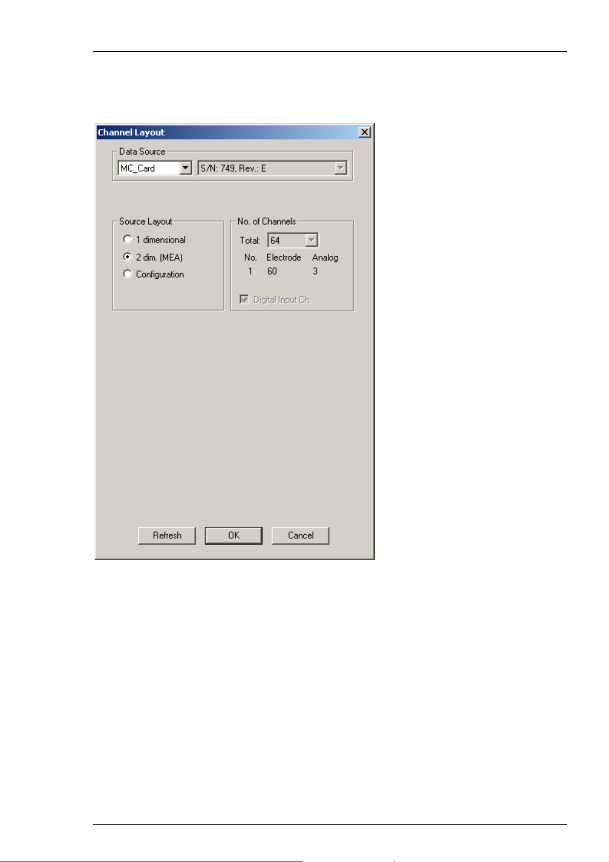
MC_Rack Features
MEA60-System
Select 2 dimensional (MEA) if you are using a microelectrode array (MEA) and a MEA60-System
with 60 electrode channels, three analog channels, and a digital channel. The number and layout
of channels is pre-configured and cannot be altered.
69
Page 76

MC_Rack Manual
MEA120-System
Select 2 dimensional (MEA) if you are using two MEA1060 amplifiers and a MEA120-System
with 120 electrode channels, 7 analog channels, and a digital channel. The number and layout of
channels is pre-configured and cannot be altered. Only three of the analog channels (A1, A2, A3)
are supported by the BNC connectors installed on the data acquisition computer.
70
Page 77

MC_Rack Features
Linear (custom) Layouts / ME-Systems
Select 1 dimensional if you are using any other type of data source, for example, a ME-System
or a custom setup. Define the number of channels provided by your hardware, and specify how
many electrodes (data amplified by the main amplifiers, for example, a MPA and a following
filter amplifier) and how many analog inputs (for example, from a temperature controller
or a microphone) are present. For the electrode channels, the original signal is calculated
automatically according to the gain settings in MC_Rack. Signals on the analog channels
are recorded "as is", with no respect to the gain.
Deselect the option Digital Input Channel, if you do not want to use the digital input channel.
One of the digital input bits can be used for triggering the recording on a TTL output of the
stimulator, for example. A typical configuration of an ME64-System would be 63 electrodes
and a digital channel.
71
Page 78

MC_Rack Manual
Data Source Configuration
Click "Configuration".
Configuration is an option that can also be used with MC_Card data acquisition (64 or 128
channels), but is recommended for the USB based data acquisition systems USB-ME64 / USBME/128 / USB-ME256. When selecting the configuration option, it is first necessary to adjust the
number of channels available. After that you can select the amplifier(s) and MEA(s) in use from
a drop down menu. To configure the MEA layout, please use the right drop down menu "MEA".
To configure the amplifier, please use the left drop down menu "Amp" (MEA1060 without
blanking circuit, gain factor 1200, and MEA1060BC with blanking circuit, gain factor 1100 for
MEA-Systems, and FA64I/S, FA32I/S for ME-Systems).
72
Page 79

MC_Rack Features
In MEA120-System it is possible to configure both amplifiers independent of each other.
Additionally it is possible to configure the MEA layouts of both MEAs A and B individually.
Note: Setting up the configuration of the data source is important for having the correct layouts
for MEA A and MEA B during the complete experiment.
73
Page 80

MC_Rack Manual
USB-ME16-FAI-System
The USB-ME16-FAI-System does not require a MC_Card, but uses an internal data acquisition.
Data can be transferred via USB 2.0 port to any data acquisition computer. Please see USB-ME16FAI manual for detailed information. Select USB MEA from the left Data Source drop down list.
The USB MEA device will be specified on the right Data Source drop down menu: USB-ME16
(S/N: 00001). The number in brackets is the serial number of the device. The data source layout
is 1 dimensional, with 16 electrode channels, and an additional digital channel.
74
Page 81
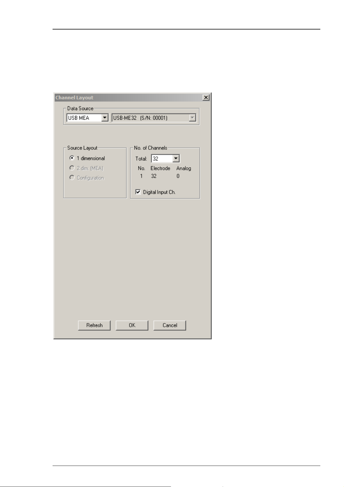
MC_Rack Features
USB-ME32-FAI-System
The USB-ME32-FAI-System does not require a MC_Card, but uses an internal data acquisition. Data
can be transferred via USB 2.0 port to any computer. Please see USB-ME32-FAI manual for detailed
information. Select USB MEA from the left Data Source drop down list. The USB MEA device will
be specified on the right Data Source drop down menu: USB-ME32 (S/N: 00001). The number in
brackets is the serial number of the device. The data source layout is 1 dimensional, with 32
electrode channels, and an additional digital channel.
75
Page 82
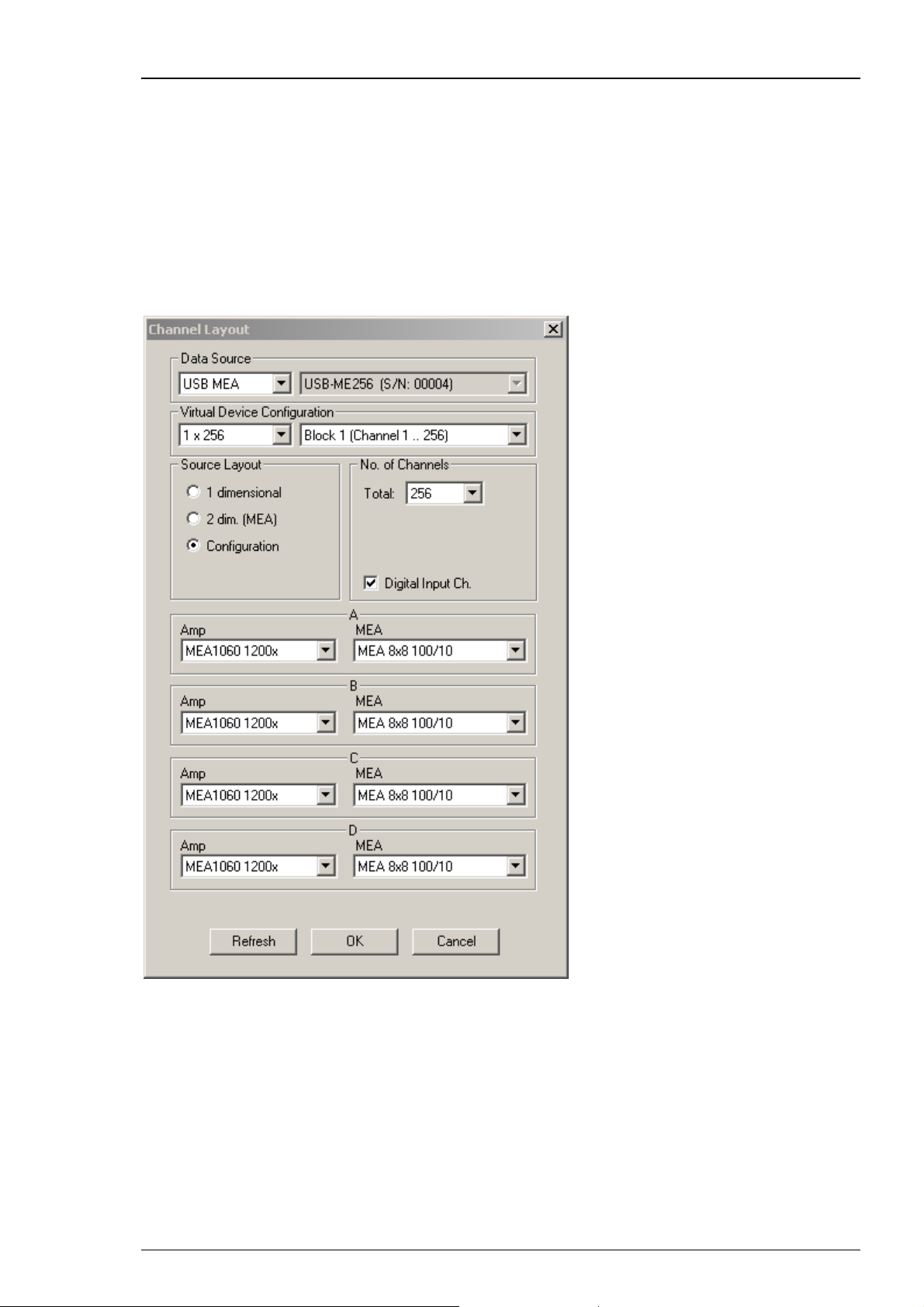
MC_Rack Manual
USB-ME64 / USB-ME128 / USB-ME256 Data Acquisition
The USB-ME64 / 128 / 256 data acquisition systems are in principle the same devices, except
for the total number of channels.
USB-ME256 Data Acquisition
The USB-ME256 is an external data acquisition device that uses USB 2.0 connection to transfer
digitized data to any connected computer. Please see USB-ME64 / 128 / 256 manual for detailed
information. Select USB MEA from the left Data Source drop down list. The USB MEA device will
be specified on the right Data Source drop down menu: USB-ME256 (S/N: 0004). The number in
brackets is the serial number of the device. Adjust the number of channels available.
76
Page 83

MC_Rack Features
Click Configuration in Source Layout. Choose 256 as total number of channels from the drop down
list under "No. of Channels".
In USB-ME256-System it is possible to configure four MEA1060 / MEA1060BC amplifiers
independent of each other. Click the amplifier drop down menus on the left side. Additionally
it is possible to configure the MEA layouts for up to four MEAs A and B, C and D independent
of each other. Click the MEA drop down menus on the right side.
77
Page 84

MC_Rack Manual
On the Edit menu, click Advanced Configuration to configure the software according to the
USB-ME256 hardware. Please see Advanced Configuration for detailed information. The dialog
Advanced Configuration is for optionally defining as many instances of MC_Rack software
as necessary. That means, you are able to work with several MC_Rack versions in parallel, for
example, when using the USB-ME256 with up to four MEA1060 amplifiers. With setting "Max.
Number of MC_Rack Instances = 4" in Advanced Configuration you can control each of the four
amplifiers independent from the others with its own MC_Rack software.
Note: Setting up the configuration of the data source is important for having the correct layouts
for MEA A, B, C and D during the complete experiment.
USB-ME128 Data Acquisition
The USB-ME128 device is in principle the same device as the USB-ME256, except for the total
number of channels, that is 128.
The USB-ME128-System does not require a MC_Card, but uses an USB 2.0 port for the data transfer
to the data acquisition computer. Please see USB-ME128 manual for detailed information. Select
USB MEA from the Data Source drop down list. The USB MEA device will be specified on the right
Data Source drop down menu: USB-ME128 (S/N: 0002), for example. The number in brackets is the
serial number of the device.
In USB-ME128-System it is possible to configure two MEA1060 / MEA1060BC amplifiers
independent of each other. Additionally it is possible to configure the MEA layouts for MEA A
and MEA B independent of each other.
On the Edit menu, click Advanced Configuration to configure the software according to the
USB-ME128 hardware. The dialog Advanced Configuration is for optionally defining as many
instances of MC_Rack software as necessary. That means, you are able to work with several
MC_Rack versions in parallel, for example, when using the USB-ME128 with two MEA1060
amplifiers. With setting "Max. Number of MC_Rack Instances = 2" in Advanced Configuration
you can control each of the two amplifiers independent from the other with its own MC_Rack
software.
Note: Setting up the configuration of the data source is important for having the correct layouts
for MEA A and B during the complete experiment.
USB-ME64 Data Acquisition
The USB-ME64 device is in principle the same device as the USB-ME256, except for the total
number of channels, that is 64.
The USB-ME64-System does not require a MC_Card, but uses an USB 2.0 port for the data transfer
to the data acquisition computer. Please see USB-ME64 manual for detailed information. Select
USB MEA from the Data Source drop down list. The USB MEA device will be specified on the right
Data Source drop down menu: USB-ME64 (S/N: 0002), for example. The number in brackets is the
serial number of the device.
In USB-ME64-System it is possible to configure the MEA1060 / MEA1060BC amplifier. Additionally
it is possible to configure the layout of MEA A.
Note: Setting up the configuration of the data source is important for having the correct layout
for MEA A during the complete experiment.
78
Page 85
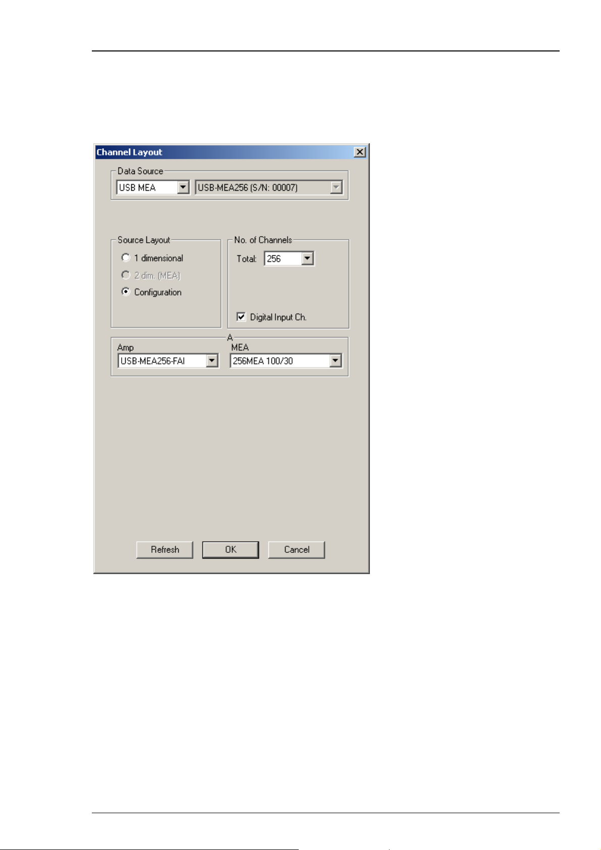
MC_Rack Features
USB-MEA256 Data Acquisition and Filter Amplification
The USB-MEA256 is an external data acquisition device with integrated filter amplifier that uses
an USB 2.0 connection to transfer digitized data to any connected computer. Please see USBMEA256 manual for detailed information. Select USB MEA from the left Data Source drop down
list. The USB MEA device will be specified on the right Data Source drop down menu: USB-MEA256
(S/N: 00007). The number in brackets is the serial number of the device.
79
Page 86
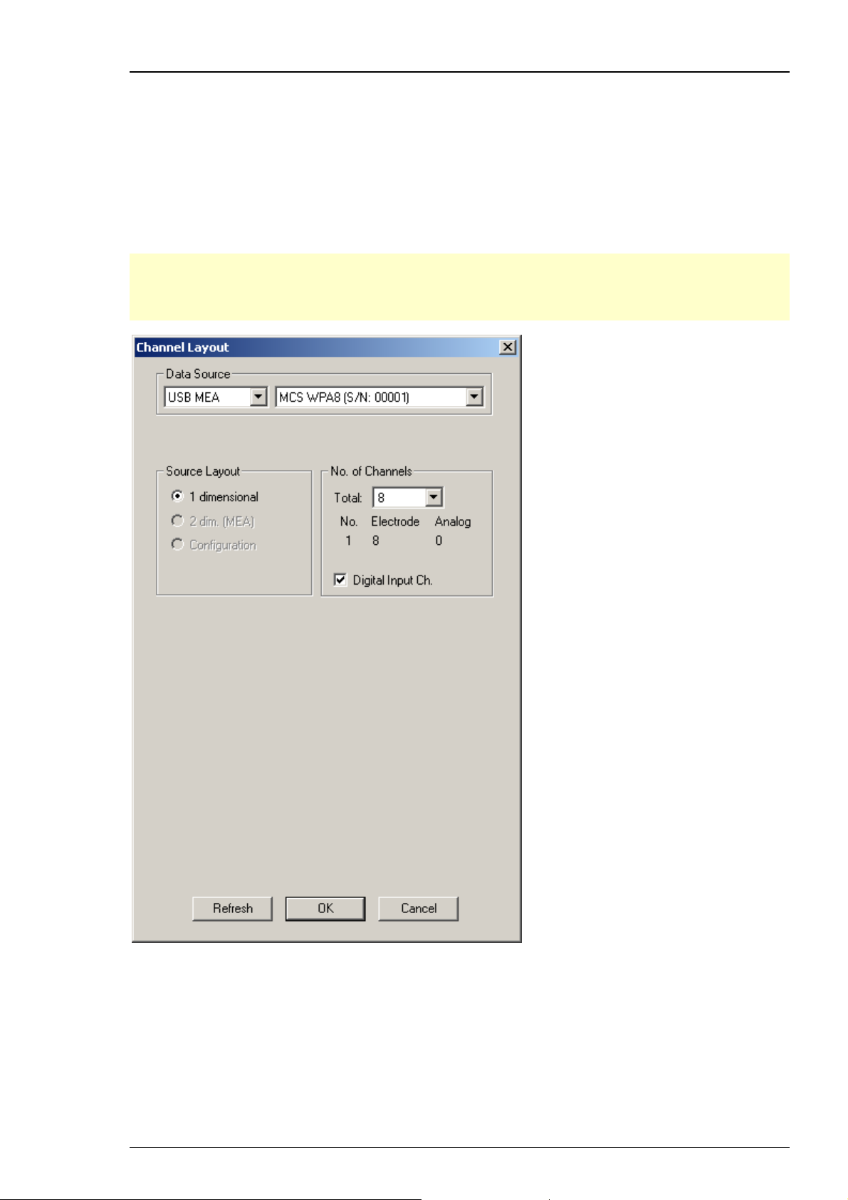
MC_Rack Manual
Wireless Recording System
The wireless in vivo recording system is the all-in one solution for amplifying, recording, and
analyzing in vivo data from eight channels that uses a wireless connection between headstage
and receiver and an USB 2.0 connection to transfer digitized data to any connected computer.
Please read the Wireless-System manual for detailed information. Select USB MEA from the left
Data Source drop down list. The W8-System device for example, will be specified on the right
Data Source drop down menu: MCS WPA8 (S/N: 00001). The number in brackets is the serial
number of the system. The data source layout is 1 dimensional, with 8 electrode channels and
an additional digital channel.
Note: With all electrode channels, the maximum sampling rate for the Wireless Recording System
is 20 kHz. It is possible to increase the maximum sampling rate up to 40 kHz by deactivating at
least four electrode channels. Please pay attention to the sampling rate respectively, when using
the W4-, W16- or W32-System.
80
Page 87
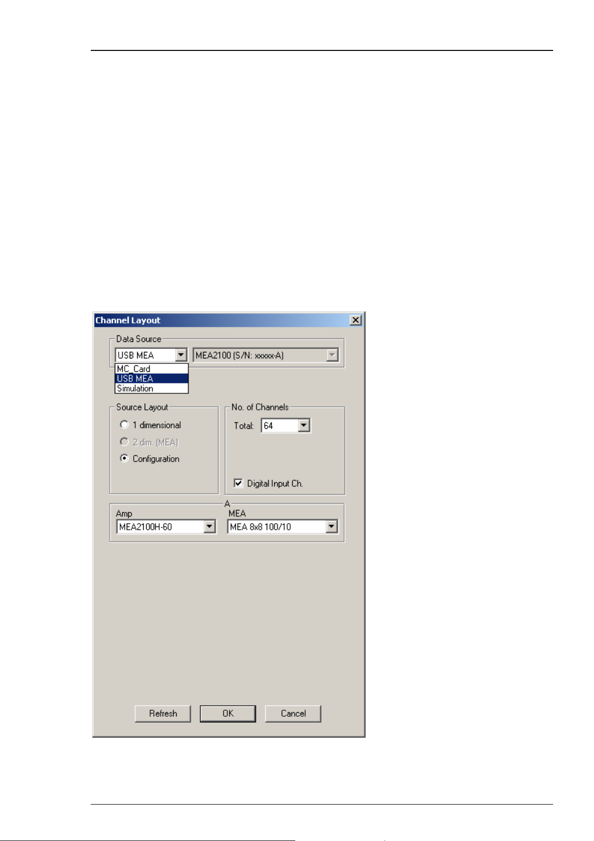
MC_Rack Features
MEA2100-System
The MEA2100 recording system is an all-in one solution consisting of headstage and interface
board. The MEA2100-System with integrated amplification, data acquisition, online signal
processing, and integrated stimulus generator. You can connect one or two headstages to the
interface board. The MEA2100-System uses an USB 2.0 connector per headstage to transfer
digitized data to any computer. Please read the MEA2100-System manual for detailed
information.
Select USB MEA from the left Data Source drop down list. The MEA2100 device will be specified
on the right Data Source drop down menu: MEA2100 (S/N: 0000-A).The number in brackets is
the serial number of the system, the character A labels the connected headstage, A is the first
headstage, B is the second headstage. It is possible to run up to two instances of MC_Rack per
headstage . Please read chapter "Advanced Configuration". Specify the “Number of Channels”
first: 32 electrode channels, when connecting one headstage with 32 recording and 12 stimulation
electrodes (MEA2100-HS32), 64 when connecting one headstage with 60 channels (MEA2100HS60) or 128 electrode channels when connecting two headstages with 60 channels (MEA2100HS60) or one headstage with 120 channels (MEA2100-HS2x60 or MEA2100-HS120) to the interface
board. Choose “Configuration” in the data source layout. Enable the check box for the digital
input channels. Select the correct headstage in the “Amplifier” drop down menu and specify
the type of MEA.
81
Page 88
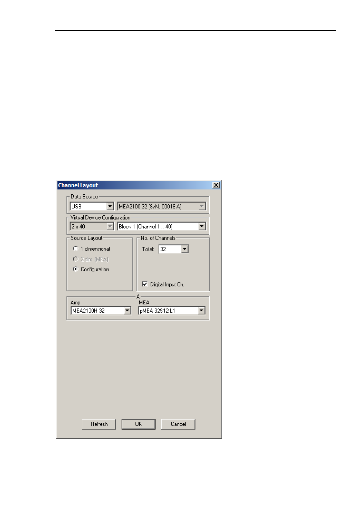
MC_Rack Manual
In MEA2100-System it is possible to configure two headstages independent of each other.
MC_Rack identifies two connected headstages as completely different devices. They are defined
via the character A or B in the serial number in the right "Data Source" drop down menu.
It is also possible to run two MC_Rack instances per headstage, for example for recording
from the 2x60 channels of the MEA2100-HS2x60 headstage separately. Please read chapter
"Advanced Configuration". Click the Amplifier drop down menus on the left side to configure
the "Amplifier". Additionally it is possible to configure the MEA layouts for up to two MEAs
A and B independent of each other. Click the MEA drop down menus on the right side.
MEA2100-32-System
The MEA2100-32-System is a descendant of the MEA2100-System with the same functions except
of the real-time feedback. Please read the MEA2100 Manual for detailed information. Select USB
from the left Data Source drop down list. The MEA2100-32 or MEA2100-2x32 device will be
specified on the right Data Source drop down menu: MEA2100-32 (S/N: 00018-A). The number
in brackets is the serial number of the device. The data source layout is Configuration, with 32
electrode channels, and an additional digital channel.
82
Page 89
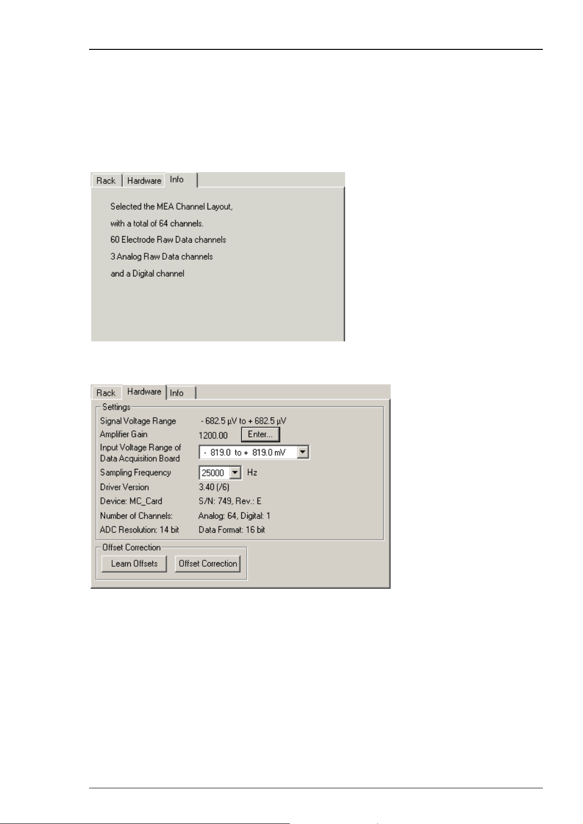
MC_Rack Features
4.2.2 Defining Hardware Settings
Before you start building a rack, configure first the software according to your hardware and
amplifier. The following example is for MC_Card and MEA1060 amplifier.
Select the MC_Card from your rack and click the Info tab to see the channel layout information
of your current rack. You cannot modify the settings anymore once you have added the MC_Card
or the Replayer to your rack. If the settings are not appropriate, remove the MC_Card from your
rack and change the channel configuration.
Click the Hardware tab to define the other settings, like the amplifier gain and sampling
frequency.
Signal voltage range
Please define first the "Amplifier Gain" and then the "Input Voltage Range of the Data
Acquisition Board". The "Signal Voltage Range" is calculated by dividing the "Input Voltage
Range of the Data Acquisition Board" and the amplifier gain factor.
83
Page 90

MC_Rack Manual
Amplifier gain
Specify the gain of the amplifier used. The gain is an intrinsic option of the device and can not be
altered. Make sure to use the gain the device actually has. Otherwise the recorded data will have
wrong voltage values. The default amplifier gain of a MEA1060 amplifier is 1200. For MEA2100Systems the amplifier gain is automatically set depending on the hardware. Any value between
1 and 1,000,000,000 is valid. The original signal is calculated automatically from the input and the
amplifier gain.
Important: The gain is a hardware property. You cannot change the gain of the amplifier with
MC_Rack. Make sure you use the gain that the amplifier actually has. This is especially important
if you use a PGA amplifier with programmable gain. Use the PGA-Control program to change the
PGA's gain and make sure you specify the same gain in the MC_Rack program as well. Otherwise,
the recorded data will have wrong voltage values.
Click Enter... to change the amplifier gain settings.
Input voltage range of data acquisition board
You can adjust the input voltage range of the MC_Card from +/- 400 mV to +/- 4 V with the
software control in the MC_Rack program. The lower the input voltage range, the higher is the
voltage resolution. You need a higher input voltage range if your biological sample generates
higher voltages, for example, cardiac signals from whole-heart preparations, and / or if the
amplifier gain is higher, so that the amplified output signal amplitude is higher, too. For spike
data, an input range of -819 to +819 mV will in most cases be fine, whereas for sum field
potentials like LTP that can be in the range of mV, you will probably need a higher input range.
For example, if you have a standard MEA amplifier with a gain of 1200, and choose a MC_Card
input voltage range of 819 to +819 mV, this results in a signal input range of -682 to +682 μV.
With a MC_Card with 14-bit resolution and an input voltage range of -819 to +819 mV, the
voltage resolution of the MC_Card will be 0.1 mV or 100 μV: A 14 bit resolution means 2
14
= 16384
available voltage values. 819 mV * 2 = 1638 mV total input voltage range / 16384 = 0.1 mV. For
a standard MEA amplifier with a gain of 1200, this means a resolution of 83 nV for the recorded
original signal.
Select the desired input voltage range from the Input Voltage Range of Data Acquisition
Board list.
84
Page 91

MC_Rack Features
Sampling frequency
As a rule of thumb, the sampling rate should equal five times the highest signal frequency for
a good digitized representation of the continuous analog signals. You would, for example, use
a 5 kHz sampling rate when using a MEA1060 amplifier with a cutoff frequency of 1 kHz. It should
be set according to the steepest slope of the expected signal. If the shape or amplitude of the
signal is very important for your analysis, an even higher sampling rate might be appropriate.
The maximum sampling rate is 50 kHz.
Please note that the sampling rate influences the amount of disk space needed and the computer
performance. Do not use a higher sampling rate than necessary. If you have a low signal
frequency (for example, from heart cells), you can use a much lower sampling rate than if you
have high frequency signals (for example, from neurons). (For more information on recording
and file size see "Recording Data").
If the sampling rate is too low, you will miss signals and / or see artifacts. The sampling rate
should also be at least twice the bandwidth of the MEA1060 amplifier. Otherwise, aliasing occurs.
See also the chapter "Filtering and Sampling Rate" for more information about aliasing.
Note: The sampling frequency should be at least five times the highest signal frequency
and at least twice the bandwidth of the MEA1060 amplifier.
Select the desired sampling frequency from the Sampling Frequency list.
Maximal Sampling Frequency using the data acquisition devices USB-ME256
and USB-ME128
Usually, the maximal sampling frequency for MCS data acquisition systems is 50 kHz. However,
when using some advanced features of the USB-ME256 and USB-ME128, some limitations apply.
The maximal sampling frequency that can be achieved with 256 channels is 40 kHz. This is possible
when using the USB-ME256 with the "virtual device configuration" 1 x 256 (Please see Advanced
Configuration). With the USB-ME256 and USB-ME128 it is also possible to split the data stream
into 2 x 64 or 2 x 128 and into 4 x 64 channels, respectively, again by using the "virtual device
configuration". These virtual machines can then be controlled independently by up to four
instances of MC_Rack. However, splitting the data stream into several virtual devices consumes
system performance. Therefore, the maximal sampling frequency is limited to 25 kHz when using
the virtual device configuration 2 x 64 (USB-ME128) or 2 x 128 and 4 x 64 channels (USB-ME256).
Offset Correction
An offset correction is generally not necessary, because the intrinsic DC offsets of the MCS
amplifier outputs and the MC_Card are very low in comparison to the signals of interest. You can
use the offset correction feature to remove even this low offset and reset all channels to zero.
Note: If you observe a large offset on any channel(s), you should contact your local retailer for
troubleshooting. The offset correction is not intended for removing large offsets, because the
offset correction will decrease the input voltage range.
1. Click Offset Correction to activate the offset correction..
2. Click Learn Offsets to perform an individual offset correction for each input channel. MC_Rack
takes 100 ms of the recorded data in the moment when the button is pressed to calculate the DC
offset. The mean of this 100 ms sweep is subtracted from the recorded data as long as the Offset
Correction button is pressed. The individual offset values for each channel are saved in the local
settings of the data acquisition computer and are only overwritten when you click Learn Offsets
again. Make sure you press the Learn Offsets button only when you have no real input signals
or irregular noise signals on the electrodes. To be on the safe side, you can connect a test model
probe to the amplifier.
85
Page 92

MC_Rack Manual
4.2.3 Channel Tool
The Channel Tool feature in MC_Rack allows the selection of one MEA electrode as reference
electrode. The tool works similar to the offset correction and influences the signal to noise ratio.
If there are problems with homogenous noise on all electrodes, the user is able to select one
electrode without signal as reference. The voltage value of this reference electrode will be
mathematically subtracted sample point per sample point from all electrode signals in the stream.
For example, a low frequency noise on all electrodes will be eliminated this way.
Note: Be careful to choose an electrode with noise only as reference electrode. If the reference
electrode contains signals too, the value of the signals will be subtracted together with the noise
value, and falsify the data.
Click the "Channel Tool" icon
from the Edit menu. The following dialog appears. Click the "Channels" tab.
in the main window toolbar, or select "Channel Tool"
Select the data stream you want to apply the channel tool: Electrode Raw Data in this example.
Select a "Reference electrode" from the "Reference electrode" drop down menu.
86
Page 93

MC_Rack Features
4.2.4 Grouping Multitrode Channels
Channels from electrodes with multiple channels (tetrodes or stereotrodes, for example) can be
grouped. This feature will help to analyze signals from multitrodes with MC_Rack or with other
analysis tools that can import MC_Rack files in the future. Right now, this feature is new and not
supported yet. But we recommend to use the grouping anyway to take advantage of improved
analysis features that will be made available in the future.
1. Add the MC_Card to your rack, and click the Group tabbed page to define the groups. This page
is only available if you use a 1 dimensional channel layout (see Setting Up the Channel Layout).
2. Define the number of electrodes with multiple channels.
On the right, the layout is updated accordingly. Each column represents a multitrode.
3. Define the number of channels per electrode.
The number of rows is updated accordingly.
4. Assign the appropriate channel numbers to each channel.
You can load or set up predefined channel maps. See Setting Up a Channel Map for more details
on the subject.
4.2.5 Simulation Mode
The simulation mode is available for users who are interested in learning more about the
MC_Rack features, but do not have a MC_Card or an USB based data acquisition available.
Without a properly installed MC_Card or other hardware, MC_Rack starts in Simulation mode
automatically. However, you can also switch from the default mode to the Simulation mode if you
have installed a MC_Card or an other device, for example, if you want to prove MC_Rack without
connecting an amplifier.
In Simulation mode, no data is acquired from the MC_Card or from USB based data acquisition,
but simulated waveforms are played and can be used for trying out MC_Rack features. You can
choose between sine waveforms on all channels, or the default simulation (different waveforms
on a number of channels). The third option is "File Source". Selecting this option an additional
window pane appears and you are able to browse through your folders.
If no MC_Card is installed (or if it is not properly installed), only Simulation is available as the
data source.
Warning: Make sure that you select the MC_Card
starting an experiment. You cannot use a virtual rack that uses Simulation as the data source
for experiments. With Simulation as the data source, no data will be acquired from the
MC_Card.
as the data source (not the simulation) before
87
Page 94

MC_Rack Manual
1. From the Edit menu, select Data Source Setup. Data Source Setup is only available as long as
your current virtual rack is empty (that is, only a Recorder, but no MC_Card or Replayer in the
virtual rack).
2. Select Simulation from the Data Source list. Select either Sine Waves, Default or File Source.
3. Choose a data source layout and the number of channels. For more information, see "Data
Source Setup".
With the option "File Source" in simulation mode you can open binary files with the extension
".raw" for simulating data. It is recommended to create these binary files with the software
MC_DataTool, but you can use different software just as well, however the format of the file
has to be binary.
Note: When creating a binary file with MC_DataTool, make sure to export as many channels
to the binary file as should be simulated later.
88
Page 95

MC_Rack Features
Open a binary file in MC_Rack in simulation mode. Data of this file is repeated in a infinite loop.
89
Page 96

MC_Rack Manual
g
4.3 Data Streams and Channels
4.3.1 Data Stream Types
A data stream can include several channels of the same data type. The term channel means
the data from a single MC_Card input pin, that is, electrode.
Several different data streams can be generated, handled, processed, and recorded by MC_Rack.
Data streams are either acquired by the MC_Card or an USB based data acquisition device,
for example, Electrode Raw Data, Analog Raw Data, and Digital Data; or they are generated
by MC_Rack when processing input streams, for example, Trigger, Parameter, Spikes and Filtered
Data.
You can adjust the number of analog and electrode channels according to your hardware
in the Channel Layout dialog box, up to a total of 256 channels. One digital input stream
with 16 channels (input bits) is available.
If you assign data to MC_Rack instruments, for example, the Recorder, you can select complete
data stream(s), or you can pick individual channels of interest from a data stream.
In the following list, all data streams available in MC_Rack are briefly described. Some more
complex data stream types are explained in more detail in the following chapters.
Definition of Data Stream Types
Electrode
Raw Data:
Analog
Raw Data:
Digital
Data:
Unprocessed analog data acquired from an amplifier, for example, from
a MEA amplifier for MEA electrodes or from a ME preamplifier like MPA8I.
The amplifier gain can be specified in MC_Rack, so that the original signal
is calculated automatically.
Analog non-amplified data that is directly delivered to the MC_Card via
BNC connectors, for example, channels A1, A2, A3 in the typical MEA layout.
In USB-MEA- or USB-ME-Systems four additional analog channels are available.
The data are delivered to the internal data acquisition, and send to the data
acquisition computer via USB High Speed. You can use it to record additional
information from external devices, for example, the heart rate, and so on.
You can connect the Sync Out of a STG (stimulus generator) to an analog input
to synchronize stimulus application and recording.
The 16 digital input channels of the MC_Card can be used to record additional
information from external devices as a 16-bit encoded number, or you can
connect the Sync Out of a STG (stimulus generator) to a single input bit for
synchronizing stimulation and recording. A digital IN /OUT connector is also
available in USB-MEA- and USB-ME-Systems. The 16 digital input channels are
represented as the Digital Data stream, that is, a stream of 16-bit values, each
bit (0 to 15) representing one digital input. Standard TTL signals are accepted as
input signals on the digital inputs. There are two possible logical states for each
bit: 0 (low = 0 V) and 1 (high = 5 V). The digital input channels are sampled
with the overall sampling rate selected in MC_Rack.
In the standard configuration, TTL signal sources can be connected to 3 BNC
inputs (input bits 0, 1, 2). Alternatively, a 68-pin socket supporting all 16 input
and output bits and a digital in / out extension with 16 BNC inputs and outputs
can be ordered as accessories. Unused input bits, which have an undefined
state, should be masked in the Trigger Detector.
For example, if the digital input bit 0 is set to high, the binary 16-bit value will
be 0000000000000001, or 1 as a decimal number. If channel 2 is set to high, the
value is (binary) 0000000000000010, or (decimal) 2, and so on. Any combination
of logical states of input bits is represented by the 16-bit value.
For more details on the use of the Digital Data stream for triggering MC_Rack,
please see the chapter Trigger Detector under MC_Rack Features. For more
back
round information on digital data and binary code, please see the
90
Page 97

MC_Rack Features
chapter About Digital Data and Binary Code under MC_Rack Features, General
Aspects.
Trigger: Generated by a virtual Trigger Detector. A trigger is used to control virtual
instruments or to record triggered data. For example, you can use signals from
an external device (for example, from the Sync Out of a STG) for triggering. For
electrode raw data, parameters, or filtered data, you can define a threshold for
triggering. You can define a bit pattern for using digital signals as a trigger.
You can also program an automatic time-based trigger. The manual trigger
allows the user to generate a trigger event manually during data acquisition.
Filtered
Data:
Spikes: Generated by a virtual Spike Sorter. Spikes can be detected by a threshold
Parameter: Generated by a virtual Analyzer. Several independent parameters can be
Averager: Generated by a virtual Averager. You can average sweeps to enhance the
Generated by a virtual Filter. You can use several filters with different cutoff
frequencies in your rack, for example, to remove background noise from your
signals or to separate spike activity from local field potentials.
or by their shape. Spike data streams can be overlaid or displayed as a Raster
Plot, sorted into up to three categories, or analyzed (the spike rate, for
example).
extracted from the same or separate input streams, for example, the peakto-peak amplitude, the spike rate, and so on.
signal to noise ratio. The averaged data can be saved and displayed. In addition
to the averaged data stream, a trigger data stream is created (Avg Trigger).
This trigger event is the time point of the last sweep. You need this trigger
information to access the averaged data later. See also Averaged Data for more
information.
4.3.2 Channel Selection
In the dialog box of the Recorder, Filter, Spike Detector and Analyzer tool, click the
Channels tab to assign individual channels to the according virtual instrument.
You can conveniently select and deselect channels with the button array on the right side.
You can choose single channels for recording, analyzing or displaying simply by clicking the
appropriate buttons.
The button array is arranged either in the layout of the MEA or in a linear fashion depending
on the currently selected stream and channel layout.
Selecting a data stream
The button array of the selected data stream is shown. The currently selected stream is
highlighted in blue. If you want to switch to the button array of another stream, select that
stream in the tree view to update the button array.
Click the desired data stream listed on the left. A button for each channel of the selected data
stream is shown.
Selecting a channel
The buttons represent single channels and have a toggle function. Click a button to select
or deselect a channel.
Click a button to select a channel. A selected channel button appears pressed in.
Click a selected channel again to deselect it.
91
Page 98
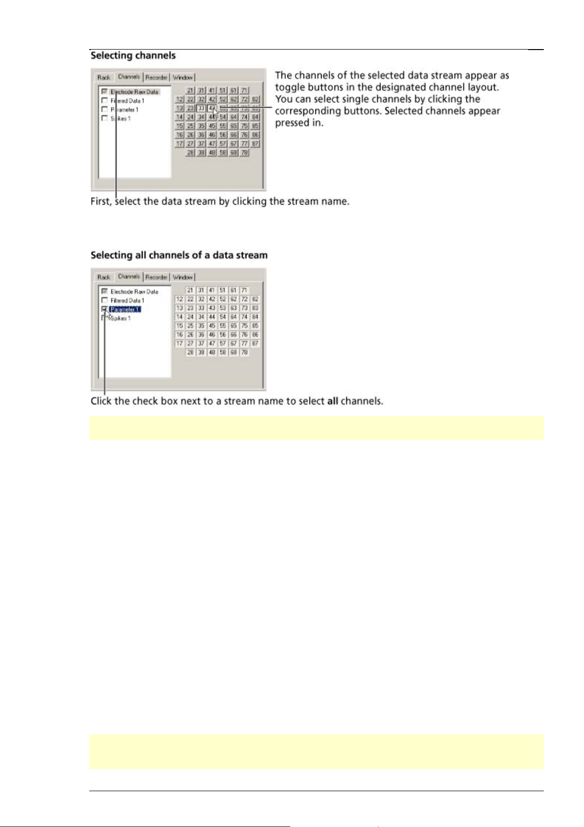
MC_Rack Manual
If you want to select or deselect all channels of a stream, check the box next to the stream name
in the tree view.
Note: Click a data stream first to display the corresponding button array. Make sure you have
selected the appropriate stream when selecting a channel.
4.3.3 Continuous and Triggered Data
You can create either continuous or triggered data files. Continuous data means that the data
is recorded / processed by the virtual instruments as a continuous data stream without regard
to a trigger event. Continuous data may still be synchronized to another system by starting the
recording of the file on a trigger event. Triggered data means that only data sweeps around a
specific trigger event are displayed, saved, analyzed, and so on. This has nothing to do with the
data stream types included in the data file: All data streams can in principle be recorded either
continuously or triggered, though it generally does not make much sense for all data stream
types. For example, the recording of spike cutouts would be a typical application for a continuous
recording (even though the spike data stream itself is not really continuous, it is treated as a
continuous stream in MC_Rack), and the recording of evoked field potentials like LTP would be
typical for a triggered recording (synchronized with the stimulation). Extracted parameters like
the spike rate are a special kind of data stream, because these data streams include only single
data points. Trigger settings in the Recorder do not apply to parameter streams.
A trigger event can be a biological signal crossing a threshold, or an external trigger event,
like a TTL pulse. The trigger event is specified with the Trigger Detector.
The Recorder, the Data Display, the Analyzer, and the Averager can be triggered by a trigger
event. You can define several triggers and assign them to separate virtual instruments. Use the
Window tabbed page of a virtual instrument to assign a trigger to it (Settings to assign a trigger
to the Averager, ROI for the Analyzer).
Note: MC_Rack stores the last two seconds of recorded data streams in a temporary virtual
memory. Therefore, it is not possible to display streams with sweeps that are longer than 2 s in
MC_Rack. You can record longer sweeps and export the data to other analysis programs, though.
92
Page 99
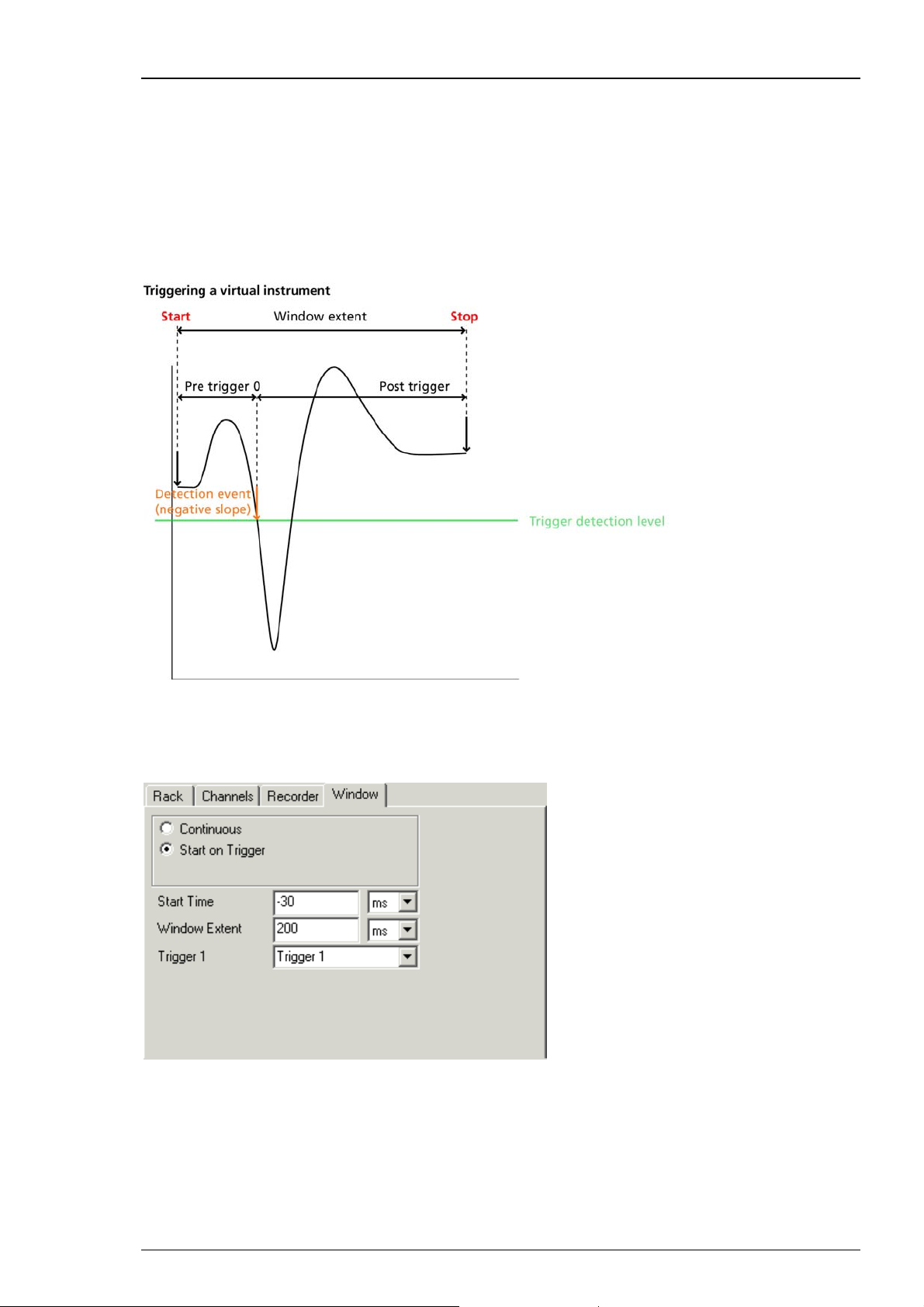
MC_Rack Features
When using the Replayer for replaying triggered data, make sure all other virtual instruments
in your rack are set up according to the data type. It is not possible to display triggered data
streams continuously (as there are "gaps" between the sweeps where no data was recorded).
The maximum x-axis range is limited by the sweep length. See the File Info of the Replayer to
obtain all necessary information on the data file, such as the sweep length.
Assigning a trigger event to a virtual instrument
You can trigger a virtual instrument by any Trigger data stream. The trigger event is referred
to as a time point of 0.
In the following example, the virtual instrument starts to process the data 30 ms before the
trigger and stops after a total time of 200 ms (170 ms post-trigger time). This results in 200 ms
sweeps. Please read chapter "Triggering MC_Rack on a stimulus" for more information about
"Window Extent" settings.
93
Page 100
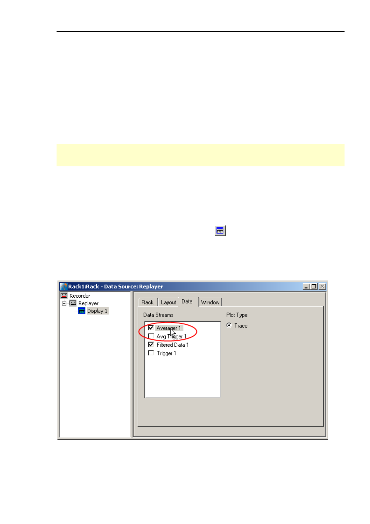
MC_Rack Manual
4.3.4 Averaged Data
Averaged Data, that is, a data stream generated by an Averager, is a special kind of triggered
data. Only the last sweep of each averager cycle is added to this data stream. Therefore, a socalled Avg Trigger is saved together with the Averaged Data stream (not to be confused with the
Averager Trigger that triggers the Averager). This Avg Trigger marks these last sweeps of a cycle.
If you assign averaged data to another instrument, the Analyzer or a display, for example, you
should use the Avg Trigger to trigger this instrument.
Recording averaged data
Together with the averaged data stream, the Avg Trigger is saved in the data file. You need
this trigger when you assign the Averaged Data stream to another instrument, for example
for triggering a Data Display.
Note: If you want to record averaged data and triggered data in the same data file, please
make sure that the Start Time and Window Extent of the Averager and the Recorder match.
Otherwise, you will not be able to review the Averaged Data stream later.
Replaying (or graphing) averaged data
In the following, it is described how to review an already save averaged data stream with the
Replayer. For more information on how to generate an averaged data stream (either online
during data acquisition or offline with the Replayer), please see chapter "Averager", "Averaging
Data Sweeps".
For replaying recorded Averaged Data streams, click
rack. Do not use the Averager, which is only used for generating Averaged Data streams!
In the tree view pane of the virtual rack, select the Data Display (here: Display 1), and click the
Data tabbed page. Select the Averaged Data stream (here: Averager 1). You can select the raw
data stream as well, to overlay the averaged data with the raw data, for example.
to add a Data Display to the virtual
94
 Loading...