

Page 1

HiClamp Manual
Page 2

Page 3

Information in this document is subject to change without notice.
No part of this document may be reproduced or transmitted without the express written
permission of Multi Channel Systems MCS GmbH.
While every precaution has been taken in the preparation of this document, the publisher and
the author assume no responsibility for errors or omissions, or for damages resulting from the use
of information contained in this document or from the use of programs and source code that may
accompany it. In no event shall the publisher and the author be liable for any loss of profit or any
other commercial damage caused or alleged to have been caused directly or indirectly by this
document.
© 2012 Multi Channel Systems MCS GmbH. All rights reserved.
Printed: 16. Mai 2012
Multi Channel Systems MCS GmbH
Aspenhaustraße 21
72770 Reutlingen
Germany
Fon +49-71 21-90 92 5 - 0
Fax +49-71 21-90 92 5 -11
info@multichannelsystems.com
www.multichannelsystems.com
Microsoft and Windows are registered trademarks of Microsoft Corporation. Products that are
referred to in this document may be either trademarks and/or registered trademarks of their
respective holders and should be noted as such. The publisher and the author make no claim
to these trademark.
Page 4

Page 5

Table of Contents
1 Introduction 1
1.1 About this Manual 1
2 Important Information and Instructions 3
2.1 Guarantee and Liability 3
2.2 Operator's Obligations 3
2.3 Important Safety Advice 4
2.3.1 High Voltage 4
2.3.2 Requirements for the installation 4
2.3.3 Handling of the motor driven axes 5
2.3.4 Handling of the chlorided silver wires 5
2.3.5 Handling of recording electrode needles 5
3 HiClamp 7
3.1 Welcome to the HiClamp 7
3.2 Hardware 9
3.3 Setting up the HiClamp 10
3.4 Mechanical Functionality of the HiClamp 12
4 Software 17
4.1 Program Concept 17
4.2 Installing the HiClamp Software 17
4.3 Starting the HiClamp 18
5 TEVC Recording Protocol 19
5.1 Preparations for Recording 19
5.2 Electrode Alignment 20
5.3 Test Model Cell 22
5.3.1 Testing the Amplifier with the Test Model Cell 22
5.3.2 Tuning the Amplifier 23
5.4 Selecting Oocytes for TEVC Recording 26
5.5 Starting a Recording Sequence 26
5.5.1 A first and simple example 26
5.6 Icons and the associated Effects 29
5.7 Data Acquisition Icons 34
5.7.1 Measuring multiple oocytes 35
5.7.2 The concentration activation curve 36
5.7.3 Recording Voltage-Gated Channel activity 36
iii
Page 6

HiClamp Manual
6
Data Analysis 39
6.1 Data File Organization 39
6.2 DataMining 40
6.3 DataMerger 46
7 Examples 55
7.1 The voltage activation curve of Kv1.4 55
7.2 The voltage activation curve of NaV 1.5 58
6.2.1 Measuring the current amplitudes 43
6.2.2 The e-Labbook of the HiClamp 45
6.3.1 Statistic 47
6.3.2 Example of a curve fitting 47
6.3.3 Example of curve fitting using “Global Fit” 52
Current-Voltage activation curve for KV1.4 56
8 Troubleshooting 61
8.1 Troubleshooting 61
9 Service and Maintenance 63
9.1 Service and Maintenance 63
9.1.1 Cleaning of the Basket 63
9.1.2 Replacing or Realigning 63
9.2 Preparation of Oocytes 65
9.3 Plating Oocytes 66
10 TEVC Recording Background 67
10.1 TEVC Recording Background 67
11 Appendix 69
11.1 Technical Support 69
11.2 Technical Specifications 70
11.3 About Preparation of Xenopus Oocytes 71
11.3.1 Materials 71
11.3.2 Chemicals 72
11.3.3 Oocyte Removal 72
11.3.4 Collagenase Digestion and Defolliculation 73
11.3.5 Selecting Good Oocytes 73
11.3.6 Plating Oocytes 74
11.4 Contact Information 75
iv
Page 7

1 Introduction
1.1 About this Manual
This manual comprises all important information about the first installation of the HiClamp
hardware and software and about the daily work with the HiClamp. It is assumed that you
already have a basic understanding of technical and software terms. Thus, no special skills
are required to read this manual.
If you are using the HiClamp for the first time, please read the "Important Safety Advice"
before installing the hardware and software. Please see chapter "First Use of the HiClamp",
where you will find important information about the installation of hardware and software.
The printed manual and online help are basically the same, so it is up to you which one you
will use. The help offers you the advantage of scrolling through the text in a non-linear fashion,
picking up all information you need, especially if you use the index and the search function.
If you are going to read larger text passages, however, you may prefer the printed manual.
The device and the software are part of an ongoing developmental process. Please understand
that the provided documentation is not always up to date. The latest information can be found
in the HiClamp help. Check also the Multi Channel Systems MCS GmbH web site
(www.multichannelsystems.com) for downloading up-to-date manuals.
1
Page 8

Page 9

2 Important Information and Instructions
2.1 Guarantee and Liability
The general conditions of sale and delivery of Multi Channel Systems MCS GmbH always apply.
The operator will receive these no later than on conclusion of the contract.
Multi Channel Systems MCS GmbH makes no guarantee as to the accuracy of any and all tests
and data generated by the use of the device or the software. It is up to the users to use good
laboratory practice to establish the validity of their findings.
Guarantee and liability claims in the event of injury or material damage are excluded when
they are the result of one of the following.
Improper use of the device.
Improper installation, commissioning, operation or maintenance of the device.
Operating the device when the safety and protective devices are defective and/or inoperable.
Non-observance of the instructions in the manual with regard to transport, storage, installation,
commissioning, operation or maintenance of the device.
Unauthorized structural alterations to the device.
Unauthorized modifications to the system settings.
Inadequate monitoring of device components subject to wear.
Improperly executed and unauthorized repairs.
Unauthorized opening of the device or its components.
Catastrophic events due to the effect of foreign bodies or acts of God.
2.2 Operator's Obligations
The operator is obliged to allow only persons to work on the device, who
are familiar with the safety at work and accident prevention regulations and have been
instructed how to use the device;
are professionally qualified or have specialist knowledge and training and have received
instruction in the use of the device;
have read and understood the chapter on safety and the warning instructions in this manual
and confirmed this with their signature.
It must be monitored at regular intervals that the operating personnel are working safely.
Personnel still undergoing training may only work on the device under the supervision
of an experienced person.
3
Page 10

HiClamp Manual
2.3 Important Safety Advice
Warning: Make sure to read the following advice prior to installations of the HiClamp. If you do
not fulfill all requirements stated below, this may lead to malfunctions, breakage, or even fatal
injuries. Obey always the rules of local regulations and laws. Only qualified personnel should be
allowed to perform laboratory work. Work according to good laboratory practice to obtain best
results and to minimize risks.
The product has been built to the state of the art and in accordance with recognized safety
engineering rules. The device may only
be used for its intended purpose;
be used when in a perfect condition.
Improper use could lead to serious, even fatal injuries to the user or third parties and damage
to the device itself or other material damage.
Malfunctions which could impair safety should be rectified immediately.
2.3.1 High Voltage
Electrical cords must be properly laid and installed. The length and quality of the cords must
be in accordance with local provisions.
Only qualified technicians may work on the electrical system. It is essential that the accident
prevention regulations and those of the employers' liability associations are observed.
Each time before starting up, make sure that the mains supply agrees with the specifications
of the product.
Check the power cord for damage each time the site is changed. Damaged power cords should
be replaced immediately and may never be reused.
Check the leads for damage. Damaged leads should be replaced immediately and may never
be reused.
Liquids may cause short circuits or other damage. Keep the power supply and the power cords
always dry. Do not handle it with wet hands.
2.3.2 Requirements for the installation
The HiClamp weighs more than 47 kg. Always grip it tightly and do not carry it alone,
but with the aid of another person.
The movements of the well plate carrier can lead to vibrations of the workbench on which
the HiClamp is set up. Therefore, the HiClamp must be set up on a rigid, vibration-free base.
The base must also be sufficiently solid to carry the weight of the device.
The HiClamp should be operated only in an air conditioned room. A room temperature
of 20 °C (or less) is recommended. Make sure that the device is not subject to direct sunlight.
It may overheat.
If the air cannot circulate freely around the external power supply, the device may overheat.
Do not shield the power supply by laying anything on top of the acryl glass cover.
The external power supply is only for use with the HiClamp. Do not connect it to any other
instrument.
4
Page 11

Important Information and Instructions
2.3.3 Handling of the motor driven axes
Do not move the axes by hand. Breakage may occur. Always use the software controls to move
in vertical or horizontal level.
The capillaries of the probe are sharp and may lead to injuries. Stay at a safe distance during
operation and protect your eyes. Especially take care not to move your hands in the range of
the vertical axis.
Do not try to plug anything other than 0.4 mm wire or the provided connectors into the
sockets of the recording axis. Damage may occur.
2.3.4 Handling of the chloride coated silver wires
The silver chloride coated silver wires are sensitive to light. Always keep them in dark during
storage. Make sure that all electrodes (including the reference electrodes) are still well-chlorided
before you start a recording. They should look dark grey, not shiny. The Ag/AgCl layer
deteriorates over time, leading to a DC offset and a voltage drift over time.
We recommend that you use the provided connectors to connect the electrodes to the vertical
axis. If you want to plug the silver wire directly into the sockets of the vertical axis, use only
0.4 mm silver wire for the electrodes. A wire with a greater diameter will damage the
connectors of the vertical axis irreversibly.
2.3.5 Handling of recording electrode needles
The needles are sharp and break easily. Always handle them with care.
In rare cases, the needles may splinter when pressure is applied. Stay at a safe distance
and protect your eyes.
Operation of the peristaltic pump
Empty the waste bottle at regular intervals, at least once a day if the HiClamp is in use.
The peristaltic pump must not be operated if the waste bottle is full.
Regular backups
You (or the administrator) should perform backups of the HiClamp data files at regular intervals
and to appropriate recording media for preventing data loss. Data loss may be caused by power
failure, system and software errors.
INI file modifications
If you remove or edit text of an INI file, the software may cause severe problems. Some INI files
relate to hardware functions. A modification of INI files may lead to malfunctions or even severe
damage of the hardware. Always keep a copy of the original INI file. Only advanced users should
modify program files. This warning message applies to all INI file modifications.
5
Page 12

Page 13
3 HiClamp
3.1 Welcome to the HiClamp
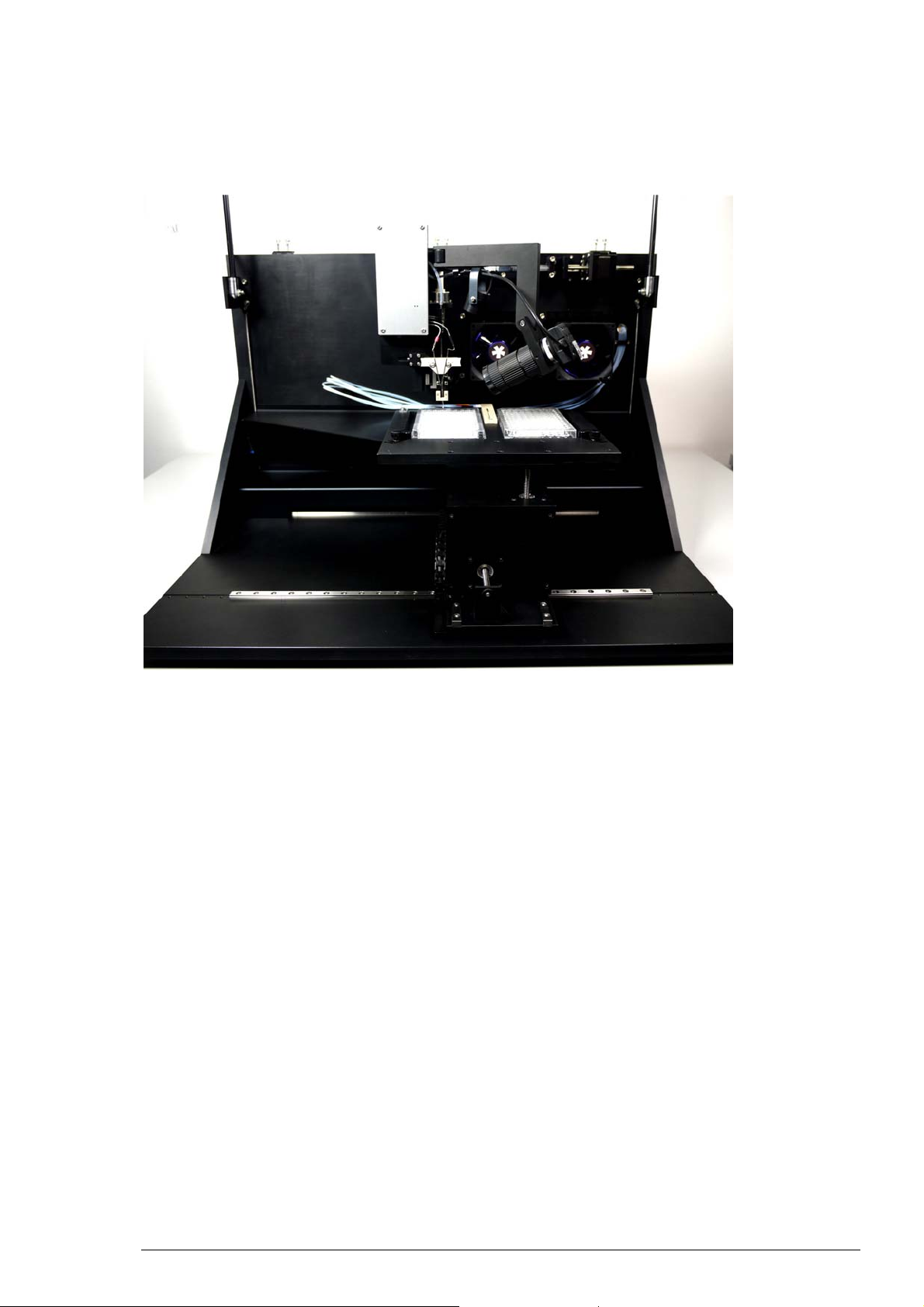
The HiClamp is a fully-automated all-in-one solution for high-throughput functional secondary
screening of drug targets based on the standard Xenopus expression system. The HiClamp allows
an automated recording using the TEVC method unattended and over night.
Main features
Compact and functional design, works fully computer-controlled.
High performance TEVC amplifier, records current of up to 105 μA.
Export features for further data evaluation.
Integrated washing station with a peristaltic pump based four channel perfusion system.
Non-destructive usage of test compounds.
Small sample volumes (~200 μl).
Operation summary:
The HiClamp functionality is based on the use of a novel system in which the oocyte is exposed
to a test solution by moving it physically into the solution of interest, whereas in a standard
system the solution is applied on the cell. The test solutions are disposed in a 96 microtiter plate
which is fixed on a table (in the left part). The oocyte is fixed in the support held (oocyte basket)
in the center of the automate and the table moves to immerge the cell in the desired solution.
The table moves in X, Y and Z direction under software control of very precise motors.
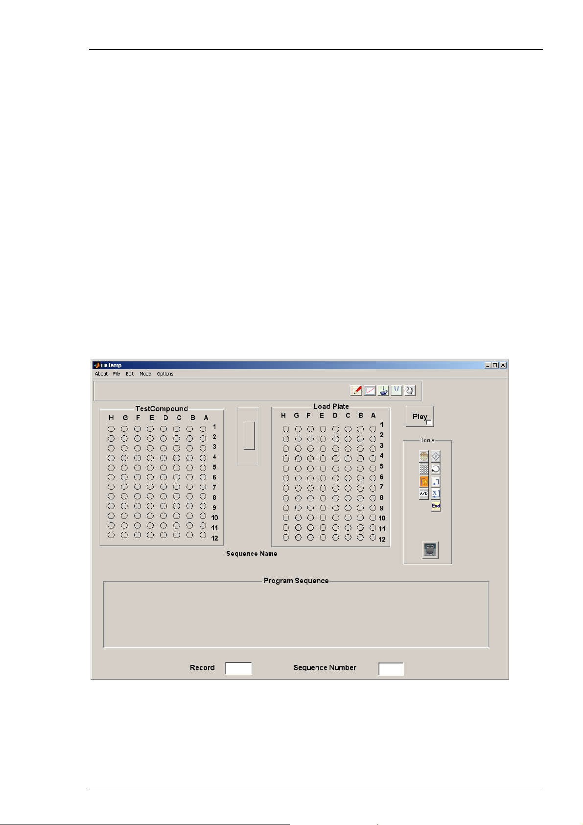
The HiClamp software program is an “icon based” program and was designed to simplify the
user interface while maximizing the possibilities for electrophysiological recordings. No special
programming knowledge is required to use the HiClamp software.
7
Page 14
HiClamp Manual
The program sequence is an ensemble of operations that are executed sequentially according
to a set of icons that are stored in the program sequence. Then, each icon corresponds to a given
procedure. For example, the oocyte icon will contain the type of message injected into the
oocytes, the number of cells available etc. At difference, the icon corresponding to the amplifier
will store the information controlling the amplifier gain, filter conditions, voltage clamp set up,
voltage steps etc. To access the content of a given icon the user double clicks on the icon stored
in the program sequence.
After defining the recording protocol, simply start the recording sequence by mouse click.
The run will proceed automatically until finished or interrupted by the user.
The HiClamp software
Operate the HiClamp, collect and evaluate the data by using the HiClamp software. The easyto-use graphical user interface of the HiClamp software makes daily work with the HiClamp
quick and easy. Recording is started by a single mouse click. The HiClamp controls the run
for all 96 oocytes automatically. Thus the recording can go on overnight, unsupervised.
You can define different experimental setups not only for different well plates, but also
for specific selections of wells on the same plate. Several control features to save time and
compounds are provided.
Automated analysis features are included in the HiClamp software, but you can export the data
to your custom evaluation software as well. You can graph the data and generate reports with
the HiClamp software. The large amount of data generated by the HiClamp can be managed
with the included DataMerger software.
8
Page 15
3.2 Hardware
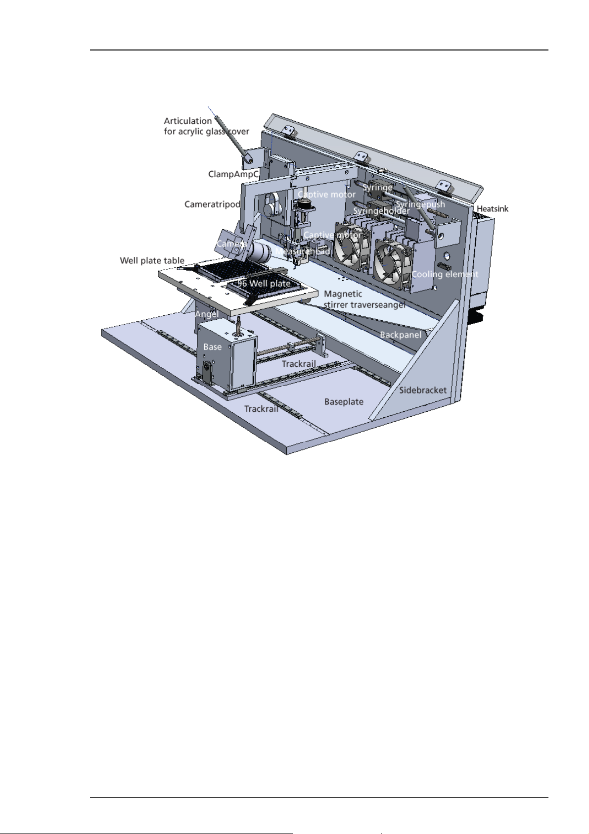
The HiClamp hardware
HiClamp
The HiClamp is compatible with standard lab equipment and can be easily integrated in your
working environment. Software controls replace any knobs on the device. The HiClamp is
straightforward and easy to operate; handling does not require special skills or special equipment.
Recording and cultivation of Xenopus oocytes is performed using disposable standard 96 well
plates, which are commercially available from several providers. The oocytes are plated into the
wells in a couple of minutes and can be kept for several days. The oocytes do not have to leave
the plate anymore; you can easily transfer the oocytes from the incubator to the HiClamp and
back again.
A quick alignment process under camera control guarantees that the glass microelectrodes
in the measuring head impale the oocyte precisely centered before recording.
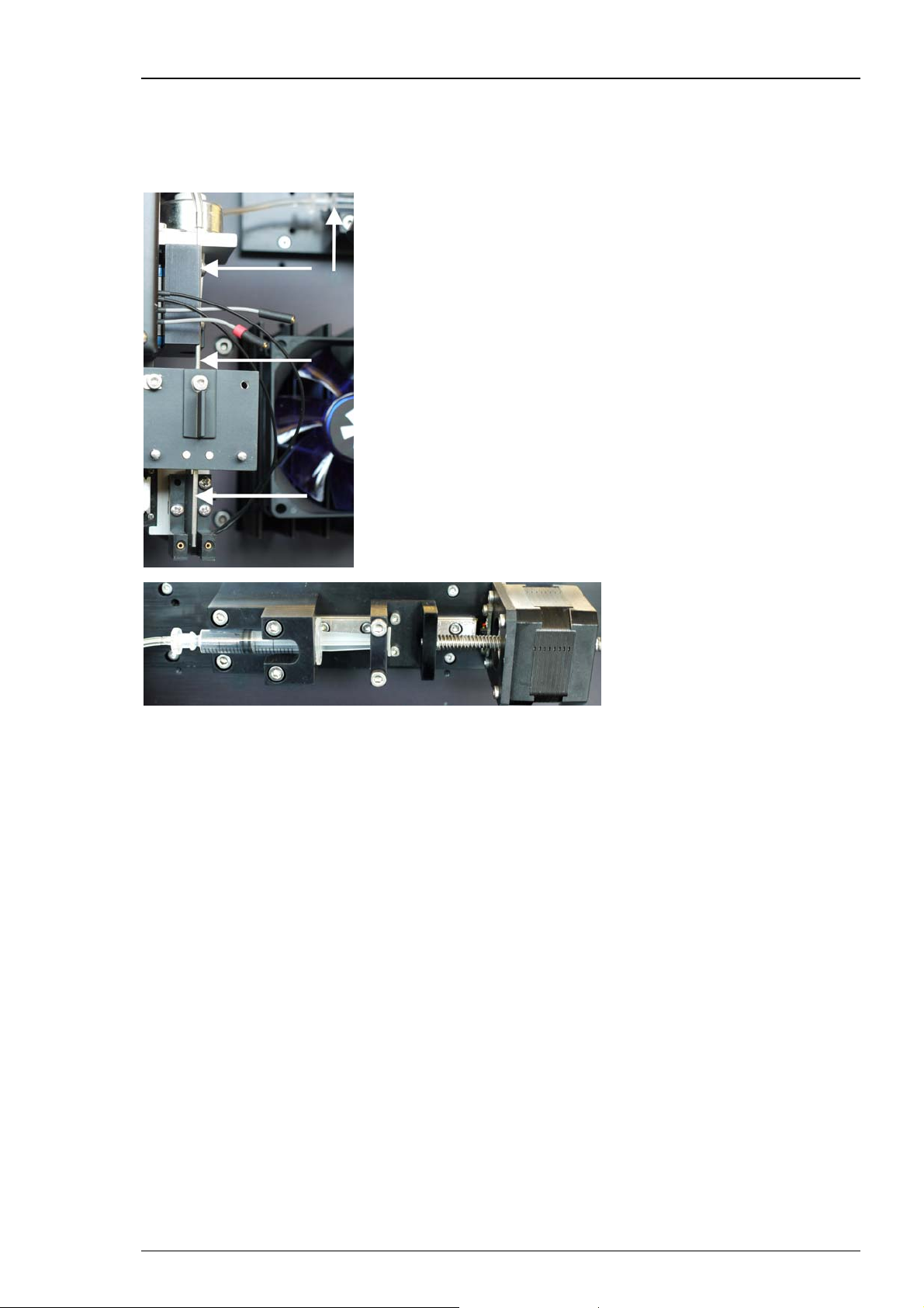
The ClampAmpC is a specifically designed digital TEVC amplifier and is completely automated.
The Syringe System arranges the aspiration of the cell when loading it into the basket via low
pressure.
The Perfusion System with inlet and outlet tubes and external peristaltic pump is for managing
the wash and test station placed between the 96 well plates on the table.
9
Page 16
HiClamp Manual
3.3 Setting up the HiClamp
Setting Up the HiClamp
1. Provide a power supply in the immediate vicinity of the installation site.
Important: Make sure that you do not place any AC voltage sources, that is, any electrical devices
or cables in the immediate vicinity of the HiClamp robot (especially not near the amplifier or near
any parts belonging to the perfusion system, for example, the bath reservoir or the waste bottle),
as they can introduce a 50 Hz noise or other electrical interferences to your recordings. Move
electrical devices or cables a few inches away if you observe any problems.
2. Place the HiClamp on a rigid, stable, and vibration-free base in an air conditioned room.
3. Place the computer and its accessories next to it. Make sure that you do not place the monitor
or the computer too near to the HiClamp robot or the perfusion system.
Connecting the HiClamp
Connect all cables as described below.
Warning: Carefully lay and secure the cords. Remember that someone could easily trip
over a loose cable.
Note: All electrical connections are clearly marked, and the plug coding prevents confusion.
The cords should be plugged in without the use of excessive force.
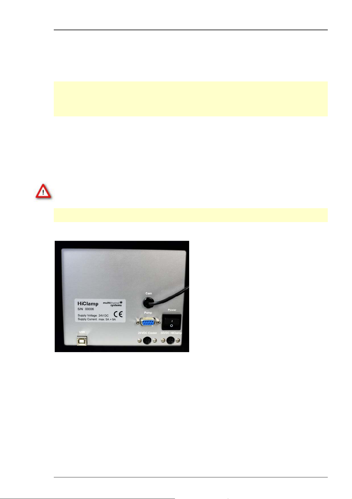
The following illustration shows the back panel of the HiClamp.
Connecting the video camera (Cam)
The USB cable of the video camera is fixed to the rear panel of the HiClamp.
Please connect the cable of the video camera to an USB port of the computer.
Connecting the peristaltic pump stand (Pump)
Plug the female connector into the male socket of the peristaltic pump. Then plug the male
valves connector into the female socket on the HiClamp's back panel.
On / Off Toggle Switch I / O (Power)
Toggle switch I / O for turning the HiClamp device on and off.
10
Page 17
HiClamp
Connecting the HiClamp to the provided computer (USB)
Connect the HiClamp directly to the provided computer by the provided USB cable. The
appropriate connector on the rear panel of the computer is tagged with a "HiClamp" label.
Note: Please do not use one of the USB 3.0 ports of your computer for connecting the HiClamp.
Power In for the HiClamp (24 VDC HiClamp)
Connect the HiClamp to the power supply unit here. This power supply powers the HiClamp
main unit only.
Power In for the Cooler (24 VDC Cooler)
Connect the Cooler to the power supply unit here. This power supply powers the Cooler main
unit only.
Warning: If the air cannot circulate freely around the external power supply, the device
may overheat. Do not shield the power supply by laying anything on top of it. Make sure
it is not exposed to direct sunlight.
Note: All electrical connections are clearly marked, and the plug coding prevents confusion.
The cords should be plugged in with no excessive force.
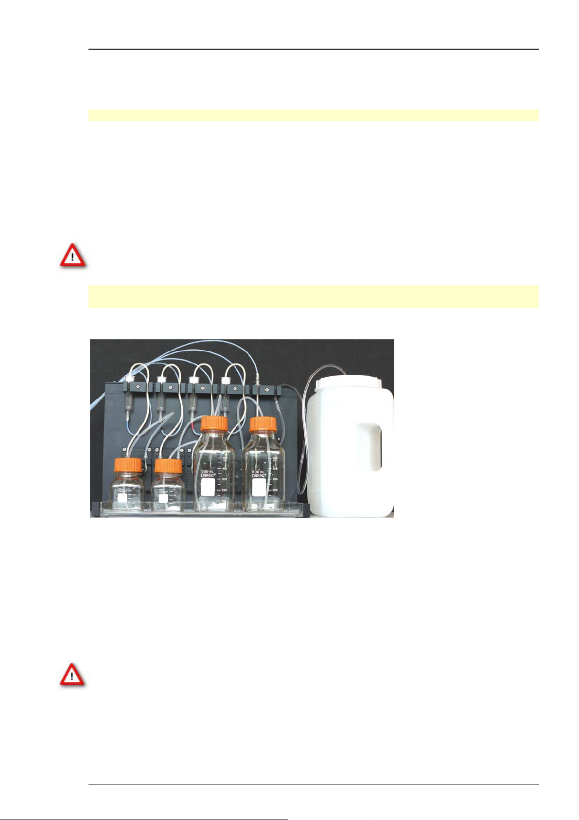
The Peristaltic Pump Perfusion System with four Channels
For washing the oocyte between two measuring circles there is a washing station placed
between the well plates. The washing station can also be used for applying test compounds
to the cells.
The test and washing station is connected to five tubes: Four inflow and one outflow channel.
The fifth channel is connected to the waste bottle via peristaltic pump which is running
backwards. Please read chapter “Mechanical Functionality of the HiClamp”.
The operation of the perfusion system is fully software controlled.
Do not start the perfusion without double checking the connected bottles and the waste bottle.
Warning: Spilled liquid can damage or even completely destroy the electronics of the
HiClamp. Please be careful when setting up the perfusion system and when starting the
perfusion of the washing station. Take care that inlet and outlet tubings are properly
connected so that flooding of the table and the mechanical components of the HiClamp
is efficiently prevented.
11
Page 18
HiClamp Manual
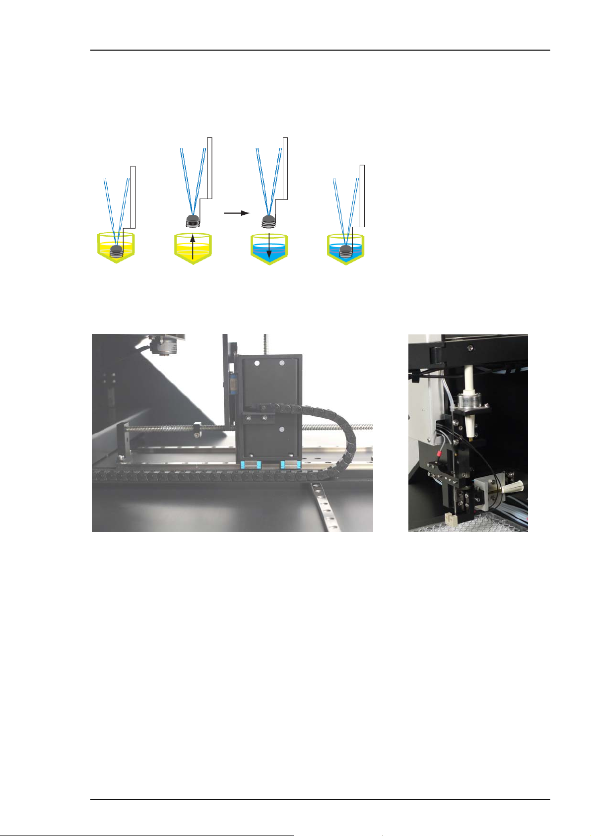
3.4 Mechanical Functionality of the HiClamp
The specific characteristic of the mechanical components of the HiClamp device is their mobility
in three dimensions. The movement of the table complex in dependency of the movement and
adjustment of the measuring complex is the main idea of the HiClamp’s functionality.
The table complex moves on track rails in X, Y and Z direction under software control of very
precise motors.
The basket with the oocyte inside moves in Y direction only, but is not moving during recording
minimizing recording artifacts and oocyte damage during transport.
The HiClamp is based on a innovative system in which the cell (or preparation) is exposed to
a test solution by moving it physically into the solution of interest, whereas in a standard system
the solution is applied on the cell. The provided solutions are disposed in a 96 well plate which
is fixed on the left part of the table. The cell (or preparation) is carried in the basket in the center
of the HiClamp. After adjustment of table complex and measuring head, the basket keeps
stationary while the table moves to immerge the cell in the desired solution.
12
Page 19
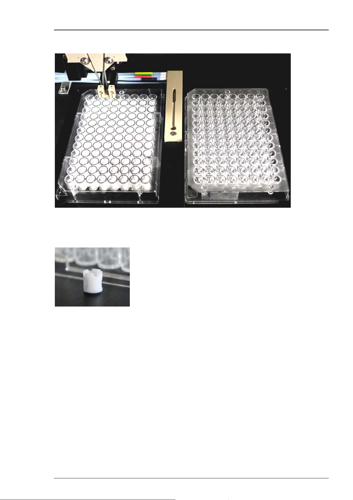
For washing the cell between two measuring cycles there is a washing station placed
between the well plates.
HiClamp
The well plate on the right hand side is called “Feeder Plate” and contains the oocytes to be
tested. The well plate on the left hand side is called “Compound Plate” and contains the solutions
of interest. Each compound well should be filled with 230 μl. Additionally a micro stirrer is placed
inside which is moved by magnetic forces.
Immersion of the oocyte in the compound liquid is not sufficient to ensure a quick access of the
drug to the cell membrane. Passive diffusion of the molecule of interest alone to the membrane
would be too slow and mechanical stirring is therefore indispensable to ensure a fast access of the
compound to the membrane protein. Miniature stirrers were specially designed and conceived
with a proprietary structure to allow mixing of the solution in the 96 well format. Placing the
stirrers in the microtiter wells offers the additional advantage to reduce the volume of the well
and therefore to minimize the amount of solution required for the experiment.
13
Page 20
HiClamp Manual
Automated Loading of Oocytes from Compound Well Plate
The oocytes are stored in the 96 well plate called feeder plate on the right side of the table. They
will be automatically transferred to the compound plate on the left side for measuring the cells.
For transportation and measuring the oocytes are carried in the basket.
14
Page 21
HiClamp
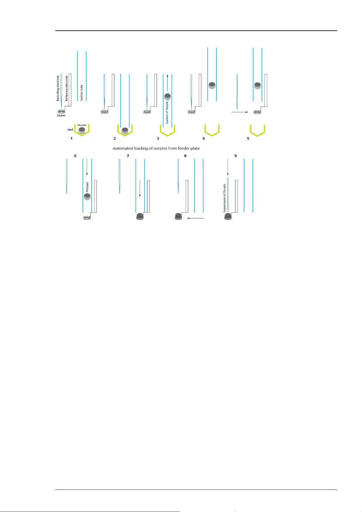
Cartoon of the automated oocyte transport from 96-well feeder plate to the oocyte basket:
The oocyte is in the selected well of the feeder plate (1). The suction tube is lowered into the
well (2). The oocyte is aspirated (3). The suction tube moves to the basket (4). The suction tube
is lowered directly above the basket (5). The suction tube emits the oocyte (6). The oocyte is
placed in the basket (7). The basket moves with the oocyte beneath the position of the TEVC
electrodes (8). The electrodes are lowered and the oocyte is impaled for recording (9).
Finally, the recording sequence starts when the oocyte is successfully impaled and an appropriate
resting potential is measured by both intracellular glass electrodes.
15
Page 22

Page 23

4 Software
4.1 Program Concept
To maximize the system capacity while simplifying the use of the HiClamp device for data
acquisition and analysis, HiClamp and the corresponding data analysis program are built around
an object oriented concept. In such concepts the object, this is the icon, contains information to
effectuate the appropriated and desired operation. In HiClamp, objects are represented as icons
that symbolize the action to be executed.
For example, the icon above symbolizes the loading plate that contains the oocytes to be
measured. For execution the information of this object, the HiClamp automatically loads the
next available oocyte, measures the resting potential and puts the oocyte back in its original
position if appropriate conditions, that means the holding potential is not met.
This icon based system offers several advantages that become evident when considering the
analysis. Data analysis is effectuated by a few clicks on the appropriate icons, which avoids
the learning of a specific language while offering the maximal flexibility. Results obtained
from different days of experiments are powerfully managed and merged by a module of the
software and results can be presented either as graphics or excel compatible data report sheets.
4.2 Installing the HiClamp Software
System requirements
Software: One of the following Microsoft Windows ® operating systems is required: Windows 7,
or XP (English versions supported with the NT file system). Other language versions may lead to
software errors.
Hardware: An USB 2.0 High Speed serial bus must be provided for the communication between
the HiClamp and the computer. 1 GB RAM working memory is strongly recommended.
Recommended operating system settings
The following automatic services of the Windows operating system interfere with the data
storage on the hard disk and can lead to severe performance limits. These routines were designed
for use on office computers, but are not very useful for a data acquisition computer.
Turn off Windows System Restore.
Turn off automatic Windows Update.
Turn off Optimize hard disk when idle (automatic disk fragmentation).
Deselect Windows Indexing Service for all local disks.
It is also not recommended to run any applications in the background when using the HiClamp.
Remove all applications from the Autostart folder.
17
Page 24

HiClamp Manual
Caution: You have acquired a high performance data acquisition and analysis computer.
Do not modify the system, do not install new hard- or software, or another operating system
without asking MCS or your local retailer for advice. MCS recommends not to install virus scanners
or firewalls because these programs are known to interfere with the HiClamp to computer
connection and with the data transfer. Virus scanners might cause a delay in the data transfer
when they scan each data package and file, which can then result in an instability of the HiClamp
program. If you need to install a virus scanner, please deactivate it before starting the recording
protocol. MCS cannot guarantee that a system that was modified by the user is fully operational.
Even data loss may occur.
Please check the system requirements before you install the software. MCS cannot guarantee
that the software works properly if these requirements are not fulfilled.
Important: Please make sure that you have full control over your computer as an administrator.
Otherwise, it is possible that the installed software does not work properly.
Installing the HiClamp Software with computer connected
The operating system and the HiClamp software are already installed on the provided computer.
However, you may need to reinstall or update the HiClamp software on the same or another
computer. Please check the system requirements if you are going to install the software on
another than the provided computer. MCS cannot guarantee that the software works properly
if these requirements are not fulfilled.
Power up the connected computer and wait until it is ready.
1. Double HiClamp Setup.exe on the installation volume. The installation assistant will open
and guide you through the installation procedure.
2. Follow the instructions of the installation assistant. The HiClamp software and all necessary
drivers will be installed on your computer.
4.3 Starting the HiClamp
To start the HiClamp, just switch on the data acquisition computer first. Press the I / O Power
switch on the rear panel of the HiClamp. The HiClamp is starting now.
Starting the HiClamp software
You may use the computer and the software offline, that is, the HiClamp is switched off,
to review and analyze your recorded data. However, if you start the software to operate
the HiClamp, the easiest way is to start the HiClamp first and then start the software.
Important: Please make sure that you have full control over your computer as an administrator.
Otherwise, it is possible that the HiClamp program does not work properly.
Double-click the HiClamp icon on the desktop.
- OR -
Select HiClamp software from the Start menu. The program starts.
Re-zero of the Axis
At that time the HiClamp table should move to the rightmost position. The re-zero sequence
of all the axis of the HiClamp will be done sequentially. The HiClamp is ready to start only when
this initialization phase ends and the program window appears with the play button visible.
This sequence takes approximately one minute.
18
Page 25
5 TEVC Recording Protocol
5.1 Preparations for Recording
Installing solutions
Solutions applied to the washing station are pumped by the peristaltic pumps. Verify that
the tubings are properly disposed and placed in the solution. Clicking the “Manual” icon
activates the manual command dialog which allows the manual control of the pumps.
Filling of all used tubings is a precondition for proper function of the washing station during
recording. Please verify that the liquids flow regularly without the appearance air bubbles
in the perfusion chamber.
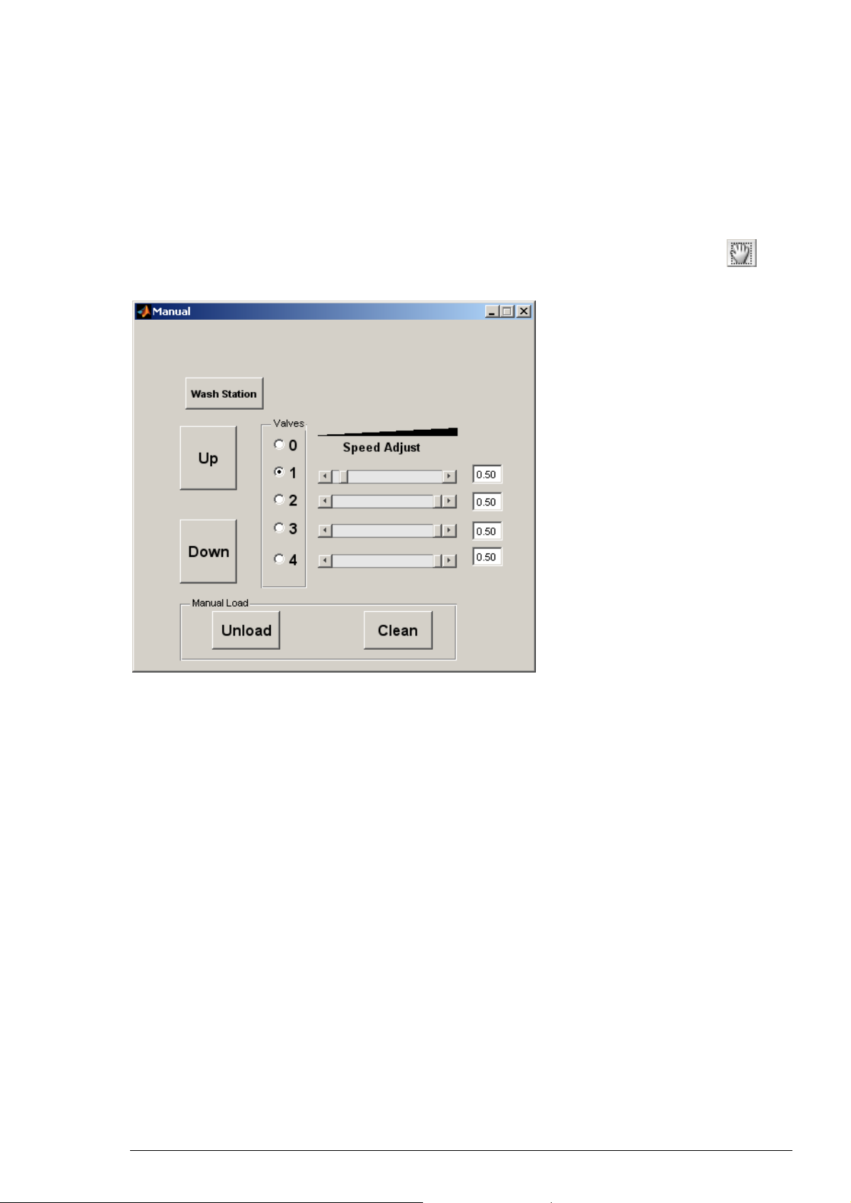
The Manual Window
The manual window is designed for the manual control of the solution, for placing the basket
into the washing station, for unloading the oocyte and for the cleaning of the basket. A single
click on the valve buttons switches on the desired pump. When all pumps are turned off, the
radio button for the value 0 is highlighted in blue.
The sliders and values on the right indicate the rotation speed of the inlet peristaltic pumps.
Note that the rotation speed of the outlet suction pump cannot be adjusted and keeps on
running at optimum as long as the HiClamp is switched on.
19
Page 26

HiClamp Manual
5.2 Electrode Alignment
Mounting and adjusting the electrodes
First, mount the provided glass capillaries on the measuring head. Use a binocular and adjust
the tip distance between 300 and 400 μm. Also be careful to align the tips to be at about the
same height. Then, fill the capillaries with either 3 M KCl or with a mixture from KCl and KAc
which reduces crystallization (1 M and 1.5 M, respectively). Filling should not exceed about
70 % of the capillary length.
Try to insert the filling needle or micro loader as close as possible to the tip region. Try to avoid
to have any air bubbles in the capillary after filling. The tip region usually fills by itself, because
the capillaries have a filament inside, but this takes sometimes a few minutes. Be patient and
wait until the tip region fills spontaneously. Tipping against the capillary in order to speed up
the process very often ends up in having many small air bubbles in the tip region making the
capillary unusable.
After filling, insert the provided AgAgCl wires. A small drop of mineral oil can be finally added
on the top of each electrode opening to prevent evaporation.
Please put the oil on top of each glass capillary after inserting the electrode wires! Otherwise
the AgAgCl coating will soak up the oil and destroy the electrical properties of the electrode.
Important: The recommended electrode resistance is in the range of 100 kilohms to 1 megaohm.
The electrode resistance also limits the maximum gain that may be used. It is considered a normal
behavior of electrodes that the resistance increases over time. It is recommended to use only
high-quality oocytes (with high membrane potential and low leak current) to avoid blockade
of the electrode tips. For an optimum clamp performance of the TEVC amplifier, the electrode
impedance should not exceed the recommended range.
Warning: Use only a well-chlorided silver wire for all electrodes. Use a diameter of 0.4 mm
if you plug the wire directly into the connectors of the vertical axis in order to avoid
damaging the vertical axis. We recommend the use of the provided connectors for
a better handling.
Once the measuring unit is installed on the HiClamp it is necessary to adjust the maximal depth
at which the electrodes will be moved during oocyte impalement. Please use the camera for
optical control of this alignment.
20
Page 27

TEVC Recording Protocol
Press on the Electrodes icon to open the Electrodes window.
Press on the "Down" button for slowly moving the electrodes down towards the oocyte basket.
Use the camera for optical control. Lower the electrodes progressively into the center of the
basket, just a little bit deeper than necessary to penetrate the oocyte. Note that the camera is
mounted on a rotating arm to facilitate the adjustments. If the electrodes are not centered use
the allen key (small hexagonal head screw) to move the position of the electrode holder base
plate.
If the electrodes are not correct aligned backward or forward use the icon Adjust Basket.
First move the basket in lateral and frontal direction by 30 units until the electrodes are in correct
position.
The adjustment is finished when the electrodes are lowered in the center of the basket in maximal
depth. This position of the electrodes is defined and saved when closing the window. Please use
the "Cancel" button to move the electrodes up and to restart the alignment procedure. Use
"Done" when you have found the right position. The position of the basket is stored in the file
BasketDefault.mat that is saved on your disk.
Important: Do not remove or edit the BasketDefault.mat file as this would destroy the calibration
parameters for the basket.
21
Page 28

HiClamp Manual
5.3 Test Model Cell
5.3.1 Testing the Amplifier with the Test Model Cell
Before you start to do real experiments with oocytes, we recommend to get familiar with the
HiClamp using the Test Model Cell (TMC). The TMC mimics the electrical (passive) properties
of a real oocyte impaled with microelectrodes (electrode resistance ~450 kOhm, membrane
resistance 100 kOhm, membrane capacitance ~ 200 nF)). Before you start, you have to connect
the TMC to the two electrode wire inputs (small connectors) and to the inputs where you would
connect the oocyte basket (larger connectors). The red plugs have to be connected on the left
side, respectively. When you now start the HiClamp and the HiClamp software, the amplifier
window opens in the basic mode in which you can test the electrode impedance by clicking
on the "R_Test" button.
Resistance values similar as shown above should be displayed with your TMC connected.
If you know activate the "Debug Mode" via the "Options" menu, the display changes
and you have access to all amplifier parameters. When you activate "Voltage Clamp"
the TMC will be clamped to 0 mV with a holding current of about 0 μA.
22
Page 29

5.3.2 Tuning the Amplifier
The build in digital amplifier can perform an automatic capacitance compensation in real-time
during the voltage-clamp recordings. This is an unique feature which is necessary to maintain
stable clamping during the movements of the oocyte basket. This automatic capacitance
compensation can be switched on and off with the "Auto On" check box.
Please note that "Auto On" should be checked during all recordings. Otherwise amplifier
oscillations could disturb your recordings or even damage the oocyte.
In order to get the highest stability the function of the automatic capacitance compensation
can be "tuned" although the default values should work under most circumstances.
For tuning switch off the "Auto On" first. You will notice that the displayed value in the
CX_CAP window will change immediately. The exact value depends now on many factors
like the amplifier, position of the TMC etc.
For tuning, change the Cx_Offs value until the CX_CAP window shows a value close
to 400. Now you can reactivate the "Auto On" again and your amplifier is tuned.
TEVC Recording Protocol
Please note that you right now performed tuning of the TMC. Repeat this tuning during your first
recording with a real oocyte, which is placed in the basket. The basket should be in the washing
station, impaled with electrodes, but clamp switched off. You do not have to repeat this tuning
for every oocyte or recording.
23
Page 30

HiClamp Manual
Now, after tuning, you can test the performance of your system with a simple “"Voltage Step
Protocol" (IV protocol) with, for example, 10 short voltage steps from -120 to +60 mV in 20 mV
increments.
24
Page 31

TEVC Recording Protocol
After executing and completing this voltage step protocol, the data display should show current
traces looking like this. Please see the picture below.
The traces shown above have been recorded with gain 1000 / 100 and an 1 kHz recording filter.
25
Page 32

HiClamp Manual
5.4 Selecting Oocytes for TEVC Recording
Selecting Oocytes
Please read chapter "Preparation of Oocytes" in Service and Maintenance.
Plating Oocytes
Please read chapter "Plating Oocytes" in Service and Maintenance.
Loading the oocytes plate
Place the 96 microtiter plate containing the oocytes in the right slot on the table.
Tighten the fixation of the plate (lower right) and verify that the holding screw is properly
secured. Poorly fixed oocyte plate can cause movement of the plate and result in a basket crash,
or other dysfunction of HiClamp.
5.5 Starting a Recording Sequence
A program sequence is a chronology of operations that are executed sequentially according to
a set of icons that are stored in the program sequence. Each icon symbolizes a fixed procedure,
for example loading the oocyte or setting up the amplifier. Please see chapter "Icons and
associated Effects" below. Each icon contains a given set of information to execute the desired
actions. For example, the "Oocyte" icon symbolizes the type of message injected into the oocytes,
the number of cells available etc. At difference, the icon corresponding to the amplifier will store
the information controlling the amplifier gain, filter conditions, voltage clamp set up, voltage
steps etc. To access the content of a given icon the user double click on the icon stored in the
program sequence. The first and simplest example presented below illustrates such procedure.
5.5.1 A first and simple example
The simplest example would be to test how oocytes are expressing membrane proteins and,
in the case of ligand gated channels, would consist at measuring the amplitude of the current
evoked by a brief pulse of agonist. To execute such operations it is necessary to first load an
oocyte into the recording basket, impale the electrodes, and apply the agonist while recording
the data.
The icons sequence above presents such a sequence. To prepare this sequence one icon at
a time is selected from the tools by a single click on the desired icon. Following the assembly
of such sequence it is now necessary to store in this HiClamp sequence the properties including
the type of message injected into the oocytes (mRNA or cDNA injected), the number and position
of the oocytes in the feeder plate, the solution that is applied and for how long, the holding
potential etc.
26
Page 33

TEVC Recording Protocol
Selections are done by a double click on the icon in the program sequence. A double click
on the first oocyte icon opens the “Load Plate” dialog. This window allows to enter parameters
about the well plate and about the type of DNA injected into the oocytes as well as the position
of this oocytes etc.
A double click on the second icon opens the “Test Well” dialog. This window allows
to select the recording conditions, data acquisition, filter and sampling settings,
drug application in the perfusion etc.
27
Page 34

HiClamp Manual
If you turn on the data acquisition by checking the box "Acquisition", the second icon will change
it´s appearance and "A/D" will be displayed instead of “W”.
If you click the button "Voltage Command" the respective dialog opens which allows you
to define voltage protocols in step and ramp mode.
Pushing the button Play will start HiClamp. The button “Play” will be replaced by Stop as soon as
the sequence is activated. Hitting the Stop button will stop the procedure. Importantly, however,
time should be allowed to complete the entire stop procedure before interacting with
the automate.
The window DataPlot will automatically pop out upon capture of your first data set. All data
are automatically stored on the hard disk in defined files (see file organization).
Before we get into more sophisticated protocol sequences, you should learn about the meaning
of all icons and the functions behind them.
28
Page 35

5.6 Icons and the associated Effects
Oocyte Loading
This icon is used to select the oocytes that will be taken for the measurements. So it is normally
the first of a program sequence. Oocytes setting, such as the injected message, number of cells,
date of injection etc. are stored in the corresponding data file. Access to these parameters is
done by a double click on the "Oocyte Loading" icon and filling the appropriate parameters.
All parameters are automatically stored in the data sequence that is stored in the experiment
folder. Multiple message types (cDNAs or mRNAs) can be defined in a single loading plate
allowing determination of multiple protein functions.
Compound Plate
This icon is used to define the assembly of compounds in the compound plate and the sequence
of events that will be measured. Parameters such as incubation time, holding voltage, compound
localization, concentrations etc. are defined by the user by a double click on the icon.
TEVC Recording Protocol
If you check the "Acquisition" box, options for setting sampling and filter frequency and the
"Voltage Command" button appears. Double click on "Define Solutions" opens another window
in which you can define and attribute solutions or compounds to the respective compound well
(A1 to H12). If you want to define a sequence of concentration starting for example at A1,
you just have to type the concentrations separated by a space.
29
Page 36

HiClamp Manual
After clicking on "Done" the list window appears. Once defined you can change the active
definition with the "Edit" function.
Wash/Test
The "Wash/Test" icon is used to move the oocyte into the wash station where compounds can be
washed or a test solution can applied to test the oocyte response. Parameters corresponding to
this step can be accessed after a double click on the icon. These parameters include the amplifier
settings, the voltage step control and drug application for the four available channels. The wash /
test command is often used to determine the leak current of the cell, and its response to
a standard solution. Note that measurements will be carried out only if the data acquisition mode
is turned on.
The "If" Step
The “if” icon is designed to set up a detection mode that can be used for testing a given condition
(holding current or response) of the cell. Typical example of the use of the “if” are shown in the
concentration activation curve example. The “if” applies on data that have been captured in the
last data acquisition epoch. For example, by the wash / test in the acquisition mode or A/D.
Parameters governing the “if” action are set up in the associated window that is accessible by
a double click on this icon in the program sequence. On the first double click, the cursor changes
mode from the arrow to a circle to indicate the need for a user action. The user should then point
to the icon where the program sequence should step back when the “if” conditions are not met.
30
Page 37

TEVC Recording Protocol
Following a double click on the desired icon the condition window is displayed.
“Go To Step” indicates the icon to which the “if” is returning when the condition are not met.
The “Leak” (expressed in μA) and current (expressed in μA) are used for the evaluation of the “if”.
Unless the cursor are set up (see below) values are determined on the 10 first data points for the
leak current and on the entire data epoch for the current. When the conditions are set a red line
is represented in the upper part of the sequence program to indicate how the sequence executes.
Equation is designed for future applications.
Loop with increment
The loop with increment causes the program sequence to loop back to the pointed icon and to
increment the position of the tested compound in the plate. For example, in the concentration
activation curve the loop with increment allows to measure successively the responses evoked
by a series of agonist concentrations. A double click on the loop icon changes the cursor from
arrow to circle, indicating that the user can now point to the icon where the loop should go back.
A double click on the desired icon turns on the corresponding window.
The current step indicates the icon position at which the loop was inserted. The loop to step
indicates the icon at which the loop is pointing and where the program sequence will step back
upon execution of the loop. The number of times indicates how many times the loop will be
executed. It is of good practice to always verify that this number corresponds to the desired
number of time of executions. This value can be manually changed to reflect the desired number
of time. When the button done is pushed this window automatically closes and a blue line is
represented under the program sequence to indicate how the loop will take place. The number
indicated in blue under the loop icon indicates the remaining number of passages. As error in
setting up the loop are easily made it is important to always double check before starting a given
sequence.
31
Page 38

HiClamp Manual
Loop no increment
The loop with no increment acts almost similarly to the loop. However, at difference with the loop
with increment, this loop causes no modification of the compound to be measured. This loop can
be used to measure a multiple number of time the same compound.
Another important difference between loop with increment and without increment is observed
in the loop associated window. In the loop without increment the user can set up a list of numbers
(lower editable panel) indicating the number of times the loop will be executed for each passages.
If the list contains less entry than the number of compounds the list will be repeated. In this
example the first compound will be measured four times, the second three times and the third
one time.
32
Page 39

TEVC Recording Protocol
Loop including a variable component
The loop including a variable element can be used for defining voltage step protocols. Whenever
you include the place holder "x" instead of a number, for example in the "Voltage Command"
window and you loop back to this definition, you can define in the appearing "LoopX" window
the values replacing the "x" incrementing with every loop count. In the shown example the
potential steps go from -100 mV to +20 mV in 20 mV increments. The holding potential between
the steps is -60 mV.
Next DNA
Adding this icon as the last step of a program sequence allows measurements on multiple
messages expressed in oocytes. A green line is automatically drawn indicating where the program
will loop back upon execution of this step.
End of the Sequence
This icon is normally placed at the end of the program sequence. Its execution causes the machine
to stop, close the perfusion and remove the last cell that was measured.
33
Page 40

HiClamp Manual
5.7 Data Acquisition Icons
Execution of the icons described above allows the control of HiClamp movement and action.
Additional icons are, however, necessary to perform data acquisition. Three icons control the
data acquisition and can be used in the program sequence. At the end of each data acquisition
the window DataPlot is turned on to display the last recorded data period.
Important: The timing of the data acquisition must be verified and the program should be set
to loop back before data acquisition is completed.
Starting Data Acquisition
This icon is typically used to start the data acquisition and to move the basket into the different
compounds as shown in the concentration activation curve example. Execution of this icon
initiates the data acquisition and sets up the voltage command and the amplifier conditions.
The execution of the program sequence continues independently from data acquisition.
Recording in the washing station
This icon indicates that the data acquisition mode has been set in the parameters of the wash /
test icon. Setting up the data acquisition causes the recording of a data epoch, the parameters
of which are set by the user. Execution of the program will resume only when the recording time
is completed and the automate will remain in the wash chamber for the entire duration set in the
corresponding parameters.
: Recording in Plate
Similarly to the wash / test icon, this icon is displayed only when the data acquisition mode is
turned on in the corresponding plate parameters. Execution of this icon will turn on the data
acquisition and maintain the program sequence at this step until completion of the recording
time. This mode is particularly useful to determine voltage dependent characteristics in a given
solution, for example in the determination of the properties of voltage dependent channels.
Super Icons and loading stored sequences
As particular program sequence may often be used in multiple experiments it is simpler to define
them as Super Icons. Super Icons can be designed by the user or used from a standard icon pool.
To set a Super Icon that will be represented in the upper part of HiClamp program it is sufficient
to save the currently defined sequence. Upon saving the program sequence HiClamp issues a
request window for setting up or not the Super Icon that can be chosen amongst *.jpeg files. To
activate a Super Icon it is sufficient to click once on the Super Icon and the program automatically
loads the program sequence. Note that all the fields concerning compounds will automatically be
emptied.
An alternative way of loading a stored sequence consists in opening a sequence previously saved
in a given experiment. Activation of the command “File -> Open” allows to browse through
previously saved sequences and the user can chose any sequence generated by HiClamp. Upon
loading a stored sequence a dialog windows open requesting if the parameters of the sequence
must be kept. Hitting the button “Yes” confirms that all the values, including the compound
names and concentrations will be kept in the newly defined sequence. Alternatively, answering
“No” will load the sequence but empty the compound names and concentrations previously
defined. Note that names, values and concentrations must be filed in before using the sequence.
34
Page 41

The Notebook
An electronic laboratory notebook is built in the HiClamp program. Access to this logbook is
automatic when the first sequence is activated. The notebook window cannot be turned off
during the experiment but can be minimized and recalled by a single click on the corresponding
icon. The notebook window is divided in two parts. The upper section presents the notes that
have been entered during the experiment. These notes are stored in the corresponding *.lab file
in the data folder (see data file structure below). Notes are entered in the lower section of the
window and can be modified as long as they are not entered or automatically stored by the
program. The time for the beginning and ending of the experiment is automatically generated
and stored in the logbook file. For security purposes the logbook is encoded and cannot be edited
with a text processing program. Attempts to edit the logbook should therefore be avoided as they
may destroy the file and your records.
5.7.1 Measuring multiple oocytes
TEVC Recording Protocol
Playing the simple example presented before measures the properties of the first oocyte and
stops. To take advantage of the HiClamp it would be important to be able to measure an entire
set of oocytes. This is readily possible by introducing a loop that will repeat the sequence as many
time as desired. Following the addition of the loop icon the sequence is now the following.
Note that the choice of the Loop with No Increment is indicated by the square arrow. Having
introduced the loop it is now necessary to indicate at which step the program should loop back.
This is readily done by a double click first on the loop icon and the action is indicated by a
change in the pointer from the arrow to a circle. A double click on the target step (in our
case the load plate icon) opens a control window in which the number of times the loop should
be executed is entered (for example 12 times to capture the response of an entire column of the
microtiter plate).
Following the entry (done) the program sequence displays the steps that will be executed with
a blue line in the lower part indicating how the loop will execute and at which steps it returns.
The number of times the loop will be executed is indicated by the number displayed below the
icon loop.
35
Page 42

HiClamp Manual
5.7.2 The concentration activation curve
A first example of a program sequence is the determination of the concentration activation curve
for a ligand gated channel. To establish such relationship the response of a cell exposed to a series
of ligand concentration is measured and the concentration activation curve is obtained by plotting
the peak of the evoked current (or, in some cases, the area under the curve) as a function of the
logarithm of the agonist concentration. A sequence typically used for these measurements
is illustrated in the next screenshot.
In step 1, the oocytes are automatically loaded from the loading plate (feeder). Oocytes
displaying a membrane potential less than -15 mV are automatically rejected. Following
a successful recording of the membrane potential the leak current is then determined in step 2
(10 s recording). Step 3 determines if the holding current satisfies the desired conditions (typically
less than -1 A). Step 4 and 5 are used to assess the cell response and cells displaying a response
superior to 200 nA are retained. The concentration activation curve is then measured between
steps 7 to 11. Note the red lines indicating the logical steps of the “if” whereas blue lines indicate
the logical steps of the loop. Note also the difference between the two loops (with and without
increment respectively). The sequence terminates once the desired number of cells is measured
(here 8) or the number of available oocytes is reached. The icon end indicates that the program
stops, unload the remaining oocyte and closes the perfusion.
The program sequence is established either by inserting the icons in the proper sequence,
by a single click on the icon tool bar, or by loading a predefined sequence. Loading of a
predefined sequence can be done either using menu File ”Open” to open a file sequence
or by a single click on a “Super Icon” displayed in the upper part of the window.
5.7.3 Recording Voltage-Gated Channel activity
Although analysis of ligand-gated and voltage-gated channels share significant similitude
experimental paradigm significantly differ. While in the case of ligand-gated channels
measurements generally start before moving the cell into the well containing the solution
of interest recordings of voltage gated channel activity can be quite different as we shall
illustrate in the next section.
The voltage protocols
Voltage protocols used for the activation, inactivation or characterization
of voltage-gated channels include single steps, multiple steps or ramps.
Voltage steps are programmed in the voltage command window. In the
simplest case, lets consider that the sequence comprises the following
elements:
36
Page 43

TEVC Recording Protocol
In the first step the oocyte is loaded, as previously described. The voltage protocol is defined
in the voltage command window that can be seen after opening the control of the step 2.
Opening the voltage command, by pressing the corresponding button, reveals the control
variables accessible for the definition of single or multiple voltage steps.
37
Page 44

HiClamp Manual
A single recording data epoch (or sweep) is defined by its holding voltage -100 mV,
and the number of steps the values of which are indicated in "LoopX" window.
The values above indicate which steps have to be sequentially performed. For example, to record
the activity of a potassium channel it would be necessary to step the voltage between different
values ranging from -50 to + 10 mV starting from a holding potential of -100 mV.
Activation of this voltage protocol would yield a sequence of seven voltage steps ranging from
-50 mV to + 10 mV by increment of 10 mV.
A typical example of currents recorded in a cell expressing a voltage gated potassium channel
in response to a series of voltage steps is shown.
As for ligand-gated channels, data are readily analyzed in DataMining using the cursors, and can
be expressed either as current in function of the voltage step or conductance. Results can be fitted
with Boltzman equation to describe the parameters best representing the channel properties.
Note the small tail current observed at the pulse offset. These data can be further analyzed using
multiple step controls with, for example, a constant activation pulse and a second step of variable
amplitude allowing the determination of the reversal potential. Such “tail current” protocols are
easily implemented using the voltage command window.
Note that the voltage command window also offers the possibility to apply repetitive steps at
regular time intervals.
38
Page 45

6 Data Analysis
As the HiClamp is intended to perform experiments in an unattended manner this means that
data captured by the robot should be self containing and easily identifiable. Typical experiments
will run for hours and often during day or night. Moreover, data concerning a particular set of
experiments may be captured in a single day or on several days and the data analysis software
must allow flexible analysis to be performed and regrouping of data coming from different
experiments.
Data analysis is performed using two complementary program called DataMining and
DataMerger. DataMining was designed for the analysis of a single experiment and to store
results in a form that is compatible for multiple analysis. DataMerger was designed to combine
experiments and prepare results for report presentation.
Before examining in more details DataMining and DataMerger programs it is, however,
of value to examine the data files created by HiClamp.
6.1 Data File Organization
A rapid look at the disk organization reveals that HiClamp creates folders that are organized
by year, month and day of experiment. Each HiClamp sets its own folders according to its
reference number set in the preference. HiClamp files include *.mat, *.seq, *.lab and *.vic.
Note: Do not erase any of these files otherwise data will be corrupted and reading will
be disrupted.
A given folder might contain one or more *.mat and *.seq files, each of them corresponding
to the activation of a play sequence. The *.mat contains the program sequence that was played
whereas the *.seq contains all the sequence of events that have been captured during the
particular experiment. The *.lab stores the laboratory notebook. Note that for laboratory safety,
this sequence is encoded and cannot be read into a text processor. The *.vic sequence stores all
the data that have been captured. Data are stored in a random access manner with each of the
data epoch having independent record length. Critical parameters such as voltage steps, setting
of the amplifier etc. are stored for each record and can be read during analysis.
39
Page 46

HiClamp Manual
6.2 DataMining
The DataMining was specially designed for the treatment of data captured with the HiClamp.
The aim of this program is to provide the user with a convenient interface allowing efficient
data retrieval and analysis. Upon activation of this program a window resembling the HiClamp
environment is displayed. The screenshot shows the main window of DataMining software.
DataMining window is divided in the tools for the upper panel, the program (middle panel)
and the sequence (lower panel). Selection the desired file to analyze is made by activating
the command Open in “File” menu. Selecting the desired sequence (*.seq) opens the sequence
that is displayed in the program panel (middle panel) and the screen might look as in the
following screenshot.
40
Page 47

Troubleshooting
The program sequence that is displayed in the middle panel is identical to the program sequence
used for the control of HiClamp. The lower panel illustrates the sequence of events that took
place during the data acquisition in a “chart paper like” recording. In this example you can see
that the HiClamp took three oocytes from the loading plate before finding one responsive cell
as indicated by the three oocyte loading icons that are seen in the initial section of the sequence.
Note that the sequence continues with the recordings (following the response in position 10,
record 166, indicated in blue). To scroll through the sequence, please use the toolbar placed
underneath the sequence.
DataMining takes full advantage of the icon-based concept allowing the user to efficiently
analyze data with a single click. The concept is that selection of an icon representing a data
acquisition module, such as steps 2, 4 or 7, in the example above, must trigger the analysis of data
that have been captured during the experiment and that correspond to this particular step of the
program sequence. Selection of the icon 4 should display all the oocytes that have been retained
as displaying appropriate leak current. A click on the icon 7 should display all the data that have
been captured for a given oocyte. Each oocyte is represented versus its position in the loading
plate. A typical display obtained by this action is illustrated in the screenshot below.
As the HiClamp system contains two plates with the oocyte loading plate and the compound
plate, two modes of representation can be envisaged. A first mode, illustrated below, consists in
representing data versus the position in the loading plate. Alternatively, data can be represented
versus the compound position. Switching between these two representation modes is obtained by
a click on the oocyte (or plate) symbol in the upper right panel. The mode of representation
corresponds to the icon displayed at the instant of the data selection.
Recordings obtains in a series of oocytes are represented versus their respective position
in the loading plate. The empty positions correspond to cells that didn’t meet the desired
criteria (resting potential, leak currents and agonist evoked current).
41
Page 48

HiClamp Manual
A single click on the lower left corner of any of these small graphs displays
the corresponding current traces as shown in the screenshot.
Another form of representation for the same data can be obtained by selecting the mode
Plot Seq. When this mode is selected data are represented as on a chart paper (see screenshot).
42
Page 49

6.2.1 Measuring the current amplitudes
Measurement of the peak ACh-evoked current is carried out automatically within boundaries
defined in the Set Cursor command. This command is activated by a single click on the button
presented in the right panel. Activation of the Set Cursor changes the display as follows.
Troubleshooting
Several cursor options are possible allowing measurements at the cyan and blue lines. Selection
“Cross Hair” returns the delta current between the two lines with the blue line at the minimum.
Min Max returns the delta current taking the minima and maxima between the two lines. –Min
returns the delta current between the value measured at the cyan position and the minimal value
measured up to the blue line. –Max returns the maximal delta current measuring the minimal
value at the cyan position and maximal between the two lines. –Min/First returns the minimal
value measured between the cyan (taken on the first measured curve) and blue line at the current
curve. Position of the minimal and maximal values determined for different curves can always be
visualized using the button. Positions will be represented on the data curves by a blue and red
circle.
43
Page 50

HiClamp Manual
Once cursors are set the ensemble of the data captured in a single run can be analyzed by
choosing the calculator mode and by a single click on the A/D after activation of the calculator
that is display in the right part of the commands.
Following the selection of the A/D the calculator should display the number 7, which corresponds
to the position of the A/D in the data acquisition program. Activation of the concentration
activation curve is performed by a click on the corresponding symbol (red curve). The successive
window allows the selection of the concentration of agonists that were tested in the experiment.
Following the selection of concentrations the graphs corresponding to the concentration
activation curves are automatically displayed.
In this graph the curves measured for each of the cell tested are represented as function of
the cell position in the loading plate. In this particular experiments five cells have been measured
during the sequence No. 3. Data can either be analyzed further within DataMining or saved for
later analysis with DataMerger. DataMerger is a companion program specially designed for the
analysis of results obtained in different experiments. A single click on the upper right icon saves
data for DataMerger. This will create a *.mat file that can later be open into DataMerger.
44
Page 51

6.2.2 The e-Labbook of the HiClamp
The electronic laboratory book that opens when HiClamp is set to run is displayed when
the sequence is read in DataMining. In this example the e-labbook is presented as follows:
Troubleshooting
Note that each sequence is indicated with the date, time of activation and end. A double click
on a selected sequence automatically opens this sequence in DataMining.
45
Page 52

HiClamp Manual
6.3 DataMerger
DataMerger program was especially conceived for the analysis of data selected with DataMining
and for combining experiments acquired in different session. Typically, experiments obtained on
day one might need to be compared with experiments from day two or analyzed simultaneously.
DataMerger allows analysis of single point measurements, multiple measurements, concentration
activation or inhibition curves, or voltage-dependent channel activity. Examples below are
illustrating the power of DataMerger for the data analysis and preparation of table and / or
data summary.
In the concentration activation curve illustrated in the DataMining example, curves were saved as
ACh.mat. These data can be read into DataMerger using the command Open in “File” menu and
choosing the file ACh.mat. The following window will appear.
Note that each concentration activation curve is represented by a corresponding graph. Curves
can then be traced either in isolation by a single click on the lower left corner of the graph or
individual traces can be retrieved by CTRL (right click). Activation of this command browse the
data file and retrieves the corresponding curve allowing constant visualization of the data quality.
Concentration activation curves can be traced one by one, by selecting each graph,
or all together by the option Plot All that will display the ensemble of curves.
46
Page 53

6.3.1 Statistic
Activation of the statistic button displays the average and SEM for the points that can be fitted
by a single or dual Hill equation. Note that each curve can be fitted separately and the mean of
curve can later be computed and analyzed. Values corresponding to the original data points and
normalized values are stored in an excel compatible format by activation of the excel icon.
For the single Hill equation and a concentration activation curve the equation used for
the curve fitting is in the form:
Troubleshooting
Y=1 / 1+( EC
/ x)^n
50
H
where: y = the fraction of evoked current, EC50 = concentration for 50 % activation,
nH = the apparent cooperativity, x = agonist concentration.
Dual concentration-activation curves are fit using the equation:
Y=a / 1+( EC
where: y = the fraction of evoked current, EC
/ x)^nHH +(1-a) / 1+( EC
50H
/ x)^nHL
50L
50H
= concentration for 50 % activation and
nHH = the apparent cooperativity of the high affinity component, a the fraction of high
affinity component, EC
= concentration for 50 % activation and nHL = the apparent
50L
cooperativity of the low affinity component , x = agonist concentration.
Concentration inhibition curves are fitted using comparable single or dual Hill equation with:
Y=1 / 1+( x/IC
50
)^n
H
where: y = the fraction of remaining current, IC50 = concentration for 50 % inhibition,
nH= the apparent cooperativity, x = antagonist concentration.
Dual concentration-inhibition curves are fitted using the equation:
Y=a / 1+( x/IC
where: y = the fraction of remaining current, IC
)^nHH +(1-a) / 1+( x/IC
50H
)^nHL
50L
= concentration for 50 % inhibition and
50H
nHH = the apparent cooperativity of the high affinity component, a the fraction of high
affinity component, IC
= concentration for 50 % inhibition and nHL = the apparent
50L
cooperativity of the low affinity component , x = antagonist concentration.
6.3.2 Example of a curve fitting
Examples of a curve fitting for the concentration activation using SIMPLEX.
Curve fitting of the data presented above can be effectuated in different mode. A first mode
consists in determining the best fit for each of the curve. This is done by selecting any one of
the curve (click on the desired data point).
47
Page 54

HiClamp Manual
When a curve is selected the corresponding data points are represented
as stars and the curve fitting parameters are displayed in the right window.
To optimize curve fitting it is often recommended to provide a first guess of the parameters.
In this example we shall select 100 M for the EC
.
50
48
Page 55

Troubleshooting
A continuous line corresponding to the guess parameters is displayed upon keying
the desired value and the display should appear as shown.
Pressing Fit Selected Data initiates the curve fitting procedure and result
with the best fit is displayed.
49
Page 56

HiClamp Manual
Values indicated in the windows correspond to the best fit obtained from the guess starting point.
Pressing Fit All Data initiates the curve fitting procedure on each of the curve and results in:
Pressing the Statistics button computes the standard error of mean and display the average
points together with the SEM.
50
Page 57

Selecting the average curve activates the display of an additional button
and computation of the Mean of Curves can be effectuated.
Troubleshooting
As in this example the mean of curves fits nicely the average curve no further adjustment
is necessary. Data can now be removed by selecting Delete Data in the menu.
Leaving only the average curve in the display. Data can be further processed and saved
as an excel data sheet for easy reporting by pressing the Excel button.
51
Page 58

HiClamp Manual
The corresponding Excel data sheet should be as following:
6.3.3 Example of curve fitting using “Global Fit”
An alternative to SIMPLEX curve fitting is to fit all the available data using the technique
of Global Fit. To activate the global fitting procedure it is first necessary to select the option
in the Computation menu bar.
52
Page 59

Troubleshooting
Once the selection of Global Fit is made a new option set is displayed allowing the selection
of single or dual Hill equation. In our example data points are readily fitted by a single Hill
equation and activation of the Global Fit yields the following results.
Result from the Global Fit are indicated in the new floating window and best fit obtained with
this method is illustrated by the continuous line. Note the similitude of results obtained with
the SIMPLEX curve fitting method. The check box (Max) allows to fix the maximal value to the
desired constant and new fitting can be initiated by pressing the Fit button.
As before results are readily obtained in the form of a spreadsheet by pressing the Excel button.
Results are displayed as follows:
Merging data from different experiments
Experiments may have been conducted on the same or different days in identical or different
conditions. DataMerger was designed to facilitate data analysis and to merge data sets.
For example, if two data sets have been collected and analyzed separately, data are easily
merged using the procedure:
53
Page 60

HiClamp Manual
Open DataMerger program.
Open the different *.mat produced with DataMining. Data will appear in DataMerger
and sorted according to the *.mat name.
To merge data press CTRL and click on the first data set. The pointer will
be changed from the arrow to a circle indicating that the merge is activated.
Maintaining the CTRL key, click on the panel you want to merge. The two panels
should change and results should be merged as follows:
Using the Option “Plot all” displays all the curve at once.
Note: If the curves have not the same number of points or not the same concentration, statistics
and curve fitting with Simplex will be restricted. Curve fitting can, however, be performed using
the global fit that now analyzes all the curves as a single ensemble.
54
Page 61

7 Examples
7.1 The voltage activation curve of Kv1.4
Two alternatives can be used for the measurement of the voltage activation curve by measuring
with the current activated during a voltage step and measuring of the relaxation current.
The program sequence for both example was the same and voltage steps were defined by setting
Step 1 to -50, 20 increments of 5 mV each. Setting Step 2 to -50 mV evoked a tail current of
sufficient amplitude for the measurement of the relaxation.
Troubleshooting
In the first case the current is measured during the voltage step and needs to be subtracted for
the passive properties of the cells. Recording performed in oocytes expressing the channel KV1.4
illustrate how a progressive depolarization of the membrane activates the potassium channel.
The screenshot shows the activation of KV1.4
55
Page 62

HiClamp Manual
Placing the crosshair (in the crosshair mode) immediately at the end of the capacitance discharge
and at the end of the voltage step allows a first estimation of the current activated by the voltage
step. Ideally, measurement of the current should be subtracted from the current passing through
the passive properties of the membrane which is usually obtained by subtracting the current
measured for the same voltage step in presence of a selective blocker.
Positioning the crosshair for KV1.4 activation
After setting the crosshair at the desired position the selection of the calculator is made and
the appropriate sequence step is selected by a single click. The number corresponding to the
step is displayed in the calculator window and results are readily obtained by selecting the
potassium IV button. The window displaying all the IV curves measured in different oocytes
is displayed and the desired IV can be displayed separately by selecting the appropriate graph.
The current-voltage window displaying the voltage activation curve is displayed.
Current-Voltage activation curve for KV1.4
A plot of the corresponding conductance can be obtained by pressing the button “conductance”
and setting the appropriate reversal potential for the considered ion (-80 mV in our example).
56
Page 63

Troubleshooting
Data can be fitted using the typical procedure of selecting the desired curve, selecting the
initial parameters, and activation of the curve fitting procedure. Data are fitted using a single
Boltzman equation. Note that results of the curve fitting are applied to the IV curve allowing
to compare the result of the fit with the data.
Plot of the conductance for KV1.4 and curve fitting
In the second case the current evoked by a voltage step is measured at the very beginning of
the relaxation curve. This second method offers the advantage of a direct measurement of the
current without requirement of the blockade by a selective inhibitor. Positioning of the crosshair
is adjusted after a blow up of the section of interest using the magnifying tool.
Positioning of the cursor on the relaxation tail
Note that the blue cursor is placed where the current is measured, the cyan (min value)
towards the end of the recording and the dark blue in the voltage window at the
position of the voltage step that activated the KV1.4 current and selection of Min-Max.
Results are obtained as described above for the activation steps and yielded comparable
activation profiles. The main advantage of this second procedure is to allow measurements
at a fixed potential and thereby alleviate the needs for the subtraction of traces in presence
of a blocker. This method is often used to characterize the voltage activation or blockade of
K-channels such as HERG channels. Measurement of the relaxation current at a fixed potential
is also often used for the characterization of blocking agents (Windisch et al., 2011).
57
Page 64

HiClamp Manual
Voltage activation measured on the relaxation of tail current
7.2 The voltage activation curve of NaV 1.5
To determine the voltage activation relationship for NaV 1.5 a standard series of voltage steps
are applied at periodic intervals. Voltage steps of regular increments can be set in the voltage
command interface either from Wash/Test, A/D or Plate with acquisition. Currents recorded in
response to a series of voltage steps in an oocyte expressing the NaV 1.5 are illustrated in the
screenshot below. The voltage protocol is illustrated in the lower traces. Automatic detection
of the peak inward current can be done using Min-Max setting with the cyan and blue crosshair
positioned as on the figure.
Voltage steps evoke inward currents in NaV 1.5:
Inward currents are analyzed using the “calculator mode” and selecting the appropriate icon
corresponding to the voltage step protocol. Display of the results is obtained by selecting the
icon indicating the typical IV curve of a sodium channel.
The representation of the loading plate with oocytes recorded for the given experiment setup
is represented and each single IV curve is shown as a “mini” graph as the following screenshot.
In this experiment a single oocyte was probed and the desired IV can be drawn by selecting the
“mini” graph represented on the left of the figure above.
58
Page 65

Troubleshooting
Plot of IV curves for the NaV 1.5
The plot of the conductance as a function the voltage step is readily obtained by activating
the conductance button. Note that the reversal potential is automatically proposed in the
Erev window, please see the next screenshots.
Conductance plot and reversal potential
Adjustment of the reversal potential deduced from the left screenshot result the graph presented
in the right screenshot. Importantly, conductance plot have large uncertainties for values close to
the reversal potential and meaningless points should be removed.
Removal of the desired sets of points is done by selecting delete points in the option window.
A dashed rectangle is drawn and adjusted with the mouse pointer encompassing the points that
must be removed.
Deleting an ensemble of points:
59
Page 66

HiClamp Manual
Curve fitting of the desired curve is done by selecting the curve of interest and with the Boltzman
equation. Following selection of the curve, done by a single click on any one of the corresponding
symbol, a window displaying the parameters of the Boltzman equation is displayed.
Curve fitting of the conductance with a Boltzman equation:
On the completion of the curve fitting results from the conductance fit are applied to the IV curve
to assess the quality of the fit on the current voltage relationship and yielding the plot illustrated
in the screenshot above. Note that multiple curves and statistic are treated equally using this
process.
Curve fitting of the IV curve for NaV 1.5
60
Page 67

8 Troubleshooting
8.1 Troubleshooting
Most problems occur seldom and only under specific circumstances. In most cases, it is only
a minor problem that can be easily avoided or solved.
If the problem persists, please contact your local retailer. The highly qualified staff will be glad
to help you. Please inform your local retailer as well, if other problems that are not mentioned
in this documentation occur, even if you have solved the problem on your own. This helps other
users, and it helps MCS to optimize the instrument and the documentation.
Please pay attention to the safety and service information (chapter "Important Safety Advice".
Multi Channel Systems has put all effort into making the product fully stable and reliable, but
like all high-performance products, it has to be handled with care.
Troubleshooting
61
Page 68

Page 69

9 Service and Maintenance
9.1 Service and Maintenance
Please make sure that you read this chapter thoroughly. Proper handling and cleaning of
the HiClamp will ensure reliable and long life time of the equipment. Most often, troubles
are simply due to mishandling. See also chapter "Troubleshooting".
9.1.1 Cleaning of the Basket
The basket is the most delicate part of HiClamp. Work on the basket only when absolutely
necessary and with great care! The following sequence is designed to allow cleaning of the
basket with a maximum of security.
1. Remove the electrodes as usual.
2. Lower the table (button down on the manual command).
3. Grab the basket holder on the side as shown on the picture.
4. Gently flush the basket with water without touching it.
5. Replace the basket in position.
Warning: If you noticed that the basket is not aligned or anything special,
you probably need to replace the basket.
9.1.2 Replacing or Realigning
If by accident the basket was damaged it is necessary to replace the basket. It is strongly
recommended not to attempt to repair the basket because both the wire position and
its shape are critical for the proper functioning of HiClamp.
As the basket is a critical part of HiClamp it was designed as an easily replaceable part
using the following procedure.
1. Remove the electrodes as usual.
2. Lower the table (button down on the manual command).
3. Grab the basket holder on the side as shown on the picture above
4. Replace with a the new basket
5. Align the basket if necessary.
63
Page 70

HiClamp Manual
6. Select the option Adjust Basket from the menu bar.
7. Select the basket position to Load Basket. The basket will move into the loading position and
the suction tube is lowered towards the basket. The suction tube will be used as the reference
point to which the basket needs to be aligned.
8. Use the two small Allen keys screws to bring the basket in the closest juxtaposition with
the suction tube but without contact.
9. Use the Backward or Forward button to align the basket to move the basket at the desired
position.
10. Press Done to close the CalibBasket window.
HiClamp is now ready for your next measurements.
64
Page 71

9.2 Preparation of Oocytes
Rough selection by filtration
1. Fill a 100 ml beaker with 80 ml of Barth's solution. Place the oocyte mesh sieve into the beaker
for grading the oocytes by size. The mesh of the sieve should be completely immersed in the
fluid.
2. Pipette an amount of oocytes onto the sieve. Approximately half the sieve should be covered
with oocytes. Too many oocytes on the filter will lead to an inefficient filtration.
3. Gently move the filter about two centimeters up and down (in the fluid) to separate the
oocytes by size.
4. Transfer the oocytes of appropriate size (that did not go through the sieve) into a 60 mm
Petri dish filled with Barth's + gentamicin.
5. The filtered oocytes are incubated at 18 °C for 1 h.
Note: The incubation step is necessary for identifying damaged oocytes in the next step.
Fine selection
Service and Maintenance
Use a stereo microscope and the golf-club shaped glass tool to check each single oocyte
for the following criteria.
Outer form:
No visible damage of the cell.
Well separated colors (dark and light brown).
No residues of follicular tissue.
Size:
Uniform size of about 1.2 mm.
Note: Selecting oocytes is an important step. Perform it very carefully to obtain best results.
65
Page 72

HiClamp Manual
9.3 Plating Oocytes
You need a well plate filled with Barth's + gentamicin ????
Important: Visually check all well plates before use. Use only unsterile and very flat plates.
Sterilization may lead to warped plates. Warped plates will decrease the injection and expression
efficiency.
1. Aspirate a number of oocytes from the dish with a transfer pipette by applying a low negative
pressure, for example, with a rubber ball.
2. Move from well to well with the transfer pipette, carefully dropping one oocyte into each of the
wells of the well plate. Grip only the glass pipette and do not squeeze the rubber ball, to avoid
that too many oocytes will leave the pipette. The oocyte should drop into the fluid by its weight
alone. If occasionally more than one cell drops into a well, this can be corrected after the plating
will have been finished.
3. Due to the higher density of the vegetal pole, the oocytes will usually settle with the animal pole
facing up if the (sticky) follicle cells were completely removed. Immediately check the position of
each oocyte under a stereo microscope, and correct it carefully with the golf-club shaped glass
tool, if the orientation is not correct. A manual correction should be necessary for less than five
percent of the oocytes if the follicle cells were completely removed.
4. Cover the well plate with its lid, and seal the rim with Parafilm to reduce evaporation, and store
it at 18 °C until injection. It is possible to inject the cells right after plating, but the oocytes should
not be further disturbed, for example not be washed or otherwise treated until they have been
allowed to adhere to the well bottoms (about 2 to 3 hours). The oocytes can also be injected on
the next day, after being stored overnight at 18 °C. If injected on the next day, it is recommended
to check the viability again under the microscope, and replace bad oocytes before the injection.
66
Page 73

10 TEVC Recording Background
10.1 TEVC Recording Background
About TEVC Recording with the HiClamp
The small-sized digital TEVC amplifier is integrated within the HiClamp and fully computercontrolled. It operates either in true current clamp or voltage clamp mode and uses a PI
(Proportional Integral) based technique. The ClampAmpC records up to ± 105 μA of current,
and the 16-bit A/D-conversion together with the over-sampling method results in an overall
resolution of 1 nA. The sampling frequency of up to 20 kHz guarantees high-performance data
acquisition of fast signals. The ClampAmpC features a short rise time of less than 500 μs, suitable
even for recording from fast sodium channels.
The recording sequences can be flexibly designed exactly to your requirements. Raw data can be
reviewed and evaluated offline with the HiClamp software, and also exported to custom analysis
software.
Preparations for Recording
Recording with the HiClamp is easy, but nevertheless, we recommend that you make
a few test recordings with non-injected oocytes and the provided sample recording protocol.
It is also a good idea run a test recording with the test model cell first.
Amplifier settings: Please make sure that the amplifier settings are appropriate for your ion
channel type. For more details, please see section "TEVC Recording - Background". For a first
test, the settings for slow ion channels are fine.
Ion channel kinetics Gain (P Coefficient) Integrator (I Coefficient)
slow 800 100 fast 2000 100
Glass micro electrodes: We recommend using a ready-made glass micro electrodes provided by
Multi Channel Systems, especially for new HiClamp users. You can use custom-built electrodes
as well, but you may observe problems if the design of electrodes does not follow the required
specifications. Please see "Ordering Information" for details.
Electrolyte solution for filling the glass electrodes of the measuring head. Recommended solutions
are 1.5 M KAc, 1 M KCl, pH 7.2 or 3 M KCl. The main disadvantage of a pure KCl solution is the
fast formation of salt crystals that will shorten the lifetime of the electrodes. The KAc/KCl solution
does not tend to crystallize, which is an advantage for storing the measuring head over night.
You may want to vary the KCl concentration of the KAc/KCl solution for optimizing your
experiments. We have used concentrations in a range from 0.1 M to 1 M KCl. Please keep in mind
that the electrode impedance increases with a decreased overall ion concentration in the
electrolyte.
Reusing a TEVC probe
Multi Channel Systems recommends replacing the recording electrodes each time when loading
a new oocyte well plate onto the HiClamp, for achieving best recording results. But in many cases,
a set of electrodes can be reused several times. It is also advisable to check the oocyte quality.
It seems that bad oocytes tend to clog the recording electrodes more easily than oocytes of
a very good quality.
To increase the lifetime of measuring heads, Multi Channel Systems recommends the following:
Use 1.5 M KAc, 1 M KCl, pH 7.2 as electrolyte for filling the electrodes to avoid crystallization,
which is a known issue with pure KCl solution.
Use only high-quality oocytes to avoid that membrane residues from non-viable oocytes clog
the electrode tips.
67
Page 74

HiClamp Manual
68
Page 75

11 Appendix
11.1 Technical Support
Please read the "Troubleshooting" part of the manual or help first. Most problems are caused
by minor handling errors. Contact your local retailer immediately if the cause of the trouble
remains unclear. Please understand that information on your hardware and software
configuration is necessary to analyze and finally solve the problem you encounter.
If you have any question or if any problem occurs that is not mentioned in this documentation,
please contact your local retailer. The highly qualified stuff will be glad to help you.
Please keep information on the following at hand
Description of the error (the error message text or any other useful information) and of the
context in which the error occurred. The more information on the actual situation you can
provide, the easier it is to track the problem.
The serial number of the device. You will find it at the rear side of the device.
The software and hardware version you are currently using. On the "Help" menu, click "About".
The displayed dialog box shows the version numbers.
Appendix
The operating system and service pack number on the connected computer.
The hardware configuration (microprocessor, frequency, main memory, hard disk) of the
connected computer. This information is especially important if you have modified the computer
or installed new hard- or software recently.
69
Page 76

HiClamp Manual
11.2 Technical Specifications
General information
Operating temperature 10 °C to 50 °C
Storage temperature 0 °C to 70 °C
Dimensions (W x D x H) 640 x 600 x 440 mm
Weight 47 kg
Power 230 VAC @ 50 Hz, 115 VAC @ 60 Hz
Amplifier
Type integrated TEVC amplifier
Operation Fully automatic and computer controlled
Reference electrodes Two independent active bath clamp
Maximal sampling rate 20 kHz
Data resolution 16 bit
Current electrode output
Output range - 105 μA to + 105 μA
Effective Current resolution 1 nA
Voltage range - 100 V to + 100 V
Voltage electrode input
Input range - 500 mV to + 500 mV
Voltage resolution 0.015 mV
Clamp voltage setpoint range - 500 mV to + 500 mV
Clamp voltage setpoint resolution 1 mV
Typical rise time in voltage clamp mode < 1 ms
Software
HiClamp software DataMining and DataMerger software
Connection to the computer USB 2.0 High Speed
Operating system: Microsoft Windows ® 7, Vista or XP
with NTFS, English version
70
Warning: The device may only be used together with software from Multi Channel
Systems MCS GmbH, and only for the specified purpose. Damage of the device and
even fatal injuries can result from improper use. Do not change hardware
configuration as it could lead to improper behavior of the system.
Page 77

11.3 About Preparation of Xenopus Oocytes
The materials and methods described in the following are kindly provided by the Bayer AG,
Leverkusen. The described procedures have been optimized over several years for best
performance of the oocytes and highest throughput. We recommend that you follow the
instructions for obtaining best results. Refer to standard protocols if you need more detailed
information on the subject.
Warning: Only qualified personnel should be allowed to perform laboratory work. Always
make sure you fulfill the requirements of local regulations and laws. Work according to good
laboratory practice to obtain best results and to minimize risks.
11.3.1 Materials
Recommended products are listed under “Sources of Supply” in chapter “Ordering
Information”.
Biological materials
Female frogs of Xenopus laevis.
Technical Equipment
Appendix
Shaker for the tubes (during defolliculation)
Stereo microscope for quality control of oocytes
8- / 12-channel pipette or Tecan Columbus Microplate Washer for filling the well plates
and washing the oocytes
96 well plates with conical bottom
It is very important that the well plates are produced carefully and have minimum variations.
Do not use coated plates, because oocytes will not adhere to the well bottom of coated plates!
Check each single plate before use. The plate should be even and it should not be distorted
in any way.
Note: If you use warped plates, you will encounter problems during injection. Check each plate
carefully before use.
Oocyte sieve for grading oocytes by size: Remove the bottom of a 50 ml Falcon tube.
Place a polyimide mesh with an 800 μm grid over the cut end and fix it with glue.
Oocyte transfer pipette: Cut and fire polished glass Pasteur pipette with an opening of ca.1.5 mm.
The cut end should be straight, that is, with a fixed diameter of about 1.5 mm, for at least 10 mm
so that a number of oocytes can line up inside the pipette as pearls on a string. See also chapter
“Plating Oocytes”.
Rubber ball for oocyte transfer pipette
Glass tool for moving oocytes: Glass Pasteur pipette, sealed over a Bunsen burner, and melted
into a golf-club like shape.
Petri or cell culture dishes, 100 mm
Petri dishes, 60 mm
Beaker, 100 ml
Razor blade
Forceps
Parafilm and standard laboratory equipment
71
Page 78

HiClamp Manual
11.3.2 Chemicals
Collagenase
For defolliculation:
Fresh 1.52 mg/ml collagenase in Barth’s solution without Calcium. The concentration has to be
optimized according to the collagenase batch and experimental conditions, see also chapter
"Defolliculation". Do not prepare solutions in advance as collagenase activity may decrease
rapidly even if the solution is stored at -20 °C.
Collagenase from Cl. histolyticum ca. 0.17 to 0.28 U/mg (according to Wünsch,1963) lyophilized.
Gentamicin
Stock solution: 50 μg/ml gentamicin (free base) in Barth’s solution. 1 ml aliquots with 50 mg/ml
gentamicin (free base) are stored at -20 °C.
Working solution: Dilute 1 ml of gentamicin stock in 1 l Barth's solution.
Gentamicin sulfate salt, potency approx. 600 μg Gentamicin per mg.
Alternatively to gentamicin, a mixture of penicillin and streptomycin can also be used to suppress
growth of microorganisms.
Barth’s solution
pH 7.4 (with NaOH)
88 mM NaCl
2.4 mM NaHCO
3
1 mM KCl
0.33 mM Ca(NO
0.41 mM CaCl
0.82 mM MgSO
)2 * 4 H2O
3
* 2 H2O
2
* 7 H2O
4
5 mM Tris/HCl
Barth’s solution without Ca
pH 7.4 (with NaOH)
88 mM NaCl
2.4 mM NaHCO
3
1 mM KCl
0.82 mM MgSO
* 7 H2O
4
5 mM Tris/HCl
2+
11.3.3 Oocyte Removal
1. Remove the appropriate amount of ovarian tissue surgically from one side of the frog.
Please refer to standard protocols on this subject (Stühmer and Parekh 1995).
2. Transfer the ovarian lobes into a new large Petri or cell culture dish (for example 100 mm
Falcon) filled with Barth’s without Ca
72
2+
.
Page 79

11.3.4 Collagenase Digestion and Defolliculation
Ovarian tissue contains immature and mature oocytes, as well as connective tissue from which
the oocytes must be separated. Ovarian tissue should be removed completely by collagenase
digestion. Oocytes are enveloped in a follicle cell layer which can cause trouble when plating
oocytes into well plates. Remaining pieces of follicular tissue causes oocytes to stick to the walls.
Oocytes will not move into correct positions in the middle of a well by themselves. Additionally,
the follicular cell layer sometimes hampers the impalement by the injection needle causing
damage to the oocytes or clogging of the tip. Therefore, it is important that isolated oocytes
are completely free of the surrounding follicular cell layer.
The whole procedure should be completed after about 2 to 2.5 hours. Please adjust the
collagenase concentration if this is not the case.
Appendix
1. Divide the tissue with a razor blade and a forceps into smaller, approximately 0.5 cm
2
large
pieces.
2. Transfer the clumps into 50 ml Falcon tubes containing 40 ml of 1.5 to 2.0 mg/ml collagenase in
Barth’s without Ca
2+
. A volume of up to 7.5 ml of tissue can be put into a single tube. For more
tissue, use additional tubes. Otherwise, the collagenase digestion would take too much time.
3. Place the tubes onto the shaker and let them shake gently at 20 °C. Check the progress after
90 min (and then every 15 min), and vigorously shake the tube briefly by hand to accelerate
the process.
4. Typically 120 minutes after beginning of the treatment, practically all oocytes should be
isolated and the majority of them should have already lost their follicular cell layer. If not,
continue the collagenase treatment for a maximum of 30 min.
5. Wash the oocytes extensively with Barth’s solution (minimum of 5 times with 30 ml) to remove
the collagenase completely.
6. Then fill up the tube (approx. to 45 ml) and put it back onto the shaker for 10 minutes.
7. Change the solution to Barth’s without Ca
2+
and put it onto the shaker again for another
10 minutes. Practically all oocytes should be defolliculated now. Shake the tube vigorously
to remove the follicle cells completely, if necessary.
8. Wash the oocytes with Barth’s solution until the supernatant is clear and free of follicular
cell layer fragments.
11.3.5 Selecting Good Oocytes
Rough selection by filtration
1. Fill a 100 ml beaker with 80 ml of Barth's solution. Place the oocyte mesh sieve into the beaker
for grading the oocytes by size. The mesh of the sieve should be completely immersed in the
fluid.
2. Pipette an amount of oocytes onto the sieve. Approximately half the sieve should be covered
with oocytes. Too many oocytes on the filter will lead to an inefficient filtration.
3. Gently move the filter about two centimeters up and down (in the fluid) to separate the
oocytes by size.
4. Transfer the oocytes of appropriate size (that did not go through the sieve) into a 60 mm
petri dish filled with Barth's + gentamicin.
5. The filtered oocytes are incubated at 18 °C for 1 h.
Note: The incubation step is necessary for identifying damaged oocytes in the next step.
73
Page 80

HiClamp Manual
Fine selection
Use a stereo microscope and the golf-club shaped glass tool to check each single oocyte
for the following criteria.
Outer form:
No visible damage of the cell.
Well separated colors (dark and light brown).
No residues of follicular tissue.
Size:
Uniform size of about 1.2 mm.
Note: Selecting oocytes is an important step. Perform it very carefully to obtain best results.
11.3.6 Plating Oocytes
You need a well plate filled with Barth's + gentamicin.
Important: Visually check all well plates before use. Use only unsterile and very flat plates.
Sterilization may lead to warped plates. Warped plates will decrease the injection and expression
efficiency.
1. Aspirate a number of oocytes with a transfer pipette by applying a low negative pressure,
for example, with a rubber ball.
2. Move from well to well with the transfer pipette, carefully dropping one oocyte into each
of the wells of the well plate. Grip only the glass pipette and do not squeeze the rubber ball,
to avoid that too many oocytes will leave the pipette. The oocyte should drop into the fluid
by its weight alone.
3. If occasionally more than one cell drops into a well, this can be corrected after the plating
will have been finished.
74
Page 81

11.4 Contact Information
Local retailer
Please see the list of official MCS distributors on the MCS web site.
User forum
The Multi Channel Systems User Forum provides the opportunity for you to exchange your
experience or thoughts with other users worldwide.
Mailing list
If you have subscribed to the Mailing List, you will be automatically informed about new software
releases, upcoming events, and other news on the product line. You can subscribe to the list on
the contact form of the MCS web site.
www.multichannelsystems.com
Appendix
75
 Loading...