

Page 1
ADPT-NN-16-STIM
16-Electrode NeuroNexus Probe
Adapter for MPA8I Amplifiers
with stimulation
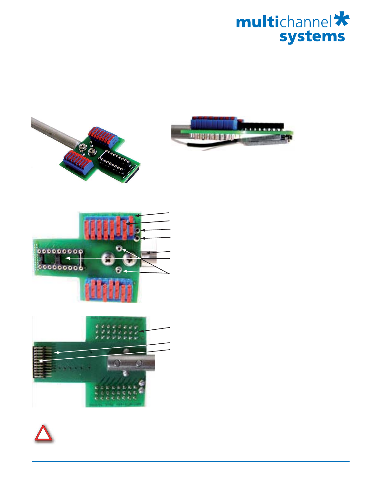
Connecting the MPA8I to the ADPT-NN-16-STIM
Top view : ADPT-NN-16-STIM
without NeuroNexus Probe
Top View
Side View
Connector for NeuroNexus Probe
MPA8I No. 1
MPA8I No. 2
Important:
Black side of MPA8I faced down !
Toggle Switch : Stimulation ON
Toggle Switch : Stimulation OFF
STIM
GND
NeuroNexus Probe Rod Mount NN-RM
Connector for 16-Electrode NeuroNexus Probe
GND
Bottom View
!
It is possible to stimulate one or more electrodes
by switching the toggle switches in ON position.
You can apply one type of stimulation pulse only!
Connector for STG (0.76 mm connector)
Connector for MPA8I No. 1
Connector for MPA8I No. 2
Warning: The device may only be used together with the MPA8I from Multi Channel Systems
MCS GmbH and the 16-channel probe from NeuroNexus, and only for the specified purpose.
Damage of the device and even fatal injuries can result from improper use.
Multi Channel Systems
MCS GmbH
Aspenhaustrasse 21
72770 Reutlingen
Germany
Fon +49-7121-9 09 25Fax
+49-7121-9 09 25-11
info@multichannelsystems.com
www.multichannelsystems.com
0
© 2012 Multi Channel Systems MCS GmbH
Product information is subject to change
without notice.
Page 2
ADPT-NN-16-STIM
16-Electrode NeuroNexus Probe
Adapter for MPA8I Amplifiers
with stimulation
Connecting the NeuroNexus Probe to the ADPT-NN-16-STIM
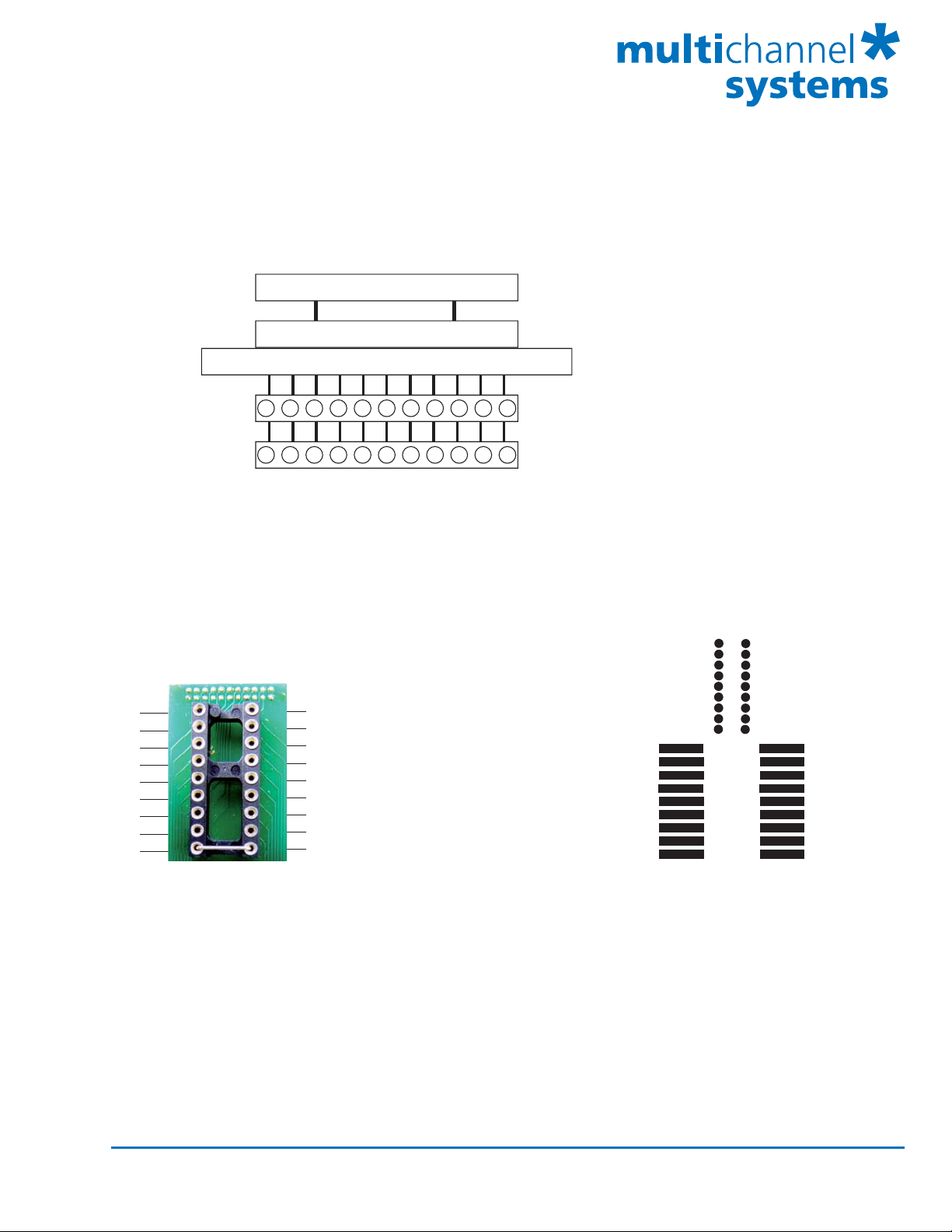
Channel assignment, output pins (connected to the MPA8I)
NeuroNexus Probe
NN-ADAPTER
MPA8I No. 1
MPA8I No. 2
G
G
87654321R
G
87654321R
G
Shown are the output pins of the adapter that are connected to the miniature preamplifiers MPAI when
looking directly at the pins. The labelled channels are the ground channels (G), the reference channel (R),
and the 8 recording channels (1 to 8) of the MPA8I. Please see the MPA8I Manual for details.
Note: Operation of the MPA8I is differential. The reference channel R has to be used
for obtaining a proper signal.
Channel assignment, input pins (connected to NeuroNexus Probe)
MPA8I MPA8I
No. 2
1
2
3
4
5
6
7
8
R
No. 1
8
7
6
5
4
3
2
1
G
MPA8I
No. 2
9
10
11
12
13
14
15
16
R
MPA8I
No. 1
8
7
6
5
4
3
2
1
G
Shown are on the left side the input pins of the adapter that are connected to the NeuroNexus probe.
The labelled channels are the ground channel (G), the reference channel (R), and the eight recording
channels (1 to 8) of the MPA8I. Please see the MPA8I Manual for details. G and R have been connected
together as factory-default settings. You can change this connection to meet your requirements.
On the right side you see the input pins connected to the NeuroNexus probe, and the correlating toggle
switches for stimulating one or more electrodes.
Pin Layout for MC_Rack: MPA8I No. 1 MC_Rack
Pin 1 - 8 Channel 1 - 8
MPA8I No.2
Pin 1 - 8 Channel 9 - 16
Multi Channel Systems
MCS GmbH
Aspenhaustrasse 21
72770 Reutlingen
Germany
Fon +49-7121-9 09 25Fax
+49-7121-9 09 25-11
info@multichannelsystems.com
www.multichannelsystems.com
0
© 2012 Multi Channel Systems MCS GmbH
Product information is subject to change
without notice.
 Loading...