

Page 1
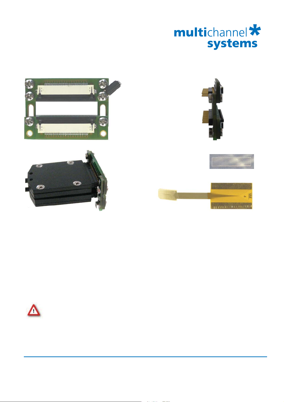
ADPT-FM-72
FlexMEA adapter
for connecting two MPA32Is to the FlexMEA72
GND
Connector for FlexMEA72
Connector for FlexMEA72
Connector
ADPT-FM-72
Connector
for MPA32I
No. 2
Connector
for MPA32I
No. 1
Connectors
for
FlexMEA72
Plastic Spacer
Adapter ADPT-FM-72 connected to both MPA32Is.
FlexMEA72
ADPT-FM-72: The adapter is equipped with the connectors for the MPA32Is on one side and the connectors
for the FlexMEA72 on the other side.
MPA32I: The side with no screws is considered to be the top side of the MPA32I. The MPA32Is have to be
connected with their top sides facing to each other (to the inner part of the adapter) and the bottom sides
facing outwards.
FlexMEA72: On the FlexMEA72 the side with the writing “NMI” is the side with contact pads and electrodes.
This side is optically golden shimmery and the letters “NMI” are readable.
Plastic Spacer: The spacer between FlexMEA72 and drawers ensures the contact from the printed circuit
board of the adapter and the contact pads.
Warning: The adapter ADPT-FM-72 may only be used together with a FlexMEA72 and
with MPA32I from Multi Channel Systems MCS GmbH, and only for the specific purpose.
Damage of the device and even injuries can result from improper use.
Scope of delivery:
1 FlexMEA72 adapter ADPT-FM-72
6 Button head srews M2x5 mm, washers, screw nuts
2 Bars
Multi Channel Systems
MCS GmbH
Aspenhaustrasse 21
72770 Reutlingen
Germany
Fon +49-7121-9 09 25Fax
+49-7121-9 09 25-11
info@multichannelsystems.com
www.multichannelsystems.com
0
© 2012 Multi Channel Systems MCS GmbH
Product information is subject to change without
notice.
Page 2
ADPT-FM-72
FlexMEA adapter
for connecting two MPA32Is to the FlexMEA72
Please follow the instructions for mounting the the FlexMEA72 on the ADPT-FM-72 and the
MPA32Is step by step.
Necessary tools: A small Philipps head screwdriver
a sharp forceps
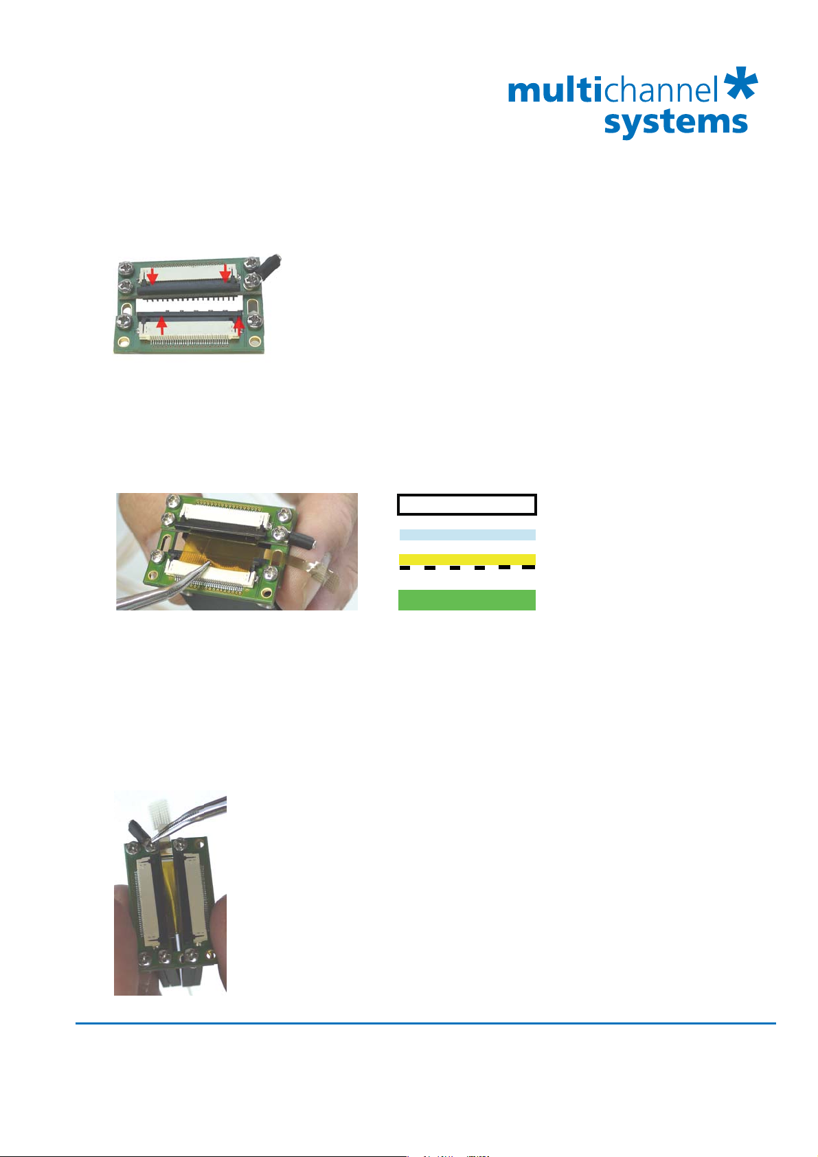
1. Please loosen the screws of the adapter that it is possible to move the bars of the ADPT-FM-72.
2. Open the withe drawers of the adapter by pre-drawing the black parts of the drawers
with the help of a forceps.
3. Connect the MPA32Is in correct manner, the bottom sides with screws must face outwards.
Drawer
Spacer
Contact pads of FlexMEA
Adapter with PBC
4. Insert the contact pads of the FlexMEA72 carefully with a forceps into the first drawer.
Insert the FlexMEA72 upside down, because the contact pads must have contact to the
printed circuit board of the ADPT-FM-72. Place the plastic spacer between contact pads
and drawer for a good contact between PCB and FlexMEA72. Please see the scheme.
The electrode part of the FlexMEA should face in direction of the ground connector.
Please handle the FlexMEA72 with great care!
5. Close the first drawer by pushing back the black part into the white part. The contact pad is fixed.
6. Insert the opposite contact pad of the FlexMEA72 into the second drawer,
place the plastic spacer between the back side of the FlexMEA and the
drawer and close it.
7. Thighten the screws of the ADPT-FM-72.
When connecting the FlexMEA72 and the adapter as shown on the picutre,
:
the electrodes of the FlexMEA72 face in the same direction as the MPA32Is.
The MPA32I on the right side is considered to be MPA32I No 1 with channels
No 1 to 32. The MPA32I on the left side of the FlexMEA is defined to be
MPA32I No 2 with channels 33 to 64.
Multi Channel Systems
MCS GmbH
Aspenhaustrasse 21
72770 Reutlingen
Germany
Fon +49-7121-9 09 25Fax
+49-7121-9 09 25-11
info@multichannelsystems.com
www.multichannelsystems.com
0
© 2012 Multi Channel Systems MCS GmbH
Product information is subject to change without
notice.
Page 3

FlexMEA72
Flexible Microelectrode Array with 72 electrodes for use via ADPT-FM-72 adapter with
two 32-Channel Miniature Preamplifier MPA32I for in vivo and in vitro applications.
Technical Specifications FlexMEA72
Temperature compatibility 10 - 40 °C
Dimension (W x D) of the FlexMEA72 42 mm x 12 mm
Thickness of the electrode field 12 m
Weight < 1 g
Base material Polyimide 2611 foil
Contact pads and track material Gold
Electrode diameter 100 m
Interelectrode distance (centre to centre) 625 to 750 m
Perforation Diameters of the holes 100 m
Electrode height Planar
Electrode type TiN electrodes (Titanium nitride)
Isolation type Polyimide 2611 foil
Electrode impedance Approximately 50 k
Electrode layout grid 9 x 8
Number of recording electrodes 64
Number of reference electrodes 4 internal reference electrodes
Number of ground electrodes 4
MC_Rack Version 4.1.1 and higher
Data Source Setup Source Layout: Configuration, Total Number of Channels: 64,
Amplifier: FA64I/S, MEA: FlexMEA72.
Channel map Display: Tab Layout > Default Map (FlexMEA72.cmp).
Cleaning Rinse with distilled water, optional with ethanol 70%.
Do not autoclave or sterilize FlexMEAs by heat. These MEA types are not heat-stable
and will be irreversibly damaged! Please do not use an ultrasonic bath for cleaning.
Multi Channel Systems
MCS GmbH
Aspenhaustrasse 21
72770 Reutlingen
Germany
Fon +49-7121-9 09 25Fax
+49-7121-9 09 25-11
info@multichannelsystems.com
www.multichannelsystems.com
0
© 2012 Multi Channel Systems MCS GmbH
Product information is subject to change
without notice.
Page 4

FlexMEA72
625 μm
39
26
48
17
57
GND
GND
8
17
26
A1 A2 A3 A6 A7 A8
REF
38
27
47
18
56
REF
REF
9
18
27
B1 B2 B3 B6 B7 B8
28
37
46
55
64
1
10
19
28
C1 C2 C3 C4 C5 C6 C7 C8
36
45
54
63
2
11
20
29
D1 D2 D3 D4 D5 D6 D7 D8
35
44
53
62
3
12
21
30
E1 E2 E3 E4 E5 E6 E7 E8
34
43
52
58
7
13
22
31
F1 F2 F3 F4 F5 F6 F7 F8
4233
49
659
16
23
32
G1 G2 G3 G4 G5 G6 G7 G8
REF REF
40
50
60
5
15
25
H2 H3 H4 H5 H6 H7
GND GND
41
51
61
4
14
24
750 μm
Electrode field
Direction to contact pads
100 μm
J2 J3 J4 J5 J6 J7
MPA32I Channel 33 - 64 MPA32I Channel 1 - 32
The numbers in the electrodes are the recording channel numbers that refer to the channel numbers
in the MC_Rack program. Please make sure that you have selected “Configuration” in the “Channel Layout”
under “Data Source Setup” with a total number of 64 channels. Deselect the check box “Digital input channel”
if you do not need it, otherwise one recording channel is missing! In “Amplifier”, please choose
FA64I/S and in “MEA” FlexMEA72. In Layout tab of the display, please click ”Default Map”.
The letter digit code below is the electrode identifier and refers to the position of the electrode in the grid.
Note: The MC_Rack channel map is constructed by looking on the back side of the electrodes!
Please make sure to connect the left hand side of the FlexMEA72 contact pads (electrode side on top)
via ADPT-FM-72 adapter to the first MPA32I (channels 33 to 64), and the right hand side to the second
MPA32I (channels 1 to 32). Read the SC2x32 data sheet when using a signal collector.
The electrodes are on the same side as the contact pads. The side with the writing “NMI” is the side with
the contact pads and electrodes. It might be a bit confusing that the pads look “stronger” from the wrong
side, but if you hold the FlexMEA72 into the light, you see that the contact pads have a three-dimensional
appearance only from the correct side.
Multi Channel Systems
MCS GmbH
Aspenhaustrasse 21
72770 Reutlingen
Germany
Fon +49-7121-9 09 25Fax
+49-7121-9 09 25-11
info@multichannelsystems.com
www.multichannelsystems.com
0
© 2012 Multi Channel Systems MCS GmbH
Product information is subject to change
without notice.
 Loading...