

Page 1
Standard 60MEA
60MEA200/10iR-ITO, 60MEA200/30iR-ITO,
60MEA100/10iR-ITO, 60MEA100/10-ITO,
60MEA100/10iR-Ti, 60MEA200/30-Ti,
60MEA200/10iR-Ti, 60MEA200/30iR-Ti
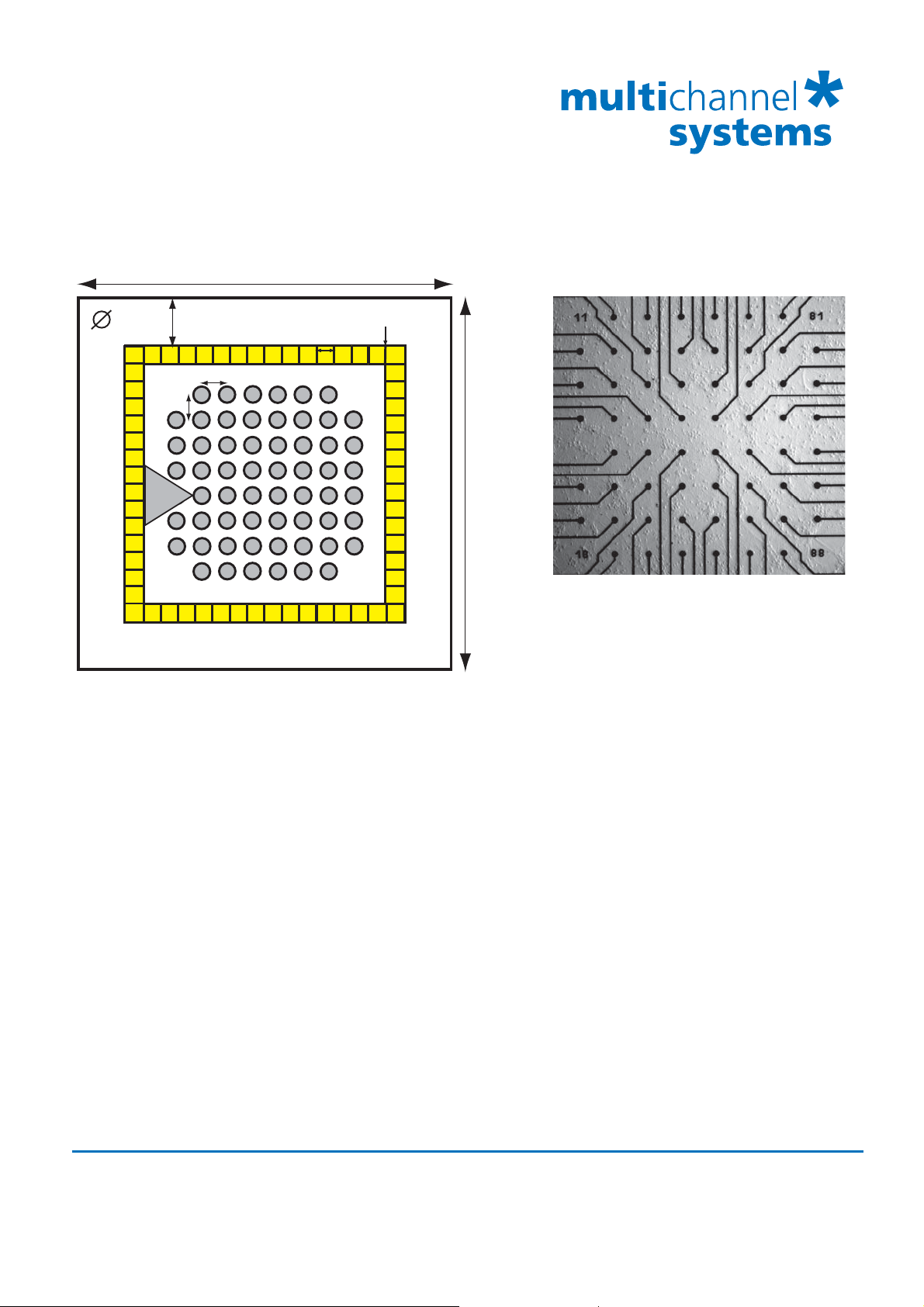
49.0 mm
0.2 mm
10 / 30 μm
5.4 mm
2.2 mm
200 / 100 μm
41
42
43
44
45
46
47
48
51 61 71
62
52
53
63
64
54
55
65
56
66
57
67
58
68
72
73
74
75
76
77
78
82
83
84
85
86
87
49.0 mm
REF
12
13
14
15
16
17
21 31
32
22
33
23
24
34
25
35
26
36
27
37
28
38
Standard electrode layout grid 8 x 8
Contact pads
Technical Specifications Standard 60MEA
Temperature compatibility 0 - 125 °C
Dimension (W x D x H) 49 mm x 49 mm x 1 mm
Base material Glass
Track material ITO (Indium tin oxide) or Ti (Titanium)
Contact pads ITO (Indium tin oxide) or TiN (Titanium nitride)
Electrode diameter 10 or 30 μm
Interelectrode distance (centre to centre) 100 or 200 μm
Electrode height Planar
Electrode type TiN (Titanium nitride)
Isolation type Silicon nitride 500 nm (PEVCD)
Electrode impedance 30 - 50 k for 30 μm electrodes, 250 - 400 k for 10 μm electrodes
Electrode layout grid 8 x 8
Number of recording electrodes 59 (with iR) or 60 (without iR)
Number of reference electrodes 1 internal reference electrode (iR) or without internal reference
MC_Rack
Source layout in “Data Source Setup” 2 dim. (MEA) or Configuration
Channel map Default
MEA perfusion chamber (w/o) Without ring
(gr) Glass ring: ID +/- 19 mm, OD 24 mm, height 6 / 12 mm
(pr) Plastic ring without thread: ID 26.5 mm, OD 30 mm, height 6 / 3 mm
(pr-T) Plastic ring with thread: ID 26 mm, OD 30 mm, height 6 / 15 mm
Multi Channel Systems
MCS GmbH
Aspenhaustrasse 21
72770 Reutlingen
Germany
Fon +49-7121-9 09 25Fax
+49-7121-9 09 25-11
info@multichannelsystems.com
www.multichannelsystems.com
0
© 2014 Multi Channel Systems MCS GmbH
Product information is subject to change
without notice.
Page 2
Standard 60MEA
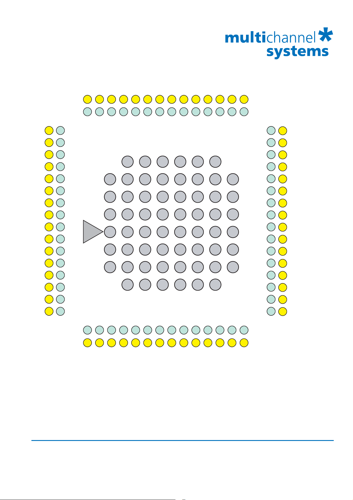
Standard electrode layout grid 8 x 8
MEA pins, 1 dim.
MEA pins, 2 dim.
Electrode #
23 33 33
22 22 22
21 12 12
20 23 23
19 13 13
18 34 34
17 24 24
16 14 14
15 15 REF
14 25 25
13 35 35
12 16 16
11 26 26
10 17 17
24 25 26 27 28 29 30 31 32 33 34 35 36 37
21 32 31 44 43 41 42 52 51 53 54 61 62 71
21 32 31 44 43 41 42 52 51 53 54 61 62 71
21 4131 51 7161
REF
12
13
14
15
16
17
22
23
24
25
26
27
32
33
34
35
36
37
42
43
44
45
46
47
52
53
54
55
56
57
62
63
64
65
66
67
72
73
74
75
76
77
82
83
84
85
86
87
28 4838 58 7868
Electrode #
MEA pins, 2 dim.
63 63 38
72 72 39
82 82 40
73 73 41
83 83 42
64 64 43
74 74 44
84 84 45
85 85 46
75 75 47
65 65 48
86 86 49
76 76 50
87 87 51
MEA pins, 1 dim.
9 27 27
8 36 36
Electrode #
MEA pins, 2 dim.
MEA pins, 1 dim.
28 37 38 45 46 48 47 57 58 56 55 68 67 78
28 37 38 45 46 48 47 57 58 56 55 68 67 78
7 6 5 4 3 2 1 60 59 58 57 56 55 54
77 77 52
66 66 53
Electrode #
MEA pins, 2 dim.
MEA pins, 1 dim.
The numbering of MEA electrodes in the 8 x 8 grid follows the standard numbering scheme for square grids:
The first digit is the column number, and the second digit is the row number. For example, electrode 23 is
positioned in the third row of the second column.
The specified MEA pin numbers (1 dim. or 2 dim.) are the channel numbers that are used in the data
acquisition program, when using the 1 dimensional layout or the 2 dimensional layout (or Configuration)
in the “Data Source Setup”. The electrode 15 is missing in MEAs with internal reference electrode.
It is replaced by a big internal reference electrode, connected to pin 15 of the amplifier.
Multi Channel Systems
MCS GmbH
Aspenhaustrasse 21
72770 Reutlingen
Germany
Fon +49-7121-9 09 25Fax
+49-7121-9 09 25-11
info@multichannelsystems.com
www.multichannelsystems.com
0
© 2014 Multi Channel Systems MCS GmbH
Product information is subject to change
without notice.
 Loading...