

Page 1
60-6wellMEA
GND
GND
GND
GND
GND
GND
32
21
33
44
43
42
41
53
54
61
62
63
72
82
83
73
64
74
84
85
75
65
86
76
87
77
66
78
67
68
55
56
58
57
47
48
46
45
38
37
28
36
27
17
26
16
35
25
15
14
24
34
13
23
12
22
A2
A3
A4
A6
A8
A9
B1
B2
B3
B4
B5
B6
B7
B8
B9
D1
D2
D3
D4
D5
D6
D7
D8
D9
C1
C2
C3
C4
C5
C6
C7
C8
C9
E1
E2
E3
E4
E5
E6
E7
E8
E9
F1
F2
F3
F4
F5
F6
F7
F8
F9
A7
A8
A9
A4
A5
A6
A1
A2
A3
B7
B4
B1
B8
B2
B5
B3
B6
B9
C7
C4
C1
C8
C2
C5
C3
C6
C9
D7
D4
D1
D8
D2
D5
D3
D6
D9
E7
E4
E1
E8
E2
E5
E3
E6
E9
F7
F4
F1
F8
F2
F5
F3
F6
F9
33
A1
Electrode Layout
22
12
23
13
34
24
14
15
25
35
16
26
17
27
A1
33
33
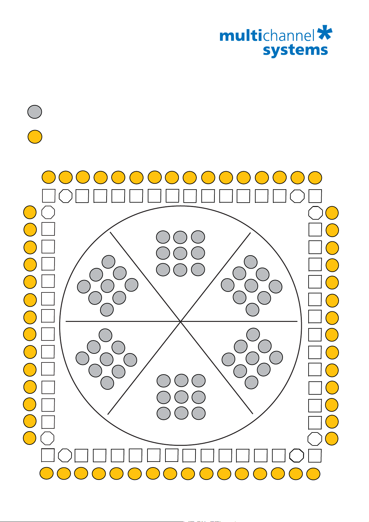
The letter-digit code is the electrode identifier and refers to the position of the electrode
in the 60-6wellMEA.
The specified amplifier pin numbers are the MEA-System channel numbers that are used
in the data acquisition program. The pin numbers 32, 61, 84, 67, 38, and 15 are grounded.
33
F6
21
F9
32
GND
313144
A4
A7
43
A1
41
A8
42
5252515153
A2
A5
A3
A6
54
A9
GND
61
62
B7
F3
F5
F2
F8
F1
F4
F7
MCS
F1
F2
F4
F3
F5
F7
F6
F8
A1A1A2
A4
A7A7A8
F9
F
A3
A5A5A6
A9
A
B1
B4
B7
B8
B
B5
B9
B2
B3
B6
C7
GND
E9
E6
E3
E5
E3
E6
E2
E9
E5
E1
E8
E4
E7
E
D
D8
D9
D6
D5
D2
D3
C
D7
D4
D1
C9
C8
C6
C5
C3
C4
C1
C2
E2
E8
E1
E4
E7
GND
D9
D6
D3
D5
D2
D8
D1
D4
D7
GND
717163
B4
GND
C9
B1
B8
B2
B5
B3
B6
B9
C7
C4
C1
C8
C2
C5
C3
C6
72
82
73
83
64
74
84
85
75
65
86
76
87
77
36
28
37
38
45
46
48
47
57
58
56
55
68
67
78
66
© 2013 Multi Channel Systems MCS GmbH
Page 2
60-6wellMEA
31
44
43
42
41
52
51
53
54
A 1
A 2
A 3
A 4
A 5
A 6
A 7
A 8
A 9
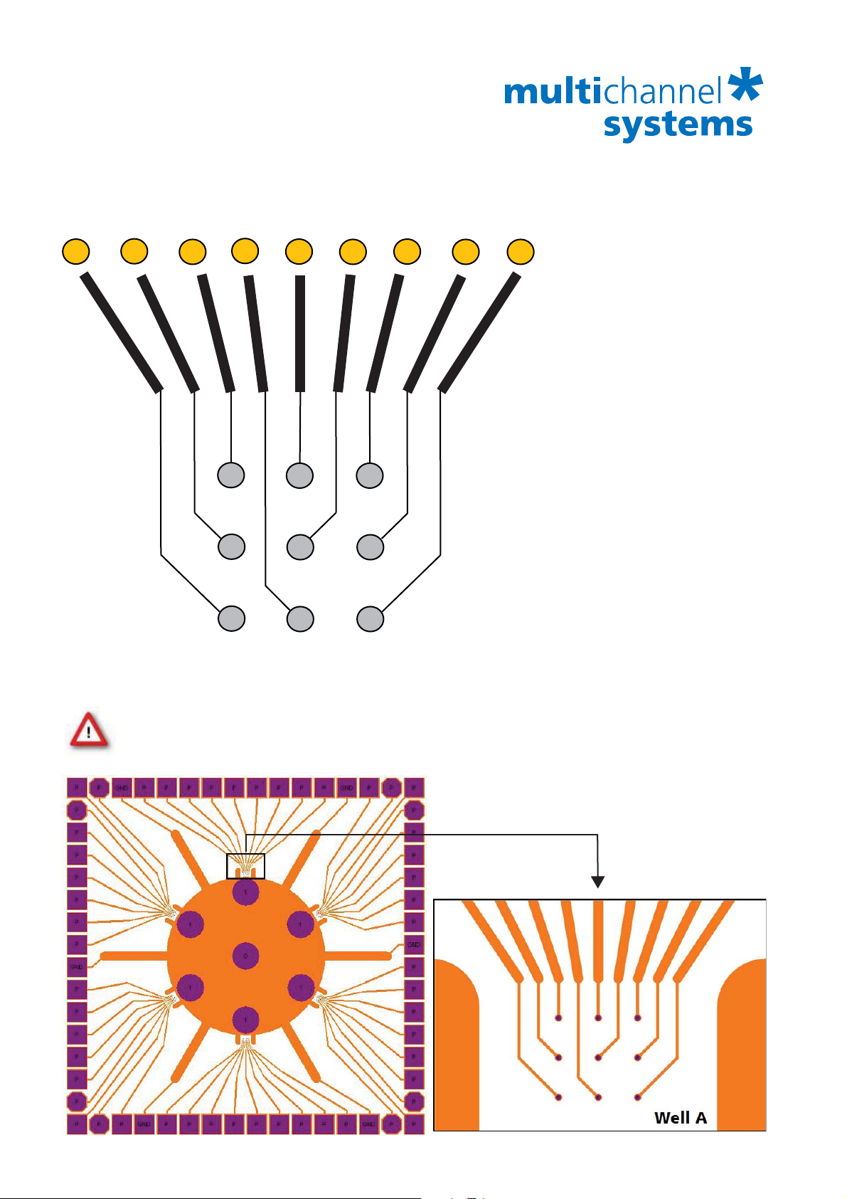
Electrode layout inside each well Example: Well A
31
44
Electrode identifier code refering to the position
in the 60-6wellMEA.
43
A 1
A 4
A 7
41
42
A 2
A 5
A 8
52
A 3
A 6
A 9
51
53
54
MEA amplifier pin numbers
Overwiev:
MEA amplifier pin numbers (digit)
and correspondent electrode identifier
code (letter-digit) inside each well.
A B C D E F
1 43 63 65 56 36 34
2 42 82 76 57 17 23
3 51 83 77 48 16 22
4 44 71 75 55 28 24
5 52 73 87 47 26 12
6 53 64 66 46 35 33
7 31 62 85 68 37 14
8 41 72 86 58 27 13
9 54 74 78 45 25 21
GND 32 61 84 67 38 15
Important: Please insert the 60-6wellMEA into the MEA amplifier with the writing on the
MEA chip (in this example MCS) on the left side viewed from the front, with the sockets
of the MEA1060 amplifier or the articulation of the MEA2100 headstage in the back.
Well A
Well BWell F
MCS
Well E
Well C
Well D
© 2013 Multi Channel Systems MCS GmbH
Page 3
60-6wellMEA
A2
A3
A4
A6
A8
A9
B1
B2
B3
B4
B5
B6
B7
B8
B9
D1
D2
D3
D4
D5D6D6
D7
D8
D9
C1
C2
C3
C4
C5
C6
C7
C8
C9
E1
E2
E3
E4
E5
E6
E7
E8
E9
F1
F2
F3
F4
F5
F6
F7
F8
F9
Electrode Layout
Channel Map
F1
MCS
E3
F4
F2
E6
E2
F3
F5
F7
E9
E5
E1
F6
F8
E8
E4
F9
E7
F
E
A1A1A2
A4
A5A5A6
A7A7A8
A
D
D9
D8
D5
A3
A9
B
C
D7
D4
B7
C9
B4
B8
C8
C6
B1
B5
B9
C7
C5
C3
B2
B6
C4
C2
B3
C1
D1
D2
D3
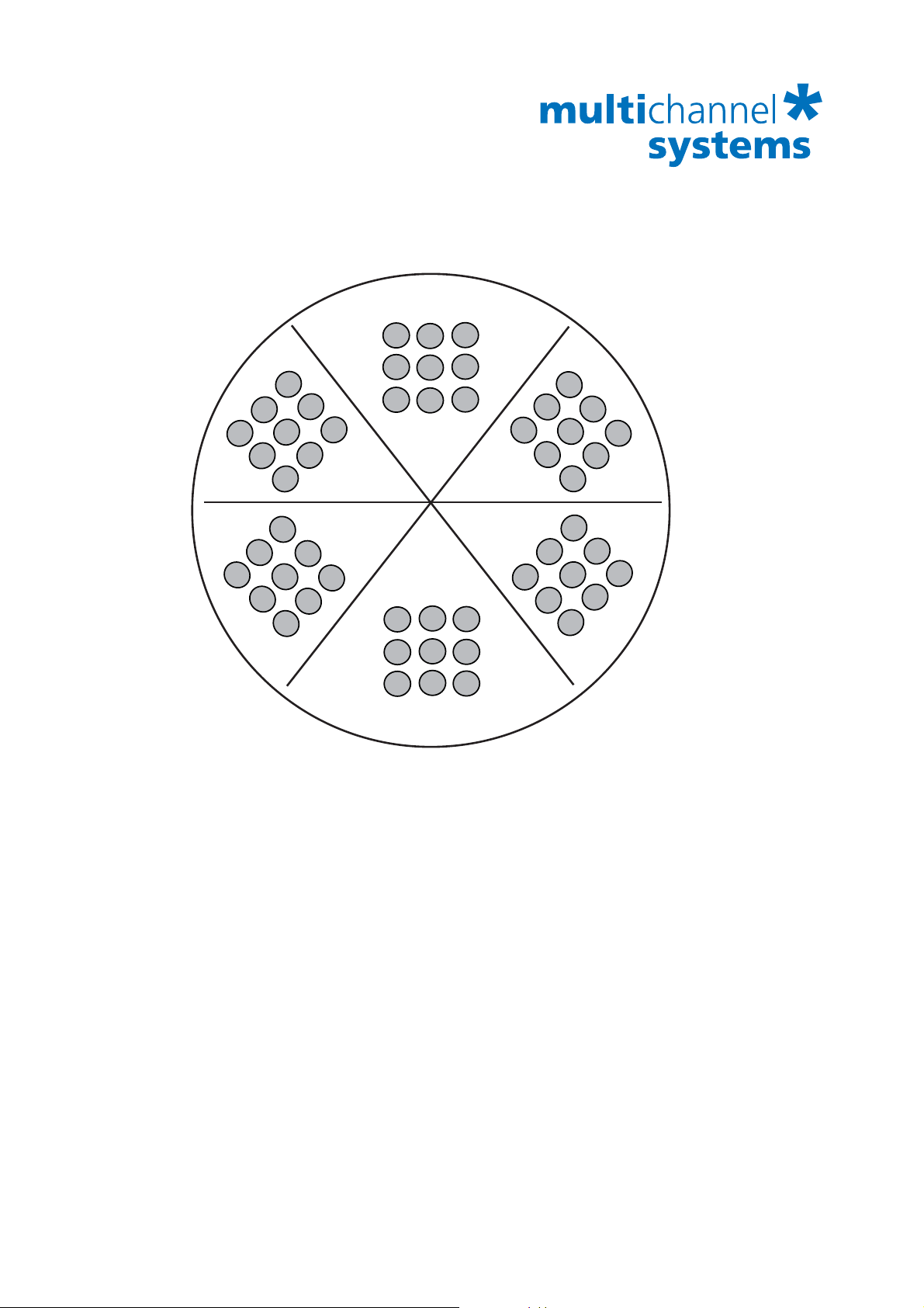
Please make sure to select in the data acquisition program MC_Rack in “Data Source
Setup”, “Source layout” 2 dim. (MEA) (= digit code) or Configuration (= letter digit
code). This is not necessary for other types of data acquisition software.
F1 F2 F3 A1 A2 A3 B1 B2 B3 The letter-digit code is
34 23 22 43 42 51 63 82 83 the electrode identifier
and refers to the position
F4 F5 F6 A4 A5 A6 B4 B5 B6 of the electrode
24 12 33 44 52 53 71 73 64 in the 60-6wellMEA.
F7 F8 F9 A7 A8 A9 B7 B8 B9 The amplifier electrode
14 13 21 31 41 54 62 72 74 numbers (digit) are in
same sequence as they
E9 E8 E7 D9 D8 D7 C9 C8 C7 are in the data display
25 27 37 45 58 68 78 86 85 of the data acquisition
software from MCS.
E6 E5 E4 D6 D5 D4 C6 C5 C4
35 26 28 46 47 55 66 87 75 Channel map:
© 2013 Multi Channel Systems MCS GmbH
E3 E2 E1 D3 D2 D1 C3 C2 C1 6-Well-MEA.cmp
 Loading...