

Page 1

Wireless2100-System
Manual
Page 2

Information in this document is subject to change without notice.
No part of this document may be reproduced or transmitted without the express written permission
of Multi Channel Systems MCS GmbH.
While every precaution has been taken in the preparation of this document, the publisher and the author
assume no responsibility for errors or omissions, or for damages resulting from the use of information
contained in this document or from the use of programs and source code that may accompany it. In no
event shall the publisher and the author be liable for any loss of profit or any other commercial damage
caused or alleged to have been caused directly or indirectly by this document.
© 2014 Multi Channel Systems MCS GmbH. All rights reserved.
Printed: 24. 09. 2014
Multi Channel Systems
MCS GmbH
Aspenhaustraße 21
72770 Reutlingen
Germany
Fon +49-71 21-90 92 5 - 0
Fax +49-71 21-90 92 5 -11
info@multichannelsystems.com
www.multichannelsystems.com
Microsoft and Windows are registered trademarks of Microsoft Corporation. Products that are referred
to in this document may be either trademarks and/or registered trademarks of their respective holders
and should be noted as such. The publisher and the author make no claim to these trademark.
Page 3

TABLE OF CONTENT
ABOUT THIS MANUAL ........................................................................................................................... 4
WELCOME TO THE WIRELESS2100-SYSTEM ......................................................................................... 5
IMPORTANT SAFETY ADVICE ................................................................................................................ 6
OPERATOR'S OBLIGATIONS ......................................................................................................................... 7
GUARANTEE AND LIABILITY ......................................................................................................................... 7
SYSTEM COMPONENTS ......................................................................................................................... 8
WIRELESS2100 HEADSTAGES ..................................................................................................................... 8
Sampling Rate .................................................................................................................................. 9
Battery Options ................................................................................................................................ 9
Modules for additional Functions ................................................................................................... 10
WIRELESS2100 RECEIVER ......................................................................................................................... 11
WIRELESS2100 INTERFACE BOARD ............................................................................................................. 12
ACCESSORIES ......................................................................................................................................... 15
SYSTEM SETUP ..................................................................................................................................... 16
MC_RACK INSTALLATION ........................................................................................................................ 16
WIRELESS2100 HARDWARE SETUP ............................................................................................................ 17
MC_RACK SETUP .................................................................................................................................. 17
OPERATING MULTIPLE HEADSTAGES ............................................................................................................ 21
Sequential Recordings .................................................................................................................... 22
Parallel Recordings ......................................................................................................................... 22
FIRST FUNCTIONAL TESTS .......................................................................................................................... 23
EXPERIMENTAL SETUP ......................................................................................................................... 24
TROUBLESHOOTING ............................................................................................................................. 26
TECHNICAL SUPPORT ........................................................................................................................... 27
APPENDIX .............................................................................................................................................. 28
TECHNICAL SPECIFICATIONS ................................................................................... 28
Pin Layout of the Interface Board ................................................................................................... 31
W2100 Interface Board: Digital IN / OUT Connector ....................................................................... 32
DATASHEETS .......................................................................................................................................... 33
CONTACT INFORMATION .......................................................................................................................... 34
Page 4

About this Manual
This manual comprises all important information about the first installation of the hardware and software
and about the daily work with the instrument. It is assumed that you already have a basic understanding
of technical and software terms. No special skills are required to read this manual. If you are using the
device for the first time, please read the important safety advice before installing the hardware and
software, where you will find important information about the installation and first steps.
The printed manual and help are basically the same, so it is up to you which one you will use. The help
offers you the advantage of scrolling through the text in a non-linear fashion, picking up all information
you need, especially if you use the Index, and the Search function. If you are going to read larger text
passages, however, you may prefer the printed manual.
The device and the software are part of an ongoing developmental process. Please understand that the
provided documentation is not always up to date. The latest information can be found in the help. Check
also the MCS web site (www.multichannelsystems.com) for downloading up-to-date manuals and
help files.
Page 5

Welcome to the Wireless2100-System
The Wireless2100 in vivo recording system is the all-in one solution for amplifying, recording, and
analyzing in vivo data from four, eight, sixteen or thirty-two channels. The system consists of small
sized headstages with integrated A/D converter, a receiver, and an interface board with connectors
for additional analog and digital data in and outputs. For data acquisition and analysis, the easy to
use software package MC_Rack is included.
Headstages are available with 4, 8, 16 or 32 channels. Each Wireless2100-System can operate with any
type of headstage. With its excellent signal-to-noise ratio, adjustable sampling rate and wide frequency
range, the W2100-Systems are a versatile solution for spikes, LFP, EEG, ECG, and ECoG. The headstage
records analog signals from the electrodes. The signals are amplified and digitized directly on the
headstage, and transmitted to the receiver via radio communication in the 2.4 GHz frequency band.
Digital data transmission guarantees a long effective range without loss in data quality. Additional in-
and outputs on the interface board allow the synchronization of the data with external devices, and the
simultaneous recording of additional analog data, for example from a microphone.
As advanced option, the Wireless2100 system allows the possibility to record from up to four
headstages with one receiver simultaneously (at a reduced sampling rate). You can connect two
receivers to one interface board, thereby building a system for up to eight headstages. It is possible to
position four receivers in one room, thereby having a four-fold system with a total of sixteen headstages,
from which you can record in parallel.
Furthermore, the modular design of the Wireless2100 headstages allows the customization with
additional functions based on customer requests. At the moment, only the basic recording option is
available. Optional modules for electrical and optical stimulation, as well as motion tracking are under
development.
Page 6
Important Safety Advice
Warning: Make sure to read the following advice prior to install or to use the device and the
software. If you do not fulfil all requirements stated below, this may lead to malfunctions or
breakage of connected hardware, or even fatal injuries.
Warning: Obey always the rules of local regulations and laws. Only qualified personnel should
be allowed to perform laboratory work. Work according to good laboratory practice to obtain
best results and to minimize risks.
The product has been built to the state of the art and in accordance with recognized safety
engineering rules. The device may only
be used for its intended purpose;
be used when in a perfect condition.
Improper use could lead to serious, even fatal injuries to the user or third parties and damage
to the device itself or other material damage.
Warning: The device and the software are not intended for medical uses and must not
be used on humans.
Malfunctions which could impair safety should be rectified immediately.
High Voltage
Electrical cords must be properly laid and installed. The length and quality of the cords must be in
accordance with local provisions.
Only qualified technicians may work on the electrical system. It is essential that the accident prevention
regulations and those of the employers' liability associations are observed.
Each time before starting up, make sure that the mains supply agrees with the specifications of
the product.
Check the power cord for damage each time the site is changed. Damaged power cords should
be replaced immediately and may never be reused.
Check the leads for damage. Damaged leads should be replaced immediately and may never be
reused.
Do not try to insert anything sharp or metallic into the vents or the case.
Liquids may cause short circuits or other damage. Keep the device and the power cords always
dry. Do not handle it with wet hands.
Requirements for the installation
Make sure that the device is not exposed to direct sunlight. Do not place anything on top of
the device, and do not place it on top of another heat producing device. Never cover the vents,
not even partially, so that the air can circulate freely. Otherwise, the device may overheat.
Page 7

Operator's Obligations
The operator is obliged to allow only persons to work on the device, who
are familiar with the safety at work and accident prevention regulations and have been instructed
how to use the device;
are professionally qualified or have specialist knowledge and training and have received instruction
in the use of the device;
have read and understood the chapter on safety and the warning instructions in this manual and
confirmed this with their signature.
It must be monitored at regular intervals that the operating personnel are working safely.
Personnel still undergoing training may only work on the device under the supervision of an experienced
person.
Guarantee and Liability
The General conditions of sale and delivery of Multi Channel Systems MCS GmbH always apply.
The operator will receive these no later than on conclusion of the contract.
Multi Channel Systems MCS GmbH makes no guarantee as to the accuracy of any and all tests and data
generated by the use of the device or the software. It is up to the user to use good laboratory practice to
establish the validity of his findings.
Guarantee and liability claims in the event of injury or material damage are excluded when they are the
result of one of the following.
Improper use of the device.
Improper installation, commissioning, operation or maintenance of the device.
Operating the device when the safety and protective devices are defective and/or inoperable.
Non-observance of the instructions in the manual with regard to transport, storage, installation,
commissioning, operation or maintenance of the device.
Unauthorized structural alterations to the device.
Unauthorized modifications to the system settings.
Inadequate monitoring of device components subject to wear.
Improperly executed and unauthorized repairs.
Unauthorized opening of the device or its components.
Catastrophic events due to the effect of foreign bodies or acts of God.
Page 8
System Components
The Wireless 2100-System consists of three main components: the headstage with battery, the receiver,
and the interface board, which is connected to the computer. Accessories are the signal generator, the
remote control to reactivate the headstage, and the USB-charger for the battery. The components are
presented in detail below.
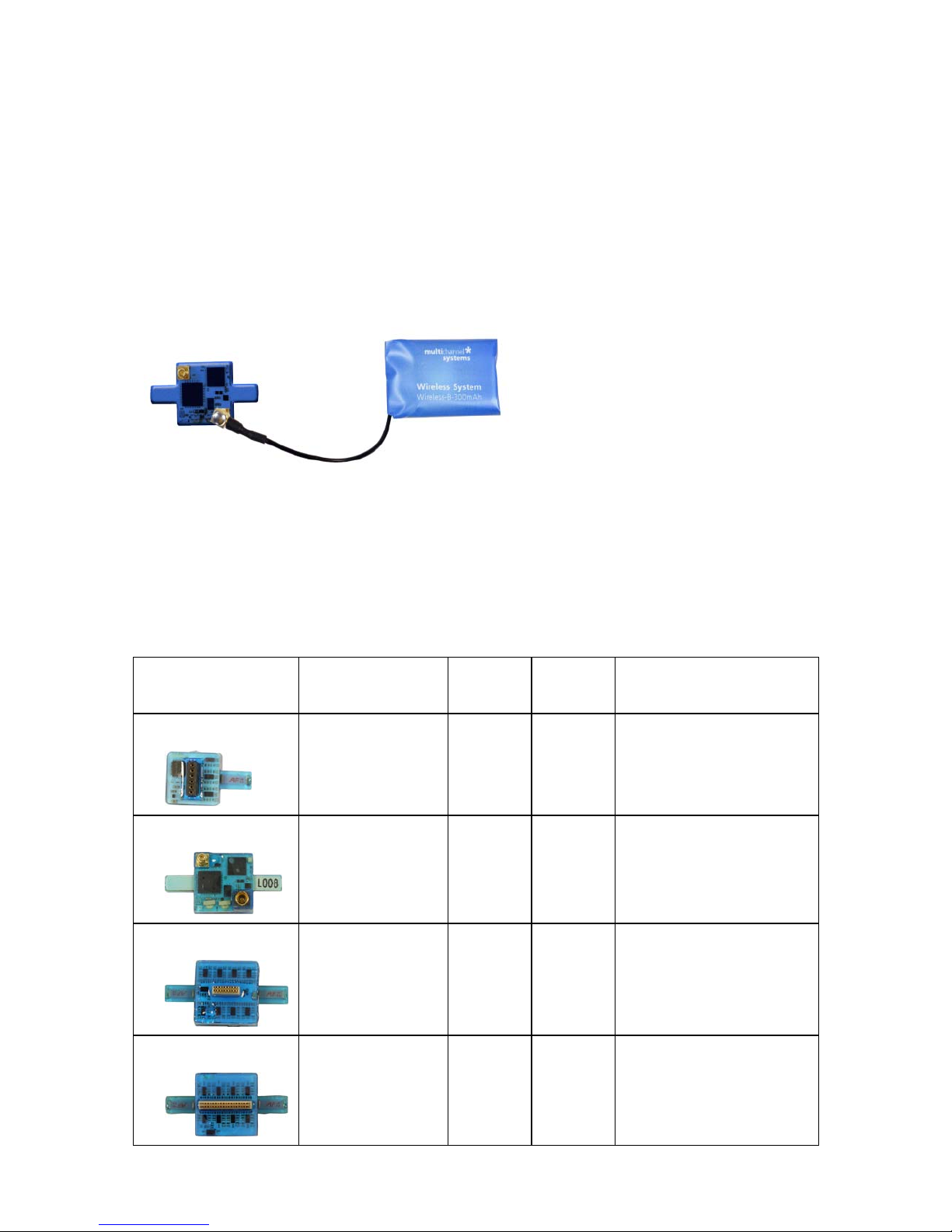
Wireless2100 Headstages
The headstage is the first of the three elements of the Wireless2100-System. The headstages are small
and lightweight to allow recordings in freely moving animals. Headstages are available with 4, 8, 16 or 32
channels. Each Wireless2100 receiver and interface board is able to operate with any type of headstage.
Headstages are equipped with Omnetics or single row connectors. Please see table below for an overview
of available headstage types/connectors. For other connector types, adaptors are available on request.
Please contact the MCS support team for detailed information.
Please see the table for the dimensions and weights of the headstages. The specifications apply to
headstages without additional functions.
Dimensions /
Weight
W in mm D in
mm
H in
mm
Weight in g
W2100-HS4
13 (+ antenna) 13 5 2.5 (+ battery)
W2100-HS8
15.5 (+ antenna) 15.5 5 2.8 with single row
connector (+ battery),
3.1 with Omnetics
connector (+ battery)
W2100-HS16
15.5 (+ antenna) 15.5 5 2.9 (+ battery)
W2100-HS32
15.5 (+ antenna) 15.5 6.7 3.7 (+ battery)
Page 9
Each headstage has a battery connector and two LEDs, blue and red. The headstages are coated with
transparent blue material as protection against water and dirt. The standard gain of the headstages
is 100, and the frequency range is 1 Hz to 5 kHz. A lower cut off frequency of 0.1 Hz is available on
request.
Sampling Rate
The Wireless2100-System can sample the maximum of 32 channels with 10 kHz per channel. Depending
on the number of selected channels, the sampling rate can be increased even more. If multiple headstages
are operated simultaneously with a single receiver, the sampling rate is limited to 2 kHz per channel. For
details please see chapter "Technical Specifications" in the Appendix.
Summary of Sampling Rates per Channel for the four Headstage Types:
W2100-HS4:
25 kHz per channel simultaneously on all 4 channels, also 40 kHz when using
2 channels.
W2100-HS8: 25 kHz per channel simultaneously on all 8 channels, 40 kHz when using
4 or 2 channels.
W2100-HS16: 25 kHz per channel simultaneously on all 16 channels, also 25 kHz when using
8 channels and 40 kHz when using 4 or 2 channels.
W2100-HS32: 10 kHz per channel simultaneously on all 32 channels, 25 kHz when using
16 or 8 channels, 40 kHz when using 4 or 2 channels.
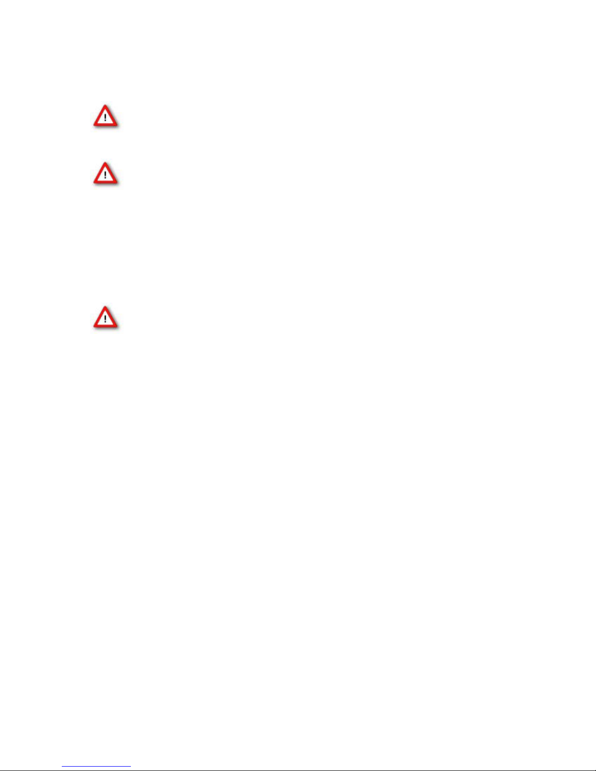
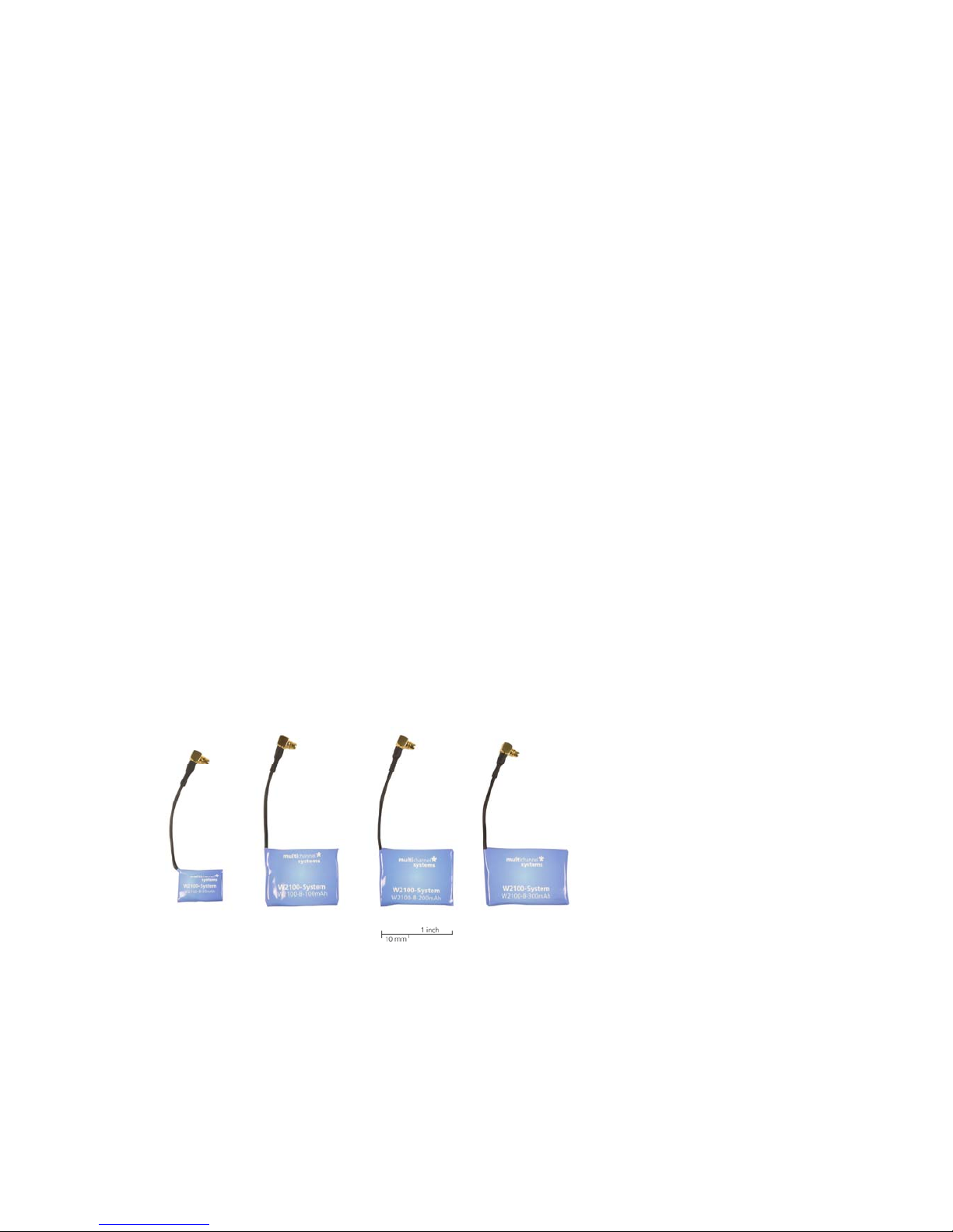
Battery Options
Batteries of the Wireless2100 are always external, not built in the headstage. Standard batteries are
available with different capacities, 30, 100, 200 and 300 mAh. Custom batteries are available on request.
They can either be connected directly on the headstage with a double plug or with a cable connection,
for example, with a backpack on the back of the animal. Backpacks for rat and mice are available as
accessories. Please see the images below.
Page 10
The standard battery (100 mAh) of a headstage permits continuous recording of all channels for more
than 2 hours. Empty batteries can be replaced without removing the headstage, and recharged while
the experiment can be continued with a second battery.
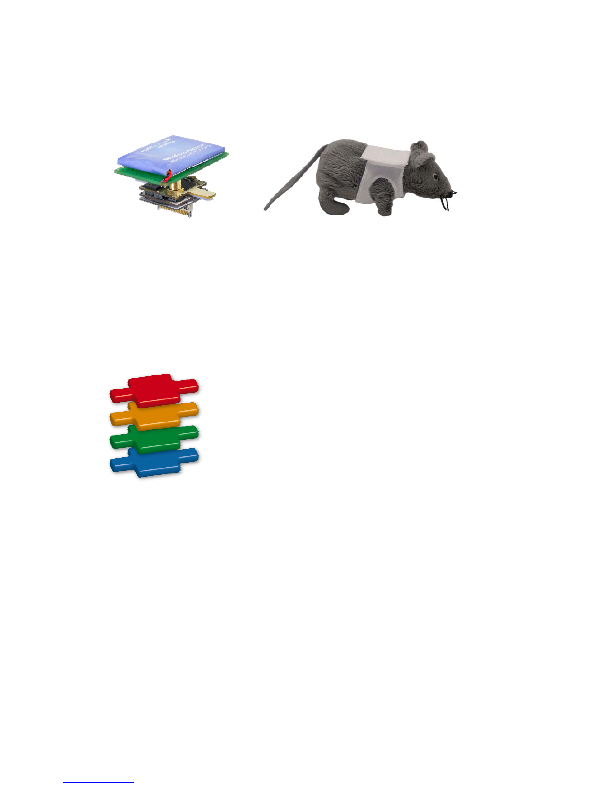
Modules for additional Functions
W2100 headstages have a modular design. Layers with additional functions are only added on request,
to avoid unnecessary weight and cost.
At the moment, only the basic recording option is available. Optional modules for electrical and optical
stimulation, as well as motion tracking are under development. It will be possible to customize
a headstage when it is ordered, and add additional layers with additional functions. A modification
of already existing headstages is not possible.
Page 11
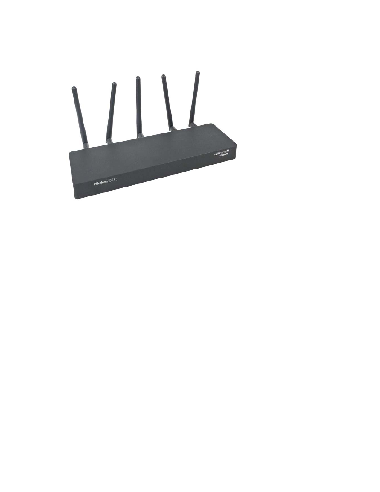
Wireless2100 Receiver
The receiver is the second element of the Wireless2100-System.
One receiver of the Wireless2100-System can receive the digitized signals sent from up to four
headstages. Four antennas are used for data transmission, one antenna submits control signals to and
from the headstage. The position of the antennas can have an influence on the transmission efficiency.
With a clear line of sight between sender and receiver, an effective transmission range of 5 m is
guaranteed under normal circumstances. Under good conditions, the actual range can be much further.
The receiver does not need an own power supply. The device is connected to the interface board via
eSATAp cable for data transfer and power supply.
Page 12
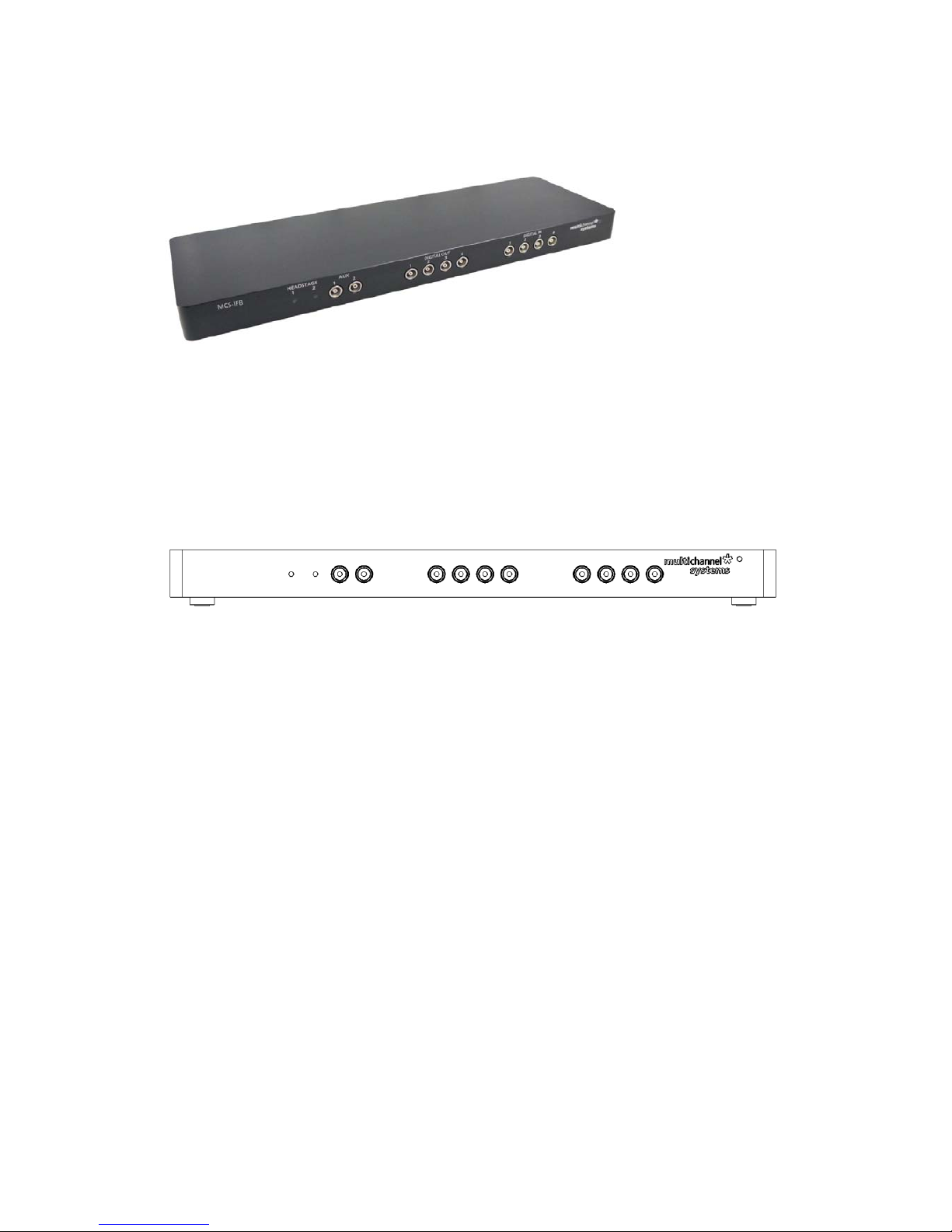
Wireless2100 Interface Board
The interface board is the third element of the Wireless2100-System. It provides connectors for
additional analog input channels and digital trigger in- and outputs.
The interface board is connected to the receiver with an eSATAp cable. The connection to the data
acquisition computer is realized via USB 2.0 high speed cable. The interface board has an own power
supply.
Front Panel of the MCS Interface Board
Two Status LEDs
The status LEDs indicate the link status of receiver 1 and / or receiver 2. They light up when one or both
receivers are connected to the interface board via eSATAp cable.
Auxiliary Channels
Two reserve auxiliary channels are available for future use. They have no function at the moment.
Digital IN / OUT
A Digital IN / OUT for 16 digital in- and output bits is available (68-pin MCS standard connector) on the
rear panel of the interface board. On the front panel four digital IN and four digital OUT connectors bits
are also accessible via Lemo connector, DIG IN bit 0 to bit 3 and DIG OUT bit 0 to bit 3. If access to more
bits of the DIG IN / OUT channel is required, it is necessary to connect a Di/o board with a 68-pin standard
cable. This Di/o board is available as optional accessory.
Power LED
The power LED near to the MCS logo on the front panel of the interface board should light up when
the Wireless2100-System is "ON", and the device is connected to the power line. If not, please check
the power source and cabling.
Page 13

Rear Panel of the MCS Interface Board
Toggle Switch On / Off
Toggle switch for turning the device on and off. The Wireless2100-System is switched to status "ON"
when the toggle switch is switched to the left. The device is switched "OFF" when the toggle switch is
switched to the right. If the Wireless2100-System is "ON", and the device is connected to the power line,
the power LED on the front panel of the interface board should light up. If not, please check the power
source and cabling.
Power IN
Connect the power supply unit here. This power supply powers both, the headstage and the interface
board of the Wireless2100-System. The device needs 12 V and 2.5 A / 30 W.
Ground
If an additional ground connection is needed, you can connect this plug with an external ground using
a standard 4 mm jack.
Digital IN / OUT
A Digital IN / OUT for 16 digital in- and output bits is available (68-pin MCS standard connector). Please
read chapter "Pin Layout" (Digital IN / OUT Connector) in the Appendix for more information about the
pin layout of the connector. The Digital IN / OUT connection accepts or generates standard TTL signals.
TTL stands for Transistor-Transistor Logic. A TTL pulse is defined as a digital signal for communication
between two devices. A voltage between 0 V and 0.8 V is considered as a logical state of 0 (LOW),
and a voltage between 2 V and 5 V means 1 (HIGH).
The Digital OUT allows generating a digital signal with up to 16 bits and read it out, for example, by
using a Digital IN / OUT extension Di/o from Multi Channel Systems MCS GmbH. You can utilize this
digital signal to control and synchronize other devices with the Wireless2100-System. Bit 0 to 3 of the
Digital OUT are separated and available as Lemo connector DIG OUT 0 to 3 on the front panel of the
interface board. So if you need only one, two, three or four bits of the digital signal, you don’t need the
additional Di/o.
The Digital IN can be used to record additional information from external devices as a 16 bit encoded
number. The Digital IN is most often used to trigger recordings with a TTL signal. The 16 bit digital input
channels is a stream of 16 bit values. The state of each bit (0 to 15) can be controlled separately. Standard
TTL signals are accepted as input signals on the digital inputs. Unused input bits, which have an undefined
state, should be masked in the "Trigger Detector" of MC_Rack.
Warning: A voltage that is higher than +5 Volts or lower than 0 Volts, that is, a negative voltage, applied
to the digital input would destroy the electronics. Make sure that you apply only TTL pulses (0 to 5 V) to
the digital inputs.
Page 14

Analog Channels
Eight Analog IN channels are available via 20 pin connector. Please read chapter "Pin Layout" (Analog IN
Connector) in the Appendix for more information. The additional analog inputs are intended for recording
additional information from external devices, for example data from a microphone Two of the eight
analog channels (analog channel 1 and 2) are directly accessible via two Lemo connectors. Signals on
the analog channels are amplified with a gain factor of 2.
Two USB Connectors
Both USB connectors are used to transfer the amplified and digitized data from all data channels and the
additional digital and analog channels to any connected data acquisition computer via USB high speed 2.0
(type A - mini B) cable. Data from one receiver (1) is transmitted via USB connector 1, and the data from
the second receiver (2) via USB connector 2. While using only one receiver, it is not necessary to connect
the second USB.
Important: It is recommended to connect the USB cables to different USB ports of the computer.
Do not use an USB hub!
Audio OUT
To the Audio Out (3.5 mm phone jack) you can connect an audio system to make the electrical activity
audible. This audio output is real-time. Headphones or a speaker can be connected directly to the AUDIO
OUT. Only two channels at a time can be converted into sound (Stereo).
Side Panel
Sockets for connecting up to two receivers via eSATAp cable.
Please use the connector labelled HS/RE 1 when working with one receiver only.
Page 15

Accessories
Default accessories of the Wireless2100-System are the signal generator, the remote control to reactivate
the headstage, and the USB charger for the battery.
ME/W-Signal Generator
The ME/W-System Signal Generator can generate a number of pre-defined sine waves and artificial
biological waveforms and feed it into all types of headstages. With those artificial signals it is possible
to test the functionality of the complete system without the need to use an actual animal. Please read
the ME/W-SG data sheet in the "Appendix" for connecting and operating the ME/W-Signal Generator.
Charging Set
The charging set for the battery works via any USB connector. To recharge the battery, please connect
the charging set to an USB port of the computer and plug the battery into the back of the charger with
the provided adaptor cable W2100-C-B-Ch. The regular charger Wireless-C-HC is used for batteries with
100, 200 or 300 mAh. The charger Wireless-C-LC is used for the 30 mAh battery only.
Important: Charging the 30 mAh battery with the wrong charger can lead to severe damage and even
fire! Do not recharge any battery without supervision!
The red LED on top indicates that the device is on. The yellow LED indicates that the battery is being
recharged. After approximately one hour the green LED indicates the end of process.
Remote Control
The headstages can be switched off with a wireless software command. To reactivate the headstage,
it is either necessary to disconnect and reconnect the battery, or to turn it back on with the remote
infrared remote control Wireless-F. Just point the remote control at the headstage and press the button.
You need to aim at the receiving LEDs next to the battery connector with a distance of 5-10 cm.
Page 16

System Setup
The following chapter describes how to set up the hardware and software and test the functionality
of the Wireless2100-System.
MC_Rack Installation
System Requirements
One of the following Microsoft Windows ® operating systems is required: Windows 8.1, Windows 7,
Vista, or XP (English and German versions supported) with the NT file system. Other language versions
may lead to software errors.
Recommended operating system settings
The following automatic services of the Windows operating system interfere with the data storage on the
hard disk and can lead to severe performance limits in MC_Rack. These routines were designed for use on
office computers, but are not very useful for a data acquisition computer.
Turn off automatic Windows Update.
Deselect Windows Indexing Service for all local disks.
Turn off Optimize hard disk when idle (automatic disk fragmentation).
It is also not recommended to run any applications in the background when using MC_Rack.
Remove all applications from the Autostart folder.
Be careful when using a Virus Scanner. These programs are known to disturb MC_Rack,
and even data loss may occur.
When using a Wireless2100-System it is recommended to connect a high performance computer
with a separate hard disc for program files and data storage. The provided possibility to make long term
experiments with a sample rate of up to 40 kHz needs high memory capacity. Please remove data and
defragment the hard disc regularly to ensure optimal performance.
Installation
Please check the system requirements before you install the software. MCS cannot guarantee
that the software works properly if these requirements are not fulfilled.
Important: Please make sure that you have full control over your computer as an administrator.
Otherwise, it is possible that the installed software does not work properly.
Double-click Setup.exe on the installation volume.
The installation assistant will show up and guide you through the installation procedure.
Follow the instructions of the installation assistant.
The Wireless2100-System driver and MC_Rack are installed (or updated) automatically. MC_Rack
is updated on a regular basis. Please check the Download section of the MCS website to get the latest
version for free (http://www.multichannelsystems.com/software/mc-rack).
Page 17

Wireless2100 Hardware Setup
Place the receiver within transmission range of your experimental setup. To get optimal results,
keep the distance as short as possible.
Place the interface board not further then 2 m away from the receiver, and connect the two with
the eSATAp cable.
Connect the power supply to the interface board.
Connect the interface board with a USB2.0 port of a computer where MC_Rack is already installed.
Avoid USB 3.0 ports (USB 3.0 ports are blue). Do not use USB hubs.
Switch on the Wireless2100-System on the interface board. LEDs on the interface board and receiver
should light up.
Connect a charged battery to a headstage.
MC_Rack Setup
Start MC_Rack. To define the Wireless2100-System as data source, please open the "Data Source
Setup" in the "Edit" menu.
Page 18

The "Channel Layout" dialog opens.
Select "USB" in the left "Data Source" drop down menu. The “Wireless W2100” is automatically
selected. Click "Configuration" in "Source Layout".
Enable the check box "Digital Input Channel" if you want to display external TTL signals, fed into the
Wireless2100-System via Lemo connectors on the interface board. Deselect the check box, if you do not
need additional digital channels.
Add the “Wireless W2100-System” via "Edit" menu to the virtual rack.
Click "Hardware" tab.
Page 19

“Settings” Window of Hardware Tab
Most of the settings are predefined. Click the “Sampling Frequency” drop down menu and select
the desired sampling rate. The sampling rate depends on the type of the headstage and the number
of channels in use. In the example on the upper screenshot an 8-channel type headstage is selected.
When recording with all eight available channels the sampling rate is limited to 25 kHz. Recording
with one to four channels only is possible with a sampling frequency of up to 40 kHz.
“Offset Correction” Window of the Hardware Tab
The “Offset Correction” can be used to correct for offsets caused by the connected electrode. The
“Learn Offset” button detects the difference to 0 on all channels individually. Activating the "Offset
Correction" function will subtract those differences from all incoming data to correct the offset.
„Wireless” Window of Hardware Tab
The additional “Wireless” control panel is an extension of the hardware tab, which is only visible
if a Wireless2100-System is connected.
Click button "Scan" to see all available headstages. Headstages are only available for the system if the
battery is connected, if they are within transmitting range, and have not been switched off previously
by software command.
On the right side the "Available Headstages" are listed with type and serial number. Highlight the desired
headstage and click “Select”. The headstage will now be displayed in the "Selected Headstage" window.
The serial number, the type and the status of the battery charging is displayed. Deselect the headstage
by clicking the button "Deselect". The LEDs on the selected headstage will blink, if they have not been
switched off. In the example above the blue LED is in “Blink” mode, the red LED is off.
On the “Channel” list, any combination of channels can be selected for recording. On the screenshot
above, the first 16 channels of the headstage are selected. Deactivation of channels reduces energy
consumption of the headstage and might allow higher sampling rates
A selected headstage which is not recording is in stand by mode, where it uses about 10 % energy
compared to active recording. To shut it down completely, use the “Switch Off” button. A headstage
which has been switched off will no longer show up in a scan. To reactivate it, you need to shortly
disconnect the battery, or use the infrared “IR-Remote Control”. Aim at the headstage from 5 to
10 cm distance.
Page 20

The LEDs can be used for motion tracking and/or as status indicator of the headstage. They can be set
to “On”, “Off” or “Blink”. LEDs set to “On” will be on all the time on a selected headstage, regardless
of the recording status. If they are set to blink, they will blink slowly in standby mode and faster while
the headstage is acquiring data.
Click the "Info" tab of the dialog.
In this tab "Infos" about the connected Wireless2100-System are listed.
Click the "Audio" tab of the dialog.
On the interface board of the Wireless2100-System you can connect an audio system "Audio OUT"
(3.5 mm phone jack) to make the electrical activity audible. This audio output is real-time. Headphones
or a speaker can be connected directly to the Audio OUT. Only two channels at a time can be converted
into sound. Select one "Mono" or two "Stereo" channels, switch the audio channels on and off and
adjust the sound volume via the sliders.
Page 21

Data Display
Add a data display to the rack
. By default, the available channels will be displayed in numeric order.
To design a display layout which resembles the layout of a specific electrode, select the "Layout" tab
of the display. You can design a grid with a number of rows and columns of your choice. Each electrode
channel can be assigned to any position. Once created, this configuration can be saved as user channel
map (”*.cmp” file) for future use. See below a layout for an electrode with four shanks, with four
electrodes each.
Operating multiple Headstages
It is possible to operate different headstages connected to one Wireless2100-System. The headstages
are discriminated via frequency band for the radio communication. Each headstage is labelled by the
type (W16) and the serial number (S/N 1230). Please see the bill of delivery for the assignment of the
headstage and the frequency band.
Page 22

Sequential Recordings
After pressing the button “Scan” the receiver scans for available headstages in range. Then the user
is able to select the desired headstage. Click on one of the headstages in the "Available Headstages"
window and press the button "Select".
After recording from the first headstage, deselect the headstage by clicking the button "Deselect".
Now you can choose a different headstage and repeat the process. For sequential recording, the full
sampling rate for the respective headstage type is available.
Parallel Recordings
Operating multiple Wireless2100-Headstages in parallel with one computer is still under development.
It will be possible to run two receivers connected to one interface board, each recording from up to four
headstages in simultaneously.
To control the different recordings independently, start one instances of MC_Rack for each headstage.
In “Data Source Setup” assign the Wireless2100 receivers via serial number to the instances of MC_Rack.
With a maximum of eight instances, it is possible to select a different headstage in each MC_Rack
instance and control the recording independently. Already selected headstages become invisible
for other scanning receivers. When doing parallel recordings, the sampling rate is limited to 2 kHz.
Page 23

First functional Tests
Set up the Wireless2100 hard- and software as described above. Make sure all components are connected
and the Wireless2100-System is switched on at the interface board. Connect a charged battery and the
ME/W-Signal Generator to your headstage. See the ME/W-Signal Generator datasheet in the Appendix
for details on connector and orientation.
Open the MC_Rack software and build a rack with a Wireless2100 data source and a data display as
described above. At the signal generator, select the signal type “Spikes”. You should see a noise level
of about 20 μV (peak to peak) and a signal amplitude for the largest spikes of 360 μV.
Page 24

Experimental Setup
First step to set up an experiment with the Wireless2100-System is to implant an electrode into the
laboratory animal. The electrode has to be fixed to the skull, for example with dental cement, to
guarantee a stable positioning of the electrode in the desired area of the brain. The electrode connector
must be available on the skin surface of the animal. A ground electrode is essential, a reference electrode
is recommended.
Battery Options
Make sure that the battery of the headstage is charged and plugged in properly. The battery can be fixed
on top of the headstage or it can be stored in a special backpack on the back of the animal. Batteries are
available either with a cable or fixed on a circuit board with a double connector to be plugged in directly
on the headstage, please see the images below.
Use of the Reference and Ground Electrodes
For optimal signal quality in in vivo experiments it is necessary to provide a good grounding (GND) and a
well placed reference (REF) electrode. Therefore all headstages of the Wireless2100-System are equipped
with dedicated pins for a ground and a reference electrode.
The reference electrode should be out of a similar or the same material as the recording electrodes and
it should be of comparable size. The reference is ideally placed near the recording electrodes, but not in
active tissue.
The signals from all electrodes are amplified and then each signal from the recording electrodes is
compared to the signal from the reference electrode. The difference is measured by the analog to digital
converter (ADC) and digitized.
Page 25

When external interferences, for example heartbeats, muscle potentials, breathing, disturb the
measurements, both, the recording and the reference electrodes measure the same disturbance and the
noise signal is removed because only the difference between recording and reference electrode is digitized
and transmitted (Common Mode Rejection).
To make sure that the animal and the headstage are set to the same electrical potential, a ground
connection is also necessary. A good ground option is usually a large conductor, such as a scull screw
or a silver wire implanted under the skin of the animal.
Important: Please connect all unused inputs of the headstage to ground (GND) to prevent floating!
If you do not use all inputs of a headstage, for example, when using a headstage with eight channels
and a probe with four electrodes, the open channels are floating and disturb the recording of the
connected channels. It is necessary to ground the open channels physically. Deselecting the channels
in the “Hardware” tab of the software has no effect.
Positioning of the System Components
If possible, always provide a clear line of sight between the headstage and the receiver and keep the
distance as short as possible. In a larger cage, ideally position the receiver in the centre on top of the
cage. The position of the antennas does have an influence on the quality of the connection, so in case
of connection issues, it might help to play around with the antenna positions. Two out of five antennas
receive data from one transmitter on the headstage. One antenna is for metadata only. In theory, the
ideal position is if the two antennas of one receiver are orthogonal to each other, like in the image below.
However, as the signal is reflected by surrounding objects, the ideal position can be quite different in each
setup.
Optimizing Energy Consumption
The power consumption of the Wireless2100 headstage mainly depends on two parameters: The number
of channels and the sampling rate. To save power, the headstage automatically goes to standby mode
while not acquiring data. To decrease the power consumption while recording the most effective
measures are to decrease the sampling rate as far as possible and switch off channels with irrelevant data.
While not doing experiments, it is recommended to disconnect the battery or switch the headstage off via
software command. It is also possible to decrease the sending power of the transmitters, if the distance
between headstage and receiver is small.
Page 26

Troubleshooting
Most problems occur seldom and only under specific circumstances. In most cases, it is only a minor
problem that can be easily avoided or solved.
If the problem persists, please contact your local retailer. The highly qualified staff will be glad to help you.
Please inform your local retailer as well, if other problems that are not mentioned in this documentation
occur, even if you have solved the problem on your own. This helps other users, and it helps MCS to
optimize the instrument and the documentation.
Please pay attention to the safety and service information of chapter "Important Safety Advice".
Multi Channel Systems MCS GmbH has put all effort into making the product fully stable and reliable,
but like all high-performance products, it has to be handled with care.
Potential Problems
The headstage sends signals to the receiver in 2.4 GHz frequency band. That is why devices, working
in the same frequency band may disturb the data communication between headstage and receiver.
Please do not use, for example, a mobile phone equipped with blue tooth or a WLAN connection or
a microwave in the vicinity of headstage and receiver otherwise it may cause trouble in data transfer.
Important: For bandwidth reasons it is not recommended to use an USB hub to connect the
Wireless2100-System to your computer.
Page 27

Technical Support
Please read the "Troubleshooting" part of the manual or help first. Most problems are caused by minor
handling errors. Contact your local retailer immediately if the cause of the trouble remains unclear. Please
understand that information on your hardware and software configuration is necessary to analyze and
finally solve the problem you encounter.
If you have any question or if any problem occurs that is not mentioned in this documentation, please
contact your local retailer. The highly qualified stuff will be glad to help you.
Please keep information on the following at hand
Description of the error (the error message text or any other useful information) and of the context
in which the error occurred. The more information on the actual situation you can provide, the easier
it is to track the problem.
The serial number of the device. You will find it on the bottom side of the main unit.
The software of MC_Rack version you are currently using. On the "Help" menu, click "About
MC_Rack". The displayed dialog box shows the version number.
The hardware version of the Wireless2100-System you are currently using is displayed in the
“Hardware” tab of the starting dialog.
The operating system and service pack number on the connected computer.
The hardware configuration (microprocessor, frequency, main memory, hard disk) of the connected
computer. This information is especially important if you have modified the computer or installed new
hard- or software recently.
Storage Batteries
Batteries and accumulators do not belong in normal household waste and, thus, must always be disposed
of within the framework of existing legislation.
Please store the batteries absolutely dry at a temperature of about 10 °C.
Page 28

Appendix
Technical Specifications
The Wireless2100-System is a 4-, 8-, 16- or 32-channel wireless in vivo system with headstage,
receiver and interface board. Analog signals are converted in digital data streams in real-time.
Warning: The devices may only be used together with Wireless2100-Systems from Multi Channel
Systems MCS GmbH, and only for the specified purpose. Damage of the devices and even fatal
injuries can result from improper use. Do not open the receiver or the interface box and do not
change hardware configuration as it could lead to improper behavior of the system.
General characteristics
Operating temperature 10 °C to 50 °C
Storage temperature 0 °C to 50 °C
Relative humidity 10 % to 85 %, non-condensing
Headstage
Dimensions
(W x D x H)
W2100-HS4 13 x 13 x 5 mm (+ antennae)
W2100-HS8 15.5 x 15.5 x 5 mm (+ antennae)
W2100-HS16 15.5 x 15.5 x 5 mm (+ antennae)
W2100-HS32 15.5 x 15.5 x 6.7 mm (+ antennae)
Weight
W2100-HS4 approx. 2.5 g (+ battery)
W2100-HS8 approx. 2.8 g single row connector
(+ battery)
W2100-HS8 approx. 3.1 g Omnetics connector
(+ battery)
W2100-HS16 approx. 2.9 g (+ battery)
W2100-HS32 approx. 3.7 g (+ battery)
Number of analog recording channels 4, 8, 16 or 32
Page 29

Amplifier integrated in the headstage
Bandwidth 1 Hz to 5 kHz (0.1 Hz on request)
Resolution 16 bit
Input voltage range + / - 12.4 mV
Sampling rate
Sampling Rate
in kHz/channel
Number of selected channels
2 4 8 16 32
W2100-HS4 40 25
W2100-HS8 40 40 25
W2100-HS16 40 40 25 25
W2100-HS32 40 40 25 25 20
Max. distance
for wireless link
5 m guaranteed (under normal circumstances)
Storage battery
Storage battery Lithium polymer, rechargeable
Dimensions (W x D x H)
of battery
30 mAh 17 x 11 x 3 mm
100 mAh 26 x 19.5 x 2.3 mm
200 mAh 26 x 20 x 4.5 mm
300 mAh 27.5 x 19.5 x 5 mm
Weight of battery
30 mAh approx. 1.7 g
100 mAh approx. 4.1 g
200 mAh approx. 5.5 g
300 mAh approx. 8.1 g
Recording time of batteries
in hours at maximal sampling rate
on all available channels
W2100-
HS4
W2100HS8
W2100HS16
W2100-
HS32
30 mAh 0.6 0.4 0.4
100 mAh 2 1.3 1.2
200 mAh 4 2.5 2.3
300 mAh 6.1 3.8 3.5
Recharging Device
Dimensions (W x D x H) 55 mm x 20 mm x 10 mm
Period of charging 1 hour
Power USB powered
Page 30

Receiver
Dimensions (W x D x H) 110 mm x 78 mm x 29 mm
Frequency band 2.4 GHz
Impedance of antennae 50 Ohm
Interface Board
Dimensions (W x D x H) 110 mm x 78 mm x 29 mm
Control interface USB 2.0 High Speed
Software
Operating system Microsoft Windows ® 8.1, Windows 7,
Windows XP or Vista with NTFS,
English and German version supported
MC_Rack program
Data acquisition and analysis software
Version 4.5.1 and higher
MC_DataTool program
Data export software
Version 2.6.13 and higher
Axon binary file (*.abf), ASCII file (*.txt),
binary file (*.raw)
Page 31

Pin Layout of the Interface Board
W2100 Interface Board: 20-Pin Connector (Analog IN)
20-Pin Connector for Analog IN and DSP
TMS
Pin 1
Pin 2 TRST
TDI
Pin 3 Pin 4 GND
3V3
Pin 5 Pin 6 KEY
TDO
Pin 7 Pin 8 GND
RTCK
Pin 9 Pin 10 GND
TCK
Pin 11 Pin 12 GND
BMU 0
Pin 13 Pin 14 EMU 1
Analog IN channel 3 Pin 15 Pin 16
Analog IN channel 4
Analog IN channel 5 Pin 17 Pin 18
Analog IN channel 6
Analog IN channel 7 Pin 19 Pin 20
Analog IN channel 8
MEA2100 Interface Board: Lemo Connectors for Analog IN
Analog IN 1 and 2, available via Lemo Connectors
Analog IN 1
Channel 1
Analog IN 2
Channel 2
The gain factor for amplification of all analog channels is 2.
Page 32

W2100 Interface Board: Digital IN / OUT Connector
68-Pin MCS Standard Connector
Pin 1 GNDP (power ground)
Pin 2
GNDS (signal ground)
Pin 3 - 10 Digital output channels bit 0 - 7
Pin 11 - 14
GNDS (signal ground)
Pin 15 - 22 Digital output channels bit 8 - 15
Pin 23 - 26 GNDS (signal ground)
Pin 27 - 34 Digital input channels bit 0 - 7
Pin 35 - 38 GNDS (signal ground)
Pin 39 - 46 Digital input channels bit 8 - 15
Pin 47 - 48
GNDS (signal ground)
Pin 49 - 63 Internal use (do not connect)
Pin 64 - 66 GNDS (signal ground)
Pin 67 Positive supply voltage output
Pin 68 Negative voltage supply output
Digital IN / OUT, separate available via Lemo Connectors
Separate Digital IN Lemo Connectors
Digital In 1 Bit 0 of the 16 bit digital input channels (Pin 27)
Digital IN 2 Bit 1 of the 16 bit digital input channels (Pin 28)
Digital IN 3 Bit 2 of the 16 bit digital input channels (Pin 29)
Digital IN 4 Bit 3 of the 16 bit digital input channels (Pin 30)
Separate Digital OUT Lemo Connectors
Digital OUT 1 Bit 0 of the 16 bit digital output channels (Pin 3)
Digital OUT 2 Bit 1 of the 16 bit digital output channels (Pin 4)
Digital OUT 3 Bit 2 of the 16 bit digital output channels (Pin 5)
Digital OUT 4 Bit 3 of the 16 bit digital output channels (Pin 6)
Page 33

Datasheets
Page 34

Multi Channel Systems
MCS GmbH
Aspenhaustrasse 21
72770 Reutlingen
Germany
Fon +49-7121-9 09 25-
0
Fax
+49-7121-9 09 25-11
info@multichannelsystems.com
www.multichannelsystems.com
© 2014 Multi Channel Systems MCS GmbH
Product information is subject to change
without notice.
W2100-HS4-Headstage
Pin Layout of the 4-Channel Headstage for the Wireless2100-System
multichannel
systems
*
Connector for W2100-HS4-Headstage
The connector mates with a standard
single row 1.27 mm pin connector such as:
preci-dip 850-10-006-10-001101
W2100-HS4-Headstage with single row socket
Diagram of the bottom side with pin layout:
W2100-HS4-Headstage bottom side:
Connector for the electrode probe
or for the ME/W-Signal generator.
GND REF 4 3 2 1
Storage battery
connector on the
opposite side
for orientation.
Please orientate the headstage
as shown in the diagram.
Pin Layout of the single row precession socket (1.27 mm, round pin).
GND Ground
REF Reference
E1 to E4 Electrode 1 to Electrode 4 = MC_Rack Channel 1 to Channel 4
W2100-HS4 top side:
Please use the connector in the lower
right (storage battery) for orientation
of the headstage.
Page 35

Technical Specifications
W2100-HS4-Headstage
Number of channels 4
Dimensions (W x D x H) 13 x 13 x 5 mm
(w/o antennae)
Weight (w/o battery) 2.5 g
Amplifier integrated in the Headstage
Bandwidth 1 Hz to 5 kHz (0.1 Hz on request)
Input impedance 1 G|| 10 pF
Resolution 16 bit
Sampling rate
4 channels simultaneously 25 kHz
2 channels simultaneously 40 kHz
Input voltage range + / - 12.4 mV
Distance for wireless link 5 m guaranteed under normal conditions
Batteries
Dimensions in mm Weight in g
Length Width Height Weight
30 mAh battery 17 11 3 1.7
100 mAh battery 26 19.5 2.3 4.1
200 mAh battery 26 20 4.5 5.5
300 mAh battery 27.5 19.5 5 8.1
Recording Time of batteries in hours at maximal sampling rate on all four channels
W2100-HS4
30 mAh battery 1.0
100 mAh battery 3.2
200 mAh battery 6.4
300 mAh battery 11.2
Multi Channel Systems
MCS GmbH
Aspenhaustrasse 21
72770 Reutlingen
Germany
Fon +49-7121-9 09 25-
0
Fax
+49-7121-9 09 25-11
info@multichannelsystems.com
www.multichannelsystems.com
© 2014 Multi Channel Systems MCS GmbH
Product information is subject to change
without notice.
multichannel
systems
*
W2100-HS4-Headstage
Page 36

Multi Channel Systems
MCS GmbH
Aspenhaustrasse 21
72770 Reutlingen
Germany
Fon +49-7121-9 09 25-
0
Fax
+49-7121-9 09 25-11
info@multichannelsystems.com
www.multichannelsystems.com
© 2014 Multi Channel Systems MCS GmbH
Product information is subject to change
without notice.
W2100-HS8 Headstage
Pin Layout of the 8-Channel Headstage for the Wireless2100-System
multichannel
systems
*
Pin Layout of the single row precession socket (1.27 mm, round pin).
Please orientate the headstage as shown in the diagram.
GND Ground
REF Reference
E1 to E8 Electrode 1 to Electrode 8 = MC_Rack Channel 1 to Channel 8
W2100-HS8 top side:
Please use the connector in the lower
right (storage battery) for orientation
of the headstage.
W2100-HS8 bottom side:
Connector for the electrode probe
or the ME/W-Signal generator.
W2100-HS8-Headstage with single row socket
Diagram of the bottom side with pin layout.
Connector for W2100-HS8-Headstage
with single row socket
The connector mates with a standard
single row 1.27 mm pin connector such as:
preci-dip
850-10-010-10-001101
Storage battery
connector on the
opposite side
for orientation.
GND REF E1 E2 E3 E4 E5 E6 E7 E8
Please orientate the headstage
as shown in the diagram.
Page 37

Multi Channel Systems
MCS GmbH
Aspenhaustrasse 21
72770 Reutlingen
Germany
Fon +49-7121-9 09 25-
0
Fax
+49-7121-9 09 25-11
info@multichannelsystems.com
www.multichannelsystems.com
© 2014 Multi Channel Systems MCS GmbH
Product information is subject to change
without notice.
W2100-HS8 Headstage
Pin Layout of the 8-Channel Headstage for the Wireless2100-System
multichannel
systems
*
W2100-HS8 top side:
Please use the connector in the lower
right (storage battery) for orientation
of the headstage.
W2100-HS8 bottom side:
Connector for the electrode probe
or the ME/W-Signal generator.
Connector for W2100-HS8
with Omnetics socket A79039-001
This Omnetics connector mates
with Omnetics connectors such as:
Through-Hole:
A79038-001 (NPD-18-DD-GS)
Horizontal Surface Mount:
A79040-001 (NPD-18-AA-GS)
Vertical Surface Mount:
A79042-001 (NPD-18-VV-GS)
Cable (18.0" 34 AWG lead-wire):
A79044-001 (NPD-18-WD-18.0-C-GS)
W2100-HS8 with Omnetics connector A79039-001
(NSD-18-DD-GS, female 2 guide posts)
Diagram of the bottom side with pin layout.
Pin Layout of the Omnetics socket A79039-001
Please orientate the headstage as shown in the diagram.
Guide post
NC Not connected
GND Ground
REF Reference
E1 to E8 Electrode 1 to Electrode 8 = MC_Rack Channel 1 to Channel 8
Storage battery
connector on the
opposite side
for orientation.
REF
GND
NC NC NC NC NC NC NC NC
Please orientate the headstage
as shown in the diagram.
REF E1 E2 E3 E4 E5 E6 E7 E8 GND
Page 38

Technical Specifications
W2100-HS8 Headstage (Omnetics or single row connector)
Number of channels 8
Dimensions (W x D x H) 15.5 x 15.5 x 5 mm
(w/o antennae)
Weight (w/o battery) 2.8 g with Omnetics connector
3.1 g with single row connector
Amplifier integrated in the Headstage
Bandwidth 1 Hz to 5 kHz (0.1 Hz on request)
Input impedance 1 G|| 10 pF
Resolution 16 bit
Sampling rate
8 channels simultaneously 25 kHz
4 channels simultaneously 40 kHz
2 channels simultaneously 40 kHz
Input voltage range + / - 12.4 mV
Distance for wireless link 5 m and more under normal conditions
Batteries
Dimensions in mm Weight in g
Length Width Height Weight
30 mAh battery 17 11 3 1.7
100 mAh battery 26 19.5 2.3 4.1
200 mAh battery 26 20 4.5 5.5
300 mAh battery 27.5 19.5 5 8.1
Recording Time of batteries in hours at maximal sampling rate on all eight channels
W2100-HS8
30 mAh battery 0.6
100 mAh battery 2
200 mAh battery 4
300 mAh battery 6.1
Multi Channel Systems
MCS GmbH
Aspenhaustrasse 21
72770 Reutlingen
Germany
Fon +49-7121-9 09 25-
0
Fax
+49-7121-9 09 25-11
info@multichannelsystems.com
www.multichannelsystems.com
© 2014 Multi Channel Systems MCS GmbH
Product information is subject to change
without notice.
multichannel
systems
*
W2100-HS8 Headstage
Page 39

Multi Channel Systems
MCS GmbH
Aspenhaustrasse 21
72770 Reutlingen
Germany
Fon +49-7121-9 09 25-
0
Fax
+49-7121-9 09 25-11
info@multichannelsystems.com
www.multichannelsystems.com
© 2014 Multi Channel Systems MCS GmbH
Product information is subject to change
without notice.
W2100-HS16 Headstage
Pin Layout of the 16-Channel Headstage for the Wireless2100-System
multichannel
systems
*
W2100-HS16 bottom side:
Connector for the electrode probe
or the ME/W-Signal generator.
Please orientate the headstage
as shown on the diagram.
Connector for W2100-HS16
with Omnetics socket A79039-001
This Omnetics connector mates with
Omnetics connectors such as:
Through-Hole:
A79038-001 (NPD-18-DD-GS)
Horizontal Surface Mount:
A79040-001 (NPD-18-AA-GS)
Vertical Surface Mount:
A79042-001 (NPD-18-VV-GS)
Cable (18.0" 34 AWG lead-wire):
A79044-001 (NPD-18-WD-18.0-C-GS)
W2100-HS16 with Omnetics connector A79039-001
(NSD-18-DD-GS, female with 2 guide posts)
Diagram of the bottom side with pin layout.
GND E1 E3 E5 E7 E9 E11 E13 E15 REF
Storage battery
connector on the
opposite side
for orientation.
W2100-HS16 top side:
Please use the connector in the lower
right (storage battery) for orientation
of the headstage.
E2 E4 E6 E8 E10 E12 E14 E16
Pin Layout of the Omnetics socket A79039-001
Please orientate the headstage as shown in the diagram.
Guide post
GND Ground
REF Reference
E1 to E16 Electrode 1 to Electrode 16 = MC_Rack Channel 1 to Channel 16
Page 40

Technical Specifications
W2100-HS16
Number of channels 16
Dimensions (W x D x H) 15.5 x 15.5 x 5 mm
(w/o antennae)
Weight (w/o battery) 2.9 g
Amplifier integrated in the Headstage
Bandwidth 1 Hz to 5 kHz (0.1 Hz on request)
Input impedance 1 G|| 10 pF
Resolution 16 bit
Sampling rate
16 channels simultaneously 25 kHz
8 channels simultaneously 25 kHz
4 channels simultaneously 40 kHz
2 channels simultaneously 40 kHz
Input voltage range + / - 12.4 mV
Distance for wireless link 5 m and more under normal conditions
Batteries
Dimensions in mm Weight in g
Length Width Height Weight
30 mAh battery 17 11 3 1.7
100 mAh battery 26 19.5 2.3 4.1
200 mAh battery 26 20 4.5 5.5
300 mAh battery 27.5 19.5 5 8.1
Recording Time of batteries in hours at maximal sampling rate on all sixteen channels
W2100-HS16
30 mAh battery 0.4
100 mAh battery 1.3
200 mAh battery 2.5
300 mAh battery 3.8
Multi Channel Systems
MCS GmbH
Aspenhaustrasse 21
72770 Reutlingen
Germany
Fon +49-7121-9 09 25-
0
Fax
+49-7121-9 09 25-11
info@multichannelsystems.com
www.multichannelsystems.com
© 2014 Multi Channel Systems MCS GmbH
Product information is subject to change
without notice.
W2100-HS16 Headstage
multichannel
systems
*
Page 41

Multi Channel Systems
MCS GmbH
Aspenhaustrasse 21
72770 Reutlingen
Germany
Fon +49-7121-9 09 25-
0
Fax
+49-7121-9 09 25-11
info@multichannelsystems.com
www.multichannelsystems.com
© 2014 Multi Channel Systems MCS GmbH
Product information is subject to change
without notice.
W2100-HS32 Headstage
Pin Layout of the 32-Channel Headstage for the Wireless2100-System
multichannel
systems
*
W2100-HS32 bottom side: Connector for the
electrode probe or the ME/W-Signal generator.
Connector for W2100-HS32
This Omnetics connector A79023-001
mates with Omnetics connectors with
4 guide posts, such as:
Straight Thru-Hole:
A79022-001
Horizontal Surface Mount:
A79024-001
Vertical Surface Mount:
A79026-001
Cable (18.0" 34 AWG lead-wire):
A79028-001
W2100-HS32 with Omnetics connector
A79023-001 (NSD-36-DD-GS female, 4 guide posts)
Diagram of the bottom side with pin layout.
GND E1 E3 E5 E7 E9 E11 E13
REF E2 E4 E6 E8 E10 E12 E14 E16 E18
E20 E22 E24 E26 E28 E30 E32 GND
E15 E17 E19 E21 E23 E25 E27 E29 E31 GND
Please orientate the headstage
as shown on the diagram.
Pin Layout of the Omnetics connector A79023-001
Guide posts
GND Ground
REF Reference
E1 to E32 Electrode 1 to Electrode 32 = MC_Rack Channel 1 to Channel 32
W2100-HS32 top side:
Please use the connector in the lower
right (storage battery) for orientation
of the headstage.
Storage battery
connector on the
opposite side
for orientation.
Page 42

Technical Specifications
W2100-HS32
Number of channels 32
Dimensions (W x D x H) 15.5 x 15.5 x 6.7 mm
(w/o antennae)
Weight (w/o battery) 3.7 g
Amplifier integrated in the Headstage
Bandwidth 1 Hz to 5 kHz (0.1 Hz on request)
Input impedance 1 G|| 10 pF
Resolution 16 bit
Sampling rate
32 channels simultaneously 20 kHz
16 channels simultaneously 25 kHz
8 channels simultaneously 25 kHz
4 channels simultaneously 40 kHz
2 channels simultaneously 40 kHz
Input voltage range + / - 12.4 mV
Distance for wireless link 5 m guaranteed under normal conditions
Batteries
Dimensions in mm Weight in g
Length Width Height Weight
30 mAh battery 17 11 3 1.7
100 mAh battery 26 19.5 2.3 4.1
200 mAh battery 26 20 4.5 5.5
300 mAh battery 27.5 19.5 5 8.1
Recording Time of batteries in hours at maximal sampling rate on all thirty-two channels
W2100-HS32
30 mAh battery 0.4
100 mAh battery 1.2
200 mAh battery 2.3
300 mAh battery 3.5
Multi Channel Systems
MCS GmbH
Aspenhaustrasse 21
72770 Reutlingen
Germany
Fon +49-7121-9 09 25-
0
Fax
+49-7121-9 09 25-11
info@multichannelsystems.com
www.multichannelsystems.com
© 2014 Multi Channel Systems MCS GmbH
Product information is subject to change
without notice.
W2100-HS32 Headstage
multichannel
systems
*
Page 43

Contact Information
Local retailer
Please see the list of official MCS distributors on the MCS web site.
User forum
The Multi Channel Systems User Forum provides the opportunity for you to exchange your experience
or thoughts with other users worldwide.
Mailing list
If you have subscribed to the Mailing List, you will be automatically informed about new software
releases, upcoming events, and other news on the product line. You can subscribe to the list on the
MCS web site.
www.multichannelsystems.com
 Loading...