

Page 1
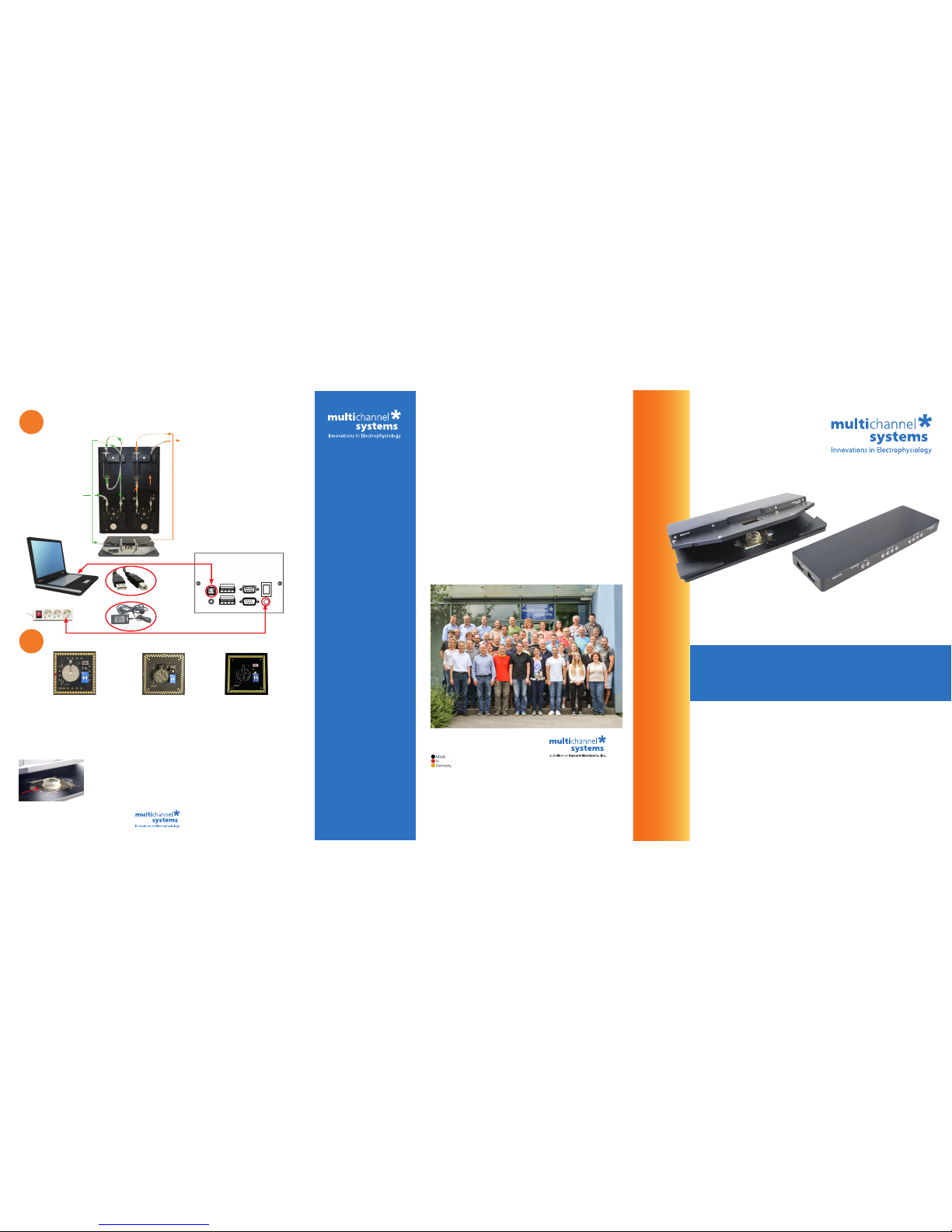
MEA Signal Generator: The 60-, 120- or 256MEA Signal Generator is used for setting up an experiment with
sample data for training, controlling, and troubleshooting purposes. Please insert the signal generator (orientation:
you can read the “ON” and “1 2” on the switch) and test your system with this articial data and make yourself
comfortable with the software settings before starting an experiment with biological samples.
You can nd the instructions for the signal generators in its bag, on the provided USB stick (Manuals/MEA_Signal_
Generator_Manual.pdf) or online at www.multichannelsystems.com/downloads/documentation.
When working with biological samples, please insert the MEAs in correct orientation.
Important: MEAs are not symmetrical! Standard MEAs with one big internal reference
electrode should be placed with the reference electrode to the left side in the headstage.
Otherwise, the MEA layout will not match with the pin layout of the channel map in the
data acquisition programs from MCS. For the orientation of special MEAs, please read
the respective datasheet. You can nd instructions for the handling of the MEAs on the
provided USB stick (Manuals/MEA_Manual.pdf) or online. Datasheets for each MEA type
are available online at www.multichannelsystems.com/products/microelectrode-arrays.
• Setting up a MEA2100-System
• For more information:
• Manuals on the provided USB stick
• www.multichannelsystems.com/
downloads/documentation
MEA2100-System: Installation Guide
© 2018
Multi Channel Systems MCS GmbH
Product information is subject to change without notice.
Products that are referred to in this document may be
either trademarks and/or registered trademarks of the
respective owners.
The publisher and the author make no
claim to these trademarks.
Multi Channel Systems
MCS GmbH
Aspenhaustraße 21
72770 Reutlingen
Germany
Phone +49-7121-909 25 25
Fax +49-7121-909 25 11
support@multichannelsystems.com
www.multichannelsystems.com
In Case You Experience any Problems
1. Consult the manuals provided on the included USB stick or online
at www.multichannelsystems.com/downloads/documentation.
2. If you do not nd help in the manuals, please do not hesitate
to contact our support team via:
- Email: support@multichannelsystems.com
- Our support form at
http://www.multichannelsystems.com/service/support.
3. In order to keep your software up-to-date and stay tuned to all
MCS news, please subscribe to our newsletter via our web site
(“Subscribe Newsletter”).
We hope that your setup was successful and you can now start your
experiments.
We wish you great progress with your research and are happy to help
you with any further questions!
Your MCS team
Test of the System and Preparation for Experiment
7
60MEA-SG
120MEA-SG
6
1. Connect the PPS2 with the power supply
unit to the power outlet.
2. Connect the PPS2 with the USB cable A-B
to the computer for PPS2 software control
(possible via an USB hub).
3. Connect the tubes of the PPS2 to the
perfusion solution, the PH01, the perfusion
out and the waste bottle. Please follow the
instructions on the leaet in the tube bag.
Adjust the ow rate.
Power Supply
Unit
USB 2.0 Cable A-B
PPS2 Rear Panel
Perfusion In
(via PH01)
Perfusion Out (from MEA)
Waste Bottle
Perfusion Solution
Connection of the Peristaltic Perfusion System PPS2
Power Outlet
USB 2.0 Port
256MEA-SG
Page 2
Connection to the Data Acquisition Computer
1. Setup and start the data acquisition computer. The data acquisition program Multi Channel
Experimenter should be installed (icon on the desktop). If the icon is not on the desktop, please
nd the Multi Channel Experimenter on the provided USB stick (Software\Multi Channel Suite\
Multi Channel Experimenter_x.x.x.exe.
2. Connect the interface board (MCS-IFB 3.0 Multiboot) with the USB super speed cable A - Micro B
to an USB 3.0 micro port of the computer. Important: Please use an USB 3.0 port (blue)!
2a: If only one headstage will be used, please use the connector labelled with USB 1
on the rear panel of the Interface Board.
2b: In case you have two headstages, use USB 2 for the second USB connection.
Do not use a hub, but connect the interface board directly to the computer!
1
2
Data Acquisition Computer
USB 3.0 Cable A-Micro B
USB 3.0 Ports
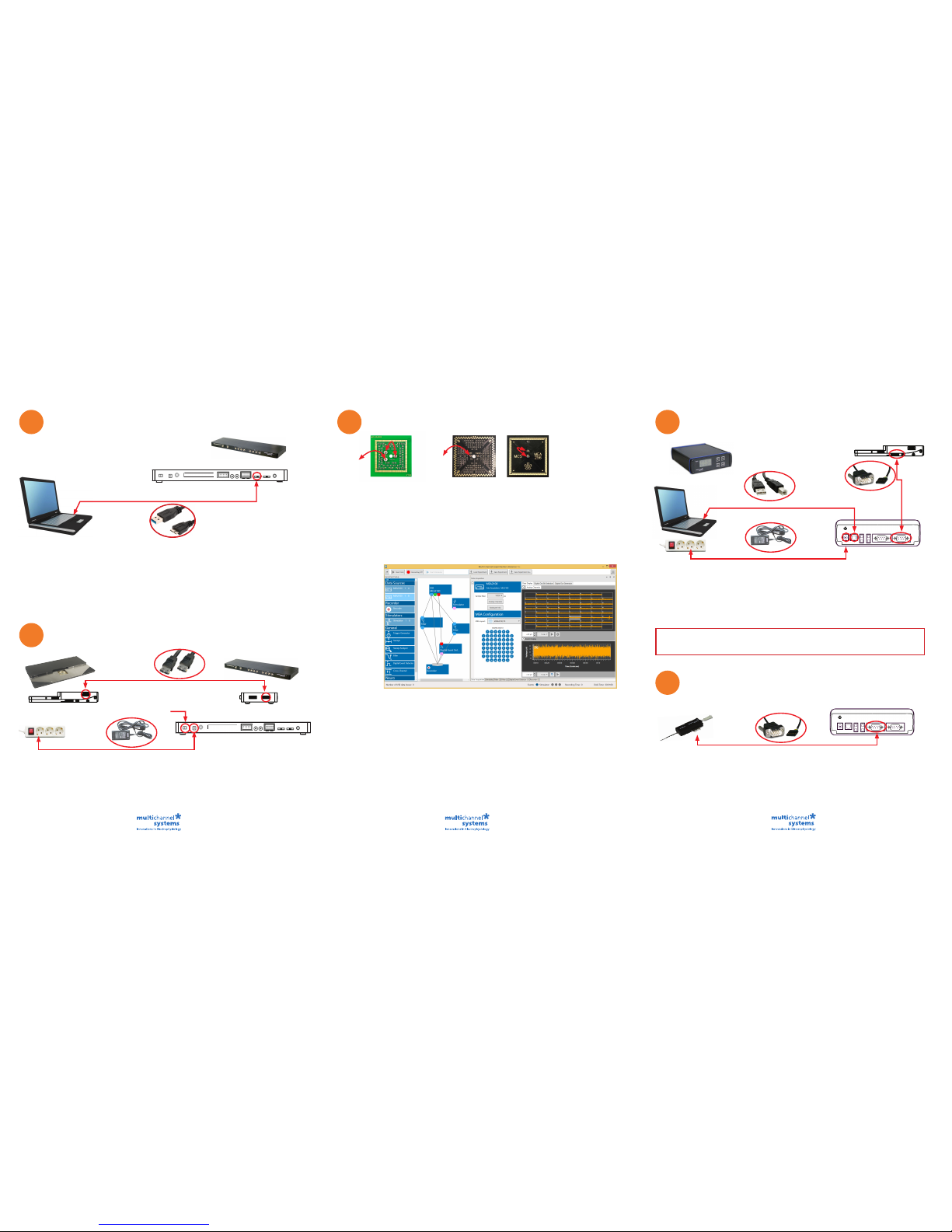
Connection of the MEA2100-System Components
Headstage
Power Outlet
Headstage Side Panel
eSATAp Cable
Power Supply Unit
Interface Board Side Panel
1. Connect the interface board to the headstage with the eSATAp cable.
1a: If only one headstage is connected, please use the connector labelled with HS1.
1b: For an optional second headstage, use the HS2 connector.
2. Connect the interface board with the power supply cable to the power outlet. Switch on the interface
board (I/O on the rear panel). If it comes up, follow the upcoming hardware installation guide.
3. For grounding, please connect the MCS interface board and the computer to the same power outlet.
HS2 HS1
4
Connection of the Temperature Controller TC02 (TC01)
Temperature
Controller TC01/02
Power Outlet
Power Supply Unit
TC01/02 Rear Panel
Headstage Side Panel
CA Cable:
D-Sub9 to Pt100
1. Connect the temperature controller with the power supply unit to the power outlet.
2. Connect the temperature controller with the CA cable (D-Sub9 to Pt100) to the headstage.
The connector is symetrical, so the orientation of the connector is irrevlevant.
3. Connect the temperature controller to the USB cable A - B to an USB 2.0 port of the computer.
If you have several temperature controllers, use the provided USB hub.
5
TC02 Rear Panel
Connection of the Perfusion Cannula PH01
Perfusion Cannula PH01
CA Cable: D-Sub9 to Pt100
1. Connect the perfusion cannula PH01 with the CA cable (D-Sub9 to Pt100) to the temperature
controller TC02. The connector is symmetrical, so the orientation of the connector is irrevlevant.
2. Set the respecitve channel of the temperature controller via control software or via touch screen
to the device PH01. Please see the TCX manual for detailed information (USB stick: Manuals/
MEA-System/TC01-02_Manual_RevG.pdf) or https://www.multichannelsystems.com/sites/
multichannelsystems.com/les/documents/manuals/TC01-TC02_Manual_RevG.pdf.
Noise Test of the System Setup via Software
Test Model Probe: The provided test model probe is used for testing the noise level of the MEA-System.
It is already inserted in your headstage and the grounding cables (black, about 5 cm) are connected.
Test-60MEA
3
USB 1 USB 2
If you ordered a MEA2100-System without perfusion, you are now done with the setup and can start
to use the devices. Please see #7 for testing and practicing with signal generators. If you ordered
a MEA2100-System with perfusion (MEA2100-60/2x60/120/256-E), please continue the setup with #5.
USB 2.0 Cable A-B
Test-120MEA
Interface Board Rear Panel
Interface Board
MCS-IFB 3.0 Multiboot
Switch ON
GND-socket in
MEA2100-HS
GND-socket in
MEA2100-HS
Multi Channel Suite Software
The Multi Channel Suite software consists of three independent software types, provided on the USB stick.
Multi Channel Experimenter is for online recording with different devices of Multi Channel Systems MCS GmbH.
Multi Channel Analyzer is for ofine analysis of les generated with the Multi Channel Experimenter online tool.
Multi Channel DataManager is for data export, enabling further analysis with Python, Matlab or other applications.
Multi Channel Experimenter Software
1. Open the Multi Channel Experimenter data acquisition software on your computer. A headstage
with two MEA slots will be indicated as MEA2100 1 A and MEA2100 1 B in “Data Sources”.
2. Move a data source and the instruments via drag and drop from the left to the right.
3. Connect the ports of the instruments via drag and drop. The ports are color coded: Electrode
raw data are symbolized in blue, analog data in green, digital data in red and feedback
events in pink ports.
4. Connect only ports with the same color. The grey port of the recorder accepts all incoming data
traces.
5. Doubleclick an instrument to open the setting parameters and the data displays in overview.
Zoom into a channel in the single view.
6. Press the “Start DAQ” button to start recording. The noise level should be between ±10 to 15 µV.
Please read the Multi Channel Experimenter_Manual.pdf on the USB stick.
7. If you experience higher noise than that, please consult the „Troubleshooting“ chapter in the
manual (MEA2100-System_Manual.pdf). Make sure that the amplier is grounded.
USB 2.0 Port
Interface Board Rear Panel
Interface Board MCS-IFB 3.0 Multiboot
Test-256MEA
Please connect
both GND-sockets
for a short circuit.
 Loading...