


Udara
INSTRUCTIONS FOR THE INSTALLER AND END USER
INSTALLATION, COMMISSIONING, MAINTENANCE AND USE OF THE APPLIANCE
Gas-fi red condensing and modulating air heater with an
automatically regulated energy-effi cient fan with a direct current
motor and gas-adaptive burner control
Brand: Multicalor Udara
Model: 10, 15, 20, 30, 40 et 50 (DF)
Land of destination: United Kingdom (UK)
Read this document before starting the installation or using the
appliance. After commissioning, give instructions to the user and
keep this document in the immediate vicinity of the appliance.
This appliance may not be operated by children, people with
a diminished mental capacity, physical impairments or lack of
knowledge unless under supervision or after receiving training
on how to use the appliance safely and as long as they are
aware of the possible risks. Children may not play with the
appliance under any circumstances. Cleaning and maintenance
performed by the user may never be carried out by children
without supervision.
Multicalor Industries NV
Blarenberglaan 21 • B–2800 Malines
Tel.: +32 15 29 03 03 • Fax: +32 15 29 03 20
info@multicalor.be • www.multicalor.be
IHL_UDARA_2016_11_04_BEGB Wijzigingen voorbehouden

Table of contents
1 Safety 5
1.1 Warnings and symbols 5
1.2 Improper use 5
1.3 General safety instructions 5
2 General information 8
2.1 Description 8
2.2 Gas category 8
2.3 Standard version 8
2.4 Outdoor air version 8
2.5 Versions 8
3 Technical data 9
3.1 In general 9
3.2 Technical data 9
3.3 Overview of components 10
3.4 Dimensions 11
4 Installation 12
4.1 In general 12
4.2 Installation of the fl ue gas outlet system 12
4.3 Installation of the condensate drain
4.4 Installation of the gas pipe 17
4.5 Installation of the ductwork 18
condffffffffffffff 17
5 Commissioning 20
5.1 Switching the appliance on and off 20
5.2 Regulating the combustion 20
5.3 Converting the appliance to propane 21
6 Operating and setting 22
6.1 In general 22
6.2 Modulating thermostat RC21 22
6.3 Air-conditioning 23
6.4 Heat pump 23
6.5 Operation in heating mode 23
6.6 Setting as ventilation 23
6.7 The control panel 23
6.8 Changing settings 24
6.9 Error codes 26
7 Maintenance 27
7.1 Maintenance by the user 27
7.2 Maintenance by the installer 27
8 Troubleshooting 28
8.1 Appliance does not start after 5 attempts 28
8.2 Internal error 29
8.3 Overheating and NTC errors 29
8.4 Display does not work 29
8.5 Flue gas fan operates continuously or not at all 29
8.6 System fan operates continuously or not at all 29
8.7 No communication with thermostat 29
8.8 Fuse or earth leakage circuit breaker intervenes 30
8.9 Loss of fl ame shortly after ignition 30
8.10 Service Request 30
8.11 Normal settings 30
2
IHL_UDARA_2016_11_04_BEGB

9 Diagram 31
10 Parts 32
10.1 Parts list 32
10.2 Ordering procedure 32
10.3 Service request 32
11 Guarantee 33
11.1 In general 33
11.2 Scope and duration of the guarantee 33
11.3 Damage that is not covered by the guarantee 33
11.4 The following are not covered by the guarantee 33
11.5 Repairs 33
11.6 Service sets 33
12 Multicalor RC21.14 34
12.1 Setting the language, date and time 34
12.2 Mode
12.3 Summer ventilation 36
12.4 Program 36
12.5 Switching off periods (max. of 2 periods) 37
13 EC Declaration of conformity 38
14 Declaration of conformity KB 2004-01-08 39
IHL_UDARA_2016_11_04_BEGB
3

4
IHL_UDARA_2016_11_04_BEGB

1 Safety
This section must be carefully studied by the installer
and the user.
1.1 Warnings and symbols
A number of symbols point out possible dangers that
may occur when installing or using the appliance.
Depending on the seriousness of the potential
situation, other symbols, icons or words are used.
Always take these warnings seriously and never ignore
them.
Danger!
This symbol warns you about a serious danger.
Intervene immediately to prevent heavy physical or
fatal injury or signifi cant material damage.
Danger!
This symbol warns about a danger or fatal injury
because of an electric shock. Ignoring this warning
can lead to signifi cant physical or fatal injury.
Warning!
This symbol warns about a dangerous situation.
Ignoring this warning can lead to physical injury,
material damage or environmental damage.
Attention!
This symbol warns about a situation that deserves
your attention. Ignoring this warning can lead to
material damage. .
Information(s)
This symbol indicates that somewhere else in the
manual you can fi nd more information about this
topic or it will refer you to a local standard.
1.2 Improper use
The Udara air heater is intended for heating systems
based on hot air where both the heated and the intake
air is distributed through a system of ducts.
If the appliance is used inexpertly or improperly, a
situation may be created that entails danger for the
user or third parties or can lead to damage to the
appliance or the environment.
You may only install the Udara if you combine the
appliance with the accessories listed in the manual for
the combustion air supply (CAS) and fl ue gas outlet
(FGO).
As an installer or user you have the obligation to
closely follow the instructions contained in the manual
of the appliance or the possible accessories. You
must, moreover, respect all inspection and
maintenance conditions
You must connect the appliance electrically in
accordance with the protection degree specifi ed on
the nameplate and in accordance with the locally
applicable regulations.
If you implement changes to the appliance that are
not described in the manual, you must ask for written
permission from the manufacturer.
Transgressions to these instructions will be deemed
not according to the regulations and may lead to
dangerous situations or material damage regarding
which the manufacturer rejects any responsibility.
1.3 General safety instructions
The installation, mounting, disassembly,
commissioning, maintenance and repair must only be
performed by professionals. They must have all legal
qualifi cations and, by preference, they must have
followed training at the manufacturer of the appliance.
As a user, you must closely follow the maintenance
instructions. Ask your installer to go through this
section if you have any questions.
1.3.1 Danger of fatal injury because of gas leaks
With regard to gas smells in buildings:
• extinguish all naked fl ames (such as from
smoking, cookers, etc.).
• Do not operate any doorbells, switches, plugs,
telephones, entry panels or other devices
• Close the main gas valve and the gas valve on the
product.
• Open windows and doors.
• Evacuate the building and stop third parties from
entering the building.
• Warn the fi re brigade using a telephone
connection outside the building (for example, at
the neighbours).
• If the leak occurs in front of the gas meter, warn
the energy company.
Liquid gas is heavier than air and will collect near the
fl oor. If the appliance is being installed below ground
level, leaking liquid gas will collect and, therefore,
there will be an explosion risk.
• Ensure that liquid gas can never escape from the
appliance or the gas pipe.
1.3.2 Danger of fatal injury because of fl ammable
substances
Do not use or keep explosive or fl ammable substances
(petrol, thinner, paper, etc.) near the appliance.
1.3.3 Danger of fatal injury because of
combustion gases escaping
If fl ue gases escape, this can lead to dangerous
situations.
• Only use the appliance with a fully installed
CAS/FGO
IHL_UDARA_2016_11_04_BEGB
5

• Always use the appliance with an installed front
cover.
A dangerous situation may occur if the appliance is
supplied with insuffi cient combustion air.
• Ensure there is a permanent and unobstructed
air supply to the set-up room of the appliance in
accordance with the applicable standards.
If you smell fl ue gases or you suspect there is a
combustion gas leak, you must intervene immediately.
• Open windows and doors and ventilate the
building.
• Switch off the product.
• Consult your installer and have the combustion
circuit checked for leaks or obstructions.
If the condensate trap is empty, fl ue gas may leak.
• Always use the appliance with a fully fi lled
condensate trap.
1.3.4 Danger of fatal injury because of electric
shocks
If you touch components that carry a current, there is
a danger of fatal injury because of an electric shock.
Before you work on the product:
• Ensure that the current to the appliance has been
disconnected.
• Protect against reconnection.
• Always wait a few minutes so that the capacitors in
motor controls, etc., are discharged.
1.3.5 Danger of fatal injury because of changes
Unauthorised changes to the product or set-up room
can lead to dangerous situations.
• Never remove, bypass or change the temperature
probes in the appliance.
• Sealed parts in the appliance must not be opened.
• Never change the piping for gas or the CAS/FGO
and the wiring for the voltage.
• The condensate discharge must always be
present and changes must never be implemented
regarding the condensate discharge.
1.3.6 Danger of fi re or becoming trapped
If you want to connect the appliance without ductwork,
you must:
• Install a vent on the suction opening that impedes
access to the fan compartment;
• Install a vent or blow plenum on the blow hole so
that there is no direct access to the heat
exchanger compartment. This vent or plenum
must also ensure that fl ammable material cannot
fall on the heat exchanger.
These accessories are available from our range. If you
do not know which accessories you need, you can
contact your dealer for additional information.
Some parts of the appliance can become very hot
during and shortly after use.
• Only carry out activities such as maintenance after
the appliance has completely cooled down.
1.3.7 Risk of corrosion damage
Chemical products such as solvents, paints,
adhesives, soaps, etc., may lead to corrosion in the air
heater or in the CAS/FGO.
• Ensure that the combustion air is always dust-free
and is not polluted by fl uorine, chlorine, sulphur
and other contaminants.
• If the combustion air is being supplied through a
chimney duct, it must not have been used in the
past as an FGO for fuel oil devices, coal or wood
burners or open fi replaces.
• If the appliance is set up in launderettes, ironing
parlours, swimming pool rooms, etc., the
appliance must be installed in a separate
set-up room in which the ambient air is free from
chemical contaminants.
• Combustion air that is insuffi ciently dust-free
can lead to an unreliable ignition and, in extreme
cases, even damage to the heat exchanger
because of internal dirt. If this risk exists, you must
order an intake fi lter for the CAS that is available
as an accessory.
1.3.8 Material damage because of unsuitable
tools
In addition to conventional tools, you also need a
number of specifi c tools to work on or maintain the
Udara appliance.
• You need a special square drill bit, size 2, to
loosen the tapping screws.
• In addition, you need a set of Allen wrenches with
a rounded side.
• Using a 0-10 Nm torque wrench is recommended.
• You must have a fl ue gas analysing device that
can measure the following substances in the fl ue
gases: NOx (nitrogen oxides), O2 (residual
oxygen) and CO (carbon monoxide). If your
appliance cannot measure NOx, it is strictly
prohibited to change the adjustment of the
appliance or to perform a manual calibration.
1.3.9 Material damage because of frost
If the appliance is not set up frost-free, the appliance
can be damaged. If the temperature of the suctioned
air drops far below freezing point, frost can even occur
in the heat exchanger itself.
In such a case, a bypass must be made using the air
outlet duct to the suction duct so that the suctioned air
is preheated.
• Also make absolutely sure that the environment in
which the appliance is being installed cannot lead
to any dangers because of fl oating dust and/or
fl ammable or corrosive substances or fumes.
6
IHL_UDARA_2016_11_04_BEGB

1.3.10 Material damage to the fl exible gas tube
The fl exible gas tube can be damaged because of a
heavy load due to a weight or repeated and
unnecessary bending.
• Do not suspend the burner and mixing box from
the fl exible corrugated gas tube during
maintenance
1.3.11 Material damage after water ingress
If the appliance or parts of it are exposed to water
ingress, the appliance must be put out of service
immediately. All safety components that are exposed
to water must, subsequently, be replaced
IHL_UDARA_2016_11_04_BEGB
7

2 General information
2.1 Description
Multicalor Udara air heaters are gas-fi red condensing
and modulating appliances with a cleaner combustion,
automatically controlled direct current fans and a
gas-adaptive control.
2.2 Gas category
The appliance has been set for being fi red with natural
gas of the second family (I2N) ex-factory. If you want
to use the appliance with propane, the burner
management control system must be adjusted and a
new nameplate must be added to the appliance. Only
an engineer appointed by the manufacture can do this.
The appliance is delivered ready for use. It is
suffi cient to connect the fl ue gas outlet (FGO) duct,
the combustion air supply (CAS) duct, the gas pipe,
the condensate discharge, the air ducts and the power
lines.
2.3 Standard version
The standard version of the appliance is used for the
distribution of recycled air to which no more than 25%
of outdoor air is added or for the distribution of outdoor
air to heat recovery. The appliance will work in this
mode ex-factory.
2.5.1 Upfl ow
Suctioning takes place at the bottom of the appliance
with regard to an upfl ow version. The blowing out of
the hot air takes place at the top of the appliance. This
is also sometimes called a top blowing version.
The fi lter is at the bottom of the air heater as standard.
If you want to connect the appliance on its side, you
must order an optional fi lter frame.
If side connection is required, we recommend ordering
a long tool life fi lter from the accessory range and not
to opt for the standard side fi lter frame with regard to
the Udara 40 and 50.
2.5.2 Downfl ow
Suctioning takes place at the top of the appliance with
regard to a downfl ow appliance. The blowing out of the
hot air takes place at the bottom of the appliance. This
is also sometimes called a bottom blowing version.
DF is added to the appliance type with regard to the
downfl ow version.
2.4 Outdoor air version
The outdoor air version of the appliance is used to
distribute air to which more than 25% of outdoor air is
added.
Warning!
If the appliance is deployed as an outdoor air
version, you must perform the changes specifi ed
below to prevent damaging the appliance.
If you want to deploy the appliance as an outdoor air
appliance, you must order an additional insulation
set to insulate the fan compartment of the Udara air
heater. This will limit condensation on the outer
housing of the appliance.
In addition, the condensate trap must be installed
outside the appliance using an extended hose set with
regard to the upfl ow versions of the Udara.
The condensate hoses in the fan compartment must
also be safeguarded from frost, for example, by
installing thermal insulation and/or a heating ribbon
around the hoses.
If the temperature of the suctioned air drops below
freezing point, the condensate in the heat exchanger
itself can freeze. In such a case, a bypass must be
made using the air outlet duct to the suction duct so
that the suctioned air is preheated. 2
2.5 Versions
The Multicalor Udara appliances are available in 2
versions: upfl ow and downfl ow.
8
IHL_UDARA_2016_11_04_BEGB
3 Technical data
3.1 In general
The Udara air heaters are CE approved by Technigas based in Brussels and comply with the Gas Appliance
Directive 2009/142/EC. The CE label added to every appliance is the guarantee that the appliances are
continuously checked by TECHNIGAS. The appliances also meet the Machinery Directive 2006/42/EC, the
EMC Directive 2004/108/EC, the Low Voltage Directive 2006/95/EC and the Hazardous Substances Directive
2011/65/EU.
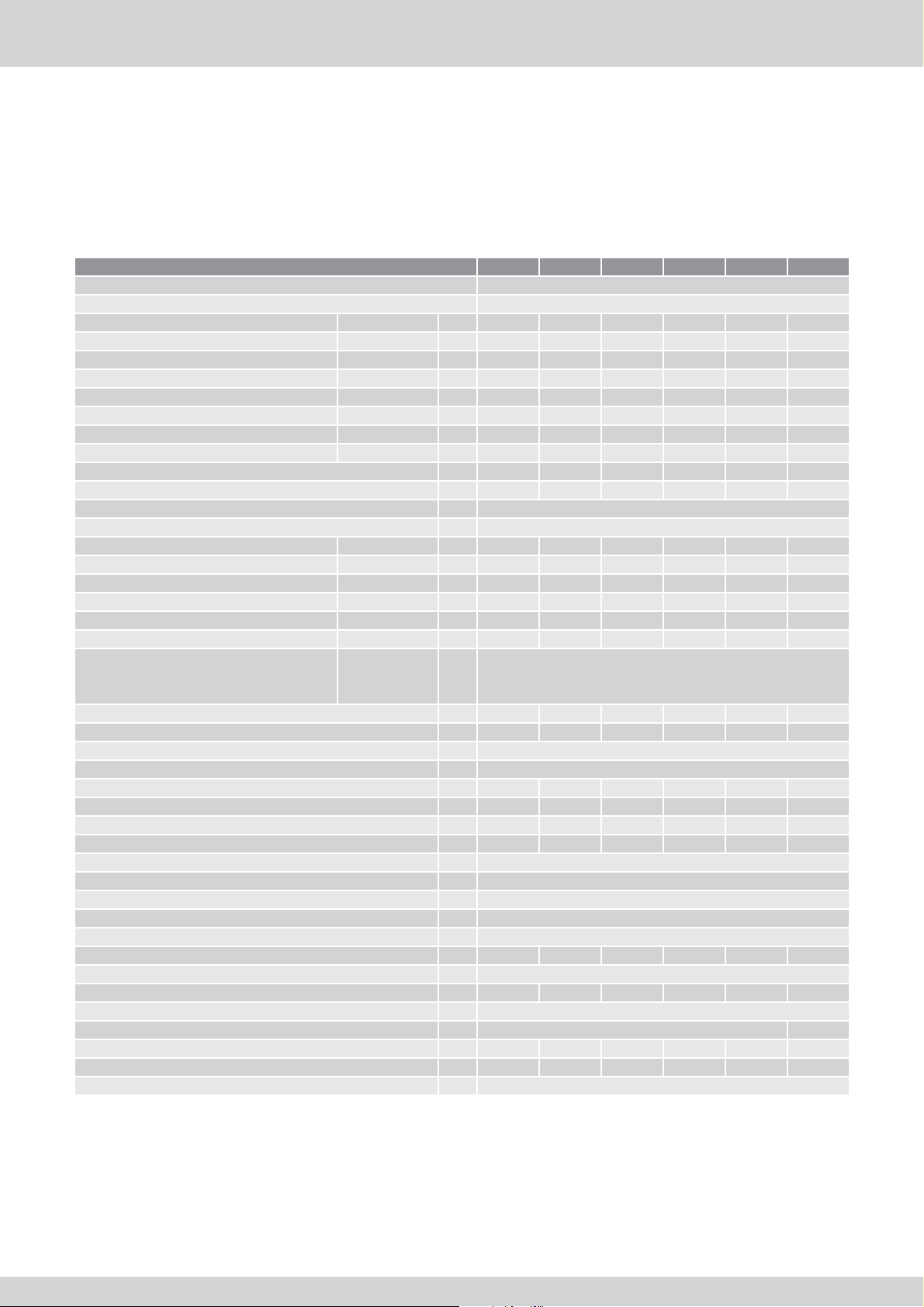
3.2 Technical data
3.2.1 Gas category I2N and I3P technical data
Udara HR (DF) 10 15 20 30 40 50
Gas category I2H, I2L, I2N, I2E, I3P
Gas appliance types B22p, C12, C32, C52, C92
Maximum load on the lower value [PCI] G20 - 20 mbar kW 10.0 14.8 19.7 29.5 39.4 49.2
Minimum load on the lower value [PCI] G20 - 20 mbar kW 1.8 2.6 3.4 5.1 6.8 8.6
Maximum power G20 - 20 mbar kW 10.6 15.7 21.0 31.4 42.1 52.5
Minimum power G20 - 20 mbar kW 2.0 2.8 3.7 5.6 7.4 9.4
Gas consumption at full load G20 - 20 mbar m³/h 1.058 1.566 2.085 3.122 4.169 5.206
Gas consumption at partial load G20 - 20 mbar m³/h 0.190 0.275 0.360 0.540 0.720 0.910
Gas consumption at full load G25 - 25 mbar m³/h 1.253 1.854 2.468 3.695 4.935 6.163
Gas consumption at partial load G25 - 25 mbar m³/h 0.216 0.313 0.409 0.614 0.818 1.035
Thermal effi ciency at full load % 106.2 106.3 106.4 106.6 106.8 106.8
Thermal effi ciency at partial load % 109.0 109.0 109.0 109.0 109.0 109.0
NOx emissions < 30 mg / kWh (CLASS 5 EN1020 / EN1319)
Gas category I3P
Maximum load on the lower value [PCI] G31 - 37 mbar kW 10.2 15.1 20.1 30.1 40.2 50.2
Minimum load on the lower value [PCI] G31 - 37 mbar kW 1.7 2.4 3.2 4.8 6.3 8.0
Maximum power G31 - 37 mbar kW 10.5 15.6 20.7 31.1 41.6 52.0
Minimum power G31 - 37 mbar kW 1.8 2.6 3.4 5.0 6.7 8.5
Gas consumption at full load G31 - 37 mbar kW 0.417 0.617 0.822 1.231 1.644 2.053
Gas consumption at partial load G31 - 37 mbar kW 0.069 0.099 0.13 0.195 0.260 0.328
G20
Inlet pressure
Nominal air fl ow rate m³/h 650 1200 1500 2100 3000 3500
Nominal temperature increase °C 51 41 44 47 44 47
Maximum discharge air temperatur °C 80
Working temperature in heating mode °C minimale 0° / maximale 35°
Nominal taken up power kW 0.17 0.20 0.26 0.30 0.55 0.60
Diameter restriction mm 3.6 4.0 4.0 4.4 6.0 6.4
Mixing box # 45 45 30 30 10 0
Venturi # 4 4 5 8 6 6
Gas connection Ø 1/2” G
FGO diameter mm 80
CAS diameter mm 80
Protection degree IP 20
Condensate discharge diameter mm 32
Condensate quantity kg/h 1.3 2.0 2.6 3.9 5.2 6.5
Power supply voltage V 230 V - 50 Hz (N + L + PE)
Width mm 400 400 400 500 600 700
Depth mm 720
Height mm 1100 1200
Weight kg 52 66 71 84 99 122
Fuse (outside appliance) A 6T 8T 8T 16T 16T 16T
CE approval number # E1432/5671
G25
G31
mbar
20
25
37
IHL_UDARA_2016_11_04_BEGB
9

3.3 Overview of components
1
16
1
2 3
4
5
6
7
8
13
9
10
11
12
14
2 3
15
5
4
6
11
12
9
10
15
16
Legend
Number Meaning
1 Combustion air supply
2 Flue gas outlet
3 Control panel
4 Probe discharge air temperature (NTC 2 / NTC 5)
5 Flue gas outlet coupling
6 Mixing box and venturi
7 Ionisation electrode
8 Ignition electrode
9 Flexible gas tube
10 Burner management control system
11 Flue gas fan
12 Gas valve
13 Intake temperature probe (NTC 1)
14 Condensate discharge trap
15 System fan
16 Air fi lter (in downfl ow in fi lter cabinet)
14
7
8
4
10
IHL_UDARA_2016_11_04_BEGB
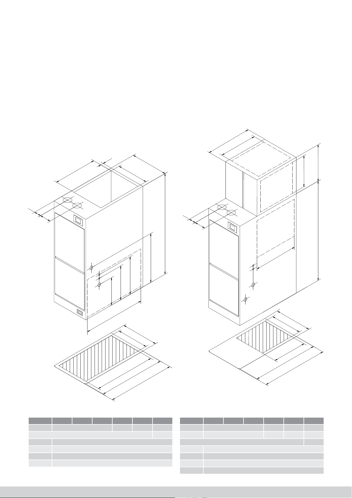
3.4 Dimensions
3.4.1 Dimensions Upfl ow
0
7
4
7
5
1
2
0
3.4.1 Dimensions Downfl ow
515
400
0
3
A
A
-
6
0
7
*
0
0
11
5
1
2
0
B-40
B
0
0
11
*
35
5
0*
1
4
*
0
*
37
00
3
0
1
4
x
5
7
6
A
A
-
6
0
0
6
6
0
2
7
5
2
7
Legend
Udara 10 15 20 30 40 50
A 400 500 600 700
* + 70
a Gas throughput
b Power supply cable connection
c Thermostat connection
d Condensate drain throughput
0
1
4
x
0
7
4
A
A
-
6
0
0
0
4
0
2
7
5
2
7
Legend
Udara 10 15 20 30 40 50
A 400 500 600 700
B 340 440 540 540
* + 70
a Gas throughput
b Power supply cable connection
c Thermostat connection
d Condensate drain throughput
IHL_UDARA_2016_11_04_BEGB
11
4 Installation
4.1 Algemeen
4.1 In general
Gevaar!
Alvorens over te gaan tot installatie of inbedrijfname
Danger!
van het toestel:
Before installing or commissioning the appliance:
• Verzeker u er van dat de condities van het lo-
• Make sure that the conditions of the local
kale distributienet (gas en elektriciteit) overeen-
distribution mains (gas and power) match the
stemmen met de afstelling van het apparaat.
adjustment of the appliance.
• Controleer of het land van bestemming
• Check whether the country of destination is
vermeld op verpakking en kentekenplaat
specifi ed on the packaging and the nameplate
overeenstemt met het land waar u het toestel
matches the country where you are installing
installeert.
the appliance (BE = Belgium).
(BE = België).
• Check whether the selected CAS/FGO method
• Controleer of de gekozen manier van VLT/RGA
is specifi ed on the nameplate.
Contact us if this is not the case and immediately
vermeld staat op het kentekenplaatje.
stop the installation or commissioning.
Contacteer ons indien dit niet het geval is en stop
ogenblikkelijk de installatie of inbedrijfname.
Waarschuwing!
De luchtverwarmer mag uitsluiten geïnstalleerd
Warning!
worden door een bevoegd installateur die over alle
The air heater must only be installed by a comwettelijk vereiste certifi caten beschikt.
petent installer who has all the legally required
certifi cates.
Lokale normen
De installatie moet worden uitgevoerd conform met
Local standards
de laatste uitgave van alle lokale normen en met de
The installation must be performed in accordance
installatiehandleiding van het toestel.
with the latest publication of all local standards and
Raadpleeg zeker de NBN B 61-001, NBN B 61-002,
the installation manual of the appliance.
NBN D 51-003, NBN D51-004, NBN D 51-006,
Ensure you consult the NBN B 61-001,
NBN D 30-003
NBN B 61-002, NBN D 51-003, NBN D 51-004,
NBN D 51-006, NBN D 30-003.
4.1.1 Transportschade
Gelieve bij levering de luchtverwarmer op transport-
4.1.1 Damage during transport
schade na te kijken. Indien schade wordt vastgesteld,
Check the air heater for damage during transport upon
vermeldt u dit op de vrachtbrief en waarschuwt u
delivery. If damage is established, specify this on the
schriftelijk uw leverancier.
consignment note and warn your supplier in writing.
4.1.2 Verpakking
4.1.2 Packaging
De luchtverwarmers zijn verpakt in een doos uit gere-
The air heaters are packaged in a box made of
cycleerd karton. Werp de verpakking niet weg maar
recycled cardboard. Do not throw away the packaging,
biedt ze aan voor verdere recyclage.
but again offer it for recycling.
4.1.3 Minimale vrije ruimte rondom het toestel
4.1.3 Minimum free space around the appliance
Let op volgende minimale vrije ruimten bij de opstelling
Ensure that the following minimum free space is
van het toestel:
available when setting up the appliance:
• Rondom het toestel 50 mm vrijhouden.
• keep 50 mm free around the appliance;
• Rondom de rookgasafvoer en eventueel brand-
• keep at least 25 mm free space around the fl ue
baar materiaal minimum 25 mm vrijhouden; bij
gas outlet and possible fl ammable material; free
concentrische rookgasafvoer dient geen vrije
space is not required with regard to a concentric
ruimte te worden gerespecteerd.
fl ue gas outlet;
• Aan de voorzijde van het toestel dient ongeveer
• approximately 1000 mm of service space must be
1000 mm service ruimte voorzien te zijn (let op
available at the front side of the appliance (ensure
een comfortabele stahoogte).
that there is a comfortable standing height);
• Aan de kant van de condensafvoer dient minimaal
• at least 200 mm of free space must be available
een vrije ruimte aanwezig te zijn van 200 mm.
on the side of the condensate discharge.
•
4.1.4 Set-up room
Pay attention to the following guidelines when
determining the place to set up the air heater:
• Position the appliance as closely as possible to
the fl ue gas outlet and the combustion air ducts.
• Position the appliance centrally in comparison to
the ductwork.
• Position the appliance on a level and robust
substrate.
• The appliance must be raised on a wet fl oor.
• Always set up the appliance isolated from the
structural structure to prevent the transmission of
noise and vibrations.
Danger!
• When using an open return, no appliances with
an open combustion chamber may be present
in the same set-up room. Strictly respect local
standards with regard to the ventilation of the
set-up room.
Attention!
The appliance must be level!
The appliance must be set up frost-free.
4.1.5 Moving the appliance on site
The air heaters must never be moved using the corners by tilting the appliance. The housing of the appliance can be irrevocably damaged due to this. This
damage is not covered by the appliance’s guarantee.
4.2 Installation of the fl ue gas outlet
system
4.2.1 Luchttoevoer– en rookgasafvoerleidingen
Danger!
• Protect the fl ue gas outlet with a non-fl amma-
ble sheath if it is being guided through walls or
cavities made of fl ammable material. Always
respect the free space of 25 mm between this
sheath and the discharge pipe.
• Every Udara appliance must be equipped with
an individual FGO/CAS. Shared discharge
systems are not permitted.
• The burner compartment of the Udara is part of
the combustion circuit. The appliance must not
be put into operation with a missing front cover.
Information(s)
In some countries, the use of CAS or FGO pipes
that have not been enclosed in metal or other fi re-
retardant material is prohibited. Always consult the
local standards before installing.
Udara air heaters are appliances that, by preference,
are set up as a closed appliance (type C). This means
that the appliance must be connected through a parallel or concentric fl ue gas outlet (FGO) and combustion
air supply (CAS).
Combustion gases are discharged through one pipe
and air required for the combustion is supplied through
the other pipe.
12
IHL_UDARA_2016_11_04_BEGB

You can also set up the appliance as an open one
(type B). If the appliance is set up as B22p, a special
air fi lter must be installed on the suction inlet of the
Udara air heater. This fi lter will stop the igniter ducts
between the premix burners from becoming
obstructed and will prevent individual objects from
falling into the appliance.
Always position measuring points in the FGO and
CAS so that a representative sample of the fl ue gases
and the combustion air can be taken. The measuring
points must, by preference, be positioned as close as
possible to the appliance.
The used CAS and FGO pipes must be gas-tight and
must meet the applicable standards. Multicalor has
PP and stainless steel pipes in its range that meet all
applicable standards. If the discharge of the
combustion gases and supply of combustion air takes
place through the roof, the especially designed and
approved icicle-low roof gland MUGRO SKYLINE
must be used.
Les conduites utilisées pour l’évacuation des gaz de
fumée et l’alimentation en air de combustion doivent
être étanches aux gaz et respecter les normes en
vigueur. Dans sa gamme, Multicalor possède des
conduites en PP et en inox qui respectent toutes les
normes en vigueur.
4.2.1 Type B22p connection
The combustion air is taken from the room with regard
to a type B22p connection. The discharge takes place
through a gas-tight fi xed or fl exible pipe.
L
2
3
1
Connecting to another roof gland is not permitted in
relation to the approval in accordance with the Gas
Appliance Directive. If the discharge of
combustion gases and the supply of combustion air
takes place through the wall, the especially
designed and approved wall gland MUGRO WALL
must be used. Connecting to another wall gland is not
permitted in relation to the approval in accordance with
the Gas Appliance Directive.
The fl ue gas outlet must be installed with a minimum
slope of 5 cm/m towards the appliance so that the
condensate can fl ow towards the appliance.
Legend
Number Meaning
1 Measuring point
2 Combustion air supply opening
3 Intake fi lter (dusty rooms) or protective vent
There must always be a direct and non-closable air
supply outlet towards the outside with an area of 3
cm²/kW as the total set up power with a minimum of
150 cm². If local standards prescribe stricter requirements, you must, of course, comply with these.
Position a protective vent or, when setting up the
appliance in dusty rooms, an intake fi lter on the CAS
so that no individual objects can fall into the appliance
and the burner is safeguarded from contaminants.
Always position a measuring point in the FGO. The
maximum allowable length for the discharge pipe is
specifi ed in table 4.2.7.
Danger!
Never connect an Udara appliance straight on to a
standard chimney! A gas-tight FGO must always be
used.
IHL_UDARA_2016_11_04_BEGB
13
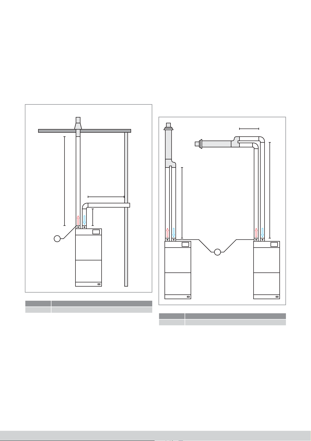
4.2.2 C52 two-pipe system
As an alternative to open fl ue gas outlet system B22p,
you can also use closed system C52.
The drawing below shows a two-pipe C52 system.
4.2.3 Parallel systems (C12/C32)
You can use a parallel system to discharge the fl ue
gases. Multicalor carries a range of supply and
discharge pipes made of high-quality PP and stainless
steel.
The length of the fl ue gas outlet (L1+L2+L3) plus the
equivalent length of the bends must not exceed the
maximum value specifi ed in item 4.2.7.
Always install a measuring point in the CAS and FGO.
L1
L2
L3
The drawing below shows a parallel system.
The length of the fl ue gas outlet plus the equivalent
length of the bends must not exceed the maximum
value specifi ed in item 4.2.7.
Always install a measuring point in the CAS and FGO.
L2
L1
L
1
Legend
Number Meaning
1 Measuring point
1
Legend
Number Meaning
1 Measuring point
14
IHL_UDARA_2016_11_04_BEGB

4.2.4 Concentric systems (C12/C32)
The fl ue gas outlet (FGO) pipe is surrounded by the
combustion air supply (CAS) pipe with regard to a
concentric fl ue gas outlet system. Multicalor carries a
full range of concentric pipes.
The Y-pipe supplied with the fl ue gas outlet terminal
must be positioned on top of the appliance with regard
to a concentric connection.
Always position a measuring point in the concentric
piping, by preference, immediately after the Y-pipe or,
if this is not possible, as close as possible to the
appliance.
L2
4.2.5 Chimney renovation (C92)
It is sometimes interesting to install a special fl exible
fl ue gas outlet pipe with a diameter of 80 mm in an
existing fl ue gas outlet (conventional) fi replace. The
combustion air can then be supplied through the air
cavity between the fl ue gas outlet pipe and the existing
chimney or in the room itself. The connection between
the fl exible pipe in the old fl ue gas duct and the
appliance can then take place in parallel or
concentrically.
L2
L1
L
1
Legend
Number Meaning
1 Measuring point
The length of the fl ue gas outlet plus the equivalent
length of the bends must not exceed the maximum
value specifi ed in item 4.2.7.
L1L3
1
Legend
Number Meaning
1 Measuring point
The length of the fl ue gas outlet plus the equivalent
length of the bends must not exceed the maximum
value specifi ed in item 4.2.7.
Warning!
Do not use the old fl ues as combustion air supply if
they have been used in the past as the FGO for fuel
oil appliances, coal or wood burners or fi replaces.
IHL_UDARA_2016_11_04_BEGB
If you want to use this system, the existing fi replace
must at least measure 150 mm x 150 mm when using
a discharge pipe with a diameter of 80 mm.
15

4.2.6 Maximum length of the fl ue gas outlet
The maximum length is the sum of the following: the
length of the straight pipes (L, L1 + L2, or L1+L2+L3 in
Warning!
The maximum allowed length of the fl ue gas outlet
must not be exceeded.
the fi gures)/ the equivalent length of the other
elements such as bends or intake fi lters that you can
fi nd in the table below.
Depending on the used fl ue gas outlet and appliance
types, the maximum length of the fl ue gas outlet and
combustion air supply vary.
Table 2: Maximum allowed length of the fl ue gas outlet
Type Ø Remarks Maximum allowed length
Udara HR (DF) 10 15 20 30 40 50
B22P
C52
C12
C32
C12
C32
C92 80/125 mmConcentric pipes dans la chaufferie
80 mm Smooth pipes in PP/RVS
Flexible pipes MG Flexline in the fl ue gas outlet
80/125 mmConcentric systems with wall terminal
Concentric systems with roof terminal
80 + 80 mmParallell systems with wall terminal
Parallell systems with roof terminal
30 30 30 30 30 20
12.5 12.5 12.5 12.5 12.5 10
20 20 20 20 20 15
12.5 12.5 12.5 12.5 12.5 10
Flexible pipes MG Flexline in the fl ue gas outlet
Bend 90° Bend 90° 2.00
Bend 45° Bend 45° 1.00
Bend 30° Bend 30° 0.75
Intake fi lter 4.00
Protective vent 1.00
4.2.7 Allowed materials
Attention!
Never use fl ue gas outlet or combustion air supply
piping made of PVC. Do not use aluminium for the
fl ue gas outlet either.
You can use PP pipes as fl ue gas outlet pipes if local
standards allow this. If not, use gas-tight pipes made
of stainless steel of the 40, 50, 60 or 70 type in accordance with the EN 1856-1 standard.
You can use PP pipes as combustion air supply pipes
if local standards allow this. If not, use gas-tight pipes
made of stainless steel of the 40, 50, 60 or 70 type in
accordance with the EN 1856-1 standard.
4.2.8 Position of the terminal
All applicable standards must be respected with regard
to wind attack and pollution. If local standards are not
available, use the following guidelines:
• Every terminal must be located in a square of 0.6
m without obstacles.
• The distance between a roof terminal and a
vertical wall must at least be 0.5 m.
• The distance between a roof terminal and a wall
that makes an angle with it and in which windows
can be found must at least be 2.5 m.
• The distance between 2 roof or wall terminals
must at least be 0.6 m.
• The terminals of 2 end pieces that are one on top
of the other in a wall must at least be 2.5 m
• Terminals may not be installed under a porch roof.
• The terminal must at least be at a distance of 1.0
m from the plot border.
• The wall terminal must at least be 1.0 m above
ground level and the roof terminal must at least be
0.4 m above the roof (in connection with snow).
• The wall terminal must at least be at a distance of
0.5 m from the corner of the building.
16
IHL_UDARA_2016_11_04_BEGB
4.3 Installation of the condensate drain
condffffffffffffff
Warnings!
• NEVER shut off the condensate discharge.
• NEVER remove the trap and do not make
any unauthorised changes to the condensate
discharge.
• Do not discharge the condensate directly
outside (frost risk), but discharge the water
using the indoor drainage system.
• If local standards require condensate neutralisation, you must install such a device before
discharging the condensate down the drain.
• The condensate drain MUST be installed with
a slope (5 cm/m) towards the drainage system.
• The trap must be installed outside the fan compartment and hoses must be safeguarded from
frost with regard to an outdoor air appliance.
• The trap must be installed outside the fan compartment and hoses must be safeguarded from
frost with regard to an outdoor air appliance
d’égout normal en PVC ou PE convient bien.
• The trap must be installed outside the fan compartment and hoses must be safeguarded from
frost with regard to an outdoor air appliance
• After installation or maintenance, clean both
traps and fi ll with clean water.
4.4 Installation of the gas pipe
Danger!
• The installation of the gas pipe must only be
carried out by a certifi ed installer or energy
company.
• Check whether the gas category and inlet
pressure match the data on the appliance’s
nameplate.
• Only use fi ttings and pipes that have been
specifi cally approved for gas systems.
• Always consult local standards before installing
the gas pipe.
• Always position an approved stop cock in front
of the appliance. NEVER use a fl ame to check
the piping or to trace a leak.
Attention!
• Ensure there is no dirt in the gas pipe. Purge
the piping before installation using nitrogen to
clean them.
• By preference, install an additional gas fi lter to
prevent contamination of the gas control block.
• Pay attention when using leak sprays near
electrical components.
• Close the stop cock and disconnect the gas
valve when pressure testing the gas pipe. The
maximum pressure when pressure testing is
125 mbar.
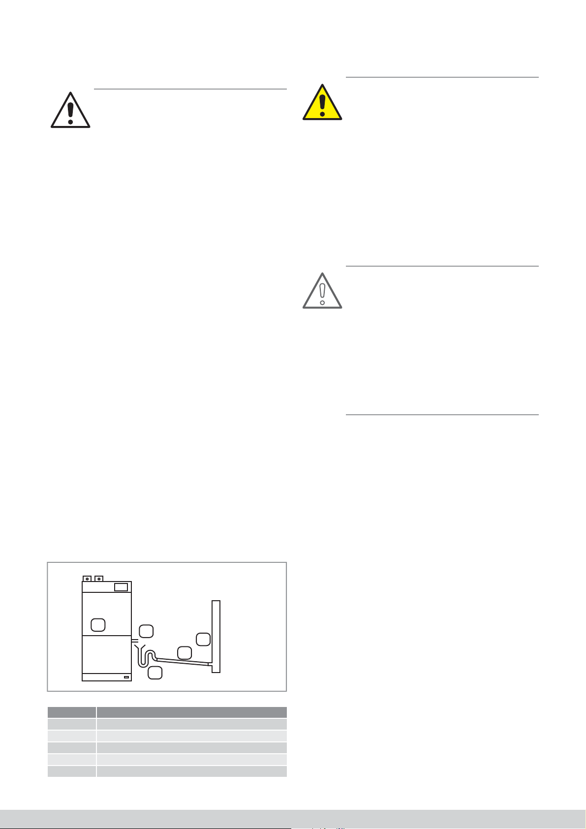
Voor een juiste werking van het toestel dient de
To ensure the appliance operates correctly, the
condensafl oop op de riolering aangesloten te worden.
condensate drain must be connected to the drainage
Standaard is de aansluiting rechts voorzien. Indien
system. The connection is provided on the right as
gewenst kan de condensafl oop ook links gebeuren. U
standard. If required, the condensate drain can also be
dient dan de blinde tule, die het gat in de linkerzijde
placed on the left. You must then move the blind
afsluit, naar de rechterzijde te verplaatsen.
grommet that seals the hole on the left side to the right
side. If you move the trap to the left side, you may
Indien u de sifon naar de linkerzijde verplaatst, dient
have to shorten the discharge hoses. You can do this
u mogelijk de afvoerslangen in te korten. Dit kan met
with a sharp knife. Always connect the condensate
een scherp mes gebeuren. Sluit de condensafl oop
drain in accordance with the enclosed drawing.
steeds aan volgens de bijgevoegde tekening.
1
2
5
4
3
Legend
Number Meaning
1 Appliance
2 Funnel
3 Extra trap
4 Gradient on slope (5 cm/m)
5 Indoor drainage
The area of the gas pipe must be in accordance with
all applicable local standards and regulations. If the
area is too small, the appliance will not be able to
achieve its maximum power and starting problems can
occur.
Connect the gas supply piping using a ½” connection
directly on to a 90° bend that has been equipped with
a gas control block ex-factory.
Position an approved shut-off valve immediately in
front of the appliance. The feed for the gas connection
is provided on the right as standard.
If required, the gas connection can also be on the left.
Blind grommets in the openings ensure there is an
airtight seal of the burner compartment.
IHL_UDARA_2016_11_04_BEGB
17

4.5 Elektrische installatieDanger!
• Ensure that the installation is free from voltage
(dead) before you start the installation.
• Always connect the earthing.
• Respect all applicable standards (for example,
AREI (General Regulations on electrical installations)).
• Always position an external isolator switch at
the appliance that will allow you to isolate the
appliance from the mains.
• The minimum creepage distance between
contacts must be 3 mm.
The electrical installation must always be carried out
in accordance with the last publication of the relevant
standards and the regulations of the local energy
company.
4.4.1 Connecting the power supply
A 3-pole terminal has been installed in the fan
compartment where a supplied plug can be installed
for the mains power supply. A hole has been included
in the housing to lead through the cable.
Use the supplied blind grommet or cable coupling to
lead through the cable.
Connect the cable to the 230 V~AC power supply with
earthing.
We recommend connecting the appliance directly to
the distribution box that has a delay fuse (the value to
be used is specifi ed in the technical data table).
Attention!
We recommend using circuit breakers with a D
switching-off curve because of the high input surge
currents of the direct current motors.
You can also connect the cable using a plug to the
wall socket outlet with a socket with safety earthing if
required.
The Udara must always be supplied with power. If you
temporarily put the appliance out of service, the
appliance can be set to the standby mode using the
RC21.
4.4.2 Connecting the modulating thermostat
The Udara is used, by preference, with the RC21
thermostat for simple residential applications.
A 2-pole terminal has been installed in the fan
compartment on which a supplied plug for the
thermostat can be installed.
A hole has also been included in the housing to lead
through the cable. Connect the thermostat through a
shielded and twisted 2-core signal cable with a wire
cross-section of 2 x 0.8 mm².
plaats waar deze niet wordt beïnvloed door andere
Install the room thermostat at an approximate height of
warmtebronnen zoals uitblaasroosters, elektrische
1.6 m centrally in the living room and easily accessible
apparaten, direct zonlicht, enz.
for the normal air circulation in the room. Always install
the thermostat on an inside wall at a place where it
Ook de plaatsing bij vensters, deuren, dicht (<1.20 m)
will not be infl uenced by other sources of heat such as
bij een buitenmuur of onder of dichtbij een trap is niet
vents, electrical appliances, direct sunlight, etc.
aan te bevelen.
We do not recommend installing next to windows,
doors, close (< 1.20 m) to outside walls or under or
Voor meer inlichtingen inzake montage en program-
close to a staircase either. For more information about
mering verwijzen wij naar de handleiding van de
installing and programming refer to the thermostat’s
thermostaat.
manual.
Waarschuwing!
Sluit nooit een spanningsvoerende kamerthermo-
Warning!
Never connect a voltage-carrying room thermo-
staat aan. De branderautomaat wordt daardoor
stat. The burner management control system will
onherstelbaar beschadigd.
become irreparably damaged because of this.
4.6 Installatie kanalensysteem
4.6.1 Algemene opmerkingen
4.5 Installation of the ductwork
4.5.1 General remarks
Gevaar!
Indien u het toestel wenst aan te sluiten zonder een
kanalensysteem moet u:
Danger!
• een rooster op de aanzuigopening plaatsen
If you want to connect the appliance without ductwork, you must:
die de toegang tot het ventilatorcompartiment
• install a vent on the suction inlet that stops the
belet.
access to the fan compartment;
• een rooster of uitblaasplenum monteren op de
• install a vent or blow plenum on the blow hole
uitblaasopening zodat er geen rechtstreekse
so that there is no direct access to the heat
toegang is tot het warmtewisselaarcomparti-
exchanger compartment. This vent or plenum
ment. Dit rooster of plenum moet ook verhinde-
must also ensure that fl ammable material can-
ren dat er brandbaar materiaal op de warmte-
not fall on the heat exchanger.
wisselaar kan vallen.
Waarschuwing!
Alvorens u de Udara upfl ow gebruikt met terugname
Warning!
onderaan, moet u de bodemplaat verwijderen langs-
Before you use the Udara upfl ow with readmission
heen de uitsparingen.
at the bottom, you must remove the bottom plate
along the recesses.
In de Udara toestellen is er standaard een luchtfi lter
voorzien. Verwijder nooit het luchtfi lter uit een Udara
Udara appliances have an air fi lter as standard. Never
toestel. Het apparaat dient steeds voorzien te zijn van
remove the air fi lter from an Udara appliance. The
een luchtfi lter klasse EU3 of beter.
appliance must always be equipped with an air fi lter
class EU3 or better.
4.6.2 Installatie aanvoerkanalen
Voor de Udara toestellen is een gamma van witgelakte
4.5.2 Installation of the supply ducts
akoestisch geïsoleerde luchtverdeelkasten (plenums)
A range of white acoustic insulated air distribution
beschikbaar waar de toevoerkanalen op kunnen wor-
boxes (plenums) are available for Udara appliances
den aangesloten. Deze worden bij een bovenuitbla-
to which the supply ducts can be connected. The box
zende versie op, bij een onderuitblazende versie onder
is installed on top with regard to the upfl ow version
het toestel geplaatst.
and on the bottom of the appliance with regard to the
In punt 4.6.4 vindt meer informatie aangaande de
downfl ow version.
aanbevolen minimale afmetingen van de te gebruiken
luchtverdeelkasten.
More information is given in item 4.6.4 regarding the
recommended minimum dimensions of the air
distribution boxes to be used.
18
IHL_UDARA_2016_11_04_BEGB

4.5.3 Installation of the readmission ducts
4.5.4 Air distribution box dimensions
Attention!
Always install the readmission ducts in such a way
that noise locks cannot occur between different
rooms.
A range of white acoustic insulated air distribution
boxes (plenums) are available for Udara appliances to
which the readmission ducts can be connected. The
box is installed at the bottom with regard to the upfl ow
version and on top of the appliance with regard to the
downfl ow version. The readmission ducts can also be
connected directly on to the side of the air heater if
required. Please order the optional fi lter cartridge for a
side connection to do this.
The standard side fi lter frame for the Udara 40 and 50
is very small and we recommend using a long tool life
fi lter from the range of accessories.
If you want to use an open return (only possible if there
are no appliances with an open combustion circuit in
the set-up room), you can order a perforated readmission plenum.
f you are connecting an outdoor air duct, a control
valve must always be included in the outdoor air duct.
Danger!
• Internal acoustic or thermal insulation in the air
distribution box must be able to resist longterm increased temperatures and must be
mechanically protected against being
detached.
• The insulation must be erosion-proof so that no
dust particles end up in the airfl ow.
Use the fi gures below as a guideline when determining
the ideal size of the air distribution boxes and/or air
ducts. Please contact us for advice if you have any
doubts or questions.
1
30° max
A
1
A
30° max
A
Legend
Number Meaning
1 Acoustic and thermal insulation
A Width of the appliance
½ A
IHL_UDARA_2016_11_04_BEGB
19

5 Commissioning
5.1 Switching the appliance on and off
Normally, the appliance must always be supplied with
power through the mains power supply. You can follow
the following steps to switch the appliance on and off
during installation or maintenance.
5.1.1 Switching on
Follow the following steps to switch on the appliance:
• Switch on the mains power supply.
• Open the gas valve.
• Set the room thermostat to the required value.
• After a short waiting time, the appliance will ignite.
If the lock-out symbol is displayed on the appliance
screen or an error message is displayed on the RC21
thermostat, you must unlock the appliance by pressing
the reset button. You can also unlock the appliance
through the RC21.
You must thoroughly vent the gas pipe before
starting the appliance with regard to a new installation.
A poorly vented gas pipe can mean that the appliance
will be in the error mode.
If the appliance does not ignite after repeated attempts
and unlocking instances, consult the section about
faults and failures or contact the manufacturer or
installer.
5.1.2 Switching off
Follow the following steps to switch the appliance off:
• Set the room thermostat 5°C lower than the room
temperature.
• Wait until the burner has switched off (the fl ame
symbol will no longer be displayed on the screen).
• Close the gas valve.
• Wait until the appliance has fully cooled down
(discharge air temperature < 30°C).
• Switch off the mains power supply.
5.2 Regulating the combustion
The combustion of the Udara has been set ex-factory
and does not have to be changed normally.
If, however, the burner management control system or
the gas control block have been replaced, for example,
after a fault, the calibration procedure must again be
performed.
The simplest way in which to do this is through manual
calibration using an RC21 thermostat. Having a device
with which you can also measure the NOx (nitrogen
oxide) content in the fl ue gases is recommended to
ensure the procedure is performed correctly.
to achieve the best possible start behaviour. This value
is stored in the burner management control system
and cannot be changed by the installer. Next, the
heater will start to burn at maximum power
The following will be displayed on the screen:
Boiler calibration
Phase of procedure:
Combustion set:
Power level:
Boiler temp:
Error:
max...
50
100%
75°C
none
Cancel Confirm
Attention!
Ensure that suffi cient vents have been opened so
that the appliance can get rid of its power. If you do
not do so, the overheat control will be activated and
the calibration will be interrupted.
If the fl ame signal is stable, “Max ok” will be displayed
on the screen. Next, you can change the CO2 in the
combustion gases by changing the “Combustion set”
value. If you increase the value, you decrease the
CO2. If you decrease the value, you increase the CO2.
Boiler calibration
Phase of procedure:
Combustion set:
Power level:
Boiler temp:
Error:
max ok
50
100%
75°C
none
Cancel Confirm
If you, next, confi rm the setting by pressing “Confi rm”,
the controller will continue to the next step.
Next, a combustion test will be performed at approximately 60% of the maximum power.
Enter the installer password to start the procedure;
see the “Technical menu” page of the RC21. This
password is issued when you follow training at
Multicalor.
Next, select the “Calibration, manual complete” option.
The appliance will attempt to start a few times until
there is fl ame detection. When there is fl ame
detection, the correct quantity of gas will be calculated
20
IHL_UDARA_2016_11_04_BEGB

Boiler calibration
5.3 Converting the appliance to propane
Phase of procedure:
Combustion set:
Power level:
Boiler temp:
Error:
med...
55
60%
55°C
none
Cancel Confirm
The working method here is analogous to the previous
step. The controller will complete a number of tests
and, next, “Med ok” will be displayed on the screen if
the combustion is stable. Here you can also change
the CO2 in the combustion gases by changing the
“Combustion set” value. After pressing “Confi rm”, the
appliance will also be tested on low power. If you again
confi rm this test by pressing “Confi rm”, the new
settings will be stored in the burner management
control system.
The normal setting can be read from the table below:
Normal settings I2N
Fase CS
(typ)CSMaxCSMin
Max 50 70 30 8.5 20 < 10 ppm
Med 55 70 35 8.5 20 < 10 ppm
Min 90 120 70 8.5 10 < 50 ppm
CO
2
±0.5%
NOx
±10 ppmCO±10 ppm
Danger!
• The Udara must only be converted to propane
in Belgium by an engineer appointed by the
manufacturer because a new nameplate (with
another gas category) must be added to the
appliance.
• Never use butane (I3B) as the gas type.
The Udara can be very easily converted to be used
with liquid gas (propane I3P).
It is suffi cient to set the parameter TSP 9 to the value 1
and, next, perform a new calibration.
In Belgium, this conversion must be carried out by an
engineer appointed by the manufacturer because a
new nameplate must be added to the appliance.
Normal settings I3P
Fase CS
(typ)CSMaxCSMin
Max 50 70 30 9.6 20 < 10 ppm
Med 55 70 35 9.6 20 < 10 ppm
Min 90 120 70 9.5 10 < 50 ppm
CO
2
±0.5%
NOx
±10 ppmCO±10 ppm
Warning!
• Most fl ue gas analysing devices measure the
residual oxygen in the fl ue gases and calculate
the CO2 based on this value. The Udara works
in a vacuum (fl ue gas fan after the combustion
chamber) and, therefore, leaks in the combustion circuit (for example, an empty condensate
trap) will lead to a dilution of the fl ue gases and
an incorrectly measured value. Only change
the adjustment if you are sure that the
combustion circuit is airtight.
• The integrity of the combustion circuit can be
easily established by measuring the
concentration of nitrogen oxides (NOx) in the
fl ue gases. When the CO2 content is 8.5, the
NOx content is approximately 20 ppm (I2N).
When the CO2 content is 9.6, the NOx content
is approximately 20 ppm (I3P)
IHL_UDARA_2016_11_04_BEGB
21

6 Operating and setting
6.1 In general
Multicalor Udara air heaters are very advanced
appliances where special attention has been paid to a
minimum energy consumption.
The appliance is equipped with a unique patented heat
exchanger made of stainless steel. The fl ue gases
are cooled down to produce condensate in the heat
exchanger. The additional heat that is released during
this process increases the effi ciency of the combustion
to unprecedented levels.
In addition, the power based on electricity has been
signifi cantly reduced by using automatically controlled
fans with direct current motors. Even when the motor
speed is low, the effi ciency will continue to be high so
that it is better for the environment and your electric bill
will be lower.
The advanced burner management control system is
equipped with a gas-adaptive control. This means that
the ratio between the combustion air and gas is set,
monitored and, if required, adjusted electronically.
Thanks to this gas-adaptive control, you will always be
assured the best combustion quality even when the
gas quality is not constant.
The burner management control system monitors the
gas/air ratio under all conditions and will always adjust
this to achieve a safe and effi cient combustion.
This extremely modern control technology also ensures that the gas/air ratio can be adjusted briefl y so
that the appliance also ignites reliably under ice cold
conditions and after long periods of being idle.
Thanks to the gas-adaptive control, the Udara
appliance can reduce its capacity in a steplessly
variable manner to approximately 15% of the nominal
power.
This offers the best comfort in combination with a
modulating room thermostat: the difference between
the required and the current room temperature is
measured and, based on this, the optimum power is
determined to heat up the room quickly or to keep it
comfortably warm.
The air quantity will be adjusted automatically to the
discharge air temperature so that a pleasant indoor
climate and an extremely uniform temperature is
obtained.
The installer can set a low, average or high air
quantity. These air quantities are linked to a low,
average or high air temperature. This ensures you can
have high control over the blowing characteristics of
the appliance
6.2 Modulating thermostat RC21
We recommend using a Multicalor RC21 timer
thermostat to drive the appliance for simple household
applications.
1
3 4
2
Legend
Number Meaning
1 RC21 thermostat LCD screen
2 Operating pressure button
3 Context button A
4 Context button B
This modulating thermostat exchanges data
continuously with the burner management control
system so that the good operation of the appliance,
the modulation degree and other appliance data of the
thermostat can be read.
The thermostat allows you to remotely start the fan.
You can choose whether the fan is not operational or
runs at a low, average or high speed (also see item
6.6).
The thermostat also allows you to unlock the appliance
if a locking fault has occurred.
The thermostat must, by preference, be connected
using a twisted and shielded 2-core cable. The polarity
is not important.
Pour en savoir plus, référez-vous au manuel fourni
avec le thermostat.
For more information refer to the manual that is
supplied with the thermostat. For demanding
applications such as, for example, connecting to a
building management system, the control of different
zones or connecting different appliances on
1 thermostat, the standard RC21 thermostat is not
suitable.
If you need this additional functionality, you can opt
for thermostats from the Multicalor Verventa range
that must, however, be connected through a specially
shielded bus cable of the following type: JY(ST)Y-MB
2X2X0.8 mm². You can request more information
about this from Multicalor.
22
IHL_UDARA_2016_11_04_BEGB

6.3 Air-conditioning
You can expand the appliance with cooling. A cooling
unit must then be installed outside and an evaporator
must be installed inside on top of the Udara air heater.
This ensures that you can distribute cold air through
the ducts during the summer months.
6.6.3 Ventilation à vitesse moyenne
6.6.3 Ventilation average
De ventilator draait steeds op de ingestelde middelste
The fan will always operate at the set average air
luchtsnelheid, ook indien er geen warmtevraag is.
speed even if there is no heat demand.
6.6.4 Ventilation à haute vitesse
6.6.4 Ventilation high
De ventilator draait steeds op de ingestelde hoge
The fan will always operate at the set high air speed
luchtsnelheid, ook indien er geen warmtevraag is.
even if there is no heat demand.
The RC21 thermostat can be used to switch on the
cooling unit.
6.4 Heat pump
You can also expand the appliance with a heat pump.
You can then use the heat pump to cool in the summer
and to heat in the seasons in-between.
The gas burner will then only be used if the outside is
colder and the effi ciency of the heat pump becomes
too low or if too many thawing cycles occur.
If you want to connect a heat pump, you must opt for a
thermostat of the Multicalor Verventa range. For more
information please contact us free from obligation.
6.5 Operation in heating mode
The operation of the air heater can be summarised as
follows in normal use:
• If there is a heat demand, the appliance will ignite
the burner. The fan will be started on a minimum
air fl ow rate.
• The RC21 thermostat will measure the difference
between the set and the current room temperature
and will increase or decrease the air temperature
based on this data.
• The air heater modulates the burner to achieve the
set air temperature as best as it can.
• The system fan will adjust the air fl ow rate to the
current discharge air temperature.
The air fl ow rates and air temperatures can be set by
using the control panel.
6.7 Het bedieningspaneel
6.7 The control panel
Op het toestel is een bedieningspaneel aangebracht
A control panel has been installed on the appliance
dat toelaat om de verschillende instellingen van het
to change the different settings of the appliance. The
toestel te wijzigen. Het bedieningspaneel is voorzien
control panel is equipped with a capacitive touch
van een capacitief aanraakscherm en een TFT kleu-
screen and a TFT colour screen.
renscherm.
Attention!
Opgelet!
• Try not to operate the screen using a sharp
• Probeer het scherm niet te bedienen met een
object or your fi ngernails.
scherp voorwerp of uw vingernagels.
• Only use your fi nger or a special pen suitable
• Gebruik enkel uw vinger of een speciale pen
for capacitive touch screens.
geschikt voor een capacitief aanraakscherm.
• The screen responds to touch and not pres-
• Het scherm meet de aanraking, niet de druk-
sure. Pressing hard serves no purpose and
kracht. Hard duwen heeft geen zin en kan het
can damage the screen.
scherm beschadigen.
6.7.1 Basisscherm
6.7.1 Basic screen
Standaard wordt er op het scherm volgende info weer-
The following information is displayed on the screen as
gegeven.
standard.
Multicalor
Multicalor
1 2
1 2
3
3
21:33
21:33
7
7
28-03-2015
28-03-2015
53°
53°
56
56
6.6 Setting as ventilation
If required, you can set the fan in the appliance to a
fi xed air speed on the RC21, for example, during the
summer months.
This can be considered as a set minimum fl ow rate,
that is, the control can make the fan turn faster but
never slower. You can select between 4 different
settings.
6.6.1 Ventilation off
The fan will only operate if there is a heat demand. If
there is no heat demand, the fan will not be
operational.
6.6.2 Ventilation low
The fan will always operate at the set low air speed
even if there is no heat demand.
IHL_UDARA_2016_11_04_BEGB
23
4
45%
3
3
Legenda
Legend
Nummer Betekenis
Number Meaning
1 Functiemodus van het toestel
1 Function mode of the appliance
2 Luchttemperatuur
2 Air temperature
3 Tijd
3 Time
4 Ventilatorsnelheid
4 Fan speed
5 Menuknop informatie
5 Information menu button
6 Menuknop Instellingen
6 Settings menu button
7 Datum
7 Date
45%
4
=
=

6.7.2 Locking
If an error occurs that puts the safe operation of the
appliance at risk, the appliance will be locked. The
cause for locking the appliance is shown on the
screen. The locking can be cancelled by pressing
the unlock button. If the error, however, has not been
resolved, the appliance will again be locked.
You must then contact your installer or the
manufacturer for a solution.
Error
Fout
A number of settings are discussed. Since all screens
are accessible through the same process, not all
screens will be discussed.
6.8.1 Low, average and high temperature
You can set 3 air temperatures on the Udara: a low,
average or high value. To set these values, press the
air heater (2) menu button, next, system fan and then
the fi rst fan curve option on the setting menu.
Fan curve (CH)
7
1
E40: NTC 1 ERROR
E40: NTC 1 ERROR
6
Legend
Number Meaning
1 Error message
2 Unload button
6.8 Changing settings
By pressing the setting icon 3, the fi rst screen of the
setting menu will be displayed
Settings
Instellingen
System
Air heater
2
1
2
Low speed at:
Medium speed at:
High speed at:
4
1
Next, select the value that you want to change. The
selected value (1) will be displayed using an orange
colour. By pressing the key R (5) or S (6) ), you can
change the set value.
If you press 1 (4), les modifi cations sont sauve-
gardées automatiquement et vous quittez l’écran du
menu.
6.8.2 Low, average and high air speed
On the Udara, 3 air speeds can be set for heating: a
low, average or high value. To set these values, press
the air heater (2) menu button, next, system fan and,
as last, the air fl ow rate.
5
9
1
2
3
30°
40°
50°
6
:
Screen cleaning
1
Legend
Number Meaning
1 System settings
2 Settings in relation to the air heater operation
3 Screen cleaning
4 Back to the previous menu
24
4
3
IHL_UDARA_2016_11_04_BEGB

Air fl ow (CH)
Taal
Taal
Language
Low:
Laag:
Medium:
Midden:
High:
Hoog:
4
1
Next, select the value that you want to change. The
selected value (for example, 3) will be displayed using
an orange colour. By pressing the keys R (6) or S
(5), you can change the set value.
If you press 1 (4), the changes are automatically
saved and you will exit the menu screen.
6.8.3 Relationship between the air temperature
and air speed, fan curve
60°
55°
1
50°
45°
40°
2
35°
30°
3
25°
The relationship between the air temperature and
air speed is displayed in the above graph. If the air
temperature is lower than the “low value” (3)
parameter, the fan is operational at the “low” (4) speed.
If the air temperature is higher than the “high value”
(1) parameter, the fan is operational at the “high” (6)
speed. In-between these values, the speed of the fan
is automatically adjusted based on the air temperature.
The “average value” (5) and “average” (2) parameters
serve as an additional checking point to ensure you
have more control over the air fl ow rate.
6.8.4 Setting the language
The control can be set to different languages. To
access this setting, press the “system” (1) button in the
setting menu and, next, the third option: Language.
4 5 6
10% 20% 30% 40% 50% 60% 70% 80% 90%0%
5
9
1
2
3
10%
50%
80%
6
:
English
Nederlands
Nederlands
4
4
1
1
Vervolgens kan u met knop - (5) of (+) de gewenste
Next, you can set the required language with the R (6)
taal instellen.
or S (5).
6.8.5 Tijd en datum instellen
6.8.5 Setting the time and date
Op gelijkaardige wijze is het mogelijk tijd en datum in
The time and date can be set similarly (not applicable
te stellen (niet van toepassing bij gebruik van de RC21
when using the RC21 thermostat).
thermostaat).
6.8.6 Screen cleaning
6.8.6 Schermreiniging
The touch screen can be temporarily switched off for
Door op de toets schermreiniging te drukken wordt het
cleaning by pressing the clean screen button. Clean
aanraakscherm tijdelijk uitgeschakeld voor reiniging.
the screen using a microfi bre cloth or with a paper
Reinig het scherm met een microvezeldoek of met een
tissue.
papieren zakdoek.
6.8.7 Installer’s menu
6.8.7 Installateursmenu
Specifi c parameters can be found on an installer’s
Certains paramètres sont dans un menu réservé aux
menu to stop thoughtless changes. This installer’s
installateurs Bepaalde parameters zitten in een instal-
menu can only be accessed if a password (a code) is
lateursmenu om ondoordacht wijzigen tegen te gaan.
entered.
Dit installateursmenu is enke
Installer code
Installateurcodes
Code User level
Code Gebruikersniveau
123456 Power user
007007 Installer
123456 Power user
007007 Installateur
The code for the “engineer” user level is only released
after following training at Multicalor.
Le code du niveau d’utilisation <<technicien>> n’est
pas dévoilé qu’àprès avoir suivi une information chez
Multicalor.”
Changes do not normally have to be implemented in
this menu.
6.8.8 Information screens
Dans des circonstances normales, il n’est pas néces-
A number of parameters can be read by pressing the
saire de procéder à des modifi cations dans ce menu.
information button on the main menu. The information
in these screen can only be read. The parameters
6.8.8 Écrans d’information
cannot be changed. Provisionally, these screens only
Appuyer sur le bouton info dans le menu principal vous
contain the version number of the operating software.
permet de lire une série de paramètres. Les informati-
ons de ces écrans peuvent uniquement être lues, ces
paramètres ne peuvent pas être modifi és. Ces écrans
ne contiennent pour l’instant que le numéro de version
du logiciel de commande
Warning!
Improper changes of the installer parameters can
lead to damage to the appliance or that it no longer
Avertissement!
works as it should.
Modifi er sans discernement des paramètres réser-
vés aux installateurs peut endommager l’appareil
ou faire en sorte qu’il ne fonctionne plus convena-
blement.
5
5
9
9
6
6
:
:
IHL_UDARA_2016_11_04_BEGB
25

6.9 Error codes
If the appliance is in an unsafe situation, the control
will be locked. Next, you must unlock the appliance by
pressing the reset button (see item 6.4.2).
The following table lists the most frequent codes that
will lead to the appliance being locked. If a specifi c
error returns regularly, ask for advice from the installer
or manufacturer.
Error Meaning
E133 No ignition
E134 Gas valve open - no gas fl ow
E135 Internal error
E110 Safety thermostat open
E128 Flame signal lost 12 x
E129 Flame signal lost 12 x, max. gas control block current
E130 Flue gas temperature too high
E164 Flame signal wrongly present
E09 Gas valve error
E15 Gas valve error
E19 Discharge air temperature too high (TSP #2)
E19 Intake temperature too high (TSP #4)
E28 NTC 4 faulty (fl ue gas)
E20 NTC 2 faulty (air temperature)
E05 NTC 5 problem (air temperature/overheat control)
E21 NTC 5 faulty (air temperature/overheat control)
E22 NTC 5 / NTC 2 deviation too large
E23 NTC 3 faulty (optional - discharge air temperature)
E40 NTC 1 fault (intake temperature)
E10 NTC outdoor temperature fault
E160 Problem with fl ue gas fan
E53 Problem with fl ue gas outlet
E83 No communication with thermostat
E98 Internal error
E71 Fan outside range in calibration mode
E72 Poor combustion in calibration mode
E162 Incorrect frequency
E79 Control current of the gas valve too high
E78 Control current of the gas control block too low
E55 Calibration not performed
E165 Voltage too low
E77 Control current of the gas control block outside the operational area
The following error codes do not lead to a locking
fault, but are saved in the burner management control system for a possible later analysis by a certifi ed
engineer.
Error Meaning
E62 Flame unstable (wind) on low power
E63 Combustion quality outside operational area
E65 Speed limit of the combustion correction exceeded
E66 Obstruction in the FGO on minimum power
E67 Flame unstable (wind) on high power
E69 Combustion unstable during self-test
E70 Flame power signal problem
E73 Flame power signal active
E77 Control current of the gas control block outside the operational area
26
IHL_UDARA_2016_11_04_BEGB

7 Maintenance
7.1 Entretien par l’utilisateur
7.1 Maintenance by the user
7.1.1 Nettoyage du fi ltre à air
7.1.1 Cleaning the air fi lter
Het standaard luchtfi lter is een synthetisch luchtfi lter.
The standard air fi lter is a plastic air fi lter. The air fi lter
Het luchtfi lter gaat ongeveer 1 jaar mee. Het fi lter dient
has a service life of approximately 1 year. The fi lter
evenwel maandelijks gereinigd te worden. Volg hier-
must also be cleaned every month. Follow the
voor de volgende stappen:
following steps to clean the fi lter:
• Set the thermostat 5°C lower than the ambient
• Zet de thermostaat 5°C lager dan de omgevings-
temperature.
temperatuur.
• Set the fan position to OFF if this is not yet the
• Zet de ventilatorstand op UIT indien dit niet het
case.
geval is.
• Remove the air fi lter and clean it by using a
• Wacht tot het toestel is afgekoeld.
vacuum cleaner. Only clean the dirty side.
• Verwijder het luchtfi lter en reinig dit met behulp
• Position the fi lter back in the appliance.
van een stofzuiger. Reinig enkel de vuile zijde.
• Reset the room thermostat at the required value.
• Plaats het fi lter terug in het toestel.
• Stel de ruimtethermostaat weer in op de gewenste
waarde.
Attention!
• Never remove the air fi lter from an Udara ap-
Opgelet!
pliance. The appliance must always have an
• Verwijder nooit het luchtfi lter uit een Udara
air fi lter class EU3 or better.
toestel. Het toestel dient steeds voorzien te zijn
• If you clean the fi lter with a vacuum cleaner,
van een luchtfi lter klasse EU3 of beter.
only clean the dirty side.
• Als u het fi lter reinigt met de stofzuiger, reinig
• Always install the fi lter in the same way (in
other words, with the clean side towards the
dan enkel de vuile zijde.
• Monteer het fi lter steeds op dezelfde manier
fan) and do not turn it around.
(m.a.w. met de schone zijde naar de ventilator)
en draai het niet om.
7.1.2 Cleaning the housing
The housing can be cleaned with a soft moist cloth. Do
not use aggressive agents such as bleach, solvents or
7.1.2 Reinigen omkasting
petrol. This can damage the paintwork.
De omkasting mag gereinigd worden met een zachte
vochtige doek. Gebruik geen agressieve middelen
7.2 Maintenance by the installer
zoals bleekwater, oplosmiddelen of benzine. Dit kan
The appliance should, by preference, be maintained by
de lak beschadigen.
the installer every year. Follow the following steps to
maintain the appliance.
7.2 Onderhoud installateur
Het onderhoud door de installateur dient bij voorkeur
1. First check whether the set-up room is safe. There
elk jaar plaats te vinden. Volg volgende stappen om
must not be any fl ammable substances and the
het toestel te onderhouden.
ventilation must also be in accordance with the
1. Controleer eerst of de opstellingsruimte veilig is.
standards.
Er mogen geen brandbare stoffen aanwezig zijn,
2. Set the room thermostat 5°C lower than the
en ook de ventilatie moet volgens de normen zijn.
ambient temperature (allow the appliance to cool
2. Zet de kamerthermostaat 5° lager dan de omge-
down).
vingstemperatuur (laat het toestel afkoelen).
3. Shut off the power and gas supply.
3. Sluit de elektriciteit en de gastoevoer af.
4. First remove the fi lter panel. Next, remove the
4. Verwijder eerst het fi lterpaneel. Vervolgens ver-
2 screws that keep the fan cover in place. Next,
wijdert u de 2 schroeven die het ventilatordeksel
remove the fan cover by lifting it and tilting it
op hun plaats houden. Verwijder vervolgens het
forwards. Next, you can loosen the two screws
ventilatordeksel door het op te tillen en naar voor
that hold the front panel. This will give you access
te kantelen. Vervolgens kan u de twee schroeven
to the burner compartment.
losmaken die het voorpaneel vasthouden. Zo heeft
5. Check the condensate discharge system for leaks.
u toegang tot het brandercompartiment.
Remove the discharge system of the condensate if
5. Controleer het condensafvoersysteem op lekkage.
required and seal/repair missing seals.
Demonteer indien nodig het afvoersysteem van
6. Visually check the components in the appliance for
het condenswater en dicht/herstel ontbrekende
damage.
dichtingen.
7. Check the mixing box for dirt. Remove the
6. Controleer visueel de componenten in het toestel
protection shut-off valve if required and clean the
op beschadiging.
mixing box using compressed air. In this case, also
7. Controleer de mengkamer op vervuiling. Indien
clean the rear side of the burner. Ensure that the
nodig de beveiligingsafsluiter verwijderen en de
igniter ducts are not obstructed and dirty.
mengkamer reinigen met perslucht. In dit geval
ook de achterzijde van de brander reinigen, zorg
ervoor dat de overslagkanalen vrij en niet vervuild
Note: only clean the burner using compressed air.
The burner must never be brushed. Make sure
that the heat shield in the burner does not fall
out of the housing if you disassemble the entire
burner.
8. Check the fl ue gas outlet and the combustion air
supply for leaks and dirt.
9. Clean both traps. After cleaning, reinstall and fi ll
with clean water.
10. Install the components in the reverse sequence,
vent the gas pipe thoroughly and again switch on
the mains power supply.
11. Check the gas pipe for leaks.
12. If the control is released, allow the appliance to
start and, next, generate 100% heat demand using
the thermostat. Ensure that the appliance can
deliver the appropriate fl ow rate because, if not,
the appliance will modulate back. Measure the
combustion values and enter them in the
appliance fi ring report. If the fl ue gases are hotter
than 50°C, check whether there is a problem with
the system fan. It is also possible that the load is
too high.
13. If the appliance does not start properly, check the
combustion. Consult item 5.2 for more information
if required. If the combustion is correct, but starting problems occur anyway, you must disassemble the burner and check the distance between the
ignition electrodes and the distance from the
ionisation electrode to the burner mat.
The ionisation current at full load must at least
amount to 7 μA.
14. If the distance between the electrodes is
correct, you can perform a new automatic or
manual calibration if the gas pressure matches the
data on the nameplate (must only be performed by
engineers who have followed training at
Multicalor).
15. Check the settings of the appliance with the values
listed on the maintenance card that has been
stuck on the inside of the front panel.
16. Replace the air fi lter.
17. Fill in the maintenance card of the appliance.
Warning!
• Replace the ionisation electrode and the
ignition electrode every 5 years.
• Replace the air fi lter at least once a year. Using
the appliance long term without an air fi lter can
damage the appliance.
IHL_UDARA_2016_11_04_BEGB
27

8 Troubleshooting
8.1 Appliance does not start after 5
attempts
Measure the ionisation current by positioning a current
meter (μA) in series at the ionisation electrode and the
burner management control system.
8.1.1 An ionisation current is not being formed
If you determine that an ionisation current is not being
formed during the ignition phase, this points to a lack
of a fl ame.
Check the following:
1. Check whether the gas valve is open.
2. Check the gas pressure in the supply pipe. This
must be in accordance with the technical data.
3. Open the appliance and allow the loose ignition
electrode to spark. If a spark is not formed, you
must replace the high-voltage cable, the ignition
electrode or the control unit.
4. Check whether the protection shut-off valve swit-
ches by measuring the voltage.
5. Check whether gas is fl owing in the protection
shut-off valve by measuring the drop in pressure
over the valve during switching.
6. Remove the burner and check the distance
between the ignition electrode and the earth electrode. That must amount to approximately 3.5 or
4.0 mm.
7. The bottom side of the ignition electrode must be
at a height of 7.2 mm above the metal burner mat.
8. The bottom side of the ionisation electrode must
be at a height of 7.2 mm above the metal burner
mat. If the ionisation electrode has been signifi -
cantly deformed, it must be replaced.
3.5 - 4.0 mm
6.5 - 7.5 mm
8.1.2 Er wordt wel ionisatiestroom gevormd
8.1.2 An ionisation current is being formed
Indien u vaststelt dat er wel ionisatiestroom is
If you determine that there has been an ionisation curgeweest, volgt u volgende tips om de oorzaak van het
rent, follow the following tips to fi nd the cause of the
probleem te vinden.
problem.
1. Kijk eerst na of er geen rookgas wordt aangezo-
1. First check whether fl ue gas is not being sucti-
gen. Dit gebeurt vaak indien de afdichting in de
oned. This often happens if the seal in the sliding
schuifmof ontbreekt of indien de schuifmof niet
joint is missing or if the sliding joint has not been
correct gemonteerd is.
installed correctly.
2. Controleer de gasdruk in de toevoerleiding. Deze
2. Check the gas pressure in the supply pipe. This
moet conform de eisen zijn in de tabel technische
must be in accordance with the requirements in
gegevens.
the technical data table.
3. Controleer de bedrading, specifi ek de aarde draad
3. Check the wiring and specifi cally the earthing wire
en de hoogspanningskabel die de besturingseen-
and the high-voltage cable that connects the conheid en ontsteekpen verbindt en de kabel van de
trol unit and the ignition electrode and the cable of
ionisatiepen naar de branderautomaat.
the ionisation electrode to the burner management
4. Controleer het starttoerental van de ventilator.
control system.
5. Controleer de brander en de montageplaat op
4. Check the starting speed of the fan. Check the
vormen van lekkage.
burner and the mounting plate for leaks.
6. Vervang de branderautomaat.
5. Replace the burner management control system.
Info
Information
Zelfs met geopend voordeksel kan aangezogen
Even with an opened front cover suctioned fl ue gas
can lead to the ignition failing. The ionisation current
rookgas ervoor zorgen dat de ontsteking faalt. De
will then fl uctuate and this cannot be measured with
ionisatiestroom fl uctueert dan en met een gewone
a standard multimeter.
multimeter is dit niet meetbaar.
8.1.3 L’appareil toussote au démarrage
8.1.3 Appliance seems to make a backfi ring
L’Udara est équipé d’une régulation adaptative. La
quantité de gaz injecté est variable et adaptée par le
The Udara is equipped with a gas-adaptive control.
régulateur. Si ce dernier ne détecte pas de fl amme, il
The quantity of gas that is injected is variable and
va injecter plus de gaz lors de la tentative suivante. Si
is adjusted by the controller. If the controller does
alors, après la quatrième tentative, il y en a une ultime
not detect a fl ame, the controller will inject more gas
et que soudain la fl amme se forme, cela peut aller de
during the next attempt. If a last ignition attempt is
pair avec un bruit de toussotement. La cause est dans
made after the fourth try and suddenly a fl ame is
tous les cas une « étincelle tardive ».
formed, this may be coupled to a sound like something
En d’autres termes, l’étincelle s’amorce au mauvais
backfi ring. The cause for this, in all cases, is “late
endroit et a pour effet que l’amorçage du brûleur n’a
spark”, in other words, there is a fl ame fl ashover at the
pas lieu ou est mauvais. Les causes peuvent être les
wrong place and this means that the burner does not
or only ignites poorly. The reason can be one of the
suivantes :
following causes:
• câble d’amorçage défectueux/électrode
• faulty ignition cable/cracked ignition electrode;
• metal fi bres;
• présence de morceaux de fi bres métalliques
• obstructed fl ashover pipes in the burner;
• canaux d’amorçage bouchés dans le brûleur ;
• faulty heat shield.
• bouclier thermique défectueux.
noise when it is started
d’amorçage éclatée
Metal fi bres are small pieces of fi bres that are released
Les morceaux de fi bres métalliques sont de petits
from the metal fi bre burner and that can be found
morceaux de fi l qui se détachent du brûleur en fi bres
very close to the ignition electrode. This means that
métalliques et se trouvent très près de l’électrode
the spark fl ashes over to the burner mat instead of to
d’amorçage. De ce fait, l’étincelle s’amorce avec le
the earth electrode of the ignition electrode. You can
tapis du brûleur plutôt qu’avec l’électrode de masse de
remove them quickly by simply softly rubbing over the
l’électrode d’amorçage. Vous pouvez les enlever rapi-
burner with your fi nger for a second.
dement en frottant doucement le brûleur avec le doigt.
28
IHL_UDARA_2016_11_04_BEGB

8.1.4 Ignition fl owchart
Yes
Ja
Compteur
Teller
< 5?
< 5?
No
Nee
Yes
Nee
No
Nee
Start
Request
Warmte-
?
vraag?
Zelftest
Succesfull
calibration ?
ok?
Rinse
Voorspoelen
t=variable
(t = variabel)
Teller
Teller
+ 1
+1
Ingnition
Ontsteking
Injection gas
Gasblok open
Ingnition ?
Ionisatie?
7. Check whether the double NTC (discharge air temperature) has not been exchanged with the single
NTC (intake temperature).
8. Check the settings of the temperature protection
by comparing the set parameters with the table in
the manual.
9. Check the cabling of the NTCs to the burner
management control system.
8.4 Display does not work
1. Check the power supply.
2. Check the connection of the control unit with the
display.
3. Check the fuses on the interface printed circuit
board system fan display.
4. Check the fl at cable between the interface printed
circuit board and the display.
Warning!
Pay attention to the correct connection of the fl at
cable. If you press this incorrectly into the connector, the display can be irreparably damaged.
8.5 Flue gas fan operates continuously or
not at all
Check the control cable (X23), if the PWM signal to
the fan has been interrupted, the fl ue gas fan runs
at high speed. If the control cable is OK, the burner
management control system or the fl ue gas fan will
probably be faulty.
Burner ON
Brander aanLOCKOUT
8.2 Internal error
Most “internal” errors are caused by a short-circuit in
the cable loom or because of a faulty burner management control system.
Check the wiring in accordance with the fl owchart and,
if required, replace the burner management control
system.
8.3 Overheating and NTC errors
1. Check the fi lter for dirt.
2. Check whether suffi cient air vents are open.
3. Check whether the ducts are suffi ciently large.
4. Check the operation of the system fan and the set
air fl ow rates. If required, increase the set air fl ow
rates or lower the power of the appliance by adjusting parameter TSP 10 in the burner management
control system.
5. Ensure that the appliance can blow without
obstruction (especially with regard to downfl ow
appliances).
6. Check the operation of the temperature probes.
The resistance of the probes will be approximately
10 kOhm at room temperature.
If the fl ue gas fan is not working despite the heat
demand, check the cabling and check whether the
appliance is not locked. Measure the voltage that must
at least be 230 V ± 10%. Replace the fl ue gas fan or
burner management control system if required.
8.6 System fan operates continuously or
not at all
If the fan is operational continuously, check whether
the fan position is set to OFF. If this is not the case, it
is normal that the fan is operational.
If the fan is not operational despite the fact that a
percentage speed is being displayed on the display,
fi rst check the power supply voltage of the fan. If this is
OK, check whether the fan can turn freely.
8.7 No communication with thermostat
Check the cabling. This must, by preference, be a
shielded and twisted cable with a maximum length of
20 m for the RC21.
IHL_UDARA_2016_11_04_BEGB
29

8.8 Fuse or earth leakage circuit breaker
intervenes
Measure the appliance to see if there has been a
short-circuit. Make sure that a delay fuse has been
used. The switchingoff curve must, by preference, be
of the type D in view of the starting currents of the
motor controls. If the earth leakage circuit breaker is of
the 30 mA type, there may not be any other loads on
8.10 Service request
If it seems that the fault or failure cannot be resolved,
contact the manufacturer for assistance.
Keep the following data at hand:
• the appliance’s serial number;
• the gas pressure for the gas valve and type;
• measured power supply voltage;
• last appliance fi ring report.
the same earth leakage circuit breaker.
8.9 Loss of fl ame shortly after ignition
Check the FGO and CAS. It is likely that fl ue gas
recirculation takes place and the burner management
control system switches off the appliance preventively
because the fl ame is becoming unstable.
Also check the pressure in the gas pipe and also with
other consumers switched on.
8.11 Normal settings
Udara HR (DF) 10 15 20 30 40 50
Starting speed fl ue gas fan min
Maximum fl ue gas fan speed min
Minimum fl ue gas fan speed min
Burner off at intake temperature > then TSP 1 °C 40
Maximum discharge air temperature (overheat control) TSP 2 °C 80
Reserved TSP 3 °C -Maximum intake temperature (overheat control) TSP 4 °C 50
Minimum discharge air temperature TSP 5 °C 30
Maximum discharge air temperature TSP 6 °C 60
Hysteresis TSP 7 sec 30
Post ventilation TSP 8 30 30
Gas type (0 = natural gas, 1 = propane) TSP 9 # 0 (I2N) / 1 (I3P)
Maximum power TSP 10 % 100
Minimum power TSP 11 % 0
Stabilisation time TSP12 sec 60
Reserved TSP13-22 # -Setting code TSP23 # 0
Reserved TSP24-28 # -Starting speed (x 100) TSP29 min
Maximum speed (5000 + 20 x TSP) TSP30 min
Minimum speed (750 + 10 x TSP) TSP31 min
Reserved TSP32-33 # --
-1
-1
5900 6900
-1
-1
-1
45 95
-1
4200
1500
42
75
Warning!
Improper changes of the parameters may lead to
the appliance no longer working as it should or, in
extreme cases, that it even suffers damage.
30
IHL_UDARA_2016_11_04_BEGB

9 Diagram
NPEL
FUSE
FUSE
MODEL
FIELD INSTALLED
FACTORY INSTALLED
UDARA
SYSTEM
BLOWER
UDARA 10 6A T
UDARA 15 10A T
NL
UDARA 20 10A T
UDARA 30 10A T
UDARA 40 16A T
UDARA 50 20A T
0-10V
(EBM…)
SPEED
TACHO
GND
ECM 2.3
ECM 3.0
3
Rx
10
Tx
16
v+
15
8c
RC21
THERMOSTAT
a
b
1
2
ENABLE
PWM
TACHO
12V
0V
21:33
I2
I1TxRx
=
45%
3
53°
28-03-2015
Multicalor
a
b
c
d
e
f
g
J2
B
A
O2O1I3
J3 J7
NPEL
FAN
HRG-134
COMBUSTION
X3X12 x13x11 X10
NL NL
PWM
24V
GND
TACHO
65432
X23
1
NTC 5 STB
54321
X37
GND
EV1
EV1
GAS VALVE
MOD
54321
X36
MOD
1514131211
L1
N1
L2
N2
GND
NTC 4 OPTION
987
6
10
X22
J1
GND
NTC 1 RETURN
54321
NTC 2 SUPPLY
8765432
X20
T2
T2
J5
T1
T1
SD
G
J6
SC
G
GND
NTC OAT OPTION
GND
NTC 3 OPTION
1
432
X20
a
b
X31
1
WHITE
RED
BLACK
RED
WHITE
IHL_UDARA_2016_11_04_BEGB
X2
X1
31
X15

10 Parts
10.1 Parts list
Udara HR (DF) 10 15 20 30 40 50
System fan DDMP 146/190
D3G 160
Flue gas fan HRG 134
Interface color touchscreen TFT RA-0D1-UDARA
Interface Fan RA-0DA
Flatcable RA-FC-UDARA
Burner management control system BP-HAGC03
NTC (double / 3 wires) NTC-2-UDARA
NTC (single/ 2 wires) NTC-1-UDARA
Ignition electrode EC-OE-UDARA
Ionisation electrode EC-IP-UDARA
Gas valve BP-SGV
Venturi BP-VENT-4 BP-VENT-4 BP-VENT-5 BP-VENT-8 BP-VENT-6 BP-VENT-6
Mixing box BP-MCMK-45 BP-MCMK-45 BP-MCMK-30 BP-MCMK-30 BP-MCMK-10 BP-MCMK-00
Burner BR-UD-10 BR-UD-15 BR-UD-20 BR-UD-30 BR-UD-40 BR-UD-50
Heat shield PCW-10 PCW-15 PCW-20 PCW-30 PCW-40 PCW-50
Condensate drain (Upfl ow) HF-UD-CAL-UPFLOW
Condensate drain (Downfl ow) HF-UD-CAL-DOWNFLOW
Air fi lter LFDF-13-28 LFDF-17-28 LFDF21-28 LFDF-25-28
DDEC
9/7
DDEC
10/8
DDEC
10/10
DDEC
12/12
10.2 Ordering procedure
If you need to replace a part, we recommend specifying the related item code when ordering the relevant
part as well as specifying the type of air heater, the
serial number of the appliance and the name of the
part. The appliance type and serial number are specifi ed on the nameplate added to the appliance.
10.3 Service request
After purchase, you can request a service if required
by contacting the manufacturer. This can through
email (info@multicalor.be) or by telephone
(+32 15 29 03 03).
Always keep the serial number and appliance type at
hand when you contact us.
32
IHL_UDARA_2016_11_04_BEGB

11 Guarantee
11.1 In general
Multicalor Industries NV guarantees Udara appliances against all manufacturing errors or material
defects based on the terms and conditions described
in “Scope and duration of the guarantee”. Multicalor
Industries NV also guarantees that the appliance will
achieve the specifi ed power under normal conditions.
11.2 Scope and duration of the guarantee
The guarantee starts when the appliance is sold to the
installer and entitles you to the following through the
intervention of the dealer or the service department of
Multicalor Industries NV:
• two (2) years free exchange of faulty parts except
parts that are subject to wear such as fi lters and
ionisation and ignition electrodes;
• two (2) years free labour costs required for the
replacement of faulty parts;
• two (2) years free moving costs on condition that
the appliance to be repaired is located in Belgium;
• fi ve (5) years free exchange of the heat exchanger
including the moving and labour costs on condition
that the appliance to be repaired is located in Belgium. This guarantee does not apply if the seal on
the gas control block has been removed (in other
words, if the factory adjustment of the appliance
has been changed).
If a part is replaced, the original guarantee period will
continue to be in force. In other words, the guarantee will not be extended after a faulty part has been
replaced.
11.3 Damage that is not covered by the
guarantee
All damage due to:
• the use of the appliance for non-standard household or slightly commercial purposes;
• not complying with the user instructions listed in
the user manual;
• insuffi cient or incorrect maintenance;
• the heat exchanger becoming dirty because of the
fi ring, ventilation or cooling when there is a signi-
fi cantly contaminated dust fi lter or this dust fi lter is
not present;
• irreparable internal contamination of the heat
exchanger when used in extremely dusty rooms
without an intake fi lter in the CAS; irreparable
internal contamination of the heat exchanger when
used in extremely dusty rooms without an intake
fi lter in the CAS;
• changes or adjustments to the appliance without
the written approval of Multicalor Industries NV;
• repairs performed with non-original or incorrect
material
• the heat exchanger when used in an atmosphere
contaminated with chlorine or other chemical
elements;
• a cause that is strange with regard to the appliance including (but not limited to):
1. damage that occurred during transport such
as dents, scratches, etc.;
2. damage caused by emergencies such as fi re,
lightning or fl oods;
3. damage that can be blamed on frost;
4. damage caused by the normal electrical voltage deviating or a water or gas pressure that
deviates a lot from the nominal values adjusted for the supply of the appliance;
5. damage caused by the installation not being
in accordance with the applicable local
standards.
11.4 The following are not covered by the
guarantee
• parts that are subject to normal wear such as air
fi lters, fuel fi lters, ignition electrodes, ionisation
electrodes, heat shields and other parts that need
to be replaced regularly;
• appliances of which the serial number was remo-
ved or changed;
• movement and labour costs if the guarantee
period has elapsed with regard to this;
• consequential damage caused by the faulty appli-
ance;
• any production loss that can be blamed on the
faulty appliance;
• any loss of enjoyment caused by the fault to the
appliance;
• unsuitability to fulfi l the objective for which the
buyer bought the appliance.
11.5 Repairs
The customer can contact the dealer that sold the
appliance or the after-sales service department of
Multicalor Industries NV during the guarantee period.
11.6 Service sets
If you need to replace a part, we recommend
specifying the related item code when orderingthe
relevant part as well as specifying the type of air heater, the serial number of the appliance and the name
of the part. The appliance type and serial number are
specifi ed on the nameplate added to the appliance.
IHL_UDARA_2016_11_04_BEGB
33

12 Multicalor RC21.14
12.1 Setting the language, date and time
Thu 1 jan 2015 01:00
Room
°C
22.4
Menu Mode
Menu
Information
Time program
Heating settings
Cooling settings
General settings
Esc Back
Menu
[...]
[...]
[...]
[...]
[...]
General settings
Language
Date and time
Auto switch to DST
Room sensor adjust
Display
FRA
[...]
Ye s
0.0
[...]
°C
Esc Back
General settings
Languge
Date and time
Auto switch to DST
Room sensor adjust
Display
Eng
[...]
Ye s
0.0
[...]
°C
Esc Back
Date and time
Information
Time program
Heating settings
Cooling settings
General settings
[...]
[...]
[...]
[...]
[...]
Esc Back
General settings
Language
Date and time
Auto switch to DST
Room sensor adjust
Display
Eng
[...]
Ye s
0.0
[...]
°C
Esc Back
General settings
Language
Date and time
Auto switch to DST
Room sensor adjust
Display
Eng
[...]
Ye s
0.0
[...]
°C
DAY MONTH YEAR
Date
Time
01 Jan 2015
HOUR MINUTE
01 01
Cancel Conrm
Date and time
DAY MONTH YEAR
Date
Time
22 Sep 2016
HOUR MINUTE
14 01
Cancel Conrm
General settings
Languge
Date and time
Auto switch to DST
Room sensor adjust
Display
Eng
[...]
Ye s
0.0
[...]
°C
Esc Back
34
Esc Back
IHL_UDARA_2016_11_04_BEGB

12.2 Mode
d
12.2.1 Activating the heating and setting the
temperature manually
12.2.2 Setting the timer program
Thu 22 sep 2016 16:40
Room
°C
22.4
Menu Mode
Operation mode
Standby
Cancel Conrm
Operation mode
Heating
Thu 22 sep 2016 16:40
Room
°C
22.4
Menu Mode
Operation mode
Heating
O Manual
Cancel Conrm
Operation mode
Heating
25.0
°C
O Manual
Cancel Conrm
Thu 22 sep 2016 16:40
Room
°C
22.4
Menu Mode
Room temperature
25.0
°C
°C
20.5
Manual
O Manual
Cancel
Operation mode
Heating
O Manual
Cancel Conrm
Operation mode
Heating
O Automatic
Conrm
Cancel Conrm
IHL_UDARA_2016_11_04_BEGB
35
Cancel Conrm

12.3 Summer ventilation
d
12.4 Program
Thu 22 sep 2016 16:40
Room
°C
22.4
Menu Mode
Operation mode
Heating
O Manual
Cancel Conrm
Operation mode
Heating
25.0
°C
Menu
Information
Time scheduling
Heating settings
Cooling settings
General settings
[...]
[...]
[...]
[...]
[...]
Esc Back
Time scheduling
MondayDay/s
07:00
wake
22°C
24°C
09:00
leave
24°C
28°C
17:00
return
20°C
24°C
22:45
sleep
22°C
26°C
Esc Back
Time scheduling
Monday-FridayDay/s
O Manual
Cancel
Conrm
Operation mode
Heating
High Manual
Cancel Conrm
07:00
wake
22°C
24°C
09:00
leave
24°C
28°C
17:00
return
20°C
24°C
22:45
sleep
22°C
26°C
Esc Back
Time scheduling
Monday-FridayDay/s
07:00
wake
22°C
24°C
09:00
leave
18°C
28°C
17:00
return
18°C
24°C
22:45
sleep
22°C
26°C
Cancel Conrm
Time scheduling
Monday-FridayDay/s
07:00
wake
22°C
24°C
09:00
leave
18°C
28°C
17:00
return
18°C
24°C
22:45
sleep
22°C
26°C
Cancel Conrm
36
IHL_UDARA_2016_11_04_BEGB
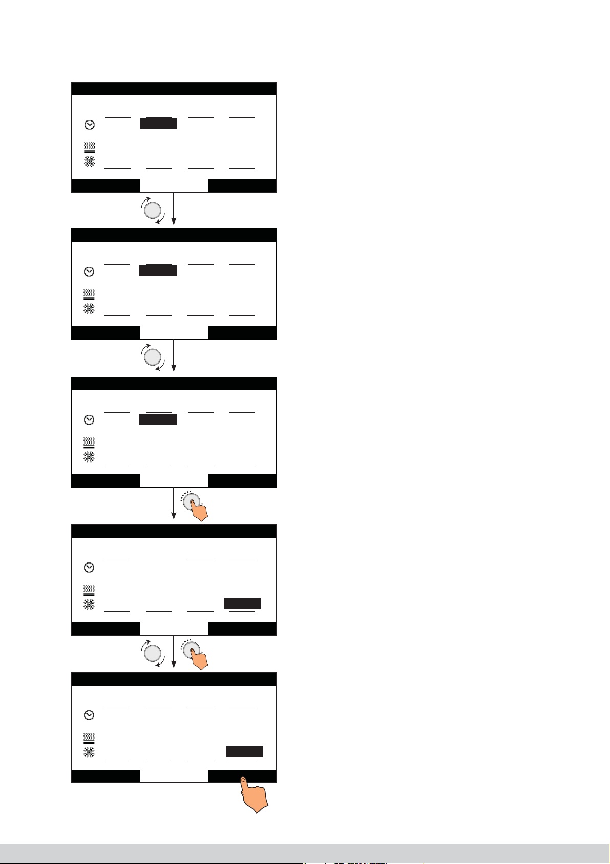
12.5 Switching off periods (max. of 2 periods)
Time scheduling
Saterday-SundayDay/s
07:00
wake
22°C
24°C
09:00
leave
18°C
28°C
17:00
return
18°C
24°C
22:45
sleep
22°C
26°C
Cancel Conrm
Time scheduling
Saterday-SundayDay/s
07:00
wake
22°C
24°C
17:00
leave
--°C
--°C
17:00
return
18°C
24°C
22:45
sleep
22°C
26°C
Cancel Conrm
Time scheduling
Saterday-SundayDay/s
07:00
wake
22°C
24°C
22:45
leave
--°C
--°C
22:45
return
--°C
--°C
22:45
sleep
22°C
26°C
Cancel Conrm
Time scheduling
Saterday-SundayDay/s
07:00
wake
22°C
24°C
22:45
leave
--°C
--°C
22:45
return
--°C
--°C
22:45
sleep
22°C
26°C
Cancel Conrm
Time scheduling
Monday-FridayDay/s
07:00
wake
22°C
24°C
09:00
leave
18°C
28°C
17:00
return
18°C
24°C
22:45
sleep
22°C
26°C
Cancel Conrm
IHL_UDARA_2016_11_04_BEGB
37

13 EC Declaration of conformity
Multicalor Industries NV
Blarenberglaan 21
2800 Malines (Belgique)
declares that the gas-fi red air heaters
• Multicalor Udara 10 (DF)
• Multicalor Udara 15 (DF)
• Multicalor Udara 20 (DF)
• Multicalor Udara 30 (DF)
• Multicalor Udara 40 (DF)
• Multicalor Udara 50 (DF)
are in accordance with the following directives:
• 2009/142/EC : Gas Appliance Directive
• 2006/42/EC : Machinery Directive
• 2004/108/EC : EMC Directive
• 2006/95/EC : Low Voltage Directive
• 2011/65/EU : Hazardous Substances Directive
and has a CE label with numbe E1432/5671 issued by Technigas, Vilvoordsesteenweg 156, 1120 Brussels.
Specifi cally applied harmonised standards:
• EN 1020: Non-household gas-fi red air heaters with forced convection for space heating with a net heat
load of up to 300 kW and a fan for the transport of the combustion air and/or gases
• EN 1196: Domestic and non-domestic gas-fi red air heaters. Supplementary requirements for condensing
air heaters
• EN 1319: Domestic gas-fi red forced convection air heaters for space heating, with fan-assisted burners
not exceeding a net heat input of 70 kW.
Multicalor Industries, moreover, declares that Udara air heaters are produced from high-quality materials and
that the appliances are under the permanent quality control of Technigas.
Malines, 2016-05-08
Steven Tolleneer
Directeur Multicalor Industries NV
38
IHL_UDARA_2016_11_04_BEGB

14 Declaration of conformity KB 2004-01-08
Multicalor Industries NV
Blarenberglaan 21
2800 Malines (Belgique)
Declares that the gas-fi red air heaters
• Multicalor Udara 10 (DF)
• Multicalor Udara 15 (DF)
• Multicalor Udara 20 (DF)
• Multicalor Udara 30 (DF)
• Multicalor Udara 40 (DF)
• Multicalor Udara 50 (DF)
meet the requirements set in Section 4 of the Royal Decree of 8 January 2004 with regard to emissions of
nitrogen oxides and carbon monoxides.
The emissions amount to the following for all types:
Polluant CO [mg/kWh] NOx [mg/kWh]
Mesure < 15 < 30
The EC type investigation as determine in Annex II of the Royal Decree as well as safeguarding the conformity
type as determined in Annex III are performed by:
Technigas, Vilvoordsesteenweg 156, 1120 Brussels (0461).
Used harmonised standard:
• EN 1020: Non-household gas-fi red air heaters with forced convection for space heating with a net heat
load of up to 300 kW and a fan for the transport of the combustion air and/or gases
• EN 1319: Domestic gas-fi red forced convection air heaters for space heating, with fan-assisted burners
not exceeding a net heat input of 70 kW.
Malines, 2016-05-08
Steven Tolleneer
Directeur Multicalor Industries NV
IHL_UDARA_2016_11_04_BEGB
39

For more information you can contact your installer
Read this document before starting the installation or using the
appliance. After commissioning, give instructions to the user and
keep this document in the immediate vicinity of the appliance.
This appliance may not be operated by children, people with
a diminished mental capacity, physical impairments or lack of
knowledge unless under supervision or after receiving training
on how to use the appliance safely and as long as
they are aware of the possible risks. Children may not play with
the appliance under any circumstances. Cleaning and maintenance performed by the user may never be carried out by
children without supervision
Multicalor Industries NV
Blarenberglaan 21 • B–2800 Malines
Tel.: +32 15 29 03 03 • Fax: +32 15 29 03 20
info@multicalor.be • www.multicalor.be
IHL_UDARA_2016_11_04_BEGB
 Loading...