

MC-EE
Manual
MC-EE 20
MC-EE 30
MC-EE 40
Air handlers featuring an advanced electronic modulating controller
and electronically commutates high eciency fan motor
(electronically enhanced)
Heating Cooling Ventilating

Table of contents
1 General 4
2 Technical data 4
2.1 General 4
2.2 Prestaties van de toestellen 4
2.3 Correction factors for other hot water supply- or entering air temperatures 4
3 Operating and setting 5
3.1 General 5
3.2 The control panel 5
3.2.1 Basic screen 5
3.2.2 Locking 5
3.3 Changing settings 5
3.3.2 Low, average and high speed 6
3.3.3 Relationship between the air temperature and air speed, fan curve 6
3.3.4 Setting the language 7
3.3.5 Setting the time and date 7
3.3.6 Screen cleaning 7
3.3.7 Installer’s menu 7
3.3.8 Information screens 7
4 Installation 8
3.1 General 8
3.1.1 Transport damage 8
3.1.2 Packaging 8
3.1.3 Location 8
3.1.4 Minimal clearance 8
3.1.5 Transport on site 8
3.2 Electrical installation 8
3.2.1 Electrical connections 8
3.2.2 Thermostat 8
4.3.3 Advanced options 9
4.4 Installing the hot water supply lines 9
4.4.1 Hydraulic installation, simple version 9
4.4.2 Hydraulic installation, extended version 10
4.5 Installing the ducting system 10
4.5.1 Fitting the supply ducts 10
4.5.2 Fitting the return air ducts 10
4.6 Commissioning 10
4.6.1 Switching the apparatus ON an OFF 10
4.6.2 Setting the air temperature 10
4.6.3 Settingtheairow 10
5 Maintenace 11
5.1 Maintenance by the end user 11
5.1.1 Cleaningtheairlter 11
5.1.2 Cleaning the casing 11
5.1.3 Cleaning the display 11
5.2 Maintenance by the installer 11
6 Electrical wiring 12
7 Warranty 13
7.1 General 13
7.2 Scope and duration of the warranty 13
7.3 Damage that is not covered by the warranty 13
7.4 Not covered under warranty 13
7.5 Repairs 13
7.6 Service-parts 13
8 Statement of compliance 14
2 Document: IV_MCEE_2016_11_22

Dimensions
0
0
,
0
0
5
0
0
,
0
7
4
B
A
0
0
,
0
0
1
1
0
0
,
1
1
0
9
0
,
0
0
8
0
0
,
6
0
0
0
,
4
6
6
3
0
0
,
0
5
5
D
0
0
,
3
7
6
0
0
,
0
2
7
C
Type A B C D
0
0
,
0
0
6
MC-20 340 400 280 220
MC-30 440 500 380 320
MC-40 540 600 480 420
Document: IV_MCEE_2016_11_22 3

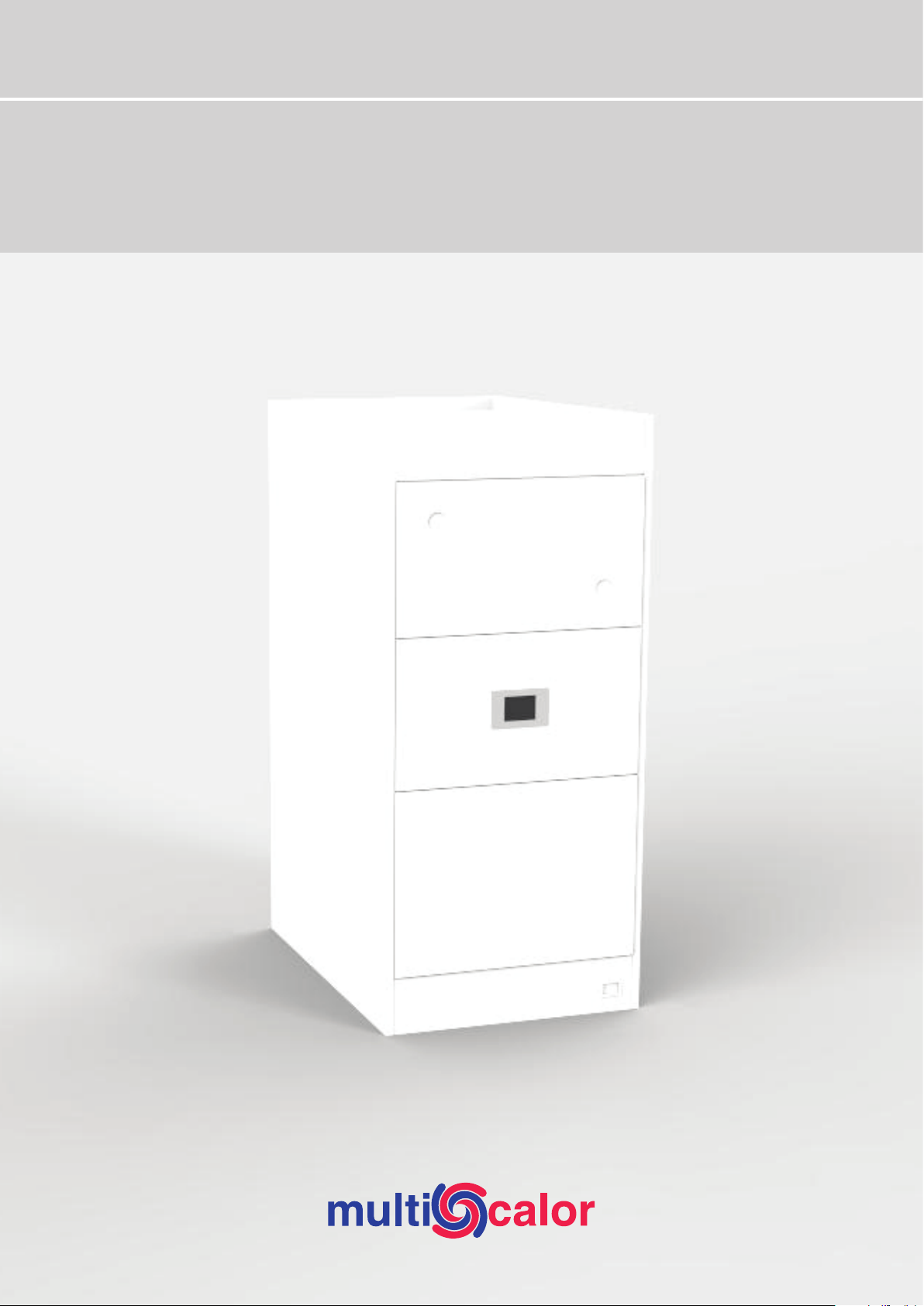
1 General
The Multicalor MC-EE (modulating) air handling units are
compact high performance units. The units are fitted with generously sized heat exchangers featuring 6 rows. This guarantees high air temperatures even with moderate supply water
temperatures. As a result, the units are very well suited to be
used in conjunction with modern condensing boilers.
The fans of the MC units are installed downstream of the heat
exchangers. This ensures that the fan motors are always optimally cooled and the life span of the fan bearings is increased.
Special attention has been paid to the air tightness of the
units, so leak losses are minimal. The heat exchanger compartments is insulated by means of a thick layer of air, so heat
losses are minimal. The apparatus is supplied ready to use. It
is sucient to install on site the hot water supply lines, the air
ducts and the electrical supply.
The MC-EE is fitted with an advanced controller based on an
Atmel RISC microcontroller and a high performance and high
eciency electronically controlled fan motor.
2 Technical data
In standard use the apparatus is used to distribute recycled air
to which not more than 25% outside air has been added, or to
distribute up to 100% outside air after heat reclaim. The unit is
factory supplied in this version.
In outside air version the unit is used to distribute air to which
more than 25% outside air is added. You can activate a special
program in the controller as to maintain a minimum air temperature (for best results an optional modulating 3-way valve
should be connnected). When this option is activated, a basic
frost-protection is activated to help protect the heat exchanger in case of frost danger. Nevertheless we suggest adding a
suitable anti-freeze solution to the heating circuit if the unit is
used as an outside air version.
The Multicalor MC units are available as upflow models. If you
need a downflow unit, you can turn simply around the unit
and flip the controller panel. Pay attention as to not drop the
panel – this may damage the flatcable connector.
2.1 General
The units comply to the machine directive 89/392/EEG, the
low voltage directive 73/23/EEG and the EMC directive
89/336/EEG.
The MC units are available in 3 sizes. Each unit is fitted with
an electronically commutated fan. You can easily change
the maximum airflow by reprogramming the unit via the
touscreen.
2.2 Prestaties van de toestellen
Unit MC-EE 20 MC-EE 30 MC-EE 40
Fan data Type 9/7 10/8 10/10
Motor power Wat t 376 550 736
Air flow (min-max) m³/h 1 500 2 250 3 000
Opgenomen vermogen (80% speed) A 1.40 1.90 2.20
Hydraulic pressure drop kPa 3.51 3.81 4.61
Heating output (75/65-20°C (EN442)) kW 20.0 30.0 40.0
Waterdebiet l/s 0.5 0.74 0.98
Weight kg 68 78 88
2.3 Correction factors for other hot water supply- or entering air temperatures
Hot water supply Air temperature entering the unit
30 25 20 18 15 10
90/70 99% 109% 119% 123% 129% 138%
75/65 81% 90% 100% 104% 110% 119%
70/50 52% 63% 74% 78% 84% 94%
60/50 48% 58% 68% 72% 78% 88%
45/40 23% 34% 44% 48% 54% 64%
4 Modifications reserved Document: IV_MCEE_2016_11_22
3 Operating and setting
3.1 General
The MC-EE is fitted with an advanced controller based on an
Atmel RISC microcontroller and a high performance and high
eciency electronically controlled fan motor.
A control panel has been installed on the appliance to change
the dierent settings of the appliance. The control panel is
equipped with a capacitive touch screen and a TFT colour
screen.
3.2 The control panel
A control panel has been installed on the appliance to change
the dierent settings of the appliance. The control panel is
equipped with a capacitive touch screen and a TFT colour
screen.
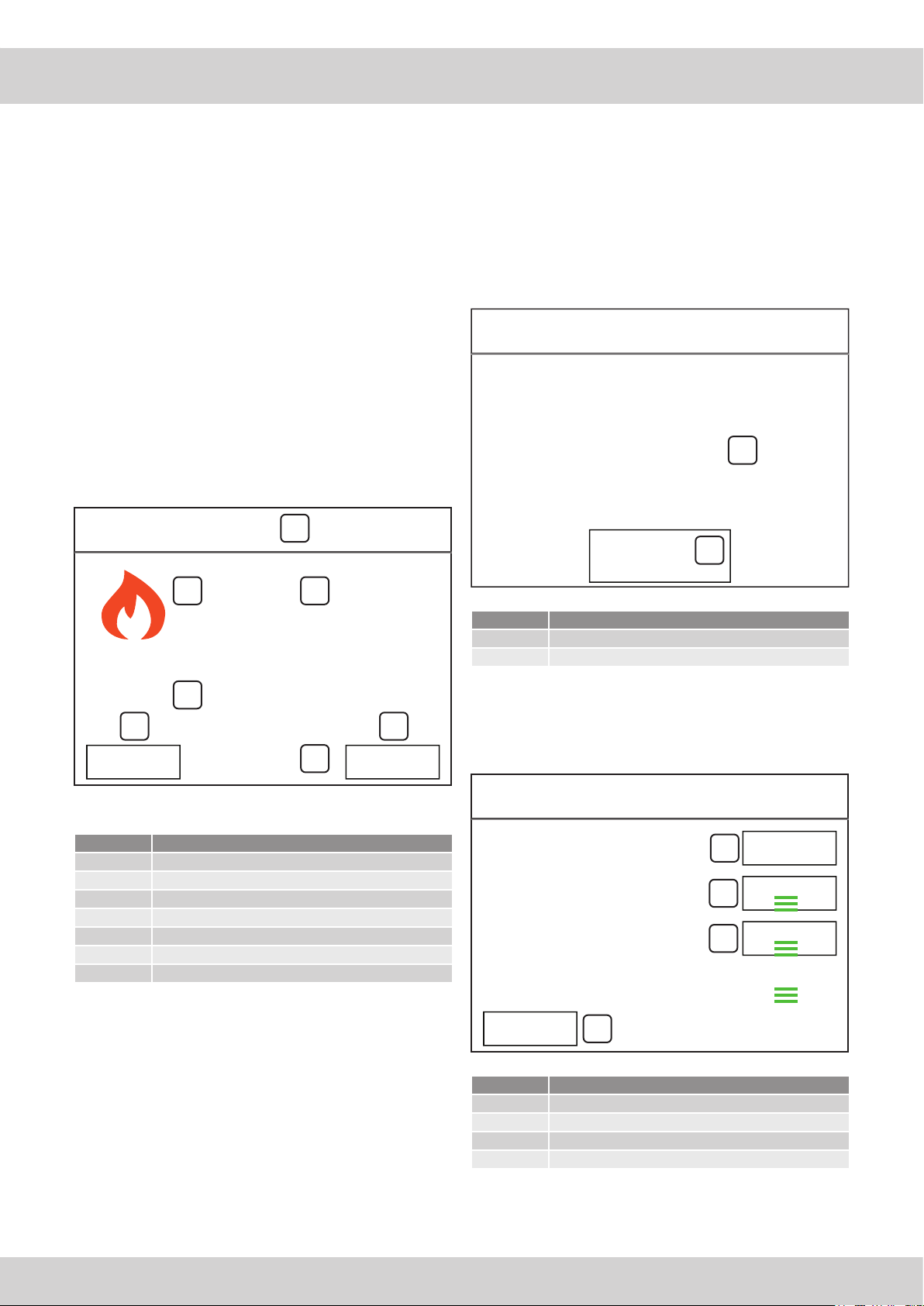
3.2.1 Basic screen
The following information is displayed on the screen as
standard.
Multicalor
7
28-03-2015
3.2.2 Locking
If an error occurs that puts the safe operation of the appliance
at risk, the appliance will be locked. The cause for locking the
appliance is shown on the screen. The locking can be cancelled
by pressing the unlock button. If the error, however, has not
been resolved, the appliance will again be locked.
You must then contact your installer or the manufacturer for a
solution.
Error
Fout
7
1
E40: NTC 1 ERROR
6
2
1 2
3
21:33
3
Legend
Number Meaning
1 Function mode of the appliance
2
3 Time
4 Fan speed
5 Information menu button
6 Settings menu button
7 Date
Air temperature
45%
4
53°
56
=
Legend
Number Meaning
1 Error message
2 Unload button
3.3 Changing settings
By pressing the setting button 3 the first screen of the setting
menu will be displayed.
Settings
Instellingen
System
Air heater
Screen cleaning
1
4
1
2
3
Legend
Number Meaning
1 System settings
2 Settings in relation to the air heater operation
3 Screen cleaning
4 Back to the previous menu
Document: IV_MCEE_2016_11_22 Modifications reserved 5

A number of settings are discussed. Since all screens are
accessible through the same process, not all screens will be
discussed.
Airow(CH)
3.3.1 Low, average and high temperature
You can set 3 air temperatures on the MC-EE: a low, average or
high value. To set these values, press the air heater (2) menu
button, next, system fan and then the first fan curve option on
the setting menu.
Fan curve (CH)
Low speed at:
Medium speed at:
High speed at:
4
1
Next, select the value that you want to change. The selected
value (1) will be displayed using an orange colour. By pressing
the key R (5) or S (6) ), you can change the set value.
If you press 1 (4), les modifications sont sauvegardées automatiquement et vous quittez l’écran du menu.
5
9
1
2
3
30°
40°
50°
6
:
Low:
Laag:
Medium:
Midden:
High:
Hoog:
4
1
Next, select the value that you want to change. The selected
value (for example, 3) will be displayed using an orange colour.
By pressing the keys R (6) or S (5), you can change the set
value.
If you press 1 (4), the changes are automatically saved and
you will exit the menu screen.
3.3.3 Relationship between the air temperature and
air speed, fan curve
60°
55°
1
50°
45°
5
9
1
2
3
10%
50%
80%
6
:
3.3.2 Low, average and high speed
On the MC-EE, 3 air speeds can be set for heating: a low, average or high value. To set these values, press the air heater (2)
menu button, next, system fan and, as last, the air flow rate.
40°
2
35°
30°
3
25°
The relationship between the air temperature and air speed
is displayed in the above graph. If the air temperature is lower
than the “low value” (3) parameter, the fan is operational at
the “low” (4) speed. If the air temperature is higher than the
“high value” (1) parameter, the fan is operational at the “high”
(6) speed. In-between these values, the speed of the fan is
automatically adjusted based on the air temperature.
The “average value” (5) and “average” (2) parameters serve as
an additional checking point to ensure you have more control
over the air flow rate.
4 5 6
10% 20% 30% 40% 50% 60% 70% 80% 90%0%
6 Modifications reserved Document: IV_MCEE_2016_11_22

3.3.4 Setting the language
The control can be set to dierent languages. To access this
setting, press the “system” (1) button in the setting menu and,
next, the third option: Language.
Language
Taal
English
Nederlands
4
1
Next, you can set the required language with the R (6) or S
(5).
3.3.5 Setting the time and date
The time and date can be set similarly (not applicable when
using the RC21 thermostat).
3.3.6 Screen cleaning
The touch screen can be temporarily switched o for cleaning
by pressing the clean screen button. Clean the screen using a
microfibre cloth or with a paper tissue.
3.3.7 Installer’s menu
Specific parameters can be found on an installer’s menu to
stop thoughtless changes. This installer’s menu can only be
accessed if a password (a code) is entered.
Installer code
Code User lever
123456 Power user
007007 Installer
5
9
6
:
The code for the “engineer” user level is only released after following training at Multicalor.
Changes do not normally have to be implemented in this
menu.
3.3.8 Information screens
A number of parameters can be read by pressing the information button on the main menu. The information in these screen
can only be read. The parameters cannot be changed. Provisionally, these screens only contain the version number of the
operating software.
Document: IV_MCEE_2016_11_22 Modifications reserved 7

4 Installation
3.1 General
• We wish to emphasize that only qualified fitters or contractors shall install the air heater.
• The installation shall be done in accordance with the
latest issue of all local standards as well as the installation
manual of the device concerned.
• Ensure that the conditions of local utility provision (electrical supply) match the device settings before installing the
device or making it operational.
3.1.1 Transport damage
Please check the air heater for transport damage upon delivery.
If damage is observed, this shall be mentioned on the waybill
and you shall advise your supplier thereof in writing.
3.1.2 Packaging
The air heaters are always packaged in a box made from
recycled paper. We ask you not to earmark the paper for waste
disposal, but for further recycling.
3.1.3 Location
• Adhere to the following guidelines when selecting a location for the device:
• place the unit in a central position in relation to the ducting
system;
• place the unit on a flat and solid surface;
• if installation surface is wet, then raise the unit;
• Always place the device in such a way that it is insulated
from the construction–building structure to avoid the
transmission of noise and vibrations.
Attention:
I The unit must be installed level!
I The device must be installed in a frost free location. If
impossible, please add a suitable anti-freeze to the hydraulic system as to protect the heat exchanger from frost
damage.
I If a return air is inspired in the combustion compartment,
then under no condition devices with an open combustion
circuit may be present in the installation area!
3.2 Electrical installation
The electrical installation shall always be performed according
to the latest issue of the relevant standards and the prescriptions of the local energy provider (utility).
I Mind your safety: always ground the unit.
3.2.1 Electrical connections
In the casing dierent cut-outs are provided to run cables
through. The PCB features a the mains power 230V~AC (marked L, N and GND). Connect with a cable to a 230V~AC power
supply. A seperate earthing plug is provided next to the PCB.
We recommend that the machine should be directly connected
to a switchboard with 16A fuses.
3.2.2 Thermostat
The device works perfectly together with the Honeywell
electronic programmable thermostat Vision thermostat. This
thermostat is suited for heating, ventilation and cooling, and
has been specifically designed for use with warm air systems.
Connect the thermostat as per the instructions on the wiring
diagram.
Attention: mind the connections. (See chapter electrical
wiring)
Mount the room thermostat at an approximate height of 1.6 m,
in a central position in the living room and readily accessible to
the normal air circulation in the room.
Always mount the thermostat on an inner wall shielded from
the eects of other heat sources including exhaust grilles, powered devices, direct sunlight, etc. Accordingly, we also do not
recommend placement near windows, outer walls (<1.20 m) or
in the vicinity of stairs. For additional information on assembly
and programming we refer to the thermostat manual.
3.1.4 Minimal clearance
When installing please provide minimal clearance around the
unit:
• keep 50 mm clearance around the sides of the unit;
• keep a minimum of 50 mm between hot water supply and
any flammables..
• At the front of the device there shall be at least 720 mm of
free service space (ensure a comfortable standing height).
3.1.5 Transport on site
Never move the air heaters by tilting them on their angles,
as this may irrevocably damage the device encasing. Such
damage is not covered by the device’s warranty.
8 Modifications reserved Document: IV_MCEE_2016_11_22

4.3.3 Advanced options
4.3.3.1 External condensing unit relay
The PCB features a relay that can make or break an external
condensing unit supply or control line. For further information,
please contact Multicalor and the condensing unit manufacturer. The coolrequest terminal is RE 1.
4.3.3.5 Extension board
It’s possible to connext an extension PCB board to achieve
multiple zone control.
For more information contact the manufacturer.
4.3.3.2 Burner relay
This contact is used to create a heat request on the boiler. or it
can be used to power a solenoid or a circulator. It could also be
used to power an oil burner on an oil fired boiler. The RE 3
connector will close when the MC unit needs heat, open when
the air temperature is higher than the calculated set–point.
4.3.3.3 Heat pump relay
The PCB features a relay RE2 that can be used to control a
heat pump.
Contact us for more information.
4.3.3.4 3-way Valve
It’s possible to control a 3-way valve via the 0-10V control
voltage.
Contact us for more information.
4.4 Installing the hot water supply lines
The diameter of the supply lines is 28mm. Usually hot water
supply is from the front, but for ease of installation the supply
lines can also be brought in from the sides or the top of the unit
(UP F only). The heat exchanger is installed with rubber grommets as to minimise leakage.
L Install an automatic air bleed valve in the supply circuit.
L Install ball valves and flexible tubing so the heat exchan-
ger can be easily removed for inspection or cleaning.
4.4.1 Hydraulic installation, simple version
You can choose to install the MC in a simple way. However, this
will result in a loss of certain options.
If you choose this way of installing, it is adviseable to have the
water temperature of the boiler limited by means of a weather
dependent controller.
22
2 3
2
1
Onderdeel Functie
1 Air heater MC-EE
2 Boiler
3 Thermostat
4 Optional outside sensor
5 One-way valve
4
5
Document: IV_MCEE_2016_11_22 Modifications reserved 9

4.4.2 Hydraulic installation, extended version
• We suggest using valves with following KVS factors:
MC20: KVS10
MC30: KVS10
MC40: KVS16
• We suggest that you do not give priority to the hot water
system but install the system in such a way that both
heating and hot water demand can run together.
• Best results are obtained if the boiler temperature is controlled via a weather compensator.
3
22
7
M
6
5
1
2
2
4
4.5.2 Fitting the return air ducts
Noise problems are often created if air heaters are used with
very short and/or undersized return air ducts. These problems
can be avoided by:
• insulating the return air ducts by means of an acoustic
liner;
• installing a sound damper in the return air ducts;
• making sure the that there are at least 2 generously sized
90° turns in the ducting system;
• Increasing both diameter and length of the return air
ducts.
You can connect the return air duct to the left, right or the
bottom of the unit. We strongly suggest using only the bottom
return air opening (please remove the cut-out when commis-
sioning). If possible, install the unit on an insulated plenum, on
which side return ducts can be connected. If you do not have
sucient free space to use an insulated return air plenum, it
is possible to install an optional side filter frame. However, in
doing so, a large part of the acoustic insulation is lost. Always
use a return air duct and return air from OUTSIDE of the combustion compartment. If you do wish to apply an open return,
make sure that there are (will be) no other devices with open
combustion circuit in the installation area.
Number Function
1 Heat exchanger MC-EE
2 Boiler
3 Thermostat connected to MC-EE
4 Optional outside sensor
5 One-way valve
6 Circulator (Field wiring)
7 3-way valve; 0-10V control voltage (O1)
Attention
I The 3-way valve must be powered externaly
4.5 Installing the ducting system
4.5.1 Fitting the supply ducts
Fit a matching supply air on the unit. The height of the plenum
should be at least as high as the width of the unit. The supply
air plenum should, like the supply ducting system, be thermally
insulated. The supply air duct should be of a sucient size
to permit air displacement with normal speeds and pressure
losses.
4.6 Commissioning
4.6.1 Switching the apparatus ON an OFF
Normally the machine shall permanently be supplied with
mains power. At the installation or maintenance stage you
may proceed as follows to switch on or o the device.
Proceed as follows to switch the machine ON:
• Connect the mains power.
• Set the room thermostat at the desired setting.
Proceed as follows to switch the machine OFF:
• Set the room thermostat 5°C lower than the actual temperature.
• Disconnect mains power.
4.6.2 Setting the air temperature
You will need to set the minimum and maximum air temperature of the unit. This can be done by the display. For more
information please refer to chapter 3.
4.6.3 Setting the air flow
You will need to set the minimum and maximum air flow of
the unit. This can be done by the electronic display. For more
information please refer to chapter 3.
10 Modifications reserved Document: IV_MCEE_2016_11_22

5 Maintenace
5.1 Maintenance by the end user
5.1.1 Cleaning the air filter
The standard air filter is a synthetic air filter with a life span
of 1 year. However the filter requires monthly cleaning, to be
performed as set out below:
• Set the thermostat 5°C lower than the environment
temperature.
• You may wait until the apparatus has cooled down.
• Disconnect the mains.
• Remove the air filter and use a vacuum cleaner to clean it
• Put the filter back into the machine.
• Restore the mains.
• Set the room thermostat again to the required value.
Never remove the air filter from an MC unit. The machine must
always be fitted with a EU3 (or better) air filter. Heating or ventilating without a filter may pollute the heat exchanger to such
an extent that the machine may incur irretrievable damage,
which the warranty does not cover.
5.1.2 Cleaning the casing
The casing may be cleaned with a soft humid cloth. Do not use
aggressive media such as bleaching water, solvents or petrol,
as these products are likely to damage the paint.
5.2 Maintenance by the installer
The unit is nearly free of maintenance. It is sucient to replace
the air filter and to check the unit for leakage and proper
functioning.
• Set the thermostat 5°C lower than the environment
temperature;
• You may wait until the apparatus has cooled down;
• Disconnect the mains;
• Remove and replace the air filter;
• Check unit for functioning and check for leaks;
• Verify pressure in the supply lines;
• Switch mains power on;
• Set the room thermostat again to the required value;
5.1.3 Cleaning the display
The touch screen can be temporarily switched o for cleaning
by pressing the clean screen button. Clean the screen using a
microfibre cloth or with a paper tissue.
Document: IV_MCEE_2016_11_22 Modifications reserved 11

6 Electrical wiring
THERMOSTAT
W G R
Heat (I1)
Venlaon (I3)
Y
Cool (I2)
Ground (GND)
Print 0D1
Print 0DA_MC
FAN J7
0-10V DC
O1
GND
GND
GND
Common
I1
Heat
I2
Cool
I3
Ven t
A
NTC1
NTC2
NTC2
NTC1
DISP J6
B
GND
V12
Flat Cable
POT
SW1
RE1 RE2 RE3
NO
COMNOCOM
NO
COM
Green/Yellow
L/N/PE
2016-11-22
FAN
C/Rx/Tx/V
PE
PE
L
N
L
Brown
N
Blue
230VAC/16A
B-2800 Mechelen
Blarenberglaan 21
Mulcalor Industries NV-SA
MC-EE UF/DF
NC
Return Air
Supply Air
AIRCO
BURNER
HEATPUMP ON
SW1
ON
1 2 3 4
ALL 4 OFF
12 Modifications reserved Document: IV_MCEE_2016_11_22

7 Warranty
7.1 General
Multicalor Industries NV guarantees the MC units against
all manufacturing defects or material faults, subject to the
terms and conditions described under ‘Scope and duration of
the warranty’. Moreover Multicalor Industries NV guarantees
the machine will achieve the output indicated in normal
conditions.
7.2 Scope and duration of the warranty
The warranty starts at the moment of purchase by the first
user and entitles the beneficiary of the warranty, through the
dealer or the service department of Multicalor Industries NV, to:
• One (1) year free exchange of faulty parts;
• Five (5) year free exchange of the heat exchanger, but
exclusive of labour costs and travel expenses.
Replacement of parts does not change the initial warranty
period, i.e. the warranty is not extended by the replacement of
faulty parts.
7.3 Damage that is not covered by the
warranty
All damage resulting from:
7.4 Not covered under warranty
• Parts subject to normal wear, including air filters, fuel filters
and other parts that have to be replaced periodically;
• Machines the serial number of which has been removed or
altered;
• Travel expenses and labour costs if the matching warranty
period has expired;
• Result damage caused by the faulty machine;
• Any loss of productivity attributable to the faulty machine;
• Any loss of use caused by a fault to the machine;
• When the machine proves unsuitable for the purposes for
which the purchaser bought the machine.
7.5 Repairs
During the warranty period the customer may call upon the
services of the dealer who sold the machine or, in Belgium, to
the “after-sales” department of Multicalor Industries NV.
7.6 Service-parts
If it is necessary to replace a part, we recommend that the
matching article code of the part concerned be mentioned on
the order, in addition to the type of air heater, the machine’s
serial number as well as the name of the part concerned. The
machine type and serial number are mentioned on the registration plate placed in the machine.
• Machine use which does not match normal household or
light commercial use;
• Failure to meet the user instructions as summed up in the
user manual;
• Insucient or wrong maintenance;
• Irretrievable fouling up of the heat exchanger caused by
heating, ventilating or cooling with a highly fouled up or
absent dust filter;
• Modifications or adaptations to the machine not covered
by prior written approval by Multicalor Industries NV;
• Repairs carried out with non-original parts or wrong equipment or materials;
• The heat exchanger when used in an atmosphere polluted
with chlorine or other chemicals;
• Causes foreign to the machine, including (but not restricted to):
1. Damage incurred during transport, including
dents, scratches, etc.;
2. Damage caused by disasters, including fire,
lightning, flooding;
3. Damage linked to frost;
4. Damage caused by a departure from the
normal power voltage, water or gas pres
sure deviating widely from the nominal
values suitable for the normal supply of the
machine;
5. Damage caused by a non-conformity of the
installation to the local standards
applicable.
Document: IV_MCEE_2016_11_22 Modifications reserved 13

8 Statement of compliance
Multicalor Industries declares that the air handlers
• Multicalor MC 20
• Multicalor MC 30
• Multicalor MC 40
meet the provisions of the machine directive 89/392/EEC, the low-voltage directive 73/23/EEC as well as the EMC directive
89/336/EEC.
14 Modifications reserved Document: IV_MCEE_2016_11_22

Document: IV_MCEE_2016_11_22 Modifications reserved 15

For more information contact your installer
Last modification
22 november 2016
Multicalor Industries NV • Blarenberglaan 21 • B-2800 Mechelen (Belgium)
www.multicalor.be • Tel.: +32 15 29 03 03 • Fax: +32 15 29 03 20 • info@multicalor.be
 Loading...