

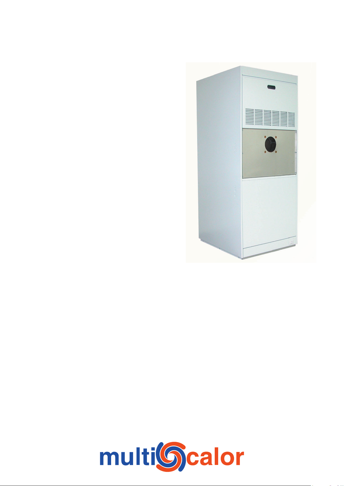
Multicalor O
Oil fired warm air heaters
Brand: Multicalor
Base model: O24 UF
Variants: O24DF
O28UF – O28 DF
O33UF – O33 DF
O41/48 UF - O41/48 DF
Country of destination: UNITED KINGDOM
Electrical supply: 230V AC – 50Hz
Manufacturer: Multicalor Industries NV
Blarenberglaan 21
B–2800 MECHELEN
Tel.: +32 (0)15 29 03 03
Fax: +32 (0)15 29 03 20
Date created: 1/09/2004
Datum latest change: 1/09/2004
Please keep this manual close to the apparatus for further reference
Document code: O24_uk_en.pdf

3
Table of contents
Dimensional data UPFLOW 3
Dimensional data DOWNFLOW 4
1 General 5
1.1 Normal version 5
1.2 Make–up air version 5
1.3 Upflow and Downflow models 5
2 Technical data 5
2.1 General 5
2.2 Air Flow 5
3 Installation 5
3.1 General 5
3.2 Electrical installation 6
3.3 Installing oil supply lines 7
3.4 Installing the ducting system 7
3.5 Installing the flue gas exhaust 7
4 Commissioning 7
4.1 Switching the apparatus on and off 7
4.2 Setting the air temperature 7
4.3 Setting the air quantity 7
4.4 Outside air version 8
4.5 Downflow versions 8
4.6 Installing the ducting system 8
4.7 Commissioning the burner 8
4.8 Fan and limit controller 8
5 Maintenance 9
5.1 Maintenance by the user 9
5.2 Maintenance by the installer 9
6 Problem solving 9
6.1 Unit won’t start during heat request 9
6.2 Fan keeps on running 10
7 Electrical wiring diagrams 10
7.1 Upflow units 10
7.2 Downflow units 11
8 Warranty 11
8.1 General 11
8.2 Scope and duration of the warranty 11
8.3 Damage that is not covered by the warranty 11
8.4 Not covered under warranty 12
8.5 Repairs 12
8.6 Service sets 12
9 Statement of compliance 13
2
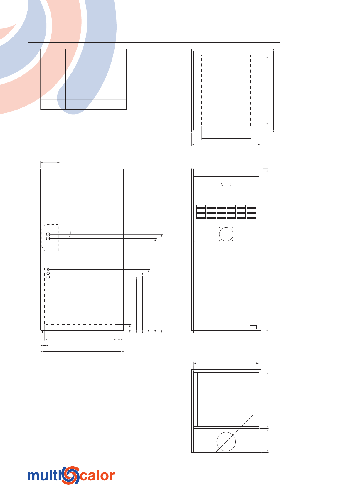
Dimensional data UPFLOW
1 300
780
747
502
472
442
60
65
A
575 x 450
55
1
50
520
B
192
390
550
A
560
C
Type
O18
O24
O28
O33
O41-48
A
660
660
660
660
760
B C
452
452
452
452
552
205
205
–
–
–
3

5
Dimensional data DOWNFLOW
1 300
15
0
520
552
192
60
760
820
850
880
400
550
760
A
Type
O18 DF
O24 DF
O28 DF
O33 DF
O41-48 DF
A
520
520
520
560
660
4
1 General
The Multicalor oil fired warm air heaters have been specifically designed for domestic and light commercial use. They feature
a high quality ferritic stainless steel heat exchanger and efficient direct driven fan.
The heaters are delivered without burner. A high quality burner (preferably with pre-heating) should be installed by the
installer during fitting. Every single fan has been tested for proper functioning before leaving our premises. The label inside
the unit states the proper nozzle and burner working pressure. After the ductwork, burner, electrical connections and flue pipes
have been connected, the unit is ready to be used.
The warm air heaters must only be commissioned by approved installers. Every installation should comply with local rules.
1.1 Normal version
In standard use the apparatus is used to distribute recycled air to which not more than 25% outside air has been added, or to
distribute up to 100% outside air after heat reclaim. The unit is factory supplied in this version.
1.2 Make–up air version
In make-up air version the unit is used to distribute air to which more than 25% outside air is added. However, in the unit no
special regulators are installed to keep the air temperature constant. If you want to use the unit as an outside air unit, we suggest
that you add thermal insulation to the front fan access panel to prevent condensation.
1.3 Upflow and Downflow models
The Multicalor oil units are available in upflow and downflow version. Please state the desired version when ordering. The
units can NOT be converted on site.
2 Technical data
2.1 General
The heaters comply to CE regulations regarding the machine directive 89/393/EEG, the low voltage directive 72/23/EEG and
the EMC directive 89/336/EEG. The units are available in different capacities.
2.2 Air Flow
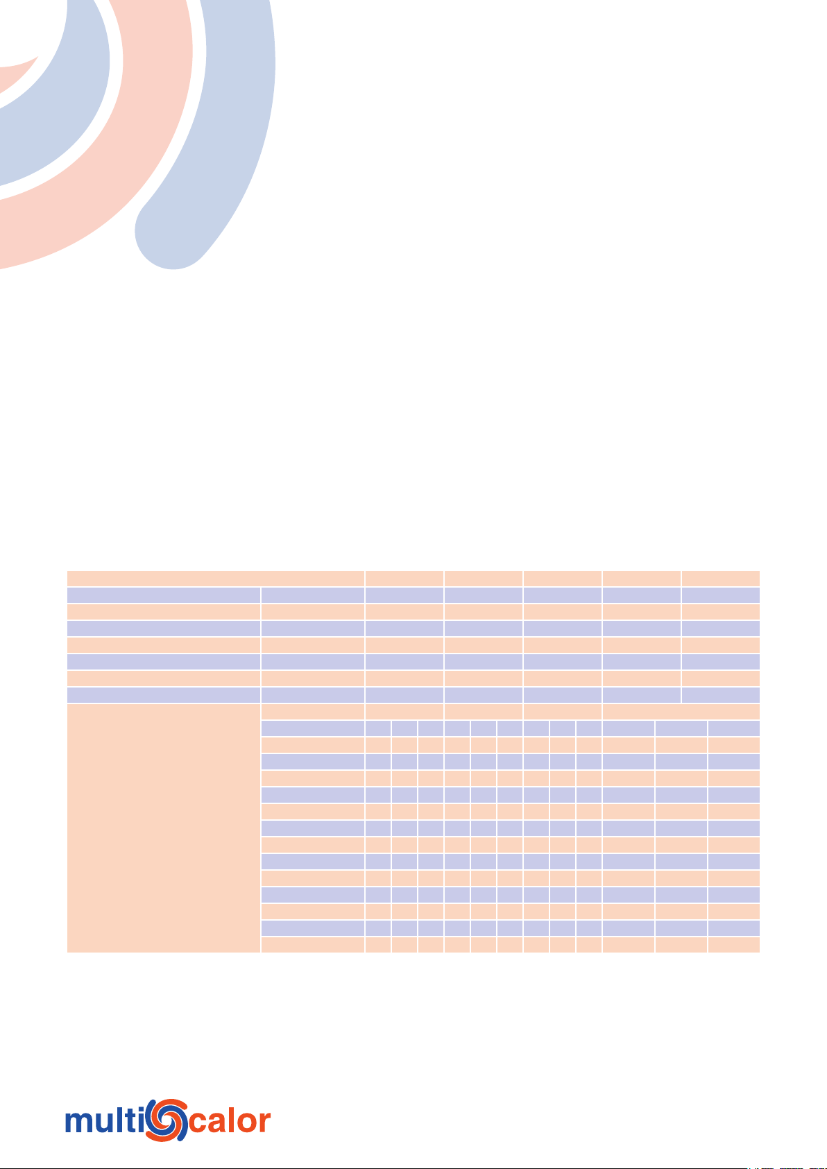
Type O24 [DF] O28 [DF] O33 [DF] O41 [DF] O48 [DF]
Nett output kW 24.0 28.0 33.0 41.0 48.0
Gross input kW 26.3 30.7 35.8 44.5 53.3
Nozzle GPH 0.55–60°–S 0.65–60°–S 0.75–60°–S 1.10–60°–S 1.10–60°–S
Burner pressure kg 11.0 11.0 11.0 10.0 11.0
Electrical absorbed power A 3.0 5.0 5.0 7.0 7.0
Electrical supply V-F-Hz 230–1–50 230–1–50 230–1–50 230–1–50 230–1–50
Oil consumption kg/h 2.24 2.61 3.08 3.83 4.53
Air flow Speed Speed Speed Speed
m³/h L M H L M H L M H L M H
1 200 138 162 173
1 400 107 143 154 94 253 340 166 297 374
1 600 58 119 136 9 200 303 77 255 345
1 800 90 114 125 260 208 312
2 000 51 87 212 146 273 200 288 359
2 200 56 150 63 230 107 242 330
2 400 23 78 182 181 295
2 600 120 108 255
2 800 54 16 210
External static pressure in N/m²
3 000 157
3 200 100
3 400 29
3 600
3 Installation
3.1 General
• We wish to emphasize that only qualified fitters or contractors shall install the air heater.
• The installation shall be done in accordance with the latest issue of all local standards as well as the installation manual
of the device concerned.
• Ensure that the conditions of local utility provision (electrical and oil supply) match the device settings before installing
the device or making it operational.
5

7
3.1.1 Transport damage
Please check the air heater for transport damage upon delivery. If damage is observed, this shall be mentioned on the waybill
and you shall advise your supplier thereof in writing.
3.1.2 Packaging
The air heaters are always packaged in a box made from recycled paper. We ask you not to earmark the paper for waste
disposal, but for further recycling.
3.1.3 Combustion compartment
Adhere to the following guidelines when selecting a location for the device:
• place the unit in a central position in relation to the ducting system;
• place the unit in a central position in relation to the flue gas exhaust / chimney;
• place the unit on a flat and solid surface;
• if installation surface is wet, then raise the unit;
• a suitable air supply should be provided for combustion purposes;
• return air must be connected to unit from outside the combustion compartment;
• Always place the device in such a way that it is insulated from the construction–building structure to avoid the
transmission of noise and vibrations.
Attention:
• The unit must be installed level!
• If possible, install the device in a frost free location.
3.1.4 Clearances
When installing please provide minimal clearance around the unit:
• Position the unit with a minimum clearance of 50 mm to walls;
• In front of the unit, a minimum space of 760mm should be reserved for servicing purposes;
• A clearance of 150 mm is advised around the flue pipe;
• Please do not install this heater if walls, floors or ceiling are constructed of easily flammable material.
3.1.5 On–site transport
Never move the air heaters by tilting them on their angles, as this may irrevocably damage the device encasing. Such damage
is not covered by the device’s warranty.
3.2 Electrical installation
The electrical installation shall always be performed according to the latest issue of the relevant standards and the prescriptions
of the local energy provider (utility).
• Mind your safety: always ground the unit!
3.2.1 Electrical connections
In the casing different cut-outs are provided to run cables through. The PCB features a three-pole terminal for connecting
the mains power 230V~AC. Connect the cable to a 230V~AC power supply with earthing. We recommend that the machine
should be directly connected to a switchboard with 16A fuses.
3.2.2 Thermostat
The device works perfectly together with the Honeywell electronic programmable thermostat Chronotherm IV. This thermostat
is suited for heating, ventilation and cooling, and has been specifically designed for use with warm air systems. Connect the
thermostat as per the instructions on the wiring diagram.
Mount the room thermostat at an approximate height of 1.6 m, in a central position in the living room and readily accessible
to the normal air circulation in the room. Always mount the thermostat on an inner wall shielded from the effects of other heat
sources including exhaust grilles, powered devices, direct sunlight, etc. Accordingly, we also do not recommend placement
near windows, outer walls (<1.20 m) or in the vicinity of stairs. For additional information on assembly and programming we
refer to the thermostats’ manual.
3.2.3 Condensing unit
The PCB features a two-pole terminal for connecting an auxiliary relay that can start an external condensing unit. Warning:
never connect the cooling system relay directly to this output, but always use an auxiliary relay. For further information, please
contact Multicalor.
6

3.3 Installing oil supply lines
Oil connections should be fitted only by an approved installer. Please consult your burner manual in order to find the
instructions on how to connect the oil lines. We strongly suggest placing an oil filter in the oil supply lines.
3.4 Installing the ducting system
3.4.1 Installing supply ducts
For the O units a complete range of acoustically insulated supply air plenums is available, manufactured in white painted steel.
These are installed of top of the unit (Downflow versions: under the unit) and facilitate connection of the ductwork.
3.4.2 Installing return ducts
For the O units a complete range of acoustically insulated return air plenums is available, manufactured in white painted steel.
These are installed under the unit (Downflow versions: on top of the unit) and facilitate connection of the ductwork. It is also
possible to connect the return air ductwork to the side of the units. For this purpose matching white return air filter frames
are available. Multicalor does not recommend to connect the ductwork directly to the sides of the unit, as this means that a
large portion of the acoustic insulation is lost. If you wish to use an open return, you can order a perforated return air plenum.
ATTENTION: open return systems are only allowed if the unit is located in the room to be heated (“industrial style” space
heating). Open return systems are not allowed if the air is supplied outside of the room where the unit is installed.
• Never remove the air filter. The unit must always be fitted with an air filter class EU3/G3 or better. Using the unit
without a filter can damage the unit.
• Change filters regularly.
• If you connect an outside air duct, always install a butterfly register as to regulate the amount of outside air.
3.5 Installing the flue gas exhaust
The flue pipe connections should be made according to the local codes. If the flue pipe traverses the roof, the flue pipe and
roof passage should be twin wall as to prevent any condensation occurring because of the sudden cooling of exhaust products.
Because of the very high efficiency of the unit, we strongly suggest using twin wall stainless steel flue pipe for the complete
flue exhaust system:
• respect the advised clearances around the exhaust pipes. (Risk of fire).
• try not to use a multitude of 90° turns.
• when using a horizontal exhaust (not recommended) use a minimum slope of 50 mm/m!
4 Commissioning
4.1 Switching the apparatus on and off
Normally the machine should permanently be supplied with mains power. At the installation or maintenance stage you may
proceed as follows to switch on or off the device.
4.1.1 Switching ON
Proceed as follows to switch the machine ON:
• Connect the mains power.
• Set the room thermostat at the desired setting.
4.1.2 Switching OFF
Proceed as follows to switch the machine OFF:
• Set the room thermostat 5°C lower than the actual temperature.
• Wait for the unit to cool down. This may take a couple of minutes.
• Disconnect mains power.
4.2 Setting the air temperature
4.2.1 Fan and limit controller(s)
Fan and limit controller(s) are set in factory and should not need adjusting under normal circumstances.
4.3 Setting the air quantity
Air volume should be adjusted according to the calculations made by the installer. Please check that the air temperature does
not exceed 65°C after the unit has been turned on for at least 15 minutes.
The fan speed can be selected by switching the connection wires on the PCB, located in the fan compartment. When selecting
the low speed setting, you will usually need to install a smaller nozzle to prevent tripping the overheat thermostat.
• Low speed: red wire
• Medium speed: blue wire
• High speed: black wire
7

9
4.4 Outside air version
In outside air version the unit is used to distribute air to which more than 25% outside air is added. However, in the unit no
special regulators are installed to keep the air temperature constant. If you want to use the unit as an outside air unit, we suggest
that you:
• If you want to use the unit as an outside air unit, we suggest that you add thermal insulation to the front fan access panel
to prevent condensation. Multicalor has a range of suitable acoustic and thermal insulating materials in stock.
4.5 Downflow versions
The Multicalor O–series units are supplied in an UPFLOW version. Downflow versions are available on request.
4.6 Installing the ducting system
4.6.1 Installing the return air ducts
Noise problems are often created if air heaters are used with very short and/or undersized return air ducts. These problems can
be avoided by:
• insulating the return air ducts by means of an acoustic liner;
• installing a sound damper in the return air ducts;
• making sure the that there are at least 2 generously sized 90° turns in the ducting system;
• Increasing both diameter and length of the return air ducts.
You can connect the return air duct to the left, right or the bottom of the unit. We strongly suggest using only the bottom return
air opening (please remove the cut-out when commissioning). If possible, install the unit on an insulated plenum, on which
side return ducts can be connected. If you do not have sufficient free space to use an insulated return air plenum, it is possible
to install an optional side filter frame. However, in doing so, a large part of the acoustic insulation is lost. Always use a return
air duct and return air from OUTSIDE of the combustion compartment. If you do wish to apply an open return, make sure that
the unit is used as a space heater (the unit is ONLY heating the room where it is installed).
ATTENTION:
• Do not forget to remove the cut-out under the unit when using a bottom return (or a side return with bottom plenum).
4.6.2 Supply air ductwork
Fit a matching supply air on the unit. The height of the plenum should be at least as high as the width of the unit. The supply
air plenum should, like the supply ducting system, be thermally insulated. The supply air duct should be of a sufficient size to
permit air displacement with normal speeds and pressure losses.
4.7 Commissioning the burner
Please refer to the installation instructions from the burner manufacturer. First set the desired air speed, then select a nozzle
that has an air temperature of about 65°C (Delta t of 40 to 45°C) after 15 minutes of continuous use. Make sure that the fan
compartment is CLOSED when doing this test.
4.8 Fan and limit controller
The Honeywell fan and limit control is used to switch the fan on and off. The FLC also shuts down the burner if the air
temperature is too high (e.g. when the fan fails to start). This is a safety feature.
4.8.1 Switching the fan on and off
ON: When the air temperature in the heat exchanger compartment
is higher than the set value (e.g. 50°C), the fan is switched ON.
OFF: When the air temperature in the heat exchanger compartment
is lower than the set value (e.g. 30°C) the fan is switched OFF.
This means that the burner is NOT controlled by the fan and limit controller,
but only by the thermostat.
4.8.2 Interrupting the combustion process when the air
temperature in the heat exchanger compartment is too high
STB: When the air temperature in the heat exchanger compartment is higher
than the set maximum temperature (e.g. 90°C) the electrical supply to the
burner is cut. THIS IS A SAFETY FEATURE! The safety needs manual rearming by pushing the red button.
The STB safety only trips when one of the following conditions is true:
1 Air flow too low: increase air flow
8

2 dirty air filters: clean or replace filters
3 too many registers closed: open at least 66% of all registers
4 return air opening closed: open return air system
5 Fan will not function: check fan
If this safety feature trips, the electrical supply to the burner is cut, thereby stopping the combustion process. To re enable the
unit, press the red button. If you have to press the red button often, please consult with your installer. ATTENTION: in the
DOWNFLOW models 2 of these fan and limit controllers are installed.
5 Maintenance
5.1 Maintenance by the user
5.1.1 Cleaning the air filter
The standard air filter is a synthetic air filter with a life span of 1 year. However the filter requires monthly cleaning, to be
performed as set out below:
• Set the thermostat 5°C lower than the environment temperature.
• You may wait until the apparatus has cooled down.
• Disconnect electrical supply.
• Remove the air filter and use a vacuum cleaner to clean it
• Put the filter back into the machine.
• Restore electrical supply.
• Set the room thermostat again to the required value.
• Never remove the air filter from an O unit. The machine must always be fitted with a EU3 (or better) air filter. Heating
or ventilating without a filter may pollute the heat exchanger to such an extent that the machine may incur irretrievable
damage, which the warranty does not
5.1.2 Cleaning the casing
The casing may be cleaned with a soft humid cloth. Do not use aggressive media such as bleaching water, solvents or petrol,
as these products are likely to damage the paint.
5.2 Maintenance by the installer
5.2.1 General
To clean the combustion chamber please follow following steps:
• Set the thermostat 5°C lower than the environment temperature;
• Wait until the apparatus has cooled down;
• Disconnect the mains;
• Remove the 2 access panels to the heat exchanger;
• Remove the burner
• Remove the flue gas system
• Remove the access panel to the flue gas collection box (O24 Upflow ONLY)
• Clean the entire combustion chamber with a nylon brush and a vacuum cleaner. Take care NOT to damage the ceramic
heat shield that is located in the back of the heat exchanger.
• Replace the air filter
• Replace all removed parts, except for the burner.
• Change the nozzle in the burner.
• Perform other maintenance as outlined in the burner manual.
• Replace burner and reconnect mains.
• Start unit and check combustion. Fill in values on official documents if required by local codes.
• Check proper functioning of the fan & limit controller(s).
• Check functioning of the complete unit. Make sure that the Delta T, after 15 minutes of functioning, is not higher than
40 to 45°C (e.g. 20°IN - 65°C OUT). If necessary change nozzle, decrease burner pressure or increase airflow.
• Clean complete casing.
ATTENTION: make sure fan compartment is closed when performing combustion tests etc…
6 Problem solving
6.1 Unit won’t start during heat request
First check for “obvious” problems such as missing electrical supply, electrical fuse tripped, out of heating oil… If everything
seems normal, the reason may be on of the following…
6.1.1 Fan & limit controller
If the unit won’t come on despite heat request, it is possible that the high temperature limit switch has tripped. To rearm
9

11
this safety, press the red button on the fan and limit controller. For more information we refer to point 4.8 fAN AND LIMIT
NEAC
LINE 1
FAN
LIM 2
R
R
R
W
W
W
G
G
Rc
Rc
Y
Y
Thermostat
Thermostaat
T87F
T8602
T87F &
Q539A
16VA
24V~
230V~
WHITE
BLACK
RED
BLUE
R
W
G
Y
Y
X
BR
NBR
L
N
EAC
M
L
C
H
Maximum 65�C
Fan speed selector
H BLACKHigh
C WHITECommon
M BLUEMedium
L REDLow
MULTICALOR Industries NV-SA
Blarenberglaan 21
BEñ2800 MECHELEN
X-Y 24V 0.50 AAC control relay
EAC 230V 0.25 AAir cleaner (L)
NEAC Air cleaner (N)
N-L
BR
230V 8.00 AAC mains
24V
230V
BURNER 230V 3.00 A
16AT
BURNER
Max. 3.00A
LIM
FAN
CONTROLLER. If this problem repeats itself regularly contact your installer for a check-up.
6.1.2 Burner problems
It is possible that the burner control has locked out the burner. This is usually ignition related. Check the user manual of the
burner for a possible solution.
6.1.3 Electronic problems
It is possible that there is a fault in the printed circuit board. Contact your installer.
6.2 Fan keeps on running
If the fan keeps on running, then the fan and limit controller is probably in the ‘FAN’ position. Try pulling gently on the white
button of the fan and limit controller.
7 Electrical wiring diagrams
7.1 Upflow units
10

7.2 Downflow units
NEAC
LINE 1
FAN
LIM 2
R
R
R
W
W
W
G
G
Rc
Rc
Y
Y
Thermostat
Thermostaat
T87F
T8602
T87F &
Q539A
16VA
24V~
230V~
WHITE
BLACK
RED
BLUE
R
W
G
Y
Y
X
BR
NBR
L
N
EAC
M
L
C
H
Maximum 65�C
Fan speed selector
H BLACKHigh
C WHITECommon
M BLUEMedium
L REDLow
MULTICALOR Industries NV-SA
Blarenberglaan 21
BEñ2800 MECHELEN
X-Y 24V 0.50 AAC control relay
EAC 230V 0.25 AAir cleaner (L)
NEAC Air cleaner (N)
N-L
BR
230V 8.00 AAC mains
24V
230V
BURNER 230V 3.00 A
16AT
BURNER
Max. 3.00A
LIM
FAN
LIM
FAN
JUMPER
REMOVED
8 Warranty
8.1 General
Multicalor Industries NV guarantees the MC units against all manufacturing defects or material faults, subject to the terms and
conditions described under ‘Scope and duration of the warranty’. Moreover Multicalor Industries NV guarantees the machine
will achieve the output indicated in normal conditions.
8.2 Scope and duration of the warranty
The warranty starts at the moment of purchase by the first user and entitles the beneficiary of the warranty, through the dealer
or the service department of Multicalor Industries NV, to:
• One (1) year free exchange of faulty parts;
• Ten (10) year free exchange of the heat exchanger, but exclusive of labour costs and travel expenses.
Replacement of parts does not change the initial warranty period, i.e. the warranty is not extended by the replacement of faulty
parts.
8.3 Damage that is not covered by the warranty
All damage resulting from:
• Machine use which does not match normal household or light commercial use;
• Failure to meet the user instructions as summed up in the user manual;
• Insufficient or wrong maintenance;
• Irretrievable fouling up of the heat exchanger caused by heating, ventilating or cooling with a highly fouled up or
absent dust filter;
• Modifications or adaptations to the machine not covered by prior written approval by Multicalor Industries NV;
• Repairs carried out with non-original parts or wrong equipment or materials;
11

13
• The heat exchanger when used in an atmosphere polluted with chlorine or other chemicals;
• Causes foreign to the machine, including (but not restricted to):
1. Damage incurred during transport, including dents, scratches, etc.;
2. Damage caused by disasters, including fire, lightning, flooding;
3. Damage linked to frost;
4. Damage caused by a departure from the normal power voltage, water or gas pressure deviating widely from the
nominal values suitable for the normal supply of the machine;
5. Damage caused by a non-conformity of the installation to the local standards applicable.
8.4 Not covered under warranty
• Parts subject to normal wear, including air filters, fuel filters and other parts that have to be replaced periodically;
• Machines the serial number of which has been removed or altered;
• Travel expenses and labour costs;
• Result damage caused by the faulty machine;
• Any loss of productivity attributable to the faulty machine;
• Any loss of use caused by a fault to the machine;
• When the machine proves unsuitable for the purposes for which the purchaser bought the machine.
8.5 Repairs
During the warranty period the customer may call upon the services of the dealer who sold the machine or, in Belgium, to the
“after-sales” department of Multicalor Industries NV.
8.6 Service sets
If it is necessary to replace a part, we recommend that the matching article code of the part concerned be mentioned on the
order, in addition to the type of air heater, the machine’s serial number as well as the name of the part concerned. The machine
type and serial number are mentioned on the registration plate placed in the machine.
12

9 Statement of compliance
Multicalor Industries declares that the air handlers
• Multicalor MC 20
• Multicalor MC 30
• Multicalor MC 40
meet the provisions of the machine directive 89/392/EEC, the low-voltage directive 73/23/EEC as well as the EMC directive
89/336/EEC.
13

For more information you can contact your installer:
MULTICALOR Industries NV-SA
Blarenberglaan 21
BE–2800 Mechelen (Belgium)
Tel.: +32 (0)15 29 03 03
Fax: +32 (0)15 29 03 20
e-mail: info@multicalor.be
web: www.multicalor.be
 Loading...