


Operating Instructions
1
HDMI Extender over TCP/IP, with DIP, RS232, POE
O
per
a
t
in
g
I
n
s
t
r
u
c
t
ion
s
D
e
a
r
C
u
s
t
o
m
e
r
Thank you for purchasing this product. For optimum performance and safety, please read these
instructions carefully before connecting, operating or adjusting this product. Please keep this manual for
future reference.
F
EA
T
U
R
ES
Supports 1080p and 720p video, plus 2-channel audio.
Uses off-the-shelf gigabit IP switches for extension and disyribution.
Plug-and-play operation-no programming or setup required.
Extends 1080p HDMI signals up to 120m over a single Cat5e/6 cable.
Trafc can unicast, multicast or broadcast for different applications.
Build-in DIP swith to change Group ID for multiple displays.
Can be cascaded for many layers by daisychain Ethernet switches.
Allows wide-band IR(38-56KHZ) remote control of sources devices.
Dual power input: 802.3af compliant POE & DC 5V.
HDCP Compatible.
Supports RS232.
Size:L94xW93.5xH24.6mm.
NO
T
I
C
E
Our company reserve the right to make changes in the hardware, packaging and any accompanying
documentation without prior written notice.

Operating Instructions
2
TABL
E OF
CONTENTS
Specications
Package Contents
Panel Descriptions
Connecting and Operating
Typical Application
Maintenance
Product Service
Warranty
S
P
E
CIFIC
A
TI
O
N
S
Note1: Specications are subject to change without notice. Mass and dimensions are approximate.
Note2: IP and MAC address must be different for one TX to many RX or many TX to many RX
conguration.
P
ACKING
CO
NT
E
NTS
1) Main Unit. Transmitter & Receiver HDMI Extender
2) Power adapter DC 5V 1A x2PCS
3) IR-TX cable & IR-RX cable
4) Operating Instruction
Operating Temperature Range -5 to +35 (+23 to +95 )℃ ℃
Operating Humidity Range 5 to 90%RH (No Condensation)
Support Video Format DTV/HDTV:480i/576i/480P/576P/720P/1080i/1080P
Output Video HDMI,HDCP
Transmission Distance 1080P @60Hz120m(Maximum) over single CAT5E/6 /24AWG/Solid
Power consumption
5V/1A DC , 802.3af POE
Power consumption: Max. 4W
Dimension (L×W×H) L94xW93.5xH24.6mm
IR frequency range 38-56kHz
Net Weight Receiver:255g,Transmitter:255g
TX
Default IP address:192.168.168.55;
MAC address:00:0b:78:00:60:01
Group IP address: 239.168.168.xx, ( xx is the value of bits[2:0])
RX
Default IP address:192.168.168.56;
MAC address:00:0b:78:00:60:02
Group IP address: 239.168.168.xx, ( xx is the value of bits[2:0])
Operating Instructions
3
PANEL DE
SCRIPTI
O
NS
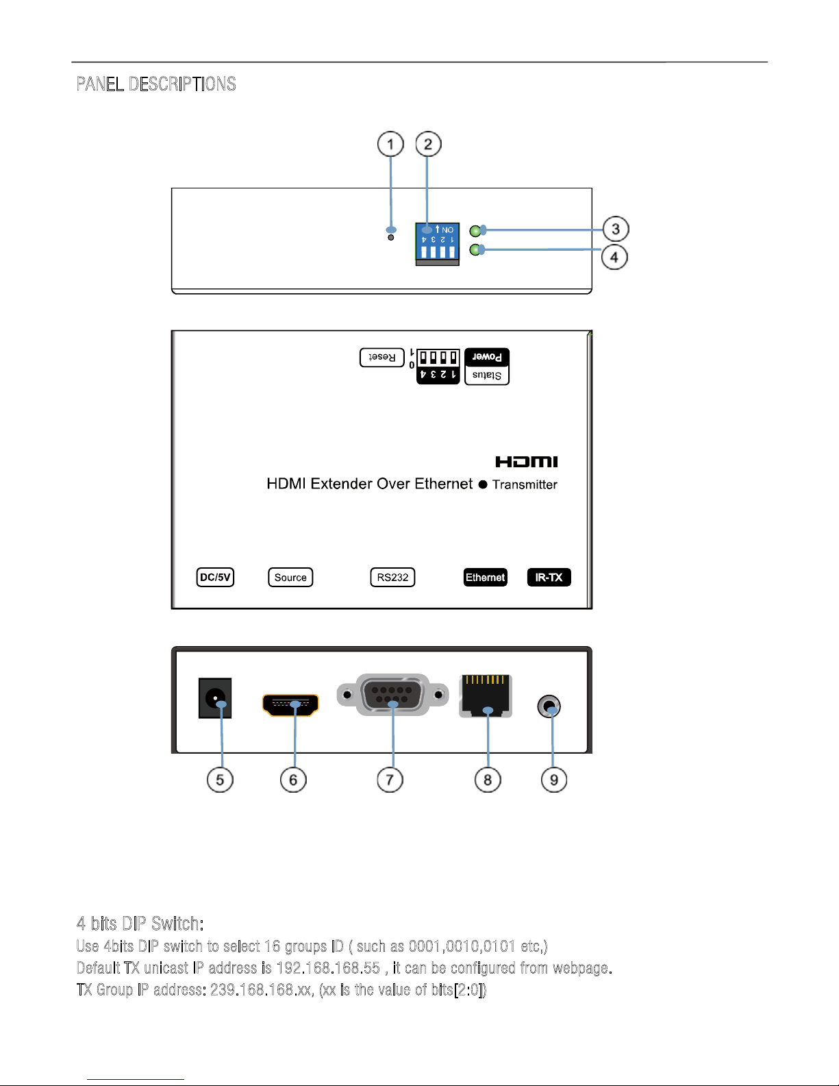
Transmitter Panel
①
Reset button ②
DIP switch
③HDMI input Indicator of power input
④ Status of signal connection ⑤Power input port ⑥HDMI input
⑦
RS232
⑧
Ethernet port ⑨IR-TX port
4
b
it
s DIP Switch:
Use 4bits D
I
P
swit
c
h
to sel
ect 16
g
roups
ID
(
s
uch as 0001,
001
0
,0101 etc,)
D
ef
a
u
l
t
TX unica
st I
P
addre
ss is
19
2.16
8
.168.
55
,
it can be configured from web
p
age
.
T
X Group IP
a
ddres
s
:
2
3
9
.168.168
.xx
,
(
x
x is
the v
alu
e
of bits[2:0])
Operating Instructions
4
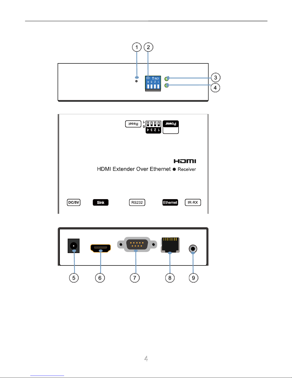
Receiver Panel
① HDMI Output ②
DIP switch ③Indicator of power input
④
Status of signal connection
⑤
Power input port ⑥HDMI Output
⑦
RS232
⑧
Ethernet port ⑨ IR-RX port

Operating Instructions
5
4
b
it
s
D
IP Switch
:
U
se
4bits D
IP switch
t
o
s
e
l
e
c
t 16
gro
u
p
I
D
(
s
u
c
h as
0
0
0
1
,
0
0
1
0
,
0
1
01 etc,)
D
efaul
t
RX
u
n
ica
s
t
I
P
a
ddr
e
ss is 1
9
2.168.1
68.56
, it
c
a
n be conf
ig
ure
d fr
o
m we
b
pa
ge.
R
X Gr
o
u
p
I
P a
ddress:
2
39.168
.
1
6
8
.
X
X
X (
XXX is t
he val
u
e
of bits
[
2:0])
U
s
e
r
s
hou
l
d
co
nfigure the
D
I
P
swi
tch wi
thin 1
0
sec
ond
s, firmware s
h
ould r
e
set the
s
y
stem 20 second after det
ecting
the
fi
rst
c
hange of DIP switch,
and latch th
e new
D
I
P sw
i
t
ch val
ue
a
fter re
s
e
t.
A
ppl
ic
ati
o
n 1:
P
oi
nt to
p
oint
confi
g
u
ratio
n
:
1. Connect one HDMI Cable between the HDMI output port of source device and the HDMI input port of
Transmitter unit
2. Connect one HDMI Cable between the HDMI input port of display and the HDMI output port of Receiver
unit.
3. Connect one UTP Cat5e or better cables between the RJ45 port of Transmitter unit and RJ45 port of
Receiver unit.
4. Connect 5V DC power supplies to both Transmitter unit and Receiver unit.
5. Power on the output device rst and the source second.
P
lea
se
m
ake sure power on the transm
i
t
t
er and
r
e
ceiver first, then power
o
n the source!
HDMI cable
RS232 cable
RS232 cable
IR-TX cable
IR-RX cable
DVD or STB remote
HDMI cable
HDMI Display
HDMI cable
HDMI Source
Transmitter Receiver
Free rotate camera
PC

Operating Instructions
6
A
ppl
icatio
n 2:
O
ne to many
ne
twork co
nfiguration:
1. Connect one HDMI Cable between the HDMI output port of source device and the HDMI input port of
Transmitter unit
2. Connect one CAT5e or better cable between the RJ45 port of transmitter and input port of Gigabit
Ethernet switch hub.
3. Connect one CAT5e or better cable between the output port of each Gigabit Ethernet switch hub and
RJ45 port of Receiver unit.
4. Power on the output device rst and then the source device.
5. If DIP switch of the transmitter is set up: Group ID:0001, then DIP switch for receiver should be set up
Group ID:0001
Important: Please make sure power on the POE switch adopter for TX&RX when
connecting with POE switch rst , then power on the source !
No need power adapter for TX & RX when connecting with POE Switch.
M
odify the
TX and all RX for a different IP &
MAC
address in LAN (l
o
cal
area network)to avo
i
d
c
onflict.
HDMI cable HDMI cable HDMI cable
HDMI cable
Cat5e cable
Cat5e cable
RS232 cable
RS232 cable
RS232 cable
RS232 cable
IR-TX
PS3,Blu-ray DVD player, etc.
HDMI Source
POE
Giga PoE Web smart switch
Transmitter
HDTV
HDTV
HDTV
DVD or STB remote
Receiver
DVD or STB remote
Receiver
DVD or STB remote
Receiver
Free rotate camera Free rotate camera Free rotate camera
PC
IR-RX
HDMI cable
RS232 cable
HDTV
DVD or STB remote
Receiver
Free rotate camera
IR-RX
IR-RX
IR-RX

Operating Instructions
7
A
ppli
catio
n 3:
M
any to M
any net
w
ork
confi
g
uration
:
1. Connect one HDMI Cable between the HDMI output port of source device and the HDMI input port of
Transmitter unit.
2. Connect one HDMI Cable between the HDMI inpu port of display and the HDMI output port of Receiver
unit.
3. Connect one CAT5e or better cable between the RJ45 of each Transmitter unit and RJ45 port of
Gigabit Ethernet switch hub.
4. Connect over each RJ45 port of Gigabit Ethernet switch hub with RJ45 port of Receiver unit.
5. Use DIP switch to select sources, User can select source channel by DIP switch setting on each
transmitter unit and set up DIP switch on each receiver. And select display devices for Receiver units
via one remote control
Important: Please make sure power on the POE switch rst , then power on the
source !
Now
, If you need display Source2 on TV1, then just set Group ID of RX1 0101,same as TX2: 0101 (refer
to Diagram).
1).Use 4-bit DIP switch to select 16 group ID (such as 0001, 0010, 0101 etc.)
When you set up the group ID for each transmitter just like this :
3).For example, when the devices are connection as below :
Source (DVD2) - TX (TX2) - Gigabit Switch - RX(RX2)- TV2
Source (DVD3) - TX (TX3) - Gigabit Switch - RX(RX3)- TV3
Source( DVD1) - TX (TX1) - Gigabit Switch - RX(RX1)- TV1
2).Change group ID easily to select the sources.
Ho
w
to u
se DIP s
w
i
tch:
TX1 (0001)
TX2 (0101)
TX3 (0100)

Operating Instructions
8
No need
power
adapter fo
r TX & RX whe
n connecting
with POE Switch.
M
odify all TX and all RX for a different IP & MAC address in LAN (local area network)to avoid
c
onflict.
HDMI cable HDMI cable
Cat5e cable
Cat5e cable
Cat5e cable Cat5e cable
RS232 cable
RS232 cable
Giga PoE Web smart switch
Giga PoE Web smart switch
HDTV
DVD or STB remote
Receiver
HDTV
DVD or STB remote
Receiver
Free rotate camera
Free rotate camera
IR-RX
IR-RX
HDMI cable
RS232 cable
HDTV
DVD or STB remote
Receiver
Free rotate camera
IR-RX
HDMI cable
RS232 cable
HDTV
DVD or STB remote
Receiver
Free rotate camera
IR-RX
HDMI cable
RS232 cable
IR-TX
PS3,Blu-ray DVD player, etc.
HDMI Source
Transmitter
PC
Group ID:0001
HDMI cable
RS232 cable
IR-TX
PS3,Blu-ray DVD player, etc.
HDMI Source
Transmitter
PC
Group ID:0101
HDMI cable
RS232 cable
IR-TX
PS3,Blu-ray DVD player, etc.
HDMI Source
Transmitter
PC
Group ID:0100
If set Group ID
Then TV1 displays DVD2
same as TX2:0101

Operating Instructions
9
Setup HDMI
T
X and HDMI RX
A HTTP server is embedded in each TX and RX. you can setup IP address for HDMI extender via web
browser.
The default IP address of the T
X
is
192.
168.168.55, MAC a
ddress is: 0
0:0b:78:00:6
0:01
.
The default IP address of the R
X is 192.168.168.56,
M
AC address is: 00:0b:78:00:60:02.
S
tep 1
:
→ Assign the PC (or laptop) IP address on the computer : “Control Panel” ” Network
→→ →Connections” “Local Area Connections Status” “Properties” “Internet Protocol (TCP/IP)”, Type the IP
address eld with 192.168.168.11 (0-255) and Subnet mask with 255.255.255.0. After that press OK
to save the conguration.
Note: The IP address of PC should be different from the IP address of TX and RX.
S
tep 2: Use an Ethernet Cable to connect the PC (or laptop) and the extender. the power LED for the
extender is red and the status LED becomes green.
S
t
ep 3:
→ → please Ping the connected device through the sequence on computer: “Start” “Run” input
→“CMD” input “ping 192.168.168.55” for TX or input “ping 192.168.168.56” for RX, you will receive
the reply if the connection is established.
Step
4:
Login in the IP adress :192.168.168.55 (default IP for TX) or 192.168.168.56(default IP for RX),
You can setup IP address, subnet mask, gateway, and MAC address for the TX and RX.
Please set IP address for each TX and each RX, IP:192.168.168.XX (XX:1-255. all IP address for TX and
RX must be different .
Please set MAC address for TX and RX, MAC:00:0b:78:XX:XX-XX (XX:01-FF), The MAC address for each
TX and each RX must be different .
S
tep 5: After click “Apply” button, the green LED light on the device will go out, you have successfully set
IP address for TX and RX now.
Note: if you need to restore the device to it’s factory default settings, please power on the device, the red
light becomes lighting, waiting about 10 seconds, the green LED light starts working, at this time to press
the reset button about 5-10 seconds, then the green light will go out, you have successfully restored IP
address to factory IP address now.

Operating Instructions
10
RS232 pass throug
h
The TX and RX are with DB-9 connector, TX: Female connector; RX: Male connector.
DB-9 Male(Pin Side) DB-9 Female (Pin Side)
------------- ------------ \ 1 2 3 4 5 / \ 5 4 3 2 1 /
\ 6 7 8 9 / \ 9 8 7 6 /
--------- --------RS-232 Pin Denition
TX PIN Denition PIN Denition
1 NC
2 TxD
3 RxD
4 NC
5 GND
6 NC
7 NC
8 NC
9 NC
RX PIN Denition PIN Denition
1 NC
2 RxD
3 TxD
4 NC
5 GND
6 NC
7 NC
8 NC
9 NC
Baud Rate: 115200(Default)
Data Bit: 8 bits
Parity: None
Stop Bit: 1 bit
Flow Control: None
User can login web site to modify the Baud Rate which range from 1200 to 115200 (login in the IP
address: TX: 192.168.168.55/RX: 192.168.168.56). When sending data, the IP address must be put as
header (eg: If you need send “5A” from RX to TX, the IP address of TX is 192.168.168.55, “CO A8 A8 37”
is the Hex format of IP address 192.168.168.55, then you should send “CO A8 A8 37”; if you need send
“5A” from TX to RX, the IP address of RX
is 192.168.168.56, “CO A8 A8 38” is the Hex format of IP
address 192.168.168.56, then you should send “CO A8 A8 38”;).

Operating Instructions
11
P
RODUCT SERVICE
1) D
a
mage
requiring service: The unit should be serviced by qualied service personnel if:
(a)The DC power supply cord or AC adaptor has been damaged;
(b)Objects or liquids have gotten into the unit;
(c)The unit has been exposed to rain;
(d)The unit does not operate normally or exhibits a marked change in performance;
(e)The unit has been dropped or the cabinet damaged.
2) S
ervicing Personnel: Do not attempt to service the unit beyond that described in these operating
instructions. Refer all other servicing to authorized servicing personnel.
3) R
eplacement
parts: When parts need replacing ensure the servicer uses parts specied by the
manufacturer or parts that have the same characteristics as the original parts. Unauthorized substitutes
may result in re, electric shock, or other hazards.
4) S
a
f
ety
che
ck: After repairs or service, ask the servicer to perform safety checks to conrm that the
unit is in proper working condition.

Operating Instructions
12
WARR
A
N
T
Y
If your product does not work properly because of a defect in materials or workmanship, our Company
(referred to as "the warrantor" ) will, for the length of the period indicated as below, (
P
arts(2)Year,
L
abor(
90) Days
)
which starts with the date of original purchase ("Limited Warranty period"), at its option
either(a) repair your product with new or refurbished parts, or (b) replace it with a new of a refurbished
product. The decision to repair or replace will be made by the warrantor.
During the "Labor" Limited Warranty period there will be no charge for labor.
During the "Parts" warranty period, there will be no charge for parts. You must mail-in your product
during the warranty period. This Limited Warranty is extended only to the original purchaser and only
covers product purchased as new. A purchase receipt or other proof of original purchase date is required
for Limited Warranty service.
M
AIL-
IN SERVI
CE
When shipping the unit carefully pack and send it prepaid, adequately insured and preferably in the
original carton. Include a letter detailing the complaint and provide a day time phone and/or email
address where you can be reached.
L
IMITED
WARR
AN
TY
LIMITS
AND
E
X
CLUS
IONS
1) This Limited Warranty ONLY COVERS failures due to defects in materials or workmanship, and DOES
NOT COVER normal wear and tear or cosmetic damage.
The Limited Warranty ALSO DOES NOT COVER damages which occurred in shipment,
or failures which are caused by products not supplied by warrantor, or failures which result from
accidents, misuse, abuse, neglect, mishandling, misapplication, alteration, faulty installation, set-up
adjustments, misadjustment of consumer controls, improper maintenance, power line surge, lightning
damage, modication, or service by anyone other than a Factory Service center or other Authorized
Servicer, or damage that is attributable to acts of God.
2) THERE ARE NO EXPRESS WARRANTIES EXCEPT AS LISTED UNDER "LIMITED WARRANTY COVERAGE".
THE WARRANTOR IS NOT LIABLE FOR INCIDENTAL OR CONSEQUENTIAL DAMAGES RESULTING FROM
THE USE OF THIS PRODUCT, OR ARISING OUT OF ANY BREACH OF THIS WARRNTY. (As examples, this
excludes damages for lost time, cost of having s
omeone remove or re-install an installed unit if
applicable,
travel to and from the service, loss of or damage to media or images, data or other recorded content. The
items listed are not exclusive, but are for illustration only.)
3) PARTS AND SERVICE, WHICH ARE NOT COVERED BY THIS LIMITED WARRANTY, ARE
YOUR RESPONSIBILITY.
 Loading...