


Professional StationProfessional Station
Professional Station
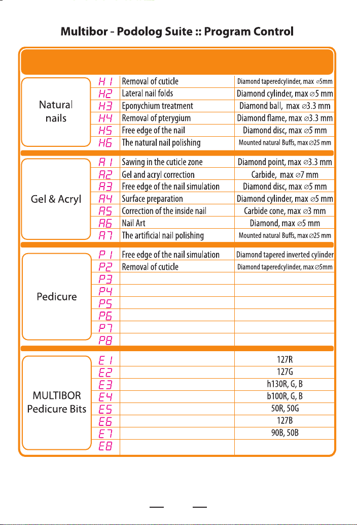
Type
Lateral nail folds
For toes abrading
ToolNameDisplay
Diamond ball, max o3.3 mmEponychium treatment
Diamond ame, max o3.3 mmRemoval of pterygium
Diamond cylinder, max o5 mm
Silicone, max o10 mmThe natural nail polishing
Abrasive, silicone, max o13 mmThe step's skin grinding
Abrasive, silicone, max o9 mm
Very rough heels primary treatment
Rough skin intensive abrading
For a basic step's cracks treatment
On the edge of step cracks treatment
Removing of corns and rough skin on toes
Final foot polish
Lateral nail folds soft abrading
Carbide ball o2 mmRemoval of a corn callus
Please note the following:
The progrms for “MULTIBOR Pedicure Bits” and program for the “Pedicure” are dierent. If you work with replaceable sand caps
based on rubber or with sintered cersmics, please select the “Pedicure” only. If you try to activate the “MULTIBOR Pedicure Bits”,
there is a risk that your tool bends or breaks down/
2

PROFESSIONAL TOOLS
Before getting started, please read this User Guide carefully.
Attention! The device has sucient means of electronic protection,
but no automation is able to provide 100% safety against unjustied,
inept or destructive steps by the User.
Please remember! Before you switch on the rotation, make sure that
nothing stands in its way, the engine is free, there is a tool in the
collet clamp, the collet clamp is locked, and the collet holds the tool
rmly.
Caution! Mechanical defects in the entire device or in separate parts
thereof and absence of its components as well as damaged or burnt
engine or its power cable shall deprive the User of the opportunity of
free repair and shall not impose any warranty obligations upon the
Manufacturer.
Please handle the device with due care and use it as prescribed. Do
not allow for excessive workload and do not use it for operations the
device is not intended for, and it will then serve you very well for
years!
Should you have any questions regarding the use of the device or
should you put the device into such modes of operation where from
you don't know the way out, please contact the Service Center.
Service Center
www.multibor.eu
3
Introduction
Multibor — Podolog Suite is a series of devices from the Podolog
lineup developed under the Multibor-Suite technology intended for
intensive operation with signicant workloads while providing the
entire range of services in the elds of machine-assisted manicure and
pedicure as well as for incrementing, modeling, and correction of
articial nails.
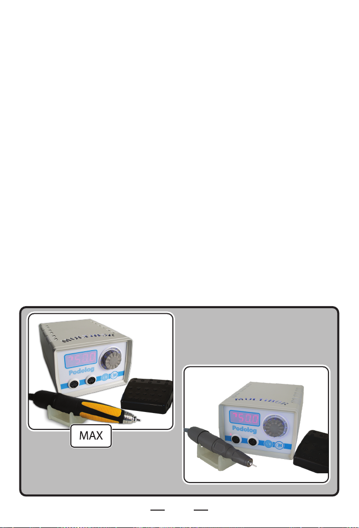
The lineup of devices comprises the following models:
• Multibor – Podolog
• Multibor – Podolog MAX
These models have dierent technical properties and congurations.
Multibor — Podolog Suite is a milling cutter for masters of nail care
(hereinafter, the 'Milling Cutter'). This is a microprocessor unit with
separate programs for dierent types of operations and for dierent
types of tools with automatic selection of preset programs and with
digital adjustment for optimal mode of operation.
4
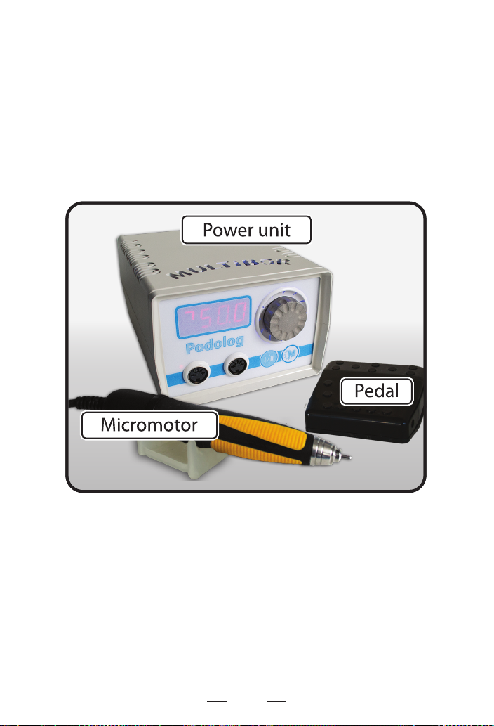
Delivery Set
· Power unit
· Handheld milling cutter (micromotor)
· Micromotor pad
· Pedal (available in specic models)
· User Guide
· Packaging
Safety Precautions
In order to ensure safe operation of the Milling Cutter, please learn
the safety precautions specied in this User Guide. Do not try to use
the Milling Cutter is a manner not specied in this document. Do not
try to use the Milling Cutter for operations not specied in this
document.
5

ATTENTION! Disregarding these safety precautions may damage
the Milling Cutter or may result in its ignition or in electric shock for
you.
ATTENTION! Plug the Milling Cutter in the electric mains thru
standard three-pin sockets with grounded terminals only.
Nine Simple Rules:
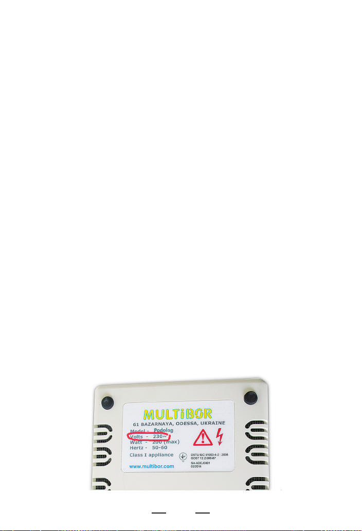
1. Never use electric mains where voltage and frequency are
dierent from the parameters specied on the casing of the Milling
Cutter.
2. Do not try to plug or unplug the Milling Cutter with wet hands.
3. Always insert the plug deeply to the end.
4. Never pull the power cable to withdraw the plug out of the wall
socket.
5. Avoid damage to and do not modify and do not stretch the power
cable and the connection cable. Do not put any items onto them. The
connection cable remains under big workload while in use, therefore
it would quickly break down if used improperly (e.g. knots and loops
in the cable, constant bending at sharp angles, abrupt moves).
6. Do not switch the Milling Cutter on if the power cable or
connection cable is looped or knotted.
7. Do not plug the Milling Cutter in a wall socket, which is used to
provide power to some other equipment (via extension cables,
T-junctions, etc.)
8. Use high-quality and properly operating tools (caps, milling tools,
etc.) only. Shank ends must be plain-shaped and all parts of the tools
must be rmly xed to each other. Do not use any worn tools as it
may result in their destruction.
9. When selecting the operation modes for the Milling Cutter, do not
go beyond the maximum permitted limits for a specic tool as it may
result in destruction of the tool and in breakdown of the Milling
Cutter.
6
Make sure there is some free space around the wall socket, so that
you can quickly unplug the device if necessary. In the event of smoke,
unusual fumes or strange noise near the Milling Cutter, switch it o
immediately, unplug it and refer to the Service Center. Do not place
any items onto the power unit. If any external items or uids get into
the Milling Cutter, unplug it o immediately and contact the
technical
ATTENTION! It is prohibited to disassemble or modify any
components of the Milling Cutter. Several parts of the power unit
bear high voltage. It is not allowed to perform any maintenance
procedures not specied in this User Guide.
Do not use any ammable spays near the Milling Cutter.
Do not keep any ammable uids near the Milling Cutter.
Do not place the Milling Cutter in locations with high humidity or
dust or smoke contents and in locations under direct sunlight as
well as in the vicinity of heating equipment.
The voltage and frequency of the power supply mains
are shown on the device!
7
Description and designation of the major components
Power Unit
This is a microprocessor-based power supply unit for direct current
micromotors able to quickly adjust their operation modes. The
power unit is designated for the operation jointly with the handheld
milling cutter.
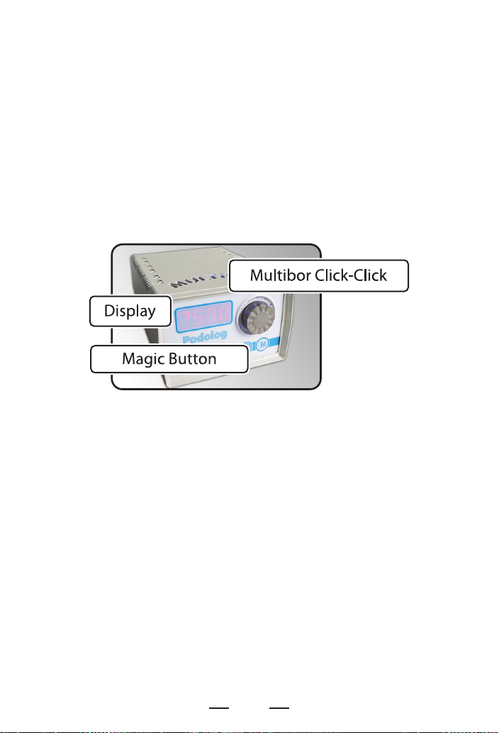
The controls and signal functions of the power unit have several
unique features based on the unique technologies by Multibor
Company, and namely:
- Multibor Click-Click manipulator
- Multibor Magic Button switch
Thru the 'Multiobr Click-Click' (hereinafter, the 'Manipulator'), it is
possible to:
- switch the rotation on or o
- increase or decrease the rotation speed
- change the rotational direction: 'Reverse' function
- select a control program from the list
Thru the 'Multibor Magic Button' (hereinafter, the 'M-button'), it is
possible to:
- activate the program control mode
- deactivate the program control mode
Attention! When in the program control mode, such parameters as
output power, maximum torque, protection operating level and the
like are automatically selected and adjusted by the processor in
accordance with the preset algorithms and thus cannot be altered by
the user.
8

The light warning system comprises the Display and the range with
12 light emission diodes (LED Range) (like a clock face) located
around the Manipulator.
The light warning system is further assisted by the audible warning
system.
Handheld Milling Cutter
The handheld milling cutter has the shape of a monoblock unit. The
unit looks like a ball pen conveniently sitting in one's hand and
making it possible to easily set and use the standard tools.
The manufacturer supplies the handheld milling cutters certied
under ISO 9001 and guarantees the high-quality performance of the
device only with them.
Setting and changing the tools
The tools are set by turning the clamp control grip on the handheld
milling cutter up until a click is heard:
Leftwards - the tool clamp is open
Rightwards - the tool clamp is locked
9

The shank end of a tool must be set into the clamp deeply until
locked. Another manner of tool setting leads to vibration, to
accelerated wear of the clamp and of the handheld milling cutter,
and to damage to the tool. Such operation of the Milling Cutter along
with the usage of unbalanced tools (vibration while operating the
handheld milling cutter) results in the loss of the warranty rights for
the user.
Changing the tools
1. Switch o the tool rotation
2. Wait until the tool rotation stops completely
3. Use your hands to
move the clamp lock
into the 'R' direction.
4. You must hear
a distinctive click
5. Extract the old tool
6. Set the new tool
into the clamp
7. Use your hands
to move he clamp lock
into the 'S' direction
until a distinctive click is heard
10

Changing the tools in the MAX congurations
1. Switch o the tool rotation
2. Wait until the tool rotation stops completely
3. Use your hands to
turn the upper part
(orange color) into the
"A" direction over 2
clicks. One click is not
enough since this is an
intermediate position
4. Click twice until locked in
5. Extract the old tool
6. Set the new tool
into the clamp
7. Turn the clamp lock into the "B" direction over two clicks
Pedal
The pedal is intended for activating and deactivating the rotation
function with the help of a foot. Depending on the conguration
option, the pedal may sometimes not be a part of the equipment
supplied. However, users can purchase the pedal as a separate piece
of equipment.
11

Preparing for work
1. Unpack the Milling Cutter. If the device is brought from a cold
place to a warmer place, it should be unpacked not earlier than after
two hours.
2. Place the power unit onto a plain, rigid, and stable surface such as
a working desk. Select a position of the power unit in such a manner
that its front panel can be seen in full and its controls can be easily
accessed. Place the pod in the immediate vicinity of the power unit.
3. Connect the power cable plug of the handheld milling cutter to
the relevant jack at the front panel of the power unit.
Attention! The plug has a ping and the jack has an inlet. This is the
key to the correct connection; the relevant ping should get into the
relevant inlet.
4. Check if there is a tool or a standard temporary cover in the collet
clamp of the handheld milling cutter.
5. Never forget to make sure that the collet clamp is locked and that
the collet holds the tool rmly and does not let it fall out.
6. Take the tool with your ngers carefully and turn the shaft of the
handheld milling cutter a few times. Make sure that the tool can
rotate together with the collet and that the rotation is done freely
without external noise and vibration.
7. Put the handheld milling cutter onto the pod in such a manner
that it does not block your access to the front panel of the power
unit.
Attention! It is not recommended to put the handheld milling cutter
as well as any other tools and caps onto the upper lid of the power
unit. Use the pod instead.
8. Plug the power cable in the wall socket.
9. The milling cutter is now ready for work.
12

Work Sequence
Power Up
Attention! When powered up, the milling cutter will maintain the
same operation mode and the same adjustments that were in eect
at the power down moment. There is no need to recall and set the
operation modes again. This memory is independent from any
operation mode.
Switch the power unit on, having set the power supply switch at the
back panel from the '0' position to the 'I' position.
This will activate the self-test of the Milling Cutter and it will be
indicated in the form of 'running lights' at the LED Range and in the
form of 'running eights' at the Display. As the 'running eights' fade
away in combination with the 'running sequence of lights' and as a
single audible signal is heard, it tells us that the self-test is completed
and that the equipment is ready for work if the following conditions
are fullled:
1. The 'MULTIBOR' sign at the upper lid of the casing is
illuminated with constant blue light
2. No breakdown alarm is heard
3. No 'Pedal is out of order!' indication is shown at the Display
13

Such signal may be caused by
mechanical or electrical faults
in the pedal itself as well as in its
power cable or control circuit.
For example:
1. Foreign items are on the pedal when it is powered up
2. The contacts in the pedal have stuck together and thus
always remain in the short-circuit position.
3. The pedal power cable has been worn out to the end, broken
down or destroyed
In order to x the problem caused by such a signal, the following
steps must be taken:
1. Remove the foreign items from the surface of the pedal
2. Press the pedal a few times to check the mechanical
intactness of contacts
3. Disconnect the pedal from the power unit and continue
working without the pedal
A fault in the electronic components
of the power unit may cause such a
signal to go on.
In case such signal is on, the
following must be done:
1. Stop the operation
2. Unplug the milling cutter
3. Contact the Service Center

Modes of Operation
Indications and Alarms in Dierent Modes
The handheld milling cutter can operate in two equivalent modes:
Manual mode
Program mode
For each of the modes, each type of indication is shown at the display
by means of a relevant combination of characters, digits, and
segments, and is also backed up by specic audible signals
In any mode, prior to switching on the tool rotation, its direction is
shown by an arrow on the Display.
If the arrow goes upwards
and to the right, the tool
will rotate clockwise.
If the arrow goes downwards
and to the left, it means that
the "Reverse" function is
activated and the tool will
rotate counterclockwise.
15

Manual Mode
Switching between the manual and program modes is performed by
pressing the 'M-button' and is followed by an audible signal.
Switching between the modes is only possible when the tool
rotation is o.
In the Manual mode, the display shows only two or three digits,
which mean the tool rotation speed in thousands of revolutions per
minute (rpm).
Speed 9,700 rpm
“Reverse” - OFF
The rotation direction is shown by the "running arrow" in the rst
section of the indicator on the Display.
Attention! The weight and mechanical balance of a tool have
signicant inuence on the vibration of the milling cutter. There is a
risk of damaging a tool at the speeds exceeding 30,000 rpm. The
milling cutter has two levels of rotation adjustment in order to
decrease the probability of accidents.
1. Fast and abrupt adjustment done literally during a single
revolution of the Manipulator for the speeds of up to 30,000
rpm only. In this case, a short audible signal indicates that the
rst level speed is reached.
2. The increase of the speed exceeding 30,000 rpm will be done
slower. Actually, the Manipulator needs to be rotated for a
longer time while the speed increases slower.
Speed 25,300 rpm
“Reverse” - ON
16

1. To switch on the rotation, press the center of the Manipulator
once
2. To increase the rpm rate, rotate the Manipulator clockwise
3. To decrease the rpm rate, rotate the Manipulator counterclockwise
4. To alter the rotational direction (the reverse function), press the
center of the Manipulator twice at a run same as you double-click on
a computer mouse
5. To switch o the rotation, press the center of the Manipulator once
again
You can change the rpm rates and the rotational directions
on the go.
17

Program Control Mode "Programs"
Press the 'M-button' to select operation modes under the preset
programs.
While in the 'Programs' mode, the display shows a character to
indicate a specic program and a digit to indicate the program's
number.
Program H6
“Reverse” - OFF
Select a desired program by rotating the Manipulator.
Press the center of the Manipulator for one time to start the rotation.
Attention! The rpm rates and the programs cannot be changed on
the go. Stop the rotation to change a program. While a program is in
operation, it is only possible to change the rotational direction by
pressing the center of the Manipulator for two times at a run same as
you double-click on a computer mouse.
Program P7
“Reverse” - ON
Very important! Follow the safety precautions!
It is allowed to unlock the clamp or to change a tool only after the
rotation is fully stopped.
18

Multibor - Suite technology
The quality and the speed of performance of the procedures depend
both on the skills of a master and on the correct combination of the
equipment and materials as well as on the output power of the
milling cutter, the shapes and sharpness of the caps, the tool rotation
speed, and the pressure on the nail plate or the foot of a client. The
Multibor-Suite technology combines the technical capabilities of the
equipment, the specics of usage of the tools for machine-assisted
nail care, the present-day requirements of a client, and the skills of a
master. Your milling cutter operates according to the Multibor-Suite
technology in the Program Mode. This enables you to use the table
for correct operation of the device in accordance with a pre-selected
program for a specic procedure. The processor will further
automatically select the required speed, the output power, and the
torque, and it will also supervise and control all required changes in
the course of the operation, smoothly adapting to your manner of
performing the procedure.
The additional opportunities of Multibor-Suite
It is only the MULTIBOR Suite Podolog device family that has two
control channels and two connections for two engines, which can be
controlled in turns. This feature would for instance be useful for
chiropodists.
Thru the usage of the additional engine of the NAIL type jointly with
the "Natural Nail" or "Pedicure" programs, it can select the operating
modes for complex podiatric cases.
Besides, MULTIBOR Company can supply the Podolog-type devices
with additional therapeutic engines required for the operation with
the Omnicut heads under the mechanical nail care technology with
cuticles trimmed.
Attention! The Omnicut head is not included in the package.
This tool should be purchased separately.
19

Multibor - Power Control Processor technology
The power control processor precisely controls the correlation of the
selected rpm rate with the output power required to perform a
specic procedure or a type of work. When the nail care master
presses the tool rmer to the surface being treated, the Milling Cutter
does not stop and does not decrease the preset rpm rate; on the
contrary, it keeps those parameters as they are, while overcoming the
resistance of the surface being treated. However, any type of work
has its own precisely limited range of the output power applied.
When the nail care master approaches the permitted limits of the
output power in the course of work, the power control processor
sends an audible warning signal. The nail care master should then
change the working pressure or else the power control processor
would switch o the power supply to the motor. This enables the nail
care master to 'limit the working pressure' and to use the power
reserve more precisely, thus making it possible to prolong the
technological lifespan of the Milling Cutter and to keep it from
overheating under 'hard operation modes' and sustained workloads.
The graph shown below will assist you with better understanding
when you need to select the required speed of rotation depending
on the diameter of the tool applied.
20

Emergency Protection
In order to preclude incorrect steps and to protect the equipment
from damage, the Milling Cutter has an emergency protection
system. When the emergency protection system is activated, an
audible signal is heard and an error message is shown at the display.
The 'Overload' indication means that
the tool applied is being used at a speed
or with a power rating not allowed for
such a tool.
To deactivate the 'Overload' emergency
mode, the following must be done:
1. Switch o the rotation
2. Select the correct speed (Manual
Mode)
3. Select the correct program (Program Mode)
4. Select the correct tool (any of the modes)
5. Resume the operation
In the event of the micromotor overheating, switch o the Milling
Cutter for 30 minutes and then resume the operation.
The 'No Motor' signal means that there
is no power supply to the handheld
milling cutter.
This may be caused by a number of
reasons:
- No connection to the handheld milling
cutter
-- No electric contact in the output jack
of the power unit
- Damaged power cable of the handheld milling cutter
- Breakdown of the brushes in the motor of the handheld milling
cutter
It is allowed to independently deactivate the 'No Motor' emergency
mode only if the handheld milling cutter is not powered up.
In all other cases, please refer to the Service Center to correct any
faults.
21

The 'Open Collet' signal means that there has been an attempt to
switch on the rotation without a tool or with an open collet clamp.
In order to deactivate the 'Open Collet'
emergency mode, the following must
be done:
1. Switch o the rotation
2. Insert a tool
3. Lock the collet clamp
4. Resume the operation
Pedal Operation
Connect the relevant plug of the pedal to the relevant jack at the
back panel of the power unit and place the pedal in a location
suitable for work. Press and hold the pedal with your foot to start the
rotation of a tool. Release the pedal to stop the rotation.
Attention! The pedal only reacts to closure and opening of the
electric contacts. No changes occur to the rotation speed of a tool.
Maintenance
Very important! All types of preventive maintenance must be
performed only when the Milling Cutter is disconnected from the
power supply and unplugged from the wall socket! An accidental
switch-on of the Milling Cutter during maintenance may result in
injury, electric shock or damage to the device.
Prior to any operation of the Milling Cutter, always check the casings
of the power unit and of the handheld milling cutter, the connection
cables, and the power cable. If any damage is found, contact the
Service Center for replacement.
WARNING! Operation of the device is prohibited until the damaged
parts are duly replaced!
22

Name OperationDisplay
power unit
malfunction
Pedal is out
of order
No Motor
Open Collet
Overload
1. Stop the operation
2. Unplug the milling cutter
3. Contact the Service Center
1. Remove the foreign items from
the surface of the pedal
2. Disconnect the pedal from
the power unit and continue
working without the pedal
1. Check the connection of the motor
2. Please refer to the Service Center
1. Switch o the rotation
2. Insert a tool
3. Lock the collet clamp
4. Resume the operation
1. Switch o the rotation
2. Select the correct speed, program
or tool
3. Continue operation

 Loading...