

200 | 400 | 800 Ws
END ES F IT
USER’S GUIDE
2
USER’S GUIDE.
PROFILUX PLUS
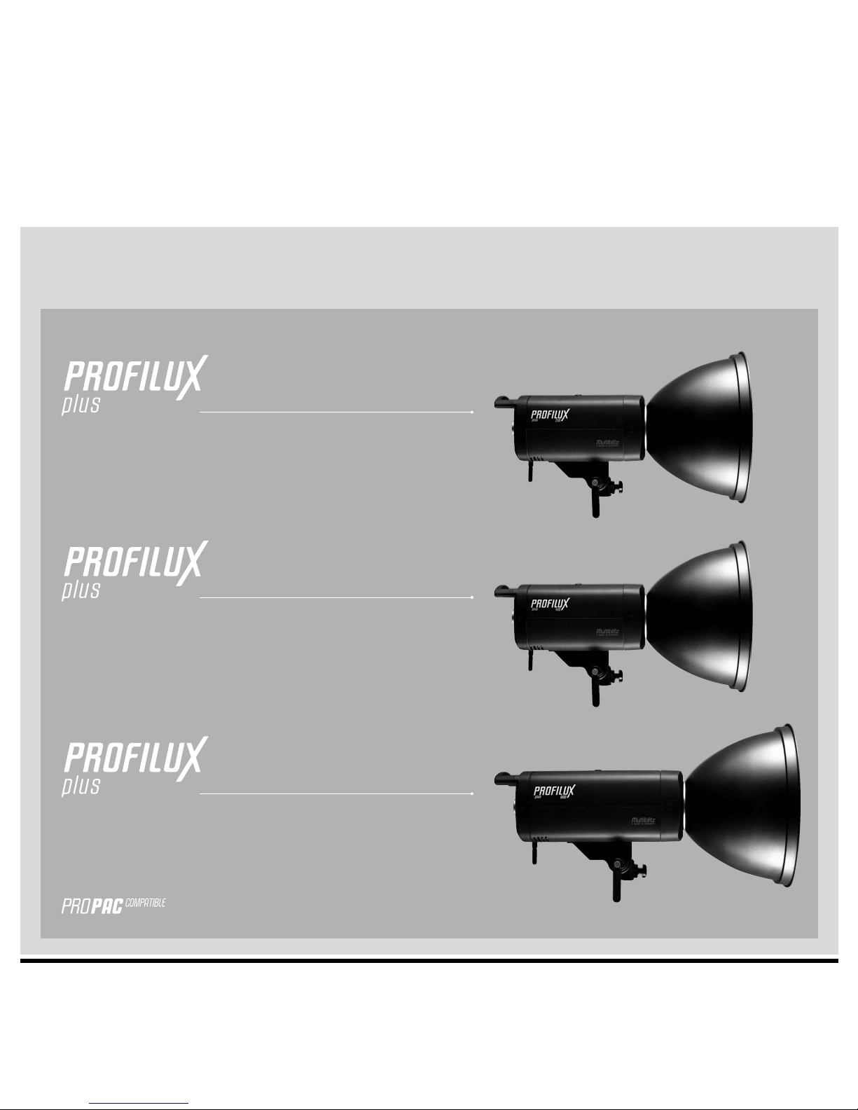
RANGE
200 Ws
400 Ws
800 Ws
3
Thank you for choosing MULTIBLITZ, we hope you enjoy working with this high quality
product. MULTIBLITZ flash units are designed and manufactured without exception in
Germany.
CAUTION!
Please read the instruction manual carefully before using this product.
Flash-/ and halogen tubes as well as metal parts can become very hot during
operation and may cause burns if not properly handled.
Opening the unit could be extremely dangerous!
Do not open the unit by yourself!
Service should only be executed by an authorized MULTIBLITZ service location.
Do not obstruct the venting slots.
Do not place filters, diffusing materials, or any other obstructions directly onto
the flash-/ and halogen tubes.
Do not expose the unit to water (spray-/ or dripping water)
Do not run the PROFILUX PLUS with gasoline or diesel generators.
Use exclusively with Multiblitz battery packs or mains voltage.
This unit should be serviced once a year by an authorized MULTIBLITZ service
location.
The crossed out wheeled bin label that can be found on your product indicates that
this product should not be disposed of via the normal household waste stream.
To prevent possible harm to the environment or human health please
separate this product from other waste streams to ensure that it can
be recycled in an environmentally sound manner. For more details on
available collection facilities please contact your local government
office or the retailer where you purchased this product.
In order to avoid excessive concentration of ozone produced by using strong flash
devices, it is necessary to ventilate confined spaces regularly.
The minimum distance of 0.3m to the illuminated area must be strictly
maintained.
Protection glases has to be replaced in case of damage.
EN
Vielen Dank, dass Sie sich für Multiblitz entschieden haben. Wir hoffen, dass Ihnen
die Arbeit mit diesem hochwertigen Qualitätsprodukt Freude bereiten wird. MULTIBLITZ
Blitzgeräte werden ohne Ausnahme in Deutschland entwickelt und hergestellt.
ACHTUNG!
Lesen Sie diese Bedienungsanleitung genau durch, bevor sie dieses Produkt
anwenden. Die Blitz-/ und Halogenröhren sowie Metallreflektoren werden
im Betrieb sehr warm und können bei nicht sachgerechter Handhabung Verbrennungen verursachen.
Das Öffnen des Gerätes könnte lebensgefährlich sein!
Öffnen sie das Gerät unter keinen Umständen selber!
Der Service sollte nur von einer autorisierten MULTIBLITZ Vertragswerkstatt
durchgeführt werden.
Decken Sie nicht die Ventilationsschlitze ab. Setzen Sie niemals Filter, DiffusorMaterial oder ähnliches direkt auf die Blitz-/ oder Halogenröhre.
Das Gerät darf auf keinen Fall Wasser oder Feuchtigkeit ausgesetzt werden.
Der Kontakt mit Spritz- oder Tropfwasser ist möglichst zu vermeiden.
Die PROFILUX PLUS Geräte dürfen nicht mit Benzin- oder Dieselgeneratoren
betrieben werden. Die Geräte sind ausschließlich mit einem Multiblitz Akku
oder Netzspannung zu betreiben.
Zur Vermeidung einer möglichen Beeinträchtigung der Umwelt oder der
menschlichen Gesundheit darf dieses Produkt nicht in den Hausmüll
gegeben werden, um zu gewährleisten, dass es in einer umweltverträglichen Weise recycelt wird. Wenden Sie sich für Informationen
zu Entsorgungseinrichtungen an die zuständige Behörde oder das
Geschäft, in dem Sie dieses Produkt erworben haben.
Um eine unzulässige Ozonkonzentration, die durch Verwendung
von starken Blitzgeräten entsteht, zu vermeiden ist es notwendig geschlossene
Räume regelmäßig zu lüften.
Bitte achten Sie darauf, dass Sie den Mindestabstand von 0,3m
zu der zu erhellenden Fläche unbedingt einhalten
Beim Arbeiten mit der Halogenröhre PACHAL unbedingt das Pyrex-Schutzglas
benutzen. Sollte es beschädigt sein muss es umgehend ersetzt werden.
Das Gerät sollte einmal jährlich in einer autorisierten MULTIBLITZ Vertragswerkstatt überprüft werden.
D

4
USER’S GUIDE.
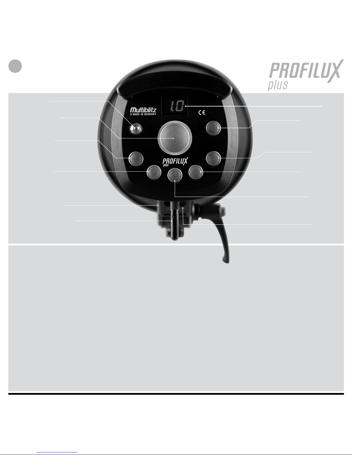
Fotozelle
Leistungsregler
Kanal- und ID Anwahl für
Funkempfänger
Akkustische-/
optische Abblitzkontrolle
Aktivierung der Geräte ID
Test
Handauslöser -TEST-
Aktivierung des Funkempfängers
Synchronbuchse
Antenne/Funkempfänger
Display
Leistungsanzeige
Kanalanzeige Funkempfänger, ID-Anzeige Funkempfänger
Anzeige Funkempfänger “aktiv”
IR Empfänger/Fotozelle An/Aus,
Aktivierung “Pre-Flash Eliminator”,
Anzeige Pre-Flash Eliminator „aktiv“
Halogen An/Aus
(An = Proportional)
Halogenlicht
„Auto-Off“ Anzeige
Gerät An/Aus
Halogenlicht 100%
An/Aus
Halogenlicht
„Auto-Off“ Anzeige
Sicherungslade/
Ersatzsicherung
WICHTIGE HINWEISE!
1. Lesen sie unbedingt den Multiblitz Propac „Quick Start Guide“ sorgfältig
durch, bevor sie ein Profilux Plus Gerät netzunabhängig an einem Propac
Akku betreiben.
2. Die entsprechende Halogenröhre ist je nach Land (100 - 130 V oder
220 -240 V) im Lieferumfang des Geräts enthalten. Um eine korrekte
Farbwiedergabe des Einstelllichts zu garantieren, empfehlen wir die
Halogenröhrenspannung der Netzspannung/Akkuspannung anzupassen.
Die entsprechenden Halogenröhren, sofern nicht im Lieferumfang enthalten,
sind über ihren Multiblitz Händler erhältlich.
Betrieb mit 220 - 240 V Netzspannung:
Profilux Plus 200, 70 W Halogenröhre (Code: PROHAL)
Profilux Plus 400, 150 W Halogenröhre (Code: LUHAL 2)
Profilux Plus 800, 205 W Halogenröhre (Code: LUHAL 3)
Betrieb mit 100 - 130 V Netzspannung/
Akkubetrieb (siehe „Propac Quick Start Guide“):
150 W Halogenröhre (Code: PACHAL)
Pyrex-Schutzglas (Code: PLUSKLA)
3. Es ist unbedingt notwendig beim Wechseln vom Akkubetrieb in den
220 - 240 V Netzbetrieb bzw. Wechseln zwischen dem 100 - 130 V
Netzbetriebin den 220 - 240 V Netzbetrieb die Halogenröhre auszutauschen.
100 - 130 V Netzbetrieb auf 220 - 240 V Netzbetrieb:
Wechseln der Halogenröhre PACHAL auf PROHAL, LUHAL 2 oder LUHAL 3.
Akkubetrieb mit Propac-1 oder -2 auf 220 - 240 V Netzbetrieb:
Wechseln der Halogenröhre PACHAL auf PROHAL, LUHAL 2 oder LUHAL 3.
Beim Wechseln vom Akkubetrieb mit Propac-1 oder -2 auf 100 - 130 V
Netzbetrieb und umgekehrt ist kein Austauschen der Halogenröhren
notwendig, da die hier genutzte Halogenröhre PACHAL für beide Betriebsarten
vorgesehen ist.
4. Im Akku-Betrieb mit einem Propac kann mit Einstell-Licht gearbeitet
werden. Um Akkuenergie zu sparen, schaltet sich das Einstell-Licht
automatisch nach 15 sek. ab falls nicht abgeblitz wird, sobald sich
das Einstell-Licht ausschaltet, blinkt der Schalter „Halogenlicht An-Aus“
(der Schalter „Halogenlicht 100%“ ebenfalls, wenn zugeschaltet).
Das Einstell-Licht schaltet sich wieder ein, sobald das Gerät wieder
abgeblitzt oder die Leistung geregelt wird, der Schalter „Halogenlicht
An-Aus“ leuchtet dann wieder permanent (der Schalter „Halogenlicht
100%“ ebenfalls, wenn zugeschaltet).
D

5
PROFILUX PLUS
BEDIENUNGSANLEITUNG
1. Inbetriebnahme
Nehmen sie die Schutzkappe vom Gerät ab indem sie das Reflektor-
Schloss an der Unterseite des Geräts in Richtung des Bedienungs-Panels
schieben, dann die Schutzkappe gegen den Uhrzeigersinn drehen und
herausnehmen.
2. Halogenröhre
Setzen sie die mitgelieferte Halogenröhre in das Gerät ein.
3. Netzanschluss
Verbinden sie das Gerät über das mitgelieferte Netzkabel mit einer Steckdose,
der Schalter „I-0“ glimmt rot und das Gerät befindet sich im „standby”
Modus. Gerät mit dem Schalter „I-0“ einschalten, der Schalter „I-0“
leuchtet rot und das Gerät ist betriebsbereit.
4. Funk-Synchronisation
Die Blitzauslösung des Geräts kann über einen Funkauslöser (Code: RS2/
TRIGGER HAPPY/ TRIGGER ONE, separat erhältlich) erfolgen. Hierbei wird
der Funkauslöser auf den Blitzschuh der Kamera aufgesteckt. Das Gerät/die
Geräte blitzt/blitzen dann synchron beim Auslösen der Kamera ab.
Bitte entnehmen sie Informationen zur richtigen Handhabung des
Funkauslösers der entsprechenden Bedienungsanleitung.
Programmierung der Empfangskanäle:
Im Gerät ist ein 16 Kanal Funkempfänger fest eingebaut, Sender/Funkauslöser (RS 2/ TRIGGER HAPPY/ TRIGGER ONE) und der im Gerät integrierte
Empfänger müssen auf denselben Kanal eingestellt werden. Mit folgender
Tastenkombination kann der Funkempfänger aktiviert und auf den gewünschten Empfangskanal eingestellt werden:
- Die „Test“ Taste ca. 3 sek. gedrückt halten, das Gerät blitzt einmal ab,
das Symbol für die Kanalanwahl „CH“ erscheint auf dem Display, jetzt
muss die Taste wieder losgelassen werden.
- Nach ca. 2 sek. wechselt das Display mit einem kurzen akustischen Signal
von „CH“ nach „--“ (= Funkempfänger nicht aktiv, kein Kanal eingestellt),
da ab Werk kein Empfangskanal eingestellt und der Empfänger nicht aktiv
ist.
- Durch Drehen des Leistungsreglers kann jetzt der gewünschte Empfangs kanal (z.Bsp. „12“ = Kanal 12) eingestellt werden. Die Anwahl des Kanals
durch Drücken der „Test“ Taste bestätigen, das Display wechselt wieder zur
Leistungsanzeige.
- Der Funkempfänger ist jetzt aktiv und arbeitet nun auf dem angewählten
Empfangskanal.
Wechseln zwischen Empfangskanälen:
- Die „Test“ Taste ca. 3 sek. gedrückt halten, das Gerät blitzt einmal ab,
das Symbol für die Kanalanwahl „CH“ erscheint auf dem Display, jetzt
muss die Taste wieder losgelassen werden.
- Nach ca. 2 sek. wechselt das Display mit einem kurzen akustischen
Signal von „CH“ auf den eingestellten Kanal (z.Bsp. „07“ = Kanal 7),
durch Drehen des Leistungsreglers kann jetzt ein anderer Empfangskanal
(z.Bsp. „15“ = Kanal 15) eingestellt werden. Die Anwahl des Kanals
durch Drücken der „Test“ Taste bestätigen, das Display wechselt wieder
zur Leistungsanzeige.
- Der Funkempfänger ist weiterhin aktiv und arbeitet nun auf dem neu
angewählten Empfangskanal.
5. Synchronisation über Kabel
Das mitgelieferte Synchronkabel (Code: MASYG) in die Synchronbuchse
einstecken und mit der Kamera verbinden. Beim Einsatz mehrerer Geräte
genügt der Anschluss eines Gerätes, alle anderen lösen verzögerungsfrei
über den eingebauten IR Empfänger/die Fotozelle aus. Hierbei müssen
die IR Empfänger/die Fotozellen aller genutzten Geräte aktiv sein.
6. Optische-Synchronisation
1. Das Gerät kann auch ohne Synchronkabel durch einen IR Fernauslöser
(Code: MUSEN, separat erhältlich) ausgelöst werden.
Hierbei wird der Fernauslöser auf den Blitzschuh der Kamera aufgesteckt,
der IR-Empfänger/die Fotozelle des Geräts muss über die entsprechende
Taste angeschaltet werden. Das Gerät blitzt dann synchron beim Auslösen
der Kamera ab. Beim Einsatz mehrerer Geräte müssen die IR-Empfänger/
die Fotozellen aller genutzten Geräte aktiv sein.
2. Im Gerät ist ein Pre-Flash Eliminator eingebaut der dazu dient, dass
sich das Gerät auf den Hauptblitz einer Kamera und nicht deren Vorblitz
(Mess-/„rote Augen“ Blitz) synchronisiert, falls man das Gerät optisch mit
einem Aufsteckblitz oder dem eingebauten Blitz einer Kamera auslösen
möchte (z.Bsp. als Aufhellblitz):
- Die Taste „Fotozelle An/Aus“ ca. 3 sek. gedrückt halten, „PF“ erscheint
auf dem Display, jetzt die Taste wieder loslassen, ein kurzes akustisches
Signal ertönt.
- Jetzt muss die Fotozelle des Geräts aus einem Abstand von ca. 2 m
innerhalb von 10 sek. mit dem Kamerablitz (inkl. Vorblitz) angeblitzt
werden.
- Die Taste „Fotozelle An/Aus“ blinkt nun stetig, das Gerät hat „gelernt“
und befindet sich im Pre-Flash Modus, es synchronisiert sich nun zum
Hauptblitz der Kamera.
Um den Pre-Flash Modus wieder zu verlassen, wiederholen sie den
Programmiervorgang, jedoch ohne das Gerät mit dem Kamereablitz
anzublitzen. Die Fotozelle ist nach der Deaktivierung des Pre-Flash
Elimnators immer ausgeschaltet und muss ggf. wieder eingeschaltet
werden.
7) Funkfernbedienung / Vergabe Geräte ID:
Alle Funktionen der PROFILUX PLUS Geräte können mit einer Funkfernbedienung
(TRIGGER HAPPY, separat erhältlich) ferngesteuert werden. Mit dieser Funkfernbedienung können bis zu 16 Geräte individuell angesteuert und einge stellt
werden. Bevor Sie die Geräte voll fernsteuern können, muss den Geräten eine ID
und ein CHANNEL zugeordnet werden.
Mit der „Akustische -/optische Abblitzkontrolle“ Taste lässt sich dem Gerät
eine ID zu ordnen:
- Die Taste „Akustische -/optische Abblitzkontrolle ” ca. 3 sek. gedrückt
halten, „ID“ erscheint im Display. Durch Drehen des Leistungsregler kann
dem Gerät nun eine ID (von 1-16) zugeordnet werden. Die eingestellte ID
erscheint im Display.
- Durch kurzes Drücken der „akustische-/optische Abblitzkontrolle“ Taste
wird die Eingabe bestätigt, es ertönt eine kurzes akustisches Signal.
Eine ausführliche Beschreibung für das Arbeiten mit einer Funkfernbedienung
entnehmen Sie bitte entsprechender Anleitung.

6
USER’S GUIDE.
PROFILUX PLUS
FAQ
Ist es notwendig die 220-240 V Halogenröhre (PROHAL, LUHAL 2 oder LUHAL 3,
im Lieferumfang für 220-240 V Länder enthalten) gegen eine 100-130 V
Halogenröhre (PACHAL, im Lieferumfang für 100-130 V Länder enthalten) auszutauschen, wenn ich reise und von 220-240 V Netzbetrieb in den Netzbetrieb
mit 100-130 V wechsle?
Aus technischen Gründen ist das austauschen der Röhren nicht notwendig,
da die Röhre nicht beschädigt werden würde. Um jedoch eine korrekte Farbwiedergabe zu garantieren, empfehlen wir die Röhren für den praktischen
Gebrauch auszutauschen. Benutzen sie außerdem das Pyrex-Schutzglas
PLUSKLA wenn sie mit der 100-130 V Halogenröhre PACHAL arbeiten.
Ist es notwendig die 100-130 V Halogenröhre (PACHAL, im Lieferumfang für
100-130 V Länder enthalten) gegen eine 220-240 V Halogenröhre (PROHAL,
LUHAL 2 oder LUHAL 3, im Lieferumfang für 220-240 V Länder enthalten) auszutauschen, wenn ich reise und von 100-130 V Netzbetrieb in den Netzbetrieb
mit 220-240 V wechsle?
Ja, dies ist absolut notwendig da sonst die 100-130 V Halogenröhre
beschädigt wird.
Warum muss ich das Pyrex-Schutzglas PLUSKLA benutzen wenn ich mit
der 150 W/100-130 V Halogenröhre PACHAL arbeite?
100-130 V Röhren mit b15 Sockel verfügen nicht über eine eingebaute
Sicherung, deshalb muss das Pyrex-Schutzglas benutzt werden. 220-240 V
Röhren mit b15 Sockel verfügen über eine eingebaute Sicherung.
Warum funktioniert die Auslösung des Geräts mit meinem RS 2 Funkauslöser oder
einer Funkfernbedienung (TRIGGER HAPPY/ TRIGGER ONE) nicht?
Überprüfen sie ob der Empfangskanal des Geräts mit dem Sendekanal des
Funkauslösers übereinstimmt und ob der Funkempfänger im Gerät aktiviert
ist. Siehe Punkt 4.
Warum funktioniert die komplette Steuerung mehrerer Geräte mit einer TRIGGER HAPPY/
TRIGGER ONE Funkfernbedienung nicht?
Überprüfen Sie ob Sie den Geräten individuelle ID’s und CH zugeordnet haben.
Nur durch die Vergabe von individuellen Geräte ID’s lassen sich mehrere Geräte
mit einer Funkfernbedienung adressieren und voll fernsteuern. Siehe Punkt 7.
(Funkfernbedienungen TRIGGER HAPPY separat erhältlich)
Warum funktioniert die Auslösung des Geräts mit meinem MUSEN
Infrarot-Auslöser nicht?
Überprüfen sie ob der Schalter “IR Empfänger/Fotozelle An-Aus”
aktiviert ist.
Warum erwärmt sich die rechte Seite des Gehäuses (vom Bedien-Panel aus
gesehen) im „stand-by“ Modus leicht?
Ein völlig unkritischer Vorgang. Auf dieser Seite ist das Multi-Voltage Netzteil
des Geräts verbaut. Systembedingt wird es im „stand-by“ Modus handwarm.
Warum blitzt das Gerät etwa 15 sek. Nach dem Abschalten schwach ab?
Das Gerät gibt automatisch überschüssige Energie ab, so dass zum Beispiel
die Blitzröhre ohne Bedenken ausgewechselt werden kann.
Warum läuft der integrierte Ventilator noch obwohl ich das Gerät ausgeschaltet habe?
Um das Gerät runterzukühlen läuft der Ventilator noch bis zu 5 min nach
dem Ausschalten.
Warum blitzt das Gerät manchmal ab wenn ich in kurzen Zeitabständen
die Leistung herunterregle?
Das Gerät muss jedes mal sobald es heruntergeregelt wird überschüssige
Energie abbauen, dies geschieht durch Abblitzen.
Warum kann ich meinen COMSCH Schirmreflektor nicht fokussieren wenn ich
mit meinem Profilux Plus Gerät arbeite?
Die Abmessungen des Profilux Plus sind Andere als bei den Geräten mit
denen COMSCH verwendet werden kann. Benutzen sie den Schirmreflektor
PLUSCH für das Profilux Plus.
D

7
MODEL 200 400 800
BLITZENERGIE
J(WS) 200 400 800
NETZSPANNUNG (AUTOMATIC MULTI-VOLTAGE)
V 100 - 260 100 - 260 100 - 260
BLENDE, 1M, ISO 100
REFLEKTOR FILNOS 45 64,6 90,7
LEITZAHL, 1M,ISO 100
REFLEKTOR FILNOS 45 79 118,7
VARIATIONSBEREICH
BLENDEN / J (WS) 7 / 3 - 200 7 / 6 - 400 8 / 6 - 800
BLENDENSTUFEN
BLENDEN 1/10 1/10 1/10
BLITZFOLGE: (BEI MAX. LEISTUNG 230 V)
S 0,6 1,5 2,6
BLITZFOLGE: (BEI MAX. LEISTUNG 110V)
S 0,9 1,8 4,0
BLITZDAUER T 0,5
S 1/3000-1/1200 1/1700-1/900 1/1600-1/800
FARBTEMPERATUR: (BEI MAX. LEISTUNG)
K 5500 +/- 150 5500 +/- 150 5500 +/- 150
AKKUBETRIEB PROPAC 1 / PROPAC 2
JA JA JA
EINGEBAUTER 16 KANAL FUNKAUSLÖSER
JA JA JA
AKUSTISCHE-/OPTISCHE ABLITZKONTROLLE
JA JA JA
IR EMPFÄNGER/FOTOZELLE AN-AUS
JA JA JA
HANDAUSLÖSER “TEST”
JA JA JA
EINGEBAUTER PRE-FLASH ELIMINATOR (“ROTE AUGEN”, TTL, E-TTL)
JA JA JA
VENTILATORGEKÜHLT
JA JA JA
AUTO-DUMPING
JA JA JA
STABILISIERTE FARBTEMPERATUR
- - JA
BLITZRÖHRE, UV-GESPERRT
CODE PLUSROW PLUSROW PLUSREW
EINSTELL-LICHT (220-240 V NETZBETRIEB)*
W 75 150 205
TYPE*
CODE / SOCKEL PROHAL / B 15D LUHAL 2/ B 15D LUHAL 3 / B 15D
HALOGENEINSTELLICHT, VARIATIONSBEREICH
W 1,2 - 75 2,3 - 150 1,6 - 205
EINSTELL-LICHT (100-130 V NETZBETRIEB, AKKUBETRIEB)
W 150 150 150
TYPE*
CODE / SOCKEL PACHAL / B 15D PACHAL / B 15D PACHAL / B 15D
HALOGENEINSTELLICHT, VARIATIONSBEREICH
W 2,4 - 150 2,4 - 150 1,2 - 150
BLITZAUSLÖSUNG SYNCHRONKABEL, FUNK, FOTOZELLE, IR AUSLÖSER, AUFSTECK-/KAMERABLITZ, TRIGGER HAPPY
SYNCHRONKABEL-SPANNUNG
V < 5 < 5 < 5
ANSCHLUSSWERTE
KVA 0,92 0,92 0,92
BLITZSPANNUNGSTABILITÄT
% +/- 0,5 +/- 0,5 +/- 0,5
ELEKTRISCHE SICHERHEIT
ACCORDING TO CE, DIN IEC 491, VDE 0882
ABMESSUNGEN (B X L X H)
MM 120 X 282 X 149 120 X 282 X 149 120 X 325 X 150
GEWICHT
KG 1,9 2,2 2,7
*Alle Halogenröhren des Spannungsbereichs 220-240 V (70 W, 150 W, 205 W) sind in allen Gerätetypen einsetzbar.
Toleranzen der technischen Daten für Meßwerte und Bauelemente nach DIN- und IEC Norm. Technische Änderungen vorbehalten.
PROFILUX PLUS
TECHNISCHE DATEN
8
USER’S GUIDE.
IR/Photo
Slave cell
Output Setting
Radio trigger
channel selection / ID selection
Beep/Lamp
Ready indicator
ID activation for radio trigger
Test button
Activates radio trigger
Sync Socket
Connector/Antenna
of radio receiver
Display
Radio receiver „active“ indication
Indication CH/ ID (radio trigger)
IR/Photo Slave Cell
On-Off
Activates
Pre-Flash Eliminator,
Pre-Flash Eliminator
„active“ indication
Modeling Lamp On
(prop x)-Off
Modeling Light
„Auto-Off“ indication
Power On-Off
Modeling Lamp
100% On-Off
Modeling Light
„Auto-Off“ indication
Fuse holder/
Spare fuse
IMPORTANT INFORMATION!
1. Read the Multiblitz Propac „Quick Start Guide“ thoroughly before operating
a Profilux Plus unit with a Propac battery pack.
2. A halogen tube (for 100-130 V or 220-240 V) is included in the scope of delivery.
To ensure a correct color temperature of the modeling light, we recommend to use
the appropriate halogen tube for mains or battery voltage (see below). Halogen
tubes, if not included in the scope of delivery, are available from your Multiblitz
distributor.
Operation with 220-240 V mains voltage:
Profilux Plus 200, 70 W halogen tube (Code: PROHAL)
Profilux Plus 400, 150 W halogen tube (Code: LUHAL 2)
Profilux Plus 800, 205 W halogen tube (Code: LUHAL 3)
Operation with 100-130 V mains voltage/
Battery operation (see „Propac Quick Start Guide“):
150 W halogen tube (Code: PACHAL)
Pyrex-Dome (Code: PLUSKLA)
3. It is absolutely necessary to exchange the halogen tube when switching from
battery operation to 220–240 V mains operation and from 100-130 V mains
operation to 220–240 V mains operation.
100-130 V mains operation to 220-240 V mains operation:
Exchange the 100 V–130 V halogen tube PACHAL with the 220–240 V
tubes PROHAL, LUHAL 2 or LUHAL 3.
Battery operation with Propac-1 or -2 to 220-240 V mains operation:
Exchange the 100 V–130 V halogen tube PACHAL with the 220–240 V
tubes PROHAL, LUHAL 2 or LUHAL 3.
It is not necessary to exchange halogen tubes when switching from battery operation with a Propac 1 or Propac 2 to 100-130 V mains operation and vice versa.
The recommended tube for battery operation and 100- 130 V mains operation
(Code: PACHAL) is designated for both operating modes.
4. The modeling light can be used during battery operation. To conserve
battery power the modeling light turns off automatically after 15 sec.
if no flash is fired, during that time the „Modeling Light On-Off“ button blinks
(the „Modeling Light 100 %“ button as well, if switched on). As soon as a flash
is fired the modeling light turns on again and the „Modeling Light On-Off“ button
glows permanently.
EN

9
PROFILUX PLUS
QUICK START
1. Protection Cap
In order to open the reflector lock (red slider, located at the bottom of
the device) push the slider away from the protection cap. Remove the
protection cap by turning it counter- clockwise and pulling it away from
the device.
2. Halogen tube
Place the supplied halogen tube into the halogen tube socket by pushing
it down and then turning it clockwise. Keep in mind to avoid touching the
bulb with your fingers to ensure longevity of the tube. Attach the supplied
pyrex dome (Code: PLUSKLA) when operating the unit with 110-130 V
mains voltage or a Propac battery pack.
3. Mains connection
Connect the unit to a power outlet using the supplied mains cable,
the „I-0“ button glows red and the unit is in „stand-by” mode. Switch
on the unit by pressing the „I-0“ button, the button lights up red and
the unit is ready for operation.
4. Synchronisation with a radio trigger
The unit/s may be fired using a radio trigger (RS 2/ TRIGGER HAPPY/
TRIGGER ONE, sold separately). The radio trigger (transmitter) has to
be attached to the cameras’ flash shoe, when the camera is triggered the
unit/s will fire synchronously.
For detailed information on the RS 2/ TRIGGER HAPPY/ TRIGGER ONE
radio trigger please refer to the corresponding user manual.
Selecting the receiving channel:
The unit is equipped with a 16-channel radio trigger (receiver).
Transmitter (RS 2/ TRIGGER HAPPY/ TRIGGER ONE) and receiver must
be set to the same channel. The receiver can be activated and set to the
desired receiving channel with the following key sequences:
- Press and hold the “TEST” button , the unit fires once and the symbol
for the channel selection “CH” appears on the display after 3 sec.
Now let go of the button.
- After approx. 2 sec. the unit emits a beep and the symbol on the display
changes from „CH” to „--“, meaning that the receiver is not activated
and no channel is selected (factory setting).
- The desired receiving channel can now be set by turning the output
control, e.g. to “12“ (channel 12). Confirm the selection of the channel
by pressing the “Test“ button, the previously selected output appears on
the display again.
- The radio trigger is now active and acts on the selected channel.
- A total of 16 channels are available.
Changing the receiving channel:
- Press and hold the “TEST” button, the unit fires once and the symbol for
the channel selection “CH” appears on the display after 3 sec. Now let
go of the button.
- After approx. 2 sec. the unit emits a beep and the symbol on the display
changes from „CH” to the previously selected channel, e.g. to “07“
(channel 7). The desired receiving channel can now be set by turning the
output control, e.g. to “15“ (channel 15). Confirm the selection of the
channel by pressing the “TEST“ button, the previously selected output
reappears on the display.
- The radio trigger now acts on the newly selected channel.
- It is possible to select 16 channels
5. Synchronisation with a sync cable
Plug the supplied sync cable (Code: MASYG) into the units’ sync terminal
and connect it to your camera. In a multi-flash set-up the sync cable only
needs to be connected to the master-unit, all other slave-units will fire
without delay, triggered by their built-in IR receiver/Slave Cell. Remember
to activate the IR receiver/Slave Cell on each slave-unit.
6. Optical Synchronisation
1. The unit may be fired using an Infrared Remote Trigger (Code: MUSEN,
sold separately). Attach the IR remote trigger to your cameras’ flash
shoe.
The flash units´ IR receiver/Slave Cell must be activated by pressing the
corresponding button. The unit will fire synchronously with the camera
when it is being triggered. In a multi-flash set-up, the IR receiver/Slave
Cell must be activated on each unit.
2. The unit features a built-in “Pre-Flash Eliminator”. It serves the purpose to optically synchronize the unit to a built-in flash of a digital
camera or a shoe mount flash that does not feature a off-function for
the “red eye” or TTL/ETTL pre-flashes. After programming, the unit
“ignores” the cameras´ “red eye” or TTL/ETTL pre-flash pulse and
synchronizes to the main flash of the camera.
- Press and hold the “IR receiver/Slave Cell On-Off” button for approx.
3 sec., the symbol „PF“ (pre-flash) appears on the display, now let go
of the button, a short acoustic signal sounds.
- Now, trigger the camera flash within 10 sec. at a distance of
approx. 2 m from the unit.
- The “IR receiver/Slave Cell On-Off” button blinks steadily, the unit has
“learned” the pulse of the pre-flash, it is now is in pre-flash mode
and syncs to the cameras´ main flash.
To leave pre-flash mode, proceed as described above but without
triggering a camera flash.
The IR receiver/Slave Cell will always be inactive after deactivating
the Pre-Flash Eliminator and must be activated again when required.
7. Radio remote control/ ID selection:
With the radio remote control (TRIGGER HAPPY, sold seperately),
it is possible to control all functions of the PROFILUX PLUS.
Up to 16 flash units and subgroups of units can be controlled with one
radio remote control.
Before using a radio remote control it is necessary to select an ID as well
a CHANNEL on each unit.
Use the „Beep/Lamp Ready indicator“ button to select an ID:
- Press and hold the “ Beep/Lamp Ready indicator ” button for approx.
3 sec., the symbol „ID“ appears on the display
- The desired receiving ID can now be set by turning the output control
dial e.g. to “1“ (ID 1).
- Confirm the selection of the ID by pressing the “ Beep/Lamp Ready
indicator“ button, a short acoustic signal sounds.
For detailed information on controlling PROFILUX PLUS flash units with
a radio remote control (TRIGGER HAPPY) please refer to the corresponding
user manual.

10
USER’S GUIDE.
PROFILUX PLUS
FAQ
Is it necessary to exchange the 220-240 V modelling lamp (PROHAL, LUHAL 2 or
LUHAL 3, included in the scope of supply for 220-240 V countries) for a 100-130
V modelling lamp (PACHAL, not included in the scope of supply for 220-240 V
countries) when I travel and go from 220-240 V mains operation to 100-130 V
mains operation?
Technically it is not necessary for the modeling lamp will not take any damage.
Practically we advise to change the modelling lamp in order to assure
a correct rendition of colour. Be sure to also apply pyrex dome PLUSKLA when
using a 100-130 V modelling lamp.
Is it necessary to exchange the 100-130 V modelling lamp (PACHAL, included
in the scope of supply for 100-130 V countries) for a 220-240 V modelling lamp
(PROHAL, LUHAL 2 or LUHAL 3, not included in the scope of supply for 100-130
V countries) when I travel and go from 100-130 V mains operation to 220-240 V
mains operation?
Yes, this is absolutely necessary, otherwise you will damage the 100-130 V
modelling lamp.
Why must I apply pyrex dome PLUSKLA when using 150 W/100-130 V modelling
lamp PACHAL?
100-130 V bulbs with b15 socket do not have a built-in fuse, this is why the
pyrex dome has to be applied to the flash unit. 220-240 V bulbs with b15
socket have a built-in fuse.
Why does the unit doesn’t fire when I try to trigger it with the RS 2 radio trigger
or radio remote control (TRIGGER HAPPY/ TRIGGER ONE)?
Check if a receiving channel of the built-in radio trigger is active.
See item 4.
Why does the full control of units doesn’t work with the radio remote control
in a multiple-flash setup?
Check if ID’s and CH are selected on each unit. Just with individual unit ID’s
it is possible to address single units in a multiple-flash set up. See item 7.
(Radio remote control TRIGGER HAPPY) sold seperately)
Why does the unit doesn´t fire when I try to trigger it with the MUSEN
infrared trigger?
Check if the “IR/Photo Slave Cell On-Off” button is switched on.
Why does the housing on the right side of the unit (as seen from the control
panel) heats up a bit during stand-by?
An entirely uncritical process. The right side of the unit is where the multivoltage
power supply sits. Determined by the system it gets warm to the
touch during stand-by mode.
Why does the unit sometimes fires a light flash approx. 15 sec after switching it off?
The unit automatically dissipates trigger energy so changing the flash tube
for example can be performed without compunction.
Why does the unit fires sometimes when I turn down the output control to often in
a short period of time?
The unit has to dissipate excess energy every time the output control is being
turned down.
Why can´t I focus my COMSCH umbrella reflector when using it with a Profilux
Plus unit?
Because the housing size of the Profilux Plus units differs from all other
Multiblitz units. Use the PLUSCH umbrella reflector with Profilux Plus units.
EN

11
PROFILUX PLUS
TECHNICAL DATA
MODEL 200 400 800
FLASH POWER
J(WS) 200 400 800
POWER SUPPLY (AUTOMATIC MULTI-VOLTAGE)
V 100 - 260 100 - 260 100 - 260
F-STOP, 1M, ISO 100
REFLECTOR FILNOS 45 64.6 90.7
LEITZAHL, 1M,ISO 100
REFLECTOR FILNOS 45 79 118.7
POWER RANGE
F-STOPS / J (WS) 7 / 3 - 200 7 / 6 - 400 8 / 6 - 800
POWER INCREMENTS
F-STOPS 1/10 1/10 1/10
RECYCLING TIME: (AT MAX. OUTPUT, 230 V)
SEC 0.6 1.5 2.6
RECYCLING TIME: (AT MAX. OUTPUT, 110 V)
SEC 0.9 1.8 4.0
FLASH DURATION T 0,5
SEC 1/3000-1/1200 1/1700-1/900 1/1600-1/800
COLOUR TEMPERATURE: (AT MAX OUTPUT)
K 5500 +/- 150 5500 +/- 150 5500 +/- 150
BATTERY OPERATION PROPAC 1 / PROPAC 2
YES YES YES
BUILT-IN 16 CHANNEL RADIO TRIGGER
YES YES YES
ACOUSTICAL/OPTICAL “READY” INDICATION
YES YES YES
IR/SLAVE CELL ON-OF
YES YES YES
“TEST” BUTTON
YES YES YES
BUILT-IN PRE-FLASH ELIMINATOR (“RED EYE”/TTL, E-TTL)
YES YES YES
FAN COOLED
YES YES YES
AUTO-DUMPING
YES YES YES
COLOUR TEMPERATURE STABILIZED
- - YES
FLASH TUBE, UV– ABSORBING
CODE PLUSROW PLUSROW PLUSREW
MODELING LIGHT (220-240 V MAINS OPERATION)*
W 75 75 205
TYPE*
CODE / SOCKET PROHAL / B 15D LUHAL 2/ B 15D LUHAL 3 / B 15D
MODELING LIGHT CONTROL RANGE
W 1.2 - 75 2.3 - 150 1.6 - 205
MODELING LIGHT (100-130 V MAINS OPERATION, BATTERY OPERATION)
W 150 150 150
TYPE*
CODE / SOCKET PACHAL / B 15D PACHAL / B 15D PACHAL / B 15D
MODELING LIGHT CONTROL RANGE
W 2.4 - 150 2.,4 - 150 1.2 - 150
SYNCHRONISATION
SYNC LEAD, RADIO, SLAVE CELL, IR, HOT-SHOE & CAMERA FLASH, TRIGGER HAPPY
SYNC VOLTAGE
V < 5 < 5 < 5
CONNECTED LOAD
KVA 0.92 0.92 0.92
FLASH VOLTAGE STABILITY
% +/- 0.5 +/- 0.5 +/- 0.5
RADIO INTERFERENCE SUPPRESSION
ACCORDING TO CE, DIN IEC 491, VDE 0882
DIMENSIONS (W X L X H)
MM 120 X 282 X 149 120 X 282 X 149 120 X 325 X 150
WEIGHT
KG 1.9 2.2 2.7
*220-240 V halogen tubes (75 W, 150 W, 205 W) can be used in all Profilux Plus units.
Tolerances of the technical data for measured values and components according to the standard DIN IEC // Subject to technical changes

12
USER’S GUIDE.
ES
Fotocélula
Regulador de potencia
y selector de canales
channel selection
Control
acústico/óptico
del destello
Test
y activación delreceptor
de radio
Contacto sincro
Antena/ Receptor
de radio
Display
Receptor de radio Indicación “activo”
Receptor IR/
Fotocélula encendida/apagada
Activa eliminador del preflash; indicación
eliminador preflash “activo”
Halógena encendida/apagada
(Encendida = proporcional)
Modeling
Luz halógena: indicación “Auto apagado”
Aparato encendido/
apagado
Luz halógena 100%
Encendida/Apagada
Luz halógena: indicación “Auto apagado”
Portafusible/ Fusible
de repuesto
ADVERTENCIAS IMPORTANTES!
1. Lea sin falta y con atención el “Quick Start Guide” Multiblitz Propac antes de
poner en marcha un flash Profilux Plus, independientemente de la red, con
un acumulador Propac.
2. La correspondiente lámpara halógena está comprendida en el suministro
según país (100-130 V o bien 220-240V) Para garantizar una correcta reproducción de colores de la luz de enfoque recomendamos ajustar la tensión de
la lámpara halógena alvoltaje de la red/voltaje del acumulador. Las lámparas
halógenas correspondientes, si no van comprendidas en el suministro, las
puede adquirir en su distribuidor Multiblitz.
Trabajo con red de 220 – 240 V:
Profilux Plus 200, lámpara halógena 70 W (Código PROHAL)
Profilux Plus 400, lámpara halógena 50 W (Código LUHAL 2)
Profilux Plus 800, lámpara halógena 205 W (Código LUHAL 3)
Trabajo con red de 100 – 130 V/
Trabajo con acumulador (vea “Propac Quick Start Guide”):
Lámpara halógena 150W (Código PACHAL)
Campana Pyrex de protección (Código PLUSKLA)
3. Al cambiar de trabajo con acumulador a trabajar con red de 220 – 240 V
o cambiando de la red de 100 – 130 V a la de 220 – 240 V se necesita sin
falta sustituir la lámpara halógena.
Pasar de un trabajo con red de 100-130V a red de 220-240V
Sustituir la lámpara halógena PACHAL por PROHAL, LUHAL 2 o LUHAL 3.
Pasar trabajando con acumulador PROPAC-1 o -2 a trabajo con red de 220-240V:
Sustituir la lámpara halógena PACHAL por PROHAL, LUHAL 2 o LUHAL 3.
Al cambiar del trabajo con acumulador Propac-1 o -2 a servicio de red de
100-130V y viceversa no es necesario cambio alguno de las lámparas halógenas
porque la lámpara halógena PACHAL utilizada en este caso está prevista
para ambas modalidades de trabajo.
4. Al hacer uso de acumulador con un Propac se puede trabajar con luz de
enfoque. Para ahorrar energía del acumulador la luz de enfoque se apaga
automáticamente al cabo de 15 seg. si no se hace un destello; en cuanto la
luz de enfoque se apague parpadea el interruptor “Luz halógena encendida/
apagada” (o igualmente el conmutador “Luz halógena 100%” si estaba dado).
La luz de enfoque vuelve a encenderse en cuanto de nuevo se haga un
destello o se regule la potencia; en este caso el conmutador “Luz halógena
encendida-apagada” lucirá de nuevo de forma permanente (igualmente el
conmutador “Luz halógena 100%” si está conectado).

13
PROFILUX PLUS
QUICK START
1. Puesta en marcha
Retire el capuchón protector del aparato empujando el cierre del reflector
en la parte inferior del aparato en dirección hacia el panel de maniobra,
después girar el capuchón en contra del sentido de las manecillas del reloj
y sacarlo.
2. Lámpara halógena
Inserte en el aparato la lámpara halógena que viene incluida.
3. Conexión a la red
Por medio del cable de red incluido comunique el aparato con una base
de enchufe, el conmutador “I-0” luce débilmente en rojo y el aparato se
encuentra en modalidad “standby”. Poner el aparato en marcha con el
conmutador “I-0”, el cual lucirá en rojo intenso y el aparato esta listo para
funcionar.
4. Synchronisation with a radio trigger
El disparo del flash puede producirse a través de un disparador de radio
(Código MURAS T, asequible por separado). Dicho disparador se adapta a
la zapata de la cámara. El aparato/ o aparatos hace(n) entonces el destello
de forma sincronizada al disparar la cámara.
Para utilizar correctamente el disparador de radio MURAS T por favor,
infórmese en las instrucciones correspondientes.
Programación de los canales de recepción:
En el aparato va incorporado fijo un receptor de radio de 16 canales, el
emisor/disparador por radio y el receptor integrado en el aparato han de
ajustarse al mismo canal. Con la siguiente combinación de teclas puede
activarse el receptor y ajustarse al canal de recepción deseado.
- La tecla “Test” se mantiene presionada unos 3 seg., el aparato hará un
destello, en el display aparece el símbolo “CH” para la selección del
canal; soltar entonces la tecla.
- Después de unos 2 seg. el display, con una breve señal acústica, cambia
de “CH” a “- -“(= el receptor de radio no está activo, no hay canal alguno ajustado) puesto que de fábrica no viene ningún canal de recepción
ajustado ni está activo el receptor.
- Girando el regulador de potencia podrá ajustarse entonces el canal
deseado (por ej. “12” = canal 12) Confirmar la selección del canal presionando la tecla “Test” y el display pasa de nuevo a indicar la potencia.
- Ahora el receptor de radio está activo y trabaja en el canal de recepción
seleccionado.
Cambio entre canales receptores:
- Mantener la tecla “Test” unos 3 seg. apretada, el aparato hace un
destello, en el display aparece el símbolo para la selección de canales
“CH” y entonces ha de soltarse la tecla.
- Al cabo de unos 2 seg. el display cambia con una breve señal acústica de
“CH” al canal ajustado (por ej. “07” = canal 7); girando el regulador de
potencia podrá ajustarse entonces otro canal receptor (por ej. “15” = canal
15) Confirmar la selección del canal pulsando la tecla “Test” y el display
pasa nuevamente a indicar la potencia.
- El receptor de radio continua activo y trabajará ahora en el nuevo canal
receptor seleccionado.
5. Synchronisation with a sync cable
El cable sincro adjunto (Código MASYG) se introduce en el contacto sincro
y se une con la cámara. Utilizando varios flashes basta conectar uno de los
aparatos, todos los demás se disparan sin retardo a través del receptor IR
incorporado/la fotocélula. Para ello los receptores IR/la fotocélula de todos
los aparatos empleados han de estar activos.
6. Sincronización óptica
1. El aparato puede disparar también sin cable sincro por medio de un
mando IR a distancia (Código MUSEN, asequible por separado). En éste
caso el disparador (mando) a distancia se adapta a la zapata de la cámara y el receptor IR/la fotocélula del aparato ha de conectarse a través
de la tecla correspondiente. El aparato hará así el destello sincronizadamente al disparar la cámara. Utilizando varios flashes al mismo tiempo
los receptores IR/las fotocélulas de todos los aparatos que se utilizan
han de estar activos.
2. En el aparato va incorporado un eliminador de pre-flash que sirve a que
el aparato se sincronice para el destello principal de una cámara y no
con su destello previo (destello de medición/ de “ojos rojos”) caso de
que se quiera disparar el aparato ópticamente con un flash puesto en
la zapata o flash incorporado en la cámara. (por ejemplo como destello
de aclarado):
- Mantener apretada la tecla “Fotocélula encendida/apagada” unos
3 seg., en el display aparece “PF”, soltar la tecla y sonará una breve
señal acústica.
- A continuación y antes de transcurrir 10 seg. con el flash de la cá-
mara (incl. destello previo) hay que dirigir un destello sobre la fotocélula del aparato desde unos 2 m de distancia.
- Entonces parpadea constantemente la tecla “Fotocélula encendida/
apagada”, el flash ha “aprendido” la lección y se encuentra en la
modalidad pre-flash, se sincroniza pues con el destello principal de la
cámara.
Para abandonar de nuevo la modalidad pre-flash repita el proceso de
programación pero sin provocar un destello del aparato con el flash
de la cámara. Después de desactivar el eliminador de pre-flash la
foto célula permanece siempre apagada y oportunamente habría que
conectarla de nuevo.

14
USER’S GUIDE.
ES
PROFILUX PLUS
FAQ
Cuando viajo y cambio de una red de 220-240V a otra de 100-130V ¿es necesario
cambiar la lámpara halógena para 220-240V (PROHAL, LUHAL 2 o LUHAL
3, comprendida en el suministro para países con 220-240V) por la lámpara
halógena de 100-130V (PACHAL, comprendida en el suministro para países de
100-130V)?
Por razones técnicas el cambio de las lámparas no es necesario porque la
lámpara no sufriría daño. Pero para garantizar una correcta reproducción
de los colores recomendamos que las lámparas se cambien en la práctica.
Utilice además la campana protectora Pyrex PLUSKLA si trabaja con la lámpara
halógena de 100-130V PACHAL.
Cuando viajo a una zona de red de 220-240V habiendo trabajado en una red de
100-130V ¿es necesario cambiar la lámpara halógena de 100-130V (PACHAL,
comprendida en el suministro para países de 100-130V) por una lámpara halógena
de 220-240V (PROHAL, LUHAL 2 o LUHAL 3, comprendida en el suministro
para países de 220-240V)?
Si, es desde luego absolutamente necesario porque la lámpara halógena de
100-130 V sufriría daño.
¿Por qué tengo que utilizar la campana protectora Pyrex PLUSKLA cuando
trabajo con la lámpara halógena de 150W/100-130V PACHAL?
Las lámparas de 100-130V con zócalo b15 no disponen de un fusible
incorporado por lo que se tiene que emplear la campana Pyrex. En cambio
las lámparas halógenas de 220-240V con el mismo zócalo si disponen de
dicho fusible.
¿Por qué no funciona el disparo del aparato por medio de mi disparador
por radio RS 2?
Compruebe si el canal receptor del aparato coincide con el canal emisor
del disparador de radio y si el receptor de radio en el aparato está activado.
Vea punto 4.
¿Por qué no funciona el disparo del aparato con mi disparador infrarrojo MUSEN?
Compruebe si está activado el conmutador “Receptor IR/fotocélula
encendido-apagado”.
¿Por qué se calienta ligeramente el lado derecho de la carcasa (mirando desde
el panel de mando) en la modalidad “stand-by”?
Un fenómeno absolutamente inofensivo. En el interior de este lado está
situado el elemento de red multi-voltaje. Debido al sistema en la modalidad
“stand-by” adquiere un calor tenue.
¿Por qué el aparato hace un débil destello unos 15 seg. después de apagar?
La unidad tiene que disipar el exceso de energía cada vez que el control de la
potencia de salida se disminuye
¿Por qué continua en marcha el ventilador integrado a pesar de haber apagado
ya el aparato?
El ventilador sigue aún en marcha hasta unos 5 minutos para refrigerar el
aparato.
Por qué el aparato a veces hace un destello si en breves intervalos reduzco la
potencia?
Cada vez que se reduzca la potencia el aparato ha de deshacer energía
sobrante y ello se realiza mediante destellos.
¿Por qué no puedo enfocar mi reflector para paraguas COMSCH cuando trabajo
con mi aparato Profilux Plus?
Las dimensiones del Profilux Plus son distintas a los aparatos con los que
se puede emplear COMSCH. Utilice para el Profilux Plus el reflector para
paraguas PLUSCH.
ES

15
MODELO 200 400 800
POTENCIA
J(WS) 100 - 260 100 - 260 100 - 260
VOLTA JE (MULTI VOLTA JE AUTOMÁTICO)
V 45 64,6 90,7
DIAFRAGMAS, 1M, ISO 100
REFLECTOR FILNOS 45 79 118,7
Nº GUÍA, ISO 100
REFLECTOR FILNOS 7 / 3 - 200 7 / 6 - 400 8 / 6 - 800
GAMA DE POTENCIA
DIAFRAGMAS / J (WS)
1/10 1/10 1/10
INCREMENTOS DE POTENCIA
DIAFRAGMAS 0,6 1,5 2,6
TIEMPO DE RECARGA: (A MÁXIMA POTENCIA 230V)
SEG 0,9 1,8 4,0
TIEMPO DE RECARGA: (A MÁXIMA POTENCIA 110V)
SEG 1/3000-1/1200 1/1700-1/900 1/1600-1/800
DURACIÓN DEL FLASH T 0,5
SEG 5500 +/- 150 5500 +/- 150 5500 +/- 150
TEMPERATURA DE COLOR: (A MÁXIMA POTENCIA)
K 5500 +/- 150 5500 +/- 150 5500 +/- 150
FUNCIONAMIENTO CON BATERÍA PROPAC 1 / PROPAC 2
SI SI SI
DISPARADOR DE RADIO 16 CANALES INTEGRADO
SI SI SI
INDICACIÓN “LISTO” ACÚSTICA/ÓPTICA
SI SI SI
FOTO CÉLULA DE INFRAROJOS ON-OFF
SI SI SI
BOTÓN “TEST”
SI SI SI
PREFLASH ELIMINADOR INTEGRADO (“OJOS ROJOS”/TTL/E-TTL)
SI SI SI
VENTILADOR
SI SI SI
AUTO-DUMPING
SI SI SI
ESTA BILIZADOR DE TEMPERATURA DE COLOR
- - SI
TUBO DE FLASH, ABSORCIÓN UV
CÓDIGO PLUSROW PLUSROW PLUSREW
LUZ DE MODELADO (220-240V, CONECTADOS A TOMA DE CORRIENTE)*
W 75 150 205
TYPO*
CÓDIGO / RANURA PROHAL / B 15D LUHAL 2/ B 15D LUHAL 3 / B 15D
GAMA DE CONTROL DE LA LUZ DE MODELADO
W 1,2 - 75 2,3 - 150 1,6 - 205
LUZ DE MODELADO
(100-130V, CONECTADOS A TOMA DE CORRIENTE , BATERÍA)
W 150 150 150
TYPE*
CÓDIGO / RANURA PACHAL / B 15D PACHAL / B 15D PACHAL / B 15D
GAMA DE CONTROL DE LA LUZ DE MODELADO
W 2,4 - 150 2,4 - 150 1,2 - 150
SINCRONIZACIÓN
SYNC LEAD, RADIO, SLAVE CELL, IR, HOT-SHOE & CAMERA FLASH, TRIGGER HAPPY
VOLTA JE DE SINC
V < 5 < 5 < 5
CARGA CONECTADA
KVA 0,92 0,92 0,92
ESTA BILIDAD DEL VOLTA JE DE FLASH
% +/- 0,5 +/- 0,5 +/- 0,5
SUPRESIÓN DE INTERFERENCIAS DE RADIO
DE ACUERDO A LA NORMATIVA CE, DIN IEC 491, VDE 0882
DIMENSIONES (PROFUNDO, LARGO, ALTO)
MM 120 X 282 X 149 120 X 282 X 149 120 X 325 X 150
PESO
KG 1,9 2,2 2,7
*220-240V tubos halógenos (70W, 150W, 205W) se pueden usar en todas las unidades PROFILUX PLUS.
La tolerancia de las especificaciones y componentes cumplen con los estándares de la normativa DIN y IEC. Las especificaciones están sujetas a cambio sin previo aviso.
PROFILUX PLUS
DATOS TECNICOS

16
Lampe Pilote 100% /
Proportionnelle
Indicateur d’extinction auto mode lampe
USER’S GUIDE.
Open flash
Activation récepteur radio
F
Cellule de déclenchement
Eclair/Infrarouge
Variateur de puissance
Sélecteur de canal radio
et nombre ID
Signal de recyclage
Acoustique / Visuel
Activation nombre ID
Prise cordon synchro
Connecteur / Antenne
du récepteur radio
Affichage de puissance
Indicateur d’activation récepteur radio
Indicateur nombre ID et de canal radio
Activation cellule
de déclenchement
Eclair/nfrarouge
Activation récepteur radio
indicateur de pré éclair
Allumage lampe Pilote
Indicateur d’extinction auto lampe pilote
Activation et
la neutralisation
Support de fusible
Fusible de rechange
INFORMATIONS IMPORTANTES :
1. Lire le guide de démarrage rapide du PROPAC, avant d’utiliser un
PROFILUX PLUS avec une alimentation PROPAC.
2. Une lampe pilote (100-130 v ou 220-240 v) est livrée. Pour assurer le meilleur
rendu de couleur de la lampe pilote, nous vous recommandons d’adapter la tension de la lampe pilote à la tension d’utilisation secteur ou batterie. Si la bonne
lampe pilote, n’est pas livrée lors de l’achat, vous pouvez vous la procurer auprès
de votre distributeur Multiblitz.
Correspondance des lampes pilote pour alimentation secteur 220-240 v :
PROFILUX PLUS 200, lampe pilote 70w (Référence : PROHAL)
PROFILUX 400, lampe pilote 150w (Référence : LUHAL-2)
PROFILUX 800, lampe pilote 205w (Référence : LUHAL-3)
Correspondance pour alimentation secteur 100-130 v / Batterie
(voir le guide de démarrage rapide du PROPAC) :
Lampe pilote 150 W (Référence : PACHAL)
Cloche Pyrex (Référence : PLUSKLA)
3. Il est indispensable de changer la lampe pilote lorsque vous passez d’une ali-
mentation sur batterie au secteur 220-240 v ou d’un voltage secteur 100-130 v
à un voltage secteur 220-240 v.
Pour passer d’une alimentation secteur de 100-130 v à 220-240 v :
Changer la lampe pilote 100-130 v (Réf. : PACHAL) par une lampe
220-240 v (Réf. : PROHAL, LUHAL-2 ou LUHAL-3) selon la puissance de
votre PROFILUX PLUS.
Pour passer d’une alimentation batterie PROPAC à une alimentation secteur 220-240 v :
Changer la lampe pilote 100-130 v (Réf. : PACHAL) par une lampe
220-240 v (Réf. : PROHAL, LUHAL-2 ou LUHAL-3) selon la puissance
de votre PROFILUX PLUS.
Il n’est pas nécessaire de changer la lampe pilote lorsque vous passez d’une
alimentation sur batterie PROPAC 1/2 à une alimentation secteur 100-130 v
car la lampe pilote recommandée (Réf. : PACHAL) fonctionne pour les 2 modes
d’alimentations.
4. La lampe pilote peut être utilisée avec l’alimentation sur batterie. Pour con server
l’autonomie de la batterie, la lampe pilote s’éteint automatiquement après
15 secondes si aucun éclair n’est déclenché, pendant ce temps le bouton du
mode pilote “On-Off” clignote ainsi que le bouton du “mode pilote 100%”
(s’il est allumé). Dès qu’un éclair est déclenché ou que vous tournez le variateur
de puissance, la lampe pilote s’allume de nouveau et les interrupteurs “On-Off”
et « 100% » arrêtent de clignoter.

17
1. Capot de protection :
Pour déverrouiller le blocage de réflecteur, pousser le loquet vers l’arrière de la
tête de flash. Enlevez le capot de protection en le tournant dans le sens inverse
des aiguilles d’une montre.
2. Lampe Pilote :
Insérez la lampe pilote livrée avec le flash. Installez la cloche Pyrex livrée (réf.
PLUSKLA) lorsque vous travaillez sur secteur 110-130 v ou avec la batterie
PROPAC.
3. Alimentation :
Branchez le flash à une alimentation en utilisant le câble fourni. Le bouton
« I-O » s’allume en rouge faible, le PROFILUX PLUS est alors en mode «
attente ». Allumez le flash en appuyant sur le bouton “I-O”, celui-ci devient
rouge plus fort et le flash est alors prêt à fonctionner.
4. Synchronisation avec l’émetteur radio :
Le flash peux être déclenché en utilisant un émetteur radio (Réf. : RS2/ TRIGGER
HAPPY/ TRIGGER ONE, vendu séparément). L’émetteur doit être fixé sur la griffe
porte flash de l’appareil photo, qui lorsqu’il est déclenché fait partir l’éclair.
Pour des informations détaillées sur l’émetteur radio MURAS T, vous référer au
manuel d’utilisation correspondant.
Sélection du canal de réception :
Le récepteur interne est équipé de 16 canaux. L’émetteur (MURAS T) et le
récepteur doivent être réglés sur le même canal.
Le récepteur peut être activé et réglé sur le canal de réception désiré en procédant de la manière suivante :
- Appuyez sur le bouton “TEST” et maintenez le pendant environ 3 sec..
Le PROFILUX PLUS déclenche un éclair puis le symbole “CH” pour la sélection de canal apparaît sur l’écran, relâcher le bouton.
- Après environ 2 sec. le flash émet un signal sonore et le symbole “CH”
devient “--”, cela signifie que le récepteur radio n’est pas actif et qu’aucun
canal n’est choisi (réglage usine).
- Le canal de réception souhaité peut maintenant être réglé en tournant le bouton du variateur de puissance, par exemple à 12 (pour le canal 12). Confirmez
le choix du canal en appuyant sur le bouton “TEST”. Le canal choisi apparaît
alors sur l’écran.
- L’émetteur radio est maintenant actif et fonctionne sur le canal choisi.
Changer le canal de réception :
- Appuyez sur le bouton “TEST” et maintenez le pendant environ 3 sec..
Le PROFILUX PLUS déclenche un éclair puis le symbole “CH” pour la sélection de canal apparaît sur l’écran, relâcher le bouton.
- Après environ 2 sec. le flash émet un signal sonore et le symbole “CH” affiche
le numéro du canal précédemment sélectionné, par exemple “07” (pour canal
7). Le canal peut maintenant être réglé en tournant le variateur de puissance,
par exemple à “15” (canal 15). Confirmez la sélection du canal en appuyant
sur le bouton “TEST”. Votre choix apparaît alors sur l’écran.
- L’émetteur radio est maintenant actif et fonctionne sur le nouveau canal.
5. Synchronisation avec un cordon synchro :
Branchez le câble synchro fourni (Réf. : MASYG) à la prise synchro du flash et
raccordez-le à votre appareil photo. Dans une configuration avec plusieurs flashes
seul le cordon synchro a besoin d’être connecté au flash principal, tous les autres
flashes se déclencheront par leur cellule de déclenchement. A cet effet, n’oubliez
pas d’activer la cellule de déclenchement sur chaque flash.
6. Synchronisation cellule / infrarouge :
1. Le flash peut être déclenché en utilisant un émetteur infrarouge
(Réf. : MUSEN, vendu séparément). Fixez l’émetteur infrarouge sur la griffe
porte flash de votre boîtier. Le récepteur IR doit être activé sur le flash qui
partira en même temps que l’appareil photo quand celui-ci sera déclenché.
Dans une configuration avec plusieurs flashes, le récepteur IR doit être activé
sur chaque flash.
2. Le PROFILUX PLUS intègre un système de neutralisation de pré éclair anti
yeux rouges qui permet de le synchroniser avec le flash intégré d’un boîtier
ou un flash de reportage sans débrayage de pré éclair anti yeux rouges ou TTL
(très pratique quand vous voulez utiliser le PROFILUX PLUS comme flash
« fill in » par exemple). Après la programmation, le PROFILUX PLUS ne tient
plus compte des pré éclairs mais uniquement de l’éclair principal en synchronisant sur celui ci.
- Appuyez sur le bouton d’activation de cellule pendant environ 3 sec.,
le symbole « PF » (Pré-Flash) apparaît sur le tableau d’affichage. Relachez
le bouton, le PROFILUX PLUS émet un bip sonore.
- Maintenant, déclenchez votre boîtier avec son flash intégré dans les 10
secondes à une distance approximative de 2 m. du PROFILUX PLUS.
- Le bouton d’activation de cellule clignote, le PROFILUX PLUS a enregistré
la séquence des éclairs du flash intégré et a maintenant neutralisé les pré
éclairs, il est synchronisé sur l’éclair principal.
Pour désactiver le mode Pré-Flash, recommencez la procédure ci-dessus,
mais sans déclencher le flash du boîtier.
La cellule de déclenchement sera toujours désactivée après la sortie du mode
Pré-Flash et doit être activée de nouveau quand nécessaire.
7) Controle radio a distance / selection ID:
Avec le système de contrôle radio à distance (TRIGGER HAPPY, vendu séparément), il est possible de contrôler toutes les fonctions des flashes du PROFILUX
PLUS.Jusqu’à 16 flashes et identifiants de flashes (ID) peuvent être contrôlés avec
une seule télécommande radio à distance.
Avant d’utiliser une télécommande, il est nécessaire de sélectionner un
identifiant et un canal sur chaque flash.
Utiliser le bouton Bip sonore/Lampe pilote pour sélectionner un identifiant :
- Avec le système de contrôle radio à distance (TRIGGER HAPPY, vendu
séparément), il est possible de contrôler toutes les fonctions des flashes du
PROFILUX PLUS.
- Jusqu’à 16 flashes et identifiants de flashes (ID) peuvent être contrôlés avec
une seule télécommande radio à distance.
- Avant d’utiliser une télécommande, il est nécessaire de sélectionner un
identifiant et un canal sur chaque flash.
Utiliser le bouton Bip sonore/Lampe pilote pour sélectionner un identifiant :
Apppuyer sur le bouton Bip sonore/Lampe pilote et maintenir la pression
durant approximativement. 3 sec. Le symbole ID apparait sur l’écran.L‘ ID
choisi peut maintenant être affiché en tournant le variateur de puissance,
(par exemple sur 1 pour l‘ID 1).
- Confirmer la sélection de l’identifiant en appuyant sur le bouton indicateur
Bip sonore/Lampe pilote . On entend alors un bref signal sonore.
Pour des informations détaillées sur le contrôle des flashes du PROFILUX PLUS
avec un contrôle radio à distance, se référer au manuel d’utilisation correspondant.
PROFILUX PLUS
GUIDE DE DEMARRAGE RAPIDE

18
USER’S GUIDE.
F
PROFILUX PLUS
FAQ
Est-il est nécessaire de changer la lampe pilote 220-240 v (PROHAL, LUHAL-2 ou
LUHAL-3 livrée avec le flash pour les pays avec une alimentation secteur 220-240 v)
pour une lampe pilote 100-130 v (PACHAL non livrée pour les pays en « zone 220240 v ») quand je voyage et passe d’un voltage de 220-240 v à 100-130 v ?
Techniquement, il n’est pas obligatoire de changer la lampe pilote et cela ne peut
rien endommager. Cependant nous conseillons d’utiliser une lampe 100-130 v
afin d’assurer un rendu de couleur optimal (uniquement pour la visualisation, cela
n’a aucun effet sur la photo finale). Assurez-vous également d’utiliser la cloche pyrex
PLUSKLA en utilisant une lampe pilote 100-130 v.
Est-il nécessaire de changer la lampe pilote 100-130 v (PACHAL, livrée pour les pays
sur alimentation secteur 100-130 V) pour une lampe pilote 220-240 v (PROHAL,
LUHAL-2 ou LUHAL-3, non livrée pour les pays « zone 100-130 v ») quand je voyage et
passe d’une alimentation 100-130 v à 220-240 v ?
Oui, c’est absolument nécessaire, autrement la lampe pilote 100-130 v claquera.
Pourquoi dois-je utiliser la cloche pyrex PLUSKLA lorsque j’utilise une lampe pilote
PACHAL 150 w / 100-130 v ?
Les lampes 100-130 v à baïonnette b15 n’ont pas de fusible incorporé, c’est
pourquoi la cloche pyrex doit être utilisée sur le flash comme protection en cas
d’éclatement. Les lampes 220-240 v à baïonnette b15 ont un fusible incorporé
d’auto protection.
Pourquoi le flash ne déclenche pas lorsque j’essaie de le synchroniser avec l’émetteur
radio RS 2 ou le déclencheur radio à distance TRIGGER HAPPY/TRIGGER ONE?
Vérifiez que les canaux radio sont bien actifs et bien identiques sur l’émetteur
radio et le PROFILUX PLUS. Voir paragraphe n°4.
Pourquoi le flash ne déclenche pas lorsque j’essaye de le synchroniser avec
l’émetteur infrarouge MUSEN ?
Vérifiez que le bouton d’activation de cellule de déclenchement soit activé.
Pourquoi le côté droit du flash (vu de l’arrière, coté panneau de configuration)
chauffe t’il un peu lorsqu’il est branché mais pas en fonction ?
C’est sur le coté droit que se trouve l’alimentation multi voltage qui chauffe
légèrement en mode veille.
Pourquoi le flash déclenche t’il parfois15 sec. après son arrêt ?
Le flash décharge automatiquement l’énergie emmagasinée restante, ainsi le
changement du tube éclair peut être changé sans crainte par exemple.
Pourquoi un éclair se déclenche t’il parfois lorsque je descends la puissance plusieurs
fois consécutivement dans un laps de temps court ?
Le flash doit décharger le trop plein d’énergie à chaque fois que vous baissez la
puissance.
Pourquoi je ne peux pas monter mon réflecteur support parapluie COMSCH en l’utilisant
avec un PROFILUX PLUS ?
Le corps des PROFILUX PLUS étant d’un diamètre légèrement supérieur aux
autres séries des flashs compact “P“. Utilisez le réflecteur PLUSCH avec les
PROFILUX PLUS.
Pourquoi le contrôle total des flashes n’est pas opérant avec le contrôle radio
à distance dans une configuration multi-flashes?
Vérifier si les identifiants (ID) et les canaux sont sélectionnés sur chaque unité.
Juste avec un identifiant ID individuel, il est possible « d’adresser » des unités
individuelles dans une configuration multi-flashes. Se reporter a l’article 7.
(La télécommande radio à distance est vendu séparément)

19
PROFILUX PLUS
DONNEES TECHNIQUES
MODÈLE 200 400 800
PUISSANCE
J(WS) 100 - 260 100 - 260 100 - 260
ALIMENTATION (MULTI-VOLTAGE AUTO)
V 45 64,6 90,7
DIAPHRAGME, 1M, ISO 100
REFLECTEUR FILNOS
45 79 118,7
NOMBRE GUIDE, 1M,ISO 100
REFLECTEUR FILNOS
7 / 3 - 200 7 / 6 - 400 8 / 6 - 800
VARIATION DE PUISSANCE
DIAPH. / J (WS) 1/10 1/10 1/10
PRÉCISION DE RÉGLAGE
DIAPH. 0,6 1,5 2,6
RECYCLAGE À PLEINE PUISSANCE, 230 V
SEC. 0,9 1,8 4,0
RECYCLAGE À PLEINE PUISSANCE, 110 V
SEC. 1/3000-1/1200 1/1700-1/900 1/1600-1/800
DURÉE DÉCLAIR T 0,5
SEC. 5500 +/- 150 5500 +/- 150 5500 +/- 150
TEMPERATURE DE COULEUR À PLEINE PUISSANCE
K 5500 +/- 150 5500 +/- 150 5500 +/- 150
ALIMENTATION BATTERIE PROPAC 1 / PROPAC 2
OUI OUI OUI
RÉCEPTEUR RADIO 16 CANAUX INTÉGRÉ
OUI OUI OUI
TÉMOIN SONORE & VISUEL DE RECYCLAGE
OUI OUI OUI
CELLULE IR DÉBRAYABLE
OUI OUI OUI
BOUTON OPEN FLASH
OUI OUI OUI
NEUTRALISATION DE PRÉ-ÉCLAIR (“YEUX ROUGES”/TTL, E-TTL)
OUI OUI OUI
VENTILATION
OUI OUI OUI
DÉCHARGE AUTOMATIQUE
OUI OUI OUI
TEMPERATURE COULEUR STABILISÉE
- - OUI
UBE FLASH, ANTI UV
REF. PLUSROW PLUSROW PLUSREW
LAMPE PILOTE (SECTEUR 220-240 V)*
W 75 150 205
TYPE*
REF. / BAÏONNETTE PROHAL / B 15D LUHAL 2/ B 15D LUHAL 3 / B 15D
PLAGE DE PUISSANCE LAMPE PILOTE
W 1,2 - 75 2,3 - 150 1,6 - 205
LAMPE PILOTE (SECTEUR 100-130 V, BATTERIE)
W 150 150 150
TYPE*
REF. / BAÏONNETTE PACHAL / B 15D PACHAL / B 15D PACHAL / B 15D
PLAGE DE PUISSANCE LAMPE PILOTE
W 2,4 - 150 2,4 - 150 1,2 - 150
SYNCHRONISATION
CORDON, RADIO, CELLULE, IR, FLASH INTÉGRÉ DE BOÎTIER ET SABOT, TRIGGERHAPPY
TENSION SYNCHRO
V < 5 < 5 < 5
PUISSANCE RACCORDÉE
KVA 0,92 0,92 0,92
STABILITÉ
% +/- 0,5 +/- 0,5 +/- 0,5
SUPPRESSION INTERFÉRENCES RADIO
CONFORME À LA NORME CE, DIN IEC 491, VDE 0882
DIMENSIONS (W X L X H)
MM 120 X 282 X 149 120 X 282 X 149 120 X 325 X 150
POIDS
KG 1,9 2,2 2,7
*Toutes les lampes pilotes 70, 150, 205 W sont compatibles avec les 3 modèles de PROFILUX PLUS
Tolérances des données techniques pour les valeurs mesurées et les composants selon la norme DIN IEC // Sous réserve de modifications techniques

20
USER’S GUIDE.
Fotocellula
Ricevitore radio / IR
Manopola
regolazione potenza
(selezione canale radio/ numero ID)
Indicatore torcia
pronta acustico / ottico
Pulsante test
(attiva radiocomando)
Presa sincro
Connettore /
antenna radio
Display
(indica lo stato “attivo” del ricevitore Radio)
Indicazione canale radio e numero ID
Interruttore fotocellula IR /
Photo Slave
(attiva l’esclusione Pre-Flash, inidca lo
stato “attivo” dell’esclusione Pre-Flash)
Attiva Lampada Pilota
modalità proporzionale
(indicazione modalità Auto-
off della lampada pilota)
Interruttore On/off
Attiva Lampada Pilota 100%
(indicazione modalità Auto-off
della lampada pilota)
Alloggiamento fusibile /
fusibile di scorta
INFORMAZIONI IMPORTANTI!
1. Leggere con attenzione le istruzioni Propac prima di alimentare un’unità Profilux
Plus con una batteria Propac.
2. Una lampada pilota alogena (100-130V o 220-240V) è inclusa nella confezione.
Per assicurare la corretta resa colore della lampada pilota, si raccomanda di usare
una lampada pilota adatta al voltaggio fornito da rete/batteria. Se la lampada
inclusa nella confezione non è di voltaggio corrispondente, potete trovarne una
adatta rivolgendovi al vostro fornitore Multiblitz.
Tubi alogeni per voltaggio 220-240 V:
Profilux Plus 200, 70W lampada pilota(PROHAL)
Profilux Plus 400, 150W lampada pilota(LUHAL2)
Profilux Plus 800, 200W lampada pilota(LUHAL3)
Tubi alogeni per voltaggio 100-130 V /
per alimentazione a batteria (vedi “breve guida per PROPAC):
150W lampada pilota(PACHAL)
Calotta in Pyrex (PLUSKLA)
3. È assolutamente necessario sostituire la lampada pilota quando si passa
dall’alimentazione a batteria all’alimentazione da rete 200-240V o passando da
alimentazione a 100-130V a 220-240V.
Passaggio da 100-130V a 220-240V:
Sostituire la lampada pilota100-130V PACHAL con lampade 220-240V PROHAL;
LUHAL2 o LUHAL3.
Passaggio da alimentazione a batteria con Propac 1 / 2 a rete 220-240V:
Sostituire la lampada pilota100-130V PACHAL con lampade 220-240V PROHAL;
LUHAL2 o LUHAL3.
Non è necessario sostituire i tubi alogeni quando si passa dall’alimentazione a
batteria Propac1 o Propac2 all’alimentazione a rete 100-130V o viceversa, poiché
la lampada pilota raccomandata (PACHAL) è utilizzabile in entrambe le modalità.
4. La lampada pilota può essere utilizzata quando l’unità è alimentata dalla batteria.
Per preservare la carica della batteria, se non si effettuano flash per più di 15
secondi la lampada pilota si spegne automaticamente e l’interruttore “Lampada
Pilota On-Off” comincia a lampeggiare (analogo comportamento per l’interruttore
“Lampada Pilota 100% On-Off” quando attivo). Appena si comanda un lampo
o si opera una variazione di potenza sul flash la lampada pilota si riaccende e
l’interruttore “Lampada Pilota On-Off” smette di lampeggiare (stesso comportamento per l’interruttore “Lampada Pilota 100% On-Off” se attivato).
IT

21
PROFILUX PLUS
GUIDA RAPIDA
1. Cappuccio di protezione
Per rimuovere dal flash la sua protezione di trasporto, utilizzare il pulsante
di blocco posto sotto al flash e premere allontanandolo dal cappuccio stesso,
spostandolo verso la parte posteriore del flash. Ruotare in senso orario il
cappuccio e alzarlo.
2. Lampada pilota
Inserire la lampada pilota fornita nell’unità. Montare sempre la calotta pyrex
in dotazione (PLUSKLA) quando operate con alimentazione da batteria Propac
o da rete a 100-130V.
3. Connessione all’alimentazione da rete
Connettere l’unità ad una fonte di alimentazione usando il cavo alimentazione
fornito, l’interruttore “ I – O” si illumina leggermente in rosso e l’unità entra
in modalità stand-by. Accendere l’unità premendo il pulsante “ I – O “ che si
illumina di un rosso più acceso, l’unità è pronta a lavorare.
4. Sincronizzazione con radiocomando
L’unità può essere azionata tramite un trasmettitore radio (codice: RS2/ TRIGGER
HAPPY/ TRIGGER ONE, venduto separatamente). Il trasmettitore dovrà essere
attaccato al piedino flash della fotocamera, quando la fotocamera scatterà il flash
lampeggerà sincronizzato.
Per informazioni dettagliate sul RS2/ TRIGGER HAPPY/ TRIGGER ONE
si prega di riferirsi al suo manuale operativo.
Selezione del canale di ricezione
L’unità è equipaggiata con un radio ricevitore 16 canali. Il trasmettitore (RS2/
TRIGGER HAPPY/ TRIGGER ONE) ed il ricevitore devono essere regolati sullo
stesso canale.
Il ricevitore può essere attivato e impostato sul canale desiderato con la
seguente sequenza di comandi:
- Tenere premuto il pulsante TEST per circa 3 secondi, l’unità lampeggia
1 volta e sul display appare “CH”, scritta che indica per la selezione del
canale. Lasciare il pulsante TEST.
- Dopo circa 2 secondi l’unità emette un beep e la scritta sul display cambia
da “CH” a “--“, significa che il ricevitore non è attivato e nessun canale è
selezionato (impostazione di fabbrica).
- Ora è possibile impostare il canale desiderato ruotando la manopola centrale, per es. su “12” (canale 12). Confermare la selezione premendo il
pulsante TEST, sul display riappare la potenza di erogazione impostata.
- Il ricevitore radio ora è attivo e impostato sul canale desiderato.
Modificare il canale radio di ricezione:
- Tenere premuto il pulsante TEST per circa 3 secondi, l’unità lampeggia
1 volta e sul display appare “CH”, scritta che indica per la selezione del
canale. Lasciare il pulsante TEST.
- Dopo circa 2 secondi l’unità trasmette un beep e la scritta sul display
cambia da “CH” a visualizzare il numero del canale selezionato, p.e.
“07” (canale 7). Ora è possibile impostare il canale desiderato ruotando la
manopola centrale, per es. su “15” (canale 15). Confermare la selezione
premendo il pulsante TEST, sul display riappare la potenza di erogazione
impostata.
- Il ricevitore radio ora è attivo sul nuovo canale appena impostato.
5. Collegamento cavo sincro
Collegare il cavo sincro in dotazione (codice: MASYG) nella presa sincro
dell’unità e connetterlo alla presa comando flash della fotocamera. In un set
composto da molti punti luce, il cavo sincro deve essere collegato solo ad una
delle unità. Questa fungerà così da unità principale, tutte le altre unità dipendenti lampeggeranno senza ritardi, attivate dal loro ricevitore IR/Slave integrato. Bisogna ricordare di attivare il ricevitore IR/Slave su ogni unità dipendente.
6. Sincronizzazione ottica
1. L’unità può essere comandata utilizzando un telecomando IR (codice:
MUSEN, acquistabile a parte). Agganciare il telecomando IR al piedino
flash della fotocamera. Il ricevitore IR/Slave deve essere acceso premendo
il pulsante di attivazione. L’unità lampeggia contemporaneamente allo
scatto della fotocamera. In un set con più unità flash, tutte devono avere il
ricevitore IR/Slave attivato.
2. L’unità presenta una funzione integrata per l’esclusione del Pre-Flash delle
fotocamere, che serve a sincronizzare otticamente l’unità al flash integrato
o al flash a contatto della fotocamera quando la funzione “anti-occhi
rossi” o quando pre-flash TTL/ETTL non possono essere disattivati (questa
funzione è molto comoda quando si desidera usare l’unità come un flash
complementare). Dopo la programmazione, l’unità ignorerà il lampeggiamento “anti-occhi rossi” o pre-flash TTL/ETTL, sincronizzandosi al flash
principale della fotocamera solo quando questa lampeggerà per effettuare
la acquisizione dell’immagine.
a. Tenere premuto l’interruttore del ricevitore “IR/Slave” per circa 3 sec-
ondi, sul display appare la scritta “PF” (Pre-Flash). Lasciare il pulante:
si udirà un breve segnale acustico.
b. Ora, lampeggiare il flash della fotocamera entro 10 secondi ad una
distanza di circa 2 mt dall’unità attiva in modalità Pre-Flash.
c. L’interruttore del ricevitore “IR/Slave” lampeggia ad indicare che il
PROFILUX PLUS ha imparato a riconoscere la pulsazione del pre-flash,
entra quindi in modalità di esclusione pre-flash ed è sincronizzata con il
lampo principale della fotocamera.
Per disattivare la funzione di esclusione pre-flash, procedere come descrit-
to sopra, ma senza lampeggiare il flash della fotocamera come al punto b.
Il ricevitore IR/Slave sarà sempre inattivo dopo aver disattivato l’esclusione
pre-flash e deve essere riattivato quando necessario.
7. Controllo via radio/selezione ID
Grazie al telecomando via radio (TRIGGER HAPPY, venduto separatamente)
è possibile controllare tutte le funzioni del vostro PROFILUX PLUS.
Fino a 16 flash o gruppi di flash possono essere pilotati da un solo tele comando.
Prima di potere utilizzare il comando radio si dovranno impostare i CANALI e gli
ID di ciascun flash.
Utilizzate il pulsante “Indicatore torcia pronta acustico/ottico” per selezionare
l’ID:
- premete e tenete premuto il pulsante “Indicatore torcia pronta
acustico/ottico” per circa 3 secondi., la scritta “ID” apparirà sul display.
- l’ID desiderato potrà essere ora selezionata ruotando il selettore (p.e sulla
posizione 1)
- confermate la selezione con una breve pressione del “Indicatore torcia
pronta acustico/ottico”, un breve segnale acustico vi darà conferma della
memorizzazione.
Per informazioni dettagliate sul controllo della unità PROFILUX PLUS con il
telecomando radio si prega di fare riferimento al manuale del telecomando.

22
USER’S GUIDE.
IT
PROFILUX PLUS
FAQ
È necessario sostituire la lampada pilota 220-240V (PROHAL, LUHAL2 o LUHAL 3,
inclusa nella versione per i paesi con sistema elettrico a 220-240V) con una lampada
pilota a 100-130V (PACHAL, non inclusa nella versione per paesi con sistema elettrico
a 220-240V) quando viaggio da un paese con sistema da 220-240V ad un paese con
sistema a 100-130V?
Tecnicamente non è necessario, la lampada pilota non subisce alcun danno. In
pratica consigliamo di sostituire la lampada pilota allo scopo di assicurare una corretta resa cromatica. Assicuratevi anche di applicare la calotta pyrex PLUSKLA quando
utilizzate la lampada pilota 100-130V.
È necessario sostituire la lampada pilota 100-130V (PACHAL, inclusa nella versione
per i paesi con sistema elettrico a 100-130V) con una lampada pilota a 220-240V
(PROHAL, LUHAL2 o LUHAL 3, non inclusa nella versione per paesi con sistema
elettrico a 100-130V) quando viaggio da un paese con sistema da 100-130V ad
un paese con sistema a 220-240V?
Sì, è assolutamente necessario, altrimenti la lampada pilota ne verrà danneggiata.
Perché devo applicare la calotta pyrex PLUSKLA quando utilizzo la lampada pilota
PACHAL 150W/100-130V?
I tubi da 100-130V con attacco b15 non hanno un fusibile integrato, ecco perché
la calotta pyrex dev’essere applicata all’unità flash. I tubi da 220-240V con attacco b15 invece posseggono un fusibile integrato.
Perché l’unità non lampeggia quando provo a comandare il lampo usando
il radiocomando RS 2 o il telecomando (TRIGGER HAPPY/ TRIGGER ONE)?
Controllate se il canale di ricezione del ricevitore integrato è attivo.
Vedi Punto 4.
Perché il telecomando non funziona con alcune o tutte le unità in un set
con molte monotorce?
Verificate se l’ID ed il Canale sono correttamente selezionati sulle unità che
sembrano non funzionare. Solamente con la corretta impostazione dell’ID sarà
possibile controllare singolarmente alcune unità del vostro set. Vedere il punto 7.
(i telecomandi sono venduti separatamente)
Perché l’unità non lampeggia quando provo a comandare il lampo attraverso
il comando a infrarossi MUSEN?
Controllate che il pulsante “IR/Photo Slave Cell ON-Off” sia attivato.
Perché il lato destro dell’unità (visto dal pannello di controllo posteriore) si scalda
durante lo stand-by?
Si tratta di un fenomeno normale. La parte destra dell’unità è dove si trova
l’alimentatore multivoltaggio. La conformazione del sistema determina un leggero
calore al tatto durante lo stand-by.
Perché a volte l’unità lampeggia circa 15 secondi dopo essere stata spenta?
L’unità dissipa automaticamente l’energia rimasta, in modo che l’eventuale
sostituzione del tubo flash sia possibile in tutta sicurezza.
Perché a volte l’unità lampeggia quando diminuisco la potenza di emissione
velocemente?
L’unità deve dissipare l’energia in eccesso ogni volta che la potenza viene diminuita.
Perché non posso utilizzare la mia parabola per ombrelli COMSH quando utilizzo
un’unità Profilux Plus?
Perché la dimensione dell’aggancio delle unità Profilux Plus differisce dagli altri
modelli Multiblitz. Utilizzate la parabola per ombrelli PLUSCH quando lavorate
con unità Profilux Plus.

23
PROFILUX PLUS
DATI TECNICI
MODELLO 200 400 800
POTENZA LAMPO
J(WS) 100 - 260 100 - 260 100 - 260
ALIMENTAZIONE (MULTIVOLTAGGIO AUTOMATICO)
V 45 64,6 90,7
F-STOP, 1M, ISO 100
PARABOLA FILNOS 45 79 118,7
NUMERO GUIDA, ISO 100
PARABOLA FILNOS 7 / 3 - 200 7 / 6 - 400 8 / 6 - 800
GAMMA POTENZA
F-STOPS / J (WS) 1/10 1/10 1/10
INCREMENTO POTENZA
F-STOPS 0,6 1,5 2,6
TEMPO DI RICARICA: (MAX POTENZA, 230V)
SEC 0,9 1,8 4,0
TEMPO DI RICARICA: (MAX POTENZA, 110V)
SEC 1/3000-1/1200 1/1700-1/900 1/1600-1/800
DURATA LAMPO T 0,5
SEC 5500 +/- 150 5500 +/- 150 5500 +/- 150
TEMPERATURA COLORE: (MAX POTENZA)
K 5500 +/- 150 5500 +/- 150 5500 +/- 150
ALIMENTAZIONE DA BATTERIA PROPAC 1 / PROPAC 2
SI SI SI
RADIO-RICEVITORE INTEGRATO 16 CANALI
SI SI SI
INDICAZIONE ACUSTICA/OTTICA UNITA’ PRONTA
SI SI SI
NTERRUTTORE FOTOCELLULA IR/SLAVE CELL ON/OFF
SI SI SI
PULSANTE “TEST”
SI SI SI
ESCLUSIONE PRE-FLASH INTEGRATO (OCCHI ROSSI, TTL)
SI SI SI
VENTOLA DI RAFFREDDAMENTO
SI SI SI
AUTO DUMPING
SI SI SI
TEMPERATURA COLORE STABILIZZATA
- - SI
TUBO FLASH, UV RIDOTTA
CODICE PLUSROW PLUSROW PLUSREW
LAMPADA PILOTA (OPERATIVITÀ DA RETE 220-240V)*
W 75 150 205
TYPO*
CODICE / ATTACCO PROHAL / B 15D LUHAL 2/ B 15D LUHAL 3 / B 15D
GAMMA REGOLAZIONE LAMPADA PILOTA
W 1,2 - 75 2,3 - 150 1,6 - 205
LAMPADA PILOTA (OPERATIVITÀ DA RETE 100-130V)
W 150 150 150
TYPE*
CODICE / ATTACCO PACHAL / B 15D PACHAL / B 15D PACHAL / B 15D
GAMMA REGOLAZIONE LAMPADA PILOTA
W 2,4 - 150 2,4 - 150 1,2 - 150
SINCRONIZZAZIONE
CAVO SINCRO, RADIO, FOTOCELLULA IR, SLAVE CELL, CONTATTO CALDO E FLASH FOTOCAMERA, TRIGGER HAPPY
VOLTAGGIO SINCRO
V < 5 < 5 < 5
CONSUMO DI LAVORO
KVA 0,92 0,92 0,92
STABILITA’ VOLTAGGIO FLASH
% +/- 0,5 +/- 0,5 +/- 0,5
SOPPRESSIONE INTERFERENZE RADIO
COME DA STANDARD CE, DIN IEC 491, VDE 0882
DIMENSIONI (P X L X A)
MM 120 X 282 X 149 120 X 282 X 149 120 X 325 X 150
PESO
KG 1,9 2,2 2,7
*I tubi alogeni 220-240V (70W, 150W, 200W) possono essere utilizzati in tutte le unità Profilux Plus.
Le specifiche, tolleranze e componenti conformi alle specifiche DIN e IEC. Le specifiche possono subire variazioni in qualunque momento senza preavviso.

24

25
SHOOTING SET-UP:
PROFILUX PLUS 600 // SOFT BEAM REFLECTOR (COMWEW) // PROPAC 1

MULTIBLITZ DR. ING. D. A. MANNESMANN GMBH | FERDINAND - PORSCHE - STRASSE 19 | D-51149 KÖLN | GERMANY | FON: +49 (0) 2203 - 93 96 10 | FAX: +49 (0) 2203 - 93 96 49
E-MAIL: INFO@MULTIBLITZ.DE | INTERNET: WWW.MULTIBLITZ.DE
D/EN/ES/F/IT
06.11
1 x fl ash tube
Profi lux Plus 200/400
Code: PLUSROW
FLASH TUBE
CABLE
UNIT
220 - 240 V 100 - 130 V
BATTERY OPERATION WITH PROPAC-1/-2
1 x fl ash tube
Profi lux Plus 800
Code: PLUSREW
1 x power cable, 5 m
Code: VANET
1 x sync lead
Profi lux Plus 200/400
Code: MASYG
1 x pyrex dome
Profi lux Plus
200/400/800
Code: PLUSKLA
1 x halogen tube 150 W
Profi lux Plus
200/400/800
Code: PACHAL
1 x POFILUX PLUS 200/400/800
with protection cap PLUSKAP
Code: PROPLUS 2/4/8
1 x halogen tube 70 W
Profi lux Plus 200
Code: PROHAL
1 x halogen tube 150 W
Profi lux Plus 400
Code: LUHAL 2
1 x halogen tube 205 W
Profi lux Plus 800
Code: LUHAL 3
SCOPE OF DELIVERY
PROPLUS 2/4/8
VISIT US ONLINE:
WWW.MULTIBLITZ.DE
 Loading...