

Multiblitz PROFILUX-200, PROFILUX-400, PROFILUX-600 User Manual

Klappen Sie bitte die vordere und hintere
Umschlag-Innenseite nach außen.
Please unfold the first and last pages.
Veuillez déplier les rabats de la couverture.
Por favor, desoble hacia fuera la página
interior de portada y contraportada.
Per la lettura, vi preghiamo di tenere aperti
in fuori entrambi risvolti di copertina.
Voor en achteromslag naar buiten vouwen a.u.b.
Vik ut främre och bakre omslagssiden.
PROFILUX-200
-400
-600
Bedienungsanleitung
Instructions for use
Mode d'emploi
Instrucciones de uso
Istruzioni per l'uso
Gebruiksaanwijzing
Bruksanvisning

Deutsch
English
Français
Español
Italiano
Nederlands
Svenska
21
20
19
18
17
16
22
PROFILUX 400
200
600
1
2
3
4
5
6
7
8
9
10
11
15
14
13
12
26
24
25
26
110 - 130 V
26
23
16
11
1
21
20
19
10
1
22

Deutsch
English
Français
Español
Italiano
Nederlands
Svenska
1 –3
4 – 6
7 – 9
10 –12
13 – 15
16 – 18
19 – 21

Bedienungsanleitung
PROFILUX 200 - 400 - 600
Achtung:
Vor der ersten Inbetriebnahme sowie nach einem
Nichtgebrauch von 3 Monaten müssen die Blitzkondensatoren unbedingt formiert werden.
Hierbei ist wie folgt vorzugehen:
1. Gerät einschalten
2. Gerät auf 1/1 (volle) Leistung stellen
3. Gerät NICHT abblitzen!!!
4. Gerät in diesem Zustand 1 Stunde eingeschaltet
lassen.
5. Das Halogenlicht dabei NICHT einschalten.
Nach 1 Stunde sind die Blitzkondensatoren formiert,
und das Gerät kann in Gebrauch genommen werden.
1. Grundausstattung
Gerät mit steckbarer Blitzröhre, Halogenröhre mit
Bajonettfassung Sockel B 15 d, Netzkabel, Synchronkabel, Schutzkappe, Ersatzsicherung.
2. Zubehör
Diverse Wechselreflektoren, Faltreflektoren, Wabenfilter, Schirme, Abschirmklappen, Tubus, Stufenlinsenvorsatz, Stative. (Siehe Systemzeichnung auf der Rückseite).
3. Aufbau
Die Geräte weisen eine 5/8"-Stativhülse (11) mit Feststellschraube (16) auf. Diese paßt auf alle Leuchtenstative mit 5/8"-Bolzen. Stative ohne diesen Bolzen
benötigen den Adapter MA 151. Das Gerät kann nach
Lösen des Handhebels (10) mit Handgriff (2) nach oben
und unten gekippt werden. Arretieren des Gerätes
durch Rechtsdrehung des nachstellbaren Handhebels
(10).
4. Betriebsbereit machen
Halogenröhre einsetzen (Siehe Punkt 12. dieser Bedienungsanleitung). Auf korrekten Sitz der Blitzröhre
achten. Stecker des Netzkabels in Buchse (8) in der
Geräteunterseite einstecken und mit einer Netzsteckdose verbinden. Gerät mit dem grünen Hauptschalter (6) einschalten, die grüne LED (5) über dem
Hauptschalter (6) leuchtet auf. Während der Aufladung
leuchtet die LED (15) ganz schwach. Leuchtet die LED
(15) permanent hell, ist das Gerät blitzbereit.
Funktionen der LED (15):
Leuchtet SCHWACH: Gerät wird geladen
Leuchtet NICHT: Entladung (von hoher zu
geringerer Energie oder
Thermoschalter (Punkt 14.)
hat angesprochen
Leuchtet HELL, erlischt kurzzeitig
Gerät ist blitzbereit
5. Netzanschluß
Die Geräte werden vom Werk aus auf 220 - 240 V /
50 - 60 Hz oder 110 - 130 V / 50 - 60 Hz Wechselspannung eingestellt. Vor Anschluß an das Netz
prüfen, ob Netzspannung mit der aufgedruckten
Gerätespannung auf dem Typenschild (17) übereinstimmt.
6. Einschalten des Einstellichts
Nach Einschalten mit dem grünen Hauptschalter (6)
kann das Halogenlicht mit dem gelben Schalter (7) eingeschaltet werden. Ist das Halogenlicht eingeschaltet, leuchtet die LED über dem Schalter grün. Die Helligkeit des Halogenlichts ändert sich proportional zur
eingestellten Blitzenergie.
Profilux-Geräte mit 220 - 240 V:
Profilux 200 ist vom Werk aus mit einer Halogenröhre
75W, Profilux 400 mit 150W und Profilux 600 mit 250W
ausgerüstet. Innerhalb der Profilux-Serie sind diese
Halogenröhren ohne technische Einschränkungen austauschbar.
Ferner ist eine 250 W Halogenröhre auf
besonderen Wunsch erhältlich, die ebenfalls in allen
drei Geräten eingesetzt werden kann. Diese Halogenröhren benötigen keine spezielle Sicherung innerhalb
der Geräte und bieten eine Brenndauer von 2000 h.
Profilux-Geräte mit 110 - 130 V:
Alle Geräte mit Halogenröhre 120 V / 200 W Sockel
GX 6,35. Diese Halogenröhre erfordert eine eigene Sicherung F 2 A, die im vorderen Teil der Geräte untergebracht ist (24) sowie ein Pyrex-Schutzglas (25).
Wechseln des Schutzglases siehe Punkt 15.
7. Leistungsregelung
Mit Drehknopf (4) wird die Blitzenergie von ca. 12,5%
bis 100% stufenlos geregelt (4 Blendenwerte sind einstellbar). Blitz- und Halogenlicht stehen in einem festen Verhältnis zueinander und werden proportional
eingestellt. Beim Regeln von hoher auf niedrige Energie wird die überschüssige Energie innerhalb des Gerätes abgebaut, die LED (15) leuchtet in dieser Zeit
NICHT.
8. 100% Einstellicht
Mit Schalter (12) läßt sich das Halogenlicht unabhängig von der Einstellung der Blitzenergie am Drehknopf
(4) von proportionaler auf 100% Leistung umschalten.
Halogen 100%: LED über Schalter (12) leuchtet grün.
9. Optische und akustische Abblitzkontrolle
Die Geräte sind mit einer optischen und einer akustischen Abblitzkontrolle ausgerüstet, die sich mit Schalter (13) alternativ schalten läßt.
Schalter (13) gedrückt / LED über Schalter (13) leuchtet grün: Hat das Gerät abgeblitzt, erlischt das
Halogeneinstellicht, bis das Gerät wieder blitzbereit ist.
Beim Einsatz mehrerer Geräte ist so feststellbar, ob
alle Geräte einwandfrei mitgeblitzt haben.
Schalter (13) in entgegengesetzter Position / LED über
Schalter (13) leuchtet NICHT: Nach dem Aufladen ertönt ein akustisches Signal, die optische Kontrolle ist
ausgeschaltet.
10. Synchronisation
Synchronkabel in die Buchse (17) in die Unterseite des
Gerätes einstecken und mit der Kamera verbinden.
Mehrere Geräte werden untereinander über die Fotozelle (3) ausgelöst. Diese Fotozelle ist gleichzeitig ein
Infrarot-Empfänger.
11. Wechseln der Reflektoren
Die verschiedenen Reflektoren werden einheitlich
durch Bajonettverriegelung befestigt. Mit Hebel (1) können die Reflektoren im Bajonett (23) fixiert werden.

2 19
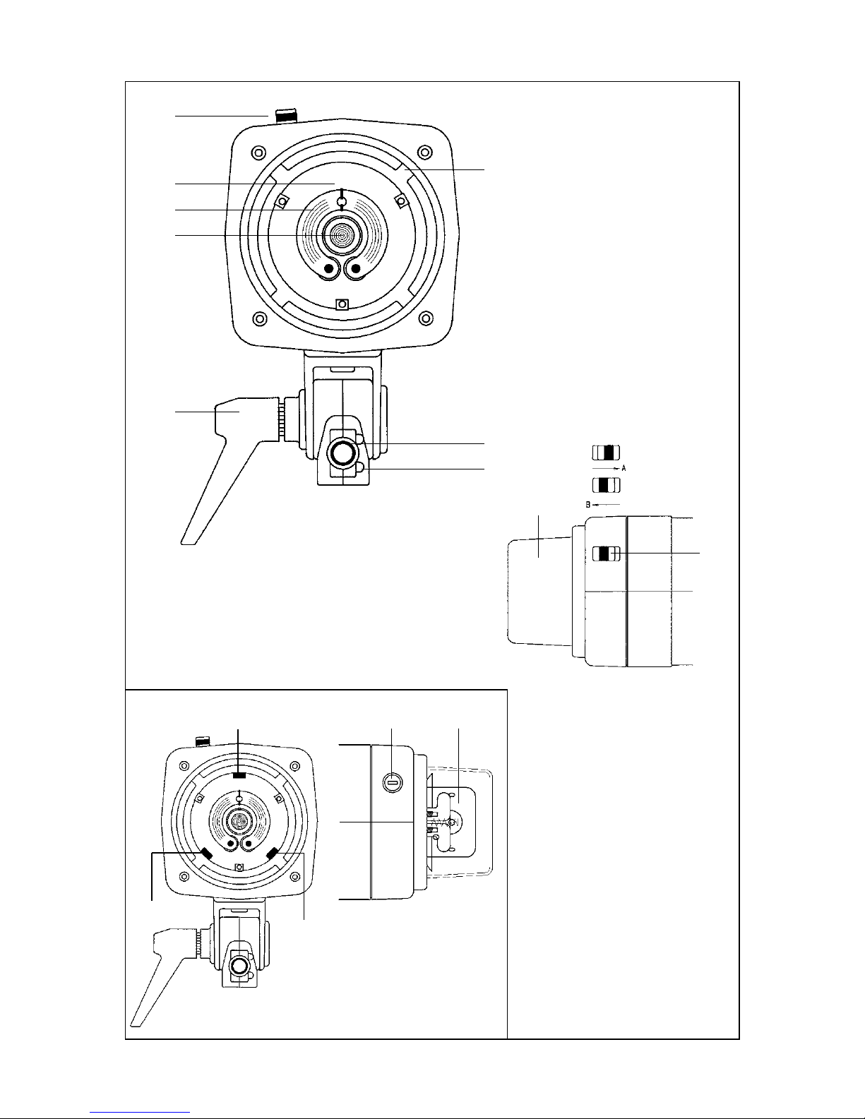
Hebel in Stellung A = Bajonett offen,
Hebel in Stellung B = Bajonett gesperrt.
Hebel (1) in Stellung A bringen, Reflektor in das Bajonett einsetzen und mit Drehung nach rechts zum Einrasten bringen. Lösen in umgekehrter Reihenfolge.
Reflexschirme nur in Verbindung mit dem Schirmreflektor COMSCH, die Halterung für Schirme ist in
diesen Reflektor integriert.
12. Wechseln der Blitz- und Halogenröhre
Gerät ausschalten und vom Netz trennen. Reflektor
oder sonstiges Zubehör vom Gerät abnehmen.
Profilux-Geräte mit 220 - 240 V:
Halogenröhre mit Bajonettfassung. Halogenröhre (20)
leicht nach innen drücken und im gedrückten Zustand
1/4-Umdrehung nach links drehen.
Profilux-Geräte mit 110 - 130 V:
Pyrex-Schutzglas (25) entfernen, siehe Punkt 15.
Halogenröhre nach vorne herausziehen.
Röhre entfernen. Neue Röhre einsetzen, die neue
Halogenröhre dabei nicht mit den Fingern direkt berühren. Herstellerinstruktion in der Verpackung beachten.
Vor dem Wechseln der Blitzröhre das Gerät ausschalten, vom Netz trennen und ca. 1 h warten, bis sich die
Kondensatoren entladen haben. Die Blitzröhre (19) vorsichtig nach vorne herausziehen und durch neue ersetzen. Dabei darauf achten, daß die Blitzröhre bis
zum Anschlag im Sockel sitzt und der
Zündanschluß (21) beidseitig um die Blitzröhre liegt.
13. Sicherungen
Zum Wechseln der Sicherungen Gerät ausschalten und
vom Netz trennen. Sicherungslade (9): Einen kleinen
Schraubendreher hinter dem oberen Teil der
Sicherungslade (9) ansetzen und diese nach vorne
herausdrücken. Die Gerätesicherung befindet sich im
hinteren Teil, die Ersatzsicherung im vorderen Teil der
Sicherungslade. Defekte Sicherung ausschließlich
durch gleichwertige Sicherung ersetzen:
Profilux - 200/400/600 220 - 240 V = T 3,15 A
Profilux - 200/400/600 110 - 130 V = T 4 A
14. Thermische Sicherheit
Die Geräte sind mit einem Thermoschalter gesichert.
Bei einer sehr hohen Umgebungstemperatur und hoher Dauerbelastung der Geräte kann der
Thermoschalter ansprechen.
Spricht dieser Thermoschalter an, ist das Gerät nicht
mehr blitzbereit, und das Halogenlicht erlischt. Die LED
(15) über dem Handauslöser (14) leuchtet NICHT, alle
anderen LED’s leuchten weiter. Nach erfolgter Abkühlung schaltet sich das Gerät automatisch wieder ein.
Die Geräte werden durch einen eingebauten Ventilator im Normalfall ausreichend gekühlt.
15. Schutzglas
Profilux-Geräte 110 - 130 V sind vom Werk aus mit
einem Pyrexschutzglas (25) ausgerüstet. Zum Entfernen die beiden Federdrähte (26) mit einem Stift nach
innen drücken und unter den Schrauben (27) hervorheben. Nach erfolgtem Röhrentausch das Schutzglas
(25) wieder aufsetzen und die beiden Federdrähte (26)
unter die Schrauben drücken.
16. Pflege und Service
Nach Beendigung der Arbeit sollte das Profilux vom
Netz getrennt werden. Bei ständigem Gebrauch sollten die Geräte einmal jährlich in unserem Service überprüft werden.
Das Blitzgerät darf auf keinen Fall Spritz- oder
Tropfwasser ausgesetzt werden.
Bruksanvisning
PROFILUX 200 - 400 - 600
Observera:
Var noga med att formatera kondensatorerna innan
utrustningen används första gången och sedan var
tredje månad om de står oanvända.
Detta göres på följande sätt:
1. Anslut aggregatet till nätet och sätt på det.
2. Ställ in aggregatet på full effekt (1/1).
3. Utlös INTE blixten!!!
4. Låt aggregatet stå så i en timme.
5. Sätt INTE på inställningslampan.
Kondensatorerna är formaterade efter en timme, och
aggregatet kan användas.
1. Grundutrustning
Aggregat med instickbart blixtrör, halogenlampa för
inställningsljus med bajonettfattning sockel B 15 d,
nätkabel, synkkabel,skyddslock och extrasäkringar.
2. Tillbehör
Diverse utbytbara reflektorer, hopfällbara bouncers,
bikakefilter, paraplyer, avskärmningsklaffar, fresnell-
spot, stativ (se sammanställningen på sista sidan).
3. Utförande
Aggregaten har snabbkoppling (11) med stativhylsa
5/8" (16), vilken passar på alla belysningsstativ med
en 5/8" tapp. Stativ som saknar en sådan tapp
behöver en adapter MA-151. Efter att ha lossat vredet
(10) kan aggregatet tiltas upp eller ner genom att
använda handtaget (2). För att låsa aggregatet i läge
vrides vredet (10) medurs.
4. Iordningställande av aggregatet
Sätt i halogenlampan (se punkt 12). Se till att blixtröret
är korrekt isatt. Sätt i nätkabeln i uttaget (8) och anslut
det till nätet. Sätt på aggregatet med den gröna
huvudströmbrytaren (6). Under uppladdningen av
blixten lyser lysdioden (15) svagt. När lysdioden (15)
lyser starkt så är aggregatet färdigt för att användas.
Funktion av lysdiod (15):
Lyser SVAGT: Aggregatet laddas upp
Lyser INTE ALLS: Laddar ur (från högre effekt till
Lyser STARKT: (med korta blink) Aggregatet är
5. Nätanslutning
Aggregaten är fabriksinställda för 220 - 240 V / 50
- 60 Hz eller 110 - 130 V / 50 - 60 HZ växelström.
Kontrollera före anslutning till nätet att volttalet
på typskylten (17) överensstämmer med volttalet
i nätet.
6. Starta inställningsljuset
Efter att ha satt på aggregatet med den gröna
huvudströmbrytaren (6) kan man sätta på in-
ställningsljuset med den gula knappen (7). När
inställningsljuset är påslaget lyser den gröna
(1) Schieber Zubehörarretierung
(2) Handgriff
(3) Fotozelle / IR-Empfänger
(4) Energieregelung
(5) Leuchtdioden
(6) Hauptschalter EIN / AUS
(7) Halogenlicht EIN / AUS
(8) Buchse Netzkabel
(9) Sicherungshalter
(10) Handhebel
(11) Hülse 5/8"
(12) Halogenlicht 100%
(13) Optische / akustische Abblitzkontrolle
(14) Handauslöser
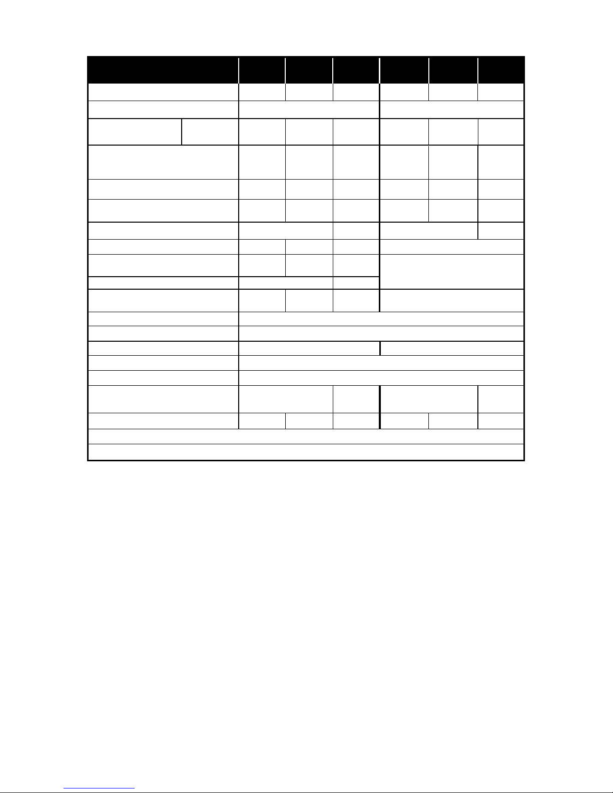
Toleranzen der technischen Daten für Meßwerte und Bauelemente nach DIN und IEC-Norm
Technische Änderungen vorbehalten
Abmessungen 118 x 118
Länge (mm)
Gewicht kg
Blitzenergie ~J(Ws)
Netzspannung V
Variationsbereich
~J(Ws)
stufenlos
Blitzfolge sec
Blitzdauer t 0,5 sec
Blitzröhre, UV-gesperrt Code:
Halogeneinstellicht 100% W
Halogenröhre W/Sockel
OSRAM/Radium serienmäßig Typ
Halogeneinstellicht,
Variationsbereich
W
Blitzauslösung
Synchronkabel-Spannung V
Anschlußwerte A/VA (W)
Blitzspannungsstabilität %
Elektrische Sicherheit
Blende, 1m, ISO 100
Leitzahl, m, ISO 100
Refl.
FILNOS-2/50°
200 400 600 200 400 600
220-240
32,8
42
64,1
67
90,1
94
32,8
42
64,1
67
90,1
94
COMROW - 4 COMROW - 4
75 150 200
75/B15 d
64473 AM/RH75T
150/B15 d
64471AM/RH150TK
200/GX 6,35
Osram 64503
25-20010-75
Fotozelle, Synchronkabel, Handauslöser, Infrarot
9
3,15 / 750
4,0 / 520
+/- 1
Funkentstörung, CE, DIN IEC 491, VDE 0882
295336295
1,7
1,85
2,3 1,75 1,9
2,35
25-200 50-400
75-600
25-200
50-400
75-600
0,5-2,20,4-1,30,3-0,80,8-2,40,5-1,30,4-0,8
1/600-
1/1200
1/4001/700
1/3001/600
1/600-
1/1200
1/4001/700
1/3001/600
110-130
250 / 64479 AM/RH250T
20-150
336
Technische Daten PROFILUX
200
400
600
200
400 600
PROREW
PROREW
250
250/B15 d
64479AM/RH250T
30-250
Halogen maximal W
(15) LED-Bereitschaftsanzeige
(16) Rändelschraube Stativbefestigung
(17) Typenschild
(18) Buchse Synchronkabel
(19) Blitzröhre
(20) Halogenröhre
(21) Zündung Blitzröhre
(22) Schutzkappe
(23) Reflektor-Bajonett
(24) Sicherung F 2 A
(25) Pyrex-Schutzglas
(26) Federdrähte
(27) Positionsschrauben

4 17
Operating Instructions
PROFILUX 200 - 400 - 600
Caution:
Be sure to form the flash capacitors before first use
of the equipment as well as after every three month
of storage.
To do this, proceed as follows:
1. Switch unit on.
2. Set unit for full power (1/1).
3. Do NOT fire any flashes!!!
4. Leave unit in this condition for one hour.
5. Do NOT turn on the modeling light.
The capacitors are formed after one hour, and the
unit may be used.
1. Basic outfit
Flash unit with plug-in flash tube, halogen modeling
tube with B 15 d base, power cable, sync cable,
protective globe and spare fuse.
2. Accessories
Various interchangeable reflectors, folding reflectors,
honeycomb filters, umbrellas, barn doors, snoot,
Fresnel-lens attachment, stands. (See system diagram on back.)
3. Design
The units have a 5/8in. socket (11) with clamp (16),
which fits all lighting stands with a 5/8in. stud. Stands
without such a stud need an MA-151 adapter. After
loosening lever (10), the unit can be tilted up or down
using handle (2). To lock the unit, turn the adjustable
lever (10) clockwise.
4. Preparing for operation
Insert halogen tube, making sure it is properly seated
(see item 12 of these instructions). Plug the power
cable into socket (8) at the bottom of the unit, and
connect it to a wall outlet. Switch unit on with green
master switch (6); the green LED (5) above master
switch (6) lights up. While the flash is charging, the
LED (15) will glow very weakly. Once LED (15) lights
brightly, the unit is ready to fire.
Functions of LED (15):
WEAK glow: Unit is charging
OFF: Discharging (from high to lower
power or after operation of thermal circuit breaker, item 14)
Lights BRIGHTLY, goes out briefly:
Unit ready to fire.
5. Power supply
The units are factory-set for 220 - 240V / 50 - 60Hz
or 110 - 130V / 50 - 60Hz AC. Before connecting
to the power supply, check whether your rated
voltage agrees with the operating voltage
specified on nameplate (17).
6. Switching on the modeling light
After switching the unit on with the green master
switch (6), you may turn on the modeling light using
the yellow switch (7). When the modeling light is on,
the LED above the switch will light green. The
brightness of the modeling light varies in proportion
with the flash output selected.
Profilux units for 220 - 240 V:
Profilux 200 comes with a 75 W halogen tube, Profilux 400 with 150 W and 600 with 250 W halogen
tubes. These tubes are compatible with all Profilux
models. A 250 W halogen tube is available as an
optional accessory. This is also suited for use in
any of the three models. The halogen tubes do not
need any special fuse within the unit and have a
burning life of 2000 hours.
Profilux units for 110 - 130 V:
All units come with a 120 V / 200 W halogen tube with
GX 6.35 base. This tube needs its own F 2 A fuse
housed at the front of the unit (24) as well as a
protective Pyrex globe (25). To change the globe, see
item 15.
7. Output control
Flash output can be continuously varied from approx.
12.5% to 100% (over a range of four f-stops). Flash
and halogen light have a fixed relationship and are
varied proportionally to each other. When you reduce
the power setting, excessive energy is dissipated
within the unit; LED (15) does NOT light during this
period.
8. 100% modeling light
With the aid of switch (12), the modeling light can be
switched from proportional to 100% output,
regardless of the flash output selected with knob (4).
Halogen 100%: LED above switch (12) lights green.
9. Optical and acoustic firing monitor
The units provide optical and acoustic firing control
that can be activated with switch (13).
Switch (13) depressed/LED above switch (13) lit
green: After firing, the modeling light will go out until
the unit is once more ready to fire. When using several
units it is thus easy to check whether all units have
fired.
Switch (13) in opposite position/LED above switch
(13) OFF: An acoustic signal sounds after firing; the
optical monitor is deactivated.
10. Synchronization
Plug the sync cable into terminal (17) in the base of
the unit and connect it to the camera. Slaves can be
fired via the photocell (3). This also doubles as an
infrared sensor.
11. Changing reflectors
All reflectors have a bayonet mount and can be
locked in the bayonet (23) with slide (1).
Slide set to A = Mount open.
Slide set to B = Mount locked.
Move slide (1) to A, insert the reflector in the mount,
and turn clockwise to lock. To remove the reflector,
proceed in the reverse order. Use umbrellas
exclusively with COMSCH umbrella reflector which
includes the umbrella holder.
12. Changing the flash and halogen tubes
Switch unit off and pull the power plug. Remove
reflector and other accessories.
worden.
Handel in stand A = bajonet ontgrendeld
Handel in stand B = bajonet vergrendeld
Handel (1) in stelling A; reflector in de bajonet
plaatsen en met een draai naar rechts fixeren.
Demonteren geschiedt in de omgekeerde volgorde.
De paraplu alleen in combinatie met de
paraplureflector (Comsch) gebruiken. De houder voor
de paraplu is in deze reflector geïntegreerd.
12. Wisselen van halogeenlamp en/of flitsbuis
Flitsapparaat uitschakelen en stekker uit het
stopcontact nemen. Eventueel geplaatste reflector
verwijderen.
Profilux – flitser met 220 - 240 V:
Halogeenlamp met bajonetvatting. Halogeenlamp
(20) licht naar binnen drukken en een kwart slag naar
links draaien.
Profilux – flitser met 110 - 130 V:
Pyrex-beschermglas (25) verwijderen, zie punt 15.
Halogeenlamp naar voren eruit nemen.
Het plaatsen van een nieuwe halogeenlamp
geschiedt in omgekeerde volgorde, daarbij mag de
halogeenlamp niet met de handen aangeraakt
worden (zie aanwijzing in verpakking halogeenlamp).
Voor het wisselen van de flitsbuis dient de flitser
minimaal een uur niet op het stopcontact aangesloten
te zijn, dit in verband met restspanning in de
condensatoren.
De flitsbuis (19) voorzichtig naar voren uit de flitser
trekken.
Het plaatsen gebeurt in omgekeerde volgorde, en
tot de aanslag in de flitser plaatsen. LET OP: de
flitsbuis moet tevens tussen de ontsteek
electroden (21) klemmen.
13. Zekeringen
Voor het verwisselen van de zekeringen de flitser
uitschakelen en de stekker uit het stopcontact halen.
Zekeringhouder (9): een kleine schroevendraaier

Profilux units for 220 - 240 V:
Halogen tube with bayonet mount. Lightly press tube
(20) inwards and, keeping it depressed, turn through
º revolution counterclockwise.
Profilux units for 110 - 130 V:
Remove Pyrex globe (25); see item 15. Withdraw
halogen tube.
Remove tube and replace with new one, taking care
not to touch the new tube with your fingers. Follow
manufacturer’s instructions.
Before changing the flash tube, switch the unit off,
pull the power plug and wait for about one hour to
allow the capacitors to discharge. Then carefully
withdraw flash tube (19) and replace it with a new one.
Make sure that the tube is firmly seated all the way
down in the base, the triggering contact (21)
surrounding the tube on either side.
13. Fuses
To change fuses, switch the unit off and pull the
power plug. Fuse drawer (9): Push the fuse drawer
(9) out towards the front with the aid of small
screwdriver placed behind the upper part of the
drawer. The fuse is located at the rear, a spare fuse
at the front of the drawer. Always replace the blown
fuse by one of identical rating:
Profilux - 200/400/600 220 - 240 V = T 3.15 A
Profilux - 200/400/600 110 - 130 V = T 4 A
14. Thermal protection
The units have a thermal circuit breaker that responds
to very high ambient temperature and heavy-duty
use.
When the circuit breaker acts, the flash will not fire
any more, and the modeling light goes out. The LED
(15) above the open-flash button (14) is OFF, while all
other LEDs stay lit. Once it has cooled down
sufficiently, the unit switches on automatically. Under
normal operating conditions, the built-in fan provides
sufficient cooling.
15. Pyrex globe
Profilux units for 110 - 130 V are factory-equipped
with a protective Pyrex globe (25). To remove the
globe, press the two wire springs (26) inwards with a
pointed object so that they clear the screws (27), and
lift them out. After changing the flash tube, replace
the globe (25) and press the two springs (26) back
underneath the screws.
16. Care and maintenance
At the end of the shoot, pull the power plug. Units that
are used regularly should be serviced by Multiblitz
once a year.
The flash unit should be carefully protected from
water splashes.
 Loading...