

Operations Manual

!
!
!
!
2!
Content
Introduction 3
General safety instructions 4
M6-TTL 6
- Operating panel 6
- Unit 7
- Power connection and mechanical main switch 7
Initial start-up 8
Operation modes 11
- TTL (ETTL, I-TTL) mode 11
- Manual (M) mode 15
- Sequence mode (SEQ) with PC cable 19
- FP mode/ High-Speed-Synchronisation 20
Miscellaneous 24
- Removing / changing the battery 24
- Battery status 24
- Replacement of flash tube and LED modeling light 24
- Mains operation 24
- TTL/FP modes with TTL-TRIGGER C & N remote controls 25
- Firmware update 25
- M6-TTL accessories 27
- Specifications 28
- Warranty 29

!
!
!
!
3!
Our name stands for technical
revolution
Thank you for choosing MULTIBLITZ, we hope you enjoy working with
this premium quality product.
Physicist Dr. Ing. Dieter Mannesmann, who founded Multiblitz
in 1948, is considered one of the pioneers of studio flash
technology. Through the development of the first electronic
flash units under the name „Multiblitz“ he revolutionized
professional photography. With the help of this new light
source, it was possible for photographers to trigger multiple
flashes without changing the flash bulb after each image. This
groundbreaking invention was followed by many more ideas and
innovations. Among other things, Dr. Ing. Mannesmann derived
today’s common definition of the Guide Number, which is used
by photographers throughout the world. To date, we are
continuing the legacy of Dieter Mannesmann with new
groundbreaking concepts and reliable premium lighting
solutions.
We are one of the most innovative studio lighting equipment
manufacturers in the world, and have been for over 65 years.
Our goal is to set new standards and to achieve the best
outcome for all those for whom light shaping is a key part of
their profession and art.

!
!
!
!
4!
CAUTION!
General safety instructions
Please read the instruction manual carefully before using this
product!
Flash-/ and halogen tubes as well as metal parts can become
very warm during operation and may cause burns if not handled
properly.
Opening the unit could be extremely dangerous! Do not open
the unit by yourself! Service should only be executed by an
authorized MULTIBLITZ service location.
Do not obstruct the venting slots.
Do not place filters, diffusing materials, or any other
obstructions directly onto the ash-/ and halogen tubes.
Do not expose the unit to water, nor spray-/or dripping water.
Solely use the supplied Multiblitz lithium-ion battery (art. no.
719665) for battery operation. For mains operation solely use
the corresponding multi-voltage power supply (art. no.
719668), available separately.
The crossed out wheeled bin label that can be
found on your product indicates that this product
should not be disposed of via the normal household
waste stream. To prevent possible harm to the
environment or human health please separate
this product from other waste streams to ensure that it can be
recycled in an environmentally sound manner.
For more details on available collection facilities please contact
your local government office or the retailer where you
purchased this product.

!
!
!
!
5!
WEEE registration no.: DE 64253330
In order to avoid excessive concentration of ozone produced by
using strong flash units, it is necessary to ventilate confined
spaces regularly.
The minimum distance of 0.3m to the illuminated area must
be strictly maintained.
This unit should be serviced once a year by an authorized
MULTIBLITZ service location.
!
!
!
!
6!
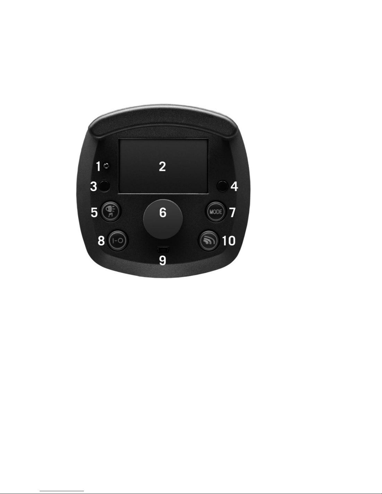
M6-TTL
Operating panel
1. Photocell
2. LCD display
3. Selector button (groups, power)
4. Selector button (channel/ID, repetitions/frequency)
5. Selector button (modeling light ON-OFF, acoustic
charging check ON-OFF)
6. Control button (power flash energy/LED modeling light,
select channel/ID, select repetitions/frequency,
display/key illumination ON)
7. Sequence mode ON-OFF
8. Unit ON-OFF, TEST
9. USB interface
10. Selector button (manual mode with synchronisation via
photocell/cable, TTL mode)
!
!
!
!
7!
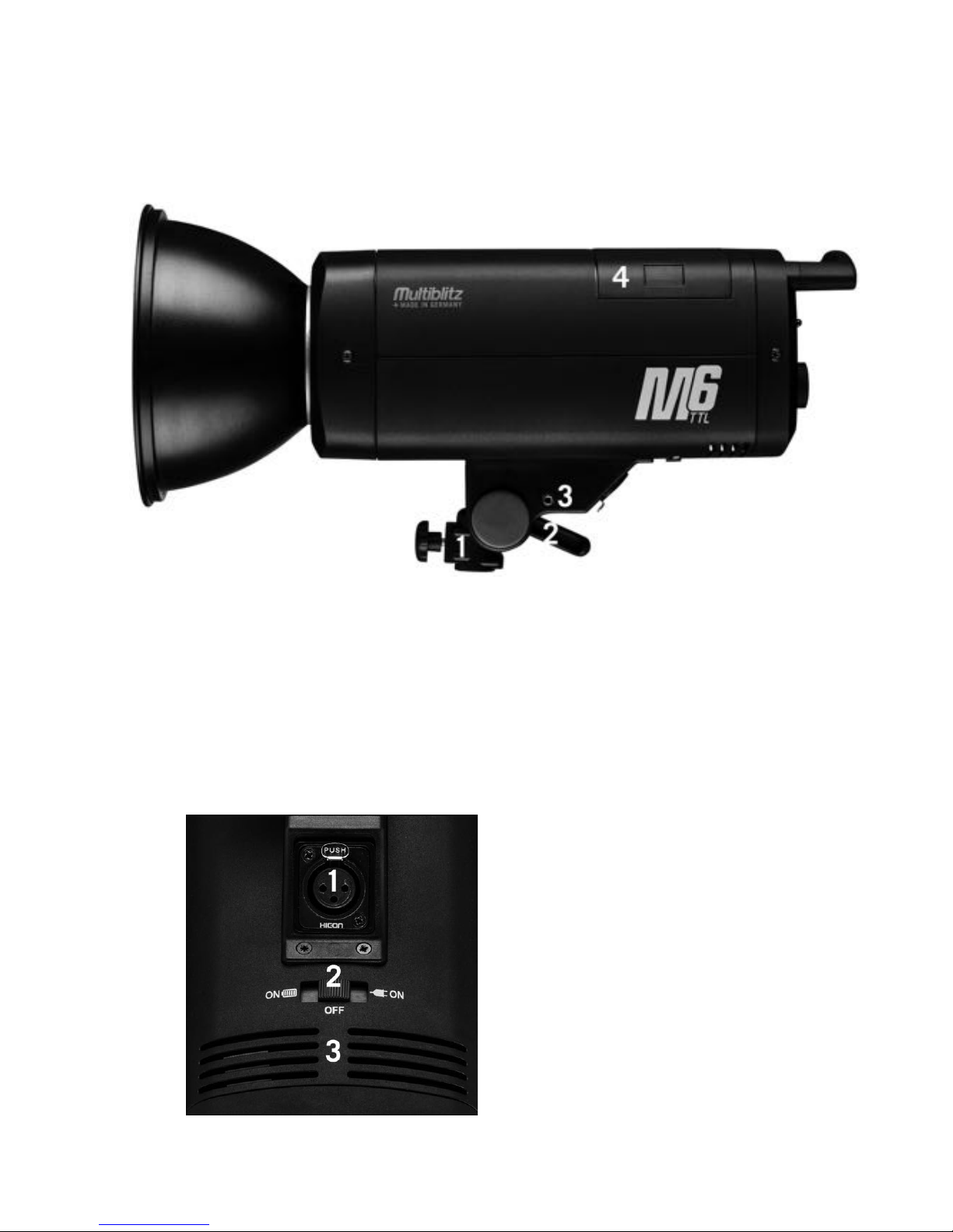
Unit
1. Stand adapter with fixing screw
2. Inclinations fixing lever
3. Sync socket
4. Battery compartment with battery
Power connection and mechanical main
switch
A multi-voltage adapter (art.
no. 719668), available
separately, can be attached
to the power connection
socket 1., on the underside
of the M6-TTL. This allows
the unit also to be operated
in 110V-260V networks.
Using the mechanical main
switch 2., you can switch the
!
!
!
!
8!
unit to battery or mains operation as required. In the OFF
status, the battery in the unit is separated from the electronics
and the unit cannot be switched on using the "I-0" button on
the operating panel. This status is recommended for
transporting the M6-TTL.
Adapter connection (adapter available separately) Mechanical
main switch (battery mode ON / unit OFF / Mains mode ON)
Ventilation openings.
Initial start-up
Remove the protective cap from the unit by pushing the red
reflector lock on the underside of the unit towards the
operating panel, then turn the protective cap anti-clockwise
and remove it. You can now connect a light shaper of your
choice to the unit by inserting the bayonet ring into the bayonet
mount of the unit, turning it clockwise and closing the reflector
lock again by pushing it towards the connected light shaper.
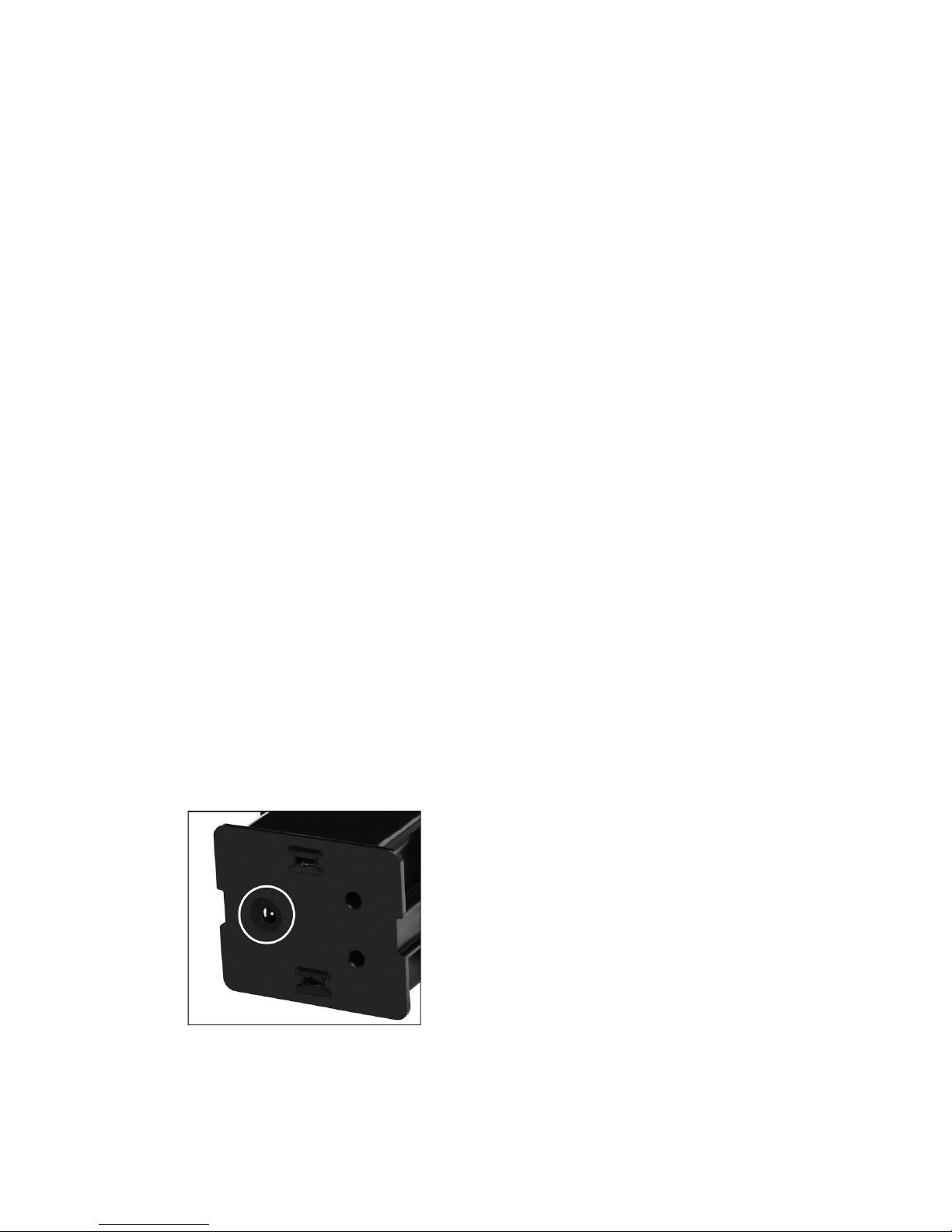
To ensure optimum performance, the battery must be charged
before using the unit for the first time. To charge the battery,
you must only use the Multiblitz Li-Ion charger supplied (art.
No. 719666).
Connect the battery charger to the corresponding socket on the
underside of the M6-TTL battery.
Fig.: Battery charging socket
!
!
!
!
9!
Check the charging display on the charger.
If the battery charger indicates the charging process has
finished and the charging status display on the charger is
flashing green, the battery can be disconnected from the
charger.
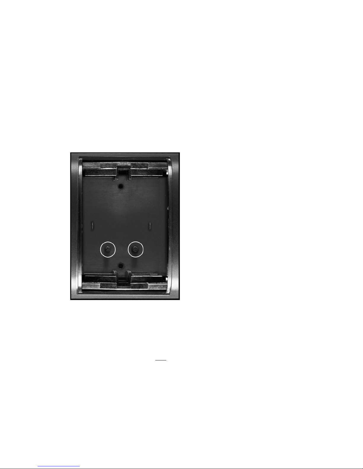
Insert the battery supplied into the corresponding battery
compartment on the upper side of the unit, press gently on the
battery from the top until it audibly clicks into the unit.
Important note: The type
label of the battery should
point towards the operating
panel when it is being
inserted.
The anti-twist safeguard in
the battery compartment (see
markings, Fig. on left)
prevents the battery from
being inserted with the wrong
polarity.
Fig.: Battery compartment with
safety unit
Using the mechanical main switch on the underside, switch the
unit to the required operating mode (battery or mains mode,
ON).
Important note: The battery can remain in the unit during
mains mode but is then not automatically charged.
Switch on the unit using the "I-0" button on the operating
panel, holding the button down for about a second (you will

!
!
!
!
10!
switch the unit off again if you hold down the same button for
three seconds).

!
!
!
!
11!
Operating modes
TTL (Thru the lens) Mode
In TTL Mode, the M6-TTL automatically adjusted to the flash
measurement mode of the camera. In coordination with the
camera's flash control, the M6-TTL automatically sets the flash
power. If required, a lighting correction can be carried out,
which can be set in levels of a third up to ±3 levels.
Important note: TTL Mode on the M6-TTL can only be used
with a separately available Multiblitz TTL Trigger remote
control C or N which is used for communication between the
camera and the flash unit and takes over the TTL control on
the M6-TTL.
Button functions in TTL Mode

!
!
!
!
12!
1. Selector button (group A, B, C)
2. Selector button (Channel/ID)
3. Selector button (modeling light ON-OFF, acoustic
charging check ON-OFF)
4. Control button (power modeling light, 10-100% /
channel & ID)
5. Unit ON-OFF, TEST
6. Selector button (manual mode with synchronisation via
photocell/cable, TTL Mode)
Group select
With the selector button 1. select the required flash group (A,
B, C) the unit is to be assigned to.
Channel/ID select
With the selector button 2., select the channel and the ID to
which the unit is to be assigned to. Operating the button 2.
marks the channel number "CH" in the display, and the control
button 4. can now be used to select the required channel (1-
15). Operating the selector button 2 again marks the ID
number "ID" in the display, and the control button 4. can be
used now to select the required ID (1-99). Turn to the right to
select the units (.1-.9), or to the left for the tens of the
required ID. Use selector button 2. again to leave Select.
Important note: All units within a flash set-up must be set to
the same channel (CH) so that the units flash synchronously,
as required, when triggered.
By selecting the ID, you are giving each unit in your flash setup a "name" (ID no.) so that every unit can be controlled
individually (power, charging check, etc.).
The same settings for channel (CH) and ID should therefore be
set on the separately available Multiblitz TTL Trigger remote
control C or N.

!
!
!
!
13!
Activating the modeling light and the acoustic charging check
Briefly operate button 3. to switch on the modeling light ONOFF. If you operate button 3. for longer, you will switch the
acoustic charging check ON-OFF.
Adjusting the modeling light
If the modeling light is activated (see above), the desired power
can be set via control button 4..
Triggering a TEST flash
Operate button 5. to trigger a TEST flash.
Switching between synchronisation modes
Operate button 6. to switch between
• TTL Mode
• Manual mode, synchronisation via photocell
• Manual mode, synchronisation via synchronising cable
All further functions for use of TTL Mode are switched on via
the separately available Multiblitz TTL trigger remote control C
or N.
Please see the relevant instructions for more information.
Note for Nikon cameras: If the "FP" function is activated in the
camera menu, high-speed synchronisation is also
automatically active in TTL Mode and all the camera's
specified shutter speeds can be used.
Note for Canon cameras: With Canon cameras, switching must
be carried out manually on the Multiblitz TTL trigger remote
control C. You will find further information on this in the
operating instructions for your Canon camera and in the

!
!
!
!
14!
operating instructions of the Multiblitz TTL trigger remote
control C.

!
!
!
!
15!
M (Manual) Mode
In manual mode, the M6-TTL can be used like a classic flash
unit, e.g. for studio operation. The power is regulated with the
power control button via eight apertures in 1/3 aperture stops
(1/128 - 1/1). The M6-TTL can be triggered / synchronised
with a camera in manual mode via the supplied synchronising
cable, visually via the photocell and remotely via the built-in
radio receiver.
Important note: For triggering/synchronisation via remote, the
separately available Multiblitz TTL trigger remote control C or N
is required.
Button functions in manual mode "M" for
synchronisation via photocell, symbol in display
"Eye"

!
!
!
!
16!
1. Selector button (power control modeling light/flash
energy)
2. Selector button (modeling light ON-OFF, acoustic
charging check ON-OFF)
3. Power control button (modeling light 10-100%, flash
energy 1/128-1/1)
4. Unit ON-OFF, TEST
5. Selector button (manual mode with synchronisation via
photocell/cable, TTL mode)
Adjusting the modeling light and flash energy
Using the selector button 1., choose whether you wish to use
the power control button 3. to adjust the power of the modeling
light or the flash energy. By pressing button 1., the flash power
display is marked in the display and can be set using the power
control button. Press button 1. again to adjust the power of the
modeling light. (After seven seconds, the marking of the flash
power display goes off automatically and the modeling light can
be adjusted again).
Activating the modeling light and the acoustic charging check
Briefly operate button 2. to switch the modeling light ON-OFF.
By operating button 2. for longer, you switch the acoustic
charging check ON-OFF.
Triggering a TEST flash
Operate button 4. to trigger a TEST flash.
Switching between synchronisation modes
Operate button 5. to switch between
• Manual mode, synchronisation via synchronising cable
• TTL mode
• Manual mode, synchronisation via photocell

!
!
!
!
17!
Button functions in manual mode "M" for
synchronisation via synchronising cable, symbol in
display "SL"
1. Selector button (power control modeling light/flash
energy)
2. Selector button (repetitions/frequency in sequence
mode "SEQ")
3. Selector button (modeling light ON-OFF, acoustic
charging check ON-OFF)
4. Control button (modeling light 10-100%, flash energy
1/128-1/1, select repetitions/frequency in sequence
mode "SEQ")
5. Selector button (Sequence mode "SEQ" ON-OFF)
6. Unit ON-OFF, TEST
7. Selector button (manual mode with synchronisation via
photocell/cable, TTL mode)

!
!
!
!
18!
Adjusting the modeling light and flash energy
Using the selector button 1., choose whether you wish to use
the power control button 3. to adjust the power of the modeling
light or the flash energy. By pressing button 1., the flash power
display is marked in the display and can be set using the power
control button. Press button 1. again to adjust the power of the
modeling light. (After seven seconds, the marking of the flash
power display goes off automatically and the modeling light can
be adjusted again).
Activating the modeling light and the acoustic charging check
Briefly operate button 2. to switch the modeling light ON-OFF.
By operating button 2. for longer, you switch the acoustic
charging check ON-OFF.
Triggering a TEST flash
Operate button 4. to trigger a TEST flash.
Switching between synchronisation modes
Operate button 5. to switch between
• TTL Mode
• Manual mode, synchronisation via synchronising cable
• Manual mode, synchronisation via photocell

!
!
!
!
19!
Sequence mode (SEQ) with synchronising cable
If synchronisation via synchronising cable is selected, it is
possible to switch within manual mode to SEQ (sequence)
mode in order, for example, to flash several times during a time
exposure in order to show the movements of an athlete or
similar as a motion sequence on a photo*.
Activating sequence mode
Operate button 5. to activate sequence mode.
Setting parameters (Ti/Hz)
Using button 2., select, by operating once, the required
number of flashes; the selected parameter will be marked in
the display. The required number of flashes can now be set
with control button 4.
By operating button 2. a second time, select the number of
flashes per second (Hz); the selected parameter will be marked
in the display. The required frequency can now be set with
control button 4..
Confirm the selected parameters by operating the button a
third time.

!
!
!
!
20!
Important note: To be able to use the sequence mode of the
M6-TTL properly, it is recommended that the shutter speed of
the camera is set a time exposure ("Bulb" mode).
FP (Focal Plane) Mode / High-Speed
Synchronisation
For high-speed synchronisation, you can use the M6-TTL in
"FP" at all shutter speeds which are specified by the camera
being used*. In addition, flash durations defined at the M6TTL of 1/8000, 1/11000, 1/13000, 1/14000 sec** can be set
for high-speed synchronisation.
Important note: The unit can only be switched to FP mode in
combination with a separately available Multiblitz TTL trigger
remote control C or N.
Accordingly, FP Mode can only be used on the M6-TTL in
combination with a Multiblitz TTL trigger remote control C or N
which communicated between the camera and the flash unit
and takes over FP control at the M6-TTL.
Note for Nikon cameras: If the "FP" function is activated in the
camera menu, high-speed synchronisation is also automatically
active in TTL mode and all the specified shutter speeds of the
camera can be used.
Note for Canon cameras: With Canon cameras, switching must
be carried out manually at the Multiblitz TTL trigger remote
control C. You will find further information about this in the
operating instructions of your Canon camera and in the
operating instructions of the Multiblitz TTL trigger remote
control C.

!
!
!
!
21!
Button functions in FP mode
1. Selector button (group A, B, C)
2. Selector button (channel/ID)
3. Selector button (modeling light ON-OFF, acoustic
charging check ON-OFF)
4. Control button (power modeling light, 10-100% /
channel & ID)
5. Unit ON-OFF, TEST
6. Selector button (FP OFF, manual mode with
synchronisation via photocell/cable, TTL mode)
Group select
With the selector button 1., select the required flash group (A,
B, C) which the unit is to be assigned to.

!
!
!
!
22!
Channel/ID select
With the selector button 2., select the channel and the ID to
which the unit is to be assigned to. Operating the button 2.
marks the channel number "CH" in the display, and the control
button 4. can now be used to select the required channel (1-
15). Operating the selector button 2 again marks the ID
number "ID" in the display, and the control button 4. can be
used now to select the required ID (1-99). Turn to the right to
select the units (.1-.9), or to the left for the tens of the
required ID. Use selector button 2. again to leave Select.
Important note: All units within a flash set-up must be set to
the same channel (CH) so that the units flash synchronously,
as required, when triggered.
By selecting the ID, you are giving each unit in your flash setup a "name" (ID no.) so that every unit can be controlled
individually (power, charging check, etc.).
The same settings for channel (CH) and ID should therefore be
set on the separately available Multiblitz TTL Trigger remote
control C or N.
Activating the modeling light and the acoustic charging check
Briefly operate button 3. to switch on the modeling light ONOFF. If you operate button 3. for longer, you will switch the
acoustic charging check ON-OFF.
Adjusting the modeling light
If the modeling light is activated (see above), the desired power
can be set via control button 4.
Triggering a TEST flash
Operate button 5. to trigger a TEST flash.

!
!
!
!
23!
Switching between synchronisation modes
Operate button 6. to switch between
• FP Modus
• Manual mode, synchronisation via photocell
• Manual mode, synchronisation via synchronising cable
• TTL Mode
All further functions for use of TTL Mode are switched on via
the separately available Multiblitz TTL trigger remote control C
or N.
* You will find information about this in your camera's
operating instructions.
** The shorter the flash duration chosen, the lower the flash
power.
Note for Nikon cameras: If the "FP" function is activated in the
camera menu, high-speed synchronisation is also
automatically active in TTL Mode and all the camera's
specified shutter speeds can be used.
Note for Canon cameras: With Canon cameras, switching must
be carried out manually on the Multiblitz TTL trigger remote
control C. You will find further information on this in the
operating instructions for your Canon camera and in the
operating instructions of the Multiblitz TTL trigger remote
control C.

!
!
!
!
24!
Miscellaneous
Removing / changing the battery
Hold down the two locking buttons on the sides of the battery
and pull the battery out of the battery compartment. Replace
the recharged or replacement battery in the battery
compartment as described in Initial start-up, point 2, page ....
Battery status
The battery charging status is shown on the top left in the
display of the M6-TTL,
with three bars inside a battery symbol. If the charge level of
the battery falls too much, the unit switches off automatically
in order to save the battery.
Replacement of flash tube and LED
modeling light
The flash tube (art. no.: 635111) can be replaced by the user
himself.
To replace the LED modeling light, please contact our
Technical Support, your retailer or distributor.
Mains operation
Using a Multi-Voltage Adapter (art. No. 719668), available
separately, the M6-TTL can also be operated in 110V-260V
power networks. Here, the battery can be left in the unit, but is
not charged automatically during mains operation. The output
of the M6-TTL may vary depending on the voltage available.

!
!
!
!
25!
TTL/FP modes combined with TTL TRIGGER
C and N remote controls
In TTL and FP mode, the M6-TTL automatically recognises the
type or remote control or camera (Canon or Nikon) with which it
is communicating. The display then shows ETTL for Canon and
I-TTL for Nikon accordingly.
The TTL remote controls are available separately:
• TTL trigger C, for Canon (art. No. 719667)
• TTL trigger N, for Nikon (art. No. 719670)
Firmware Update
1. Using the USB cable supplied, the latest firmware can
be transferred to the M6-TTL.
2. Using the link www.multiblitz.de/downloads (tab: "M6-
TTL Firmware”) load the firmware onto your computer.
Click on the icon "M6-TTL Version ...”, and the
download starts automatically.
3. Using the USB cable supplied, connect the M6-TTL to
your computer (MAC/PC).
4. The M6-TTL is shown as a drive on your desktop.
5. The following appears on the screen:

!
!
!
!
26!
6. Select "YES”. The download icon appears on the
display.
7. Now drag the downloaded file onto the drive that is
displayed on your desktop.
8. The update starts automatically, progress is shown
in %.
9. As soon as the update is completed, the following
appears on the display:
10. Follow the instruction "Remove” on the display and
remove the USB cable from the unit.
11. The M6-TTL restarts automatically.
12. The firmware update is completed.

!
!
!
!
27!
M6-TTL Accessories
• TTL-Trigger for Canon cameras, art. no. 719667
• TTL-Trigger for Nikon cameras, art. no. 719670
• Multi-Voltage power supply, art. no. 719668
• 12V car charger, art. no. 719673
• V- to P- bayonet mount adapter, art. no. 635114
• Li-Io battery, art. no. 719665
• Multi-Voltage charger, art. no. 719666
• Handle with 5/8" adapter, art. no. 718253
• Padded soft case with shoulder strap, art. no. 719671
Specifications
FLASH POWER
J(WS)
600
GUIDE NUMBER, ISO 100
REFLECTOR FILNOS-
2/65°
93
F-STOP, 2M, ISO 100*
REFLECTOR FILNOS-
2/65°
45,1
POWER RANGE
F-STOP / J(WS)
8 / 4,68 - 600
POWER INCREMENTS
F-STOPS
1/3 & 1/1
LED MODELING-LIGHT
W
10 (EQUALS 50W HALOGEN)
MODELING-LIGHT MODES
OFF, FREE (5-100%)
FLASH MODES
E-TTL, I-TTL, FP, HS, MANUAL, SEQUENCE
SYNC/TRIGGER
SYNC LEAD, RADIO (2.4GHz), CELL (IR)
RECYCLING TIME
SEC
0,1 - 3,5
FLASH DURATION T 0,5
SEC
1/8100-1/650

!
!
!
!
28!
FLASH DURATION T 0,5 IN
FP/HS MODE UP TO...
SEC
1/15000
FLASH DURATION T 0,5
FP/HS 2
SEC
1/14000
FLASH DURATION T 0,5
FP/HS 3
SEC
1/13000
FLASH DURATION T 0,5
FP/HS 4
SEC
1/11000
FLASH DURATION T 0,5
FP/HS 5
SEC
1/8000
COLOUR TEMPERATURE (@
MAX OUTPUT)
K
5500 +/- 150
BATTERY
TYPE
CHANGEABLE LITHIUM-ION / 1,1V-6000mAh-66,6Wh
BATTERY CAPACITY
MAX FLASHES @ MAX
OUTPUT
400
BATTERY CHARGING TIME
HRS, WHEN FULLY
DISCHARGED
3,5
MAINS OPERATION
YES, WITH OPT. MULTI-VOLTAGE POWER SUPPLY, 100 -
240V / 12 V
BUILT-IN WIRELESS
RECEIVER
YES
ACOUSTICAL “READY”
INDICATION
YES
IR/PHOTO CELL ON-OFF YES
“TEST” BUTTON
YES
AUTOMATED COOLING FAN YES
AUTO-DUMPING
YES
COLOUR TEMPERATURE
STABILIZED
YES
FLASH TUBE, UV–
ABSORBING
MROR/MROW
SYNC VOLTAGE
V
< 5
FLASH VOLTAGE STABILITY % +/-0,5
RADIO INTERFERENCE
SUPPRESSION
ACCORDING TO CE, DIN
DIMENSIONS (W x H x L)
MM
120x185x280
WEIGHT WITH BATTERY
KG
2,9
Tolerances of the technical data for measured values and components according to the standard DIN IEC //
Specifications subject to change without notice.
*Metered with 65º FILNOS-2 standard reflector at ISO 100. Distance: 2 m to minimize measuring inaccuracies.
Reflector not included with single unit!

!
!
!
!
29!
3-year limited warranty
Multiblitz warrants products bearing the Multiblitz mark against
defects in materials and manufacture for three years from the
date of purchase by a Multiblitz distributor/the original enduser. If a defect occurs and a valid claim is made under the
warranty within the warranty period, Multiblitz will choose to
either repair the defect using new or reconditioned parts at no
cost, replace the product with a new product or one produced
using new or reconditioned parts, and resulting in at least the
same performance level as the original.
Learn more about our warranty, go to: www.multiblitz.com

!
!
!
!
30!
Multiblitz Mannesmann GmbH – Ferdinand-Porsche-Str. 19 – 51149 Cologne,
Germany
Tel: 02203/9396-35 - www.multiblitz.com - info@multiblitz.com
 Loading...