

Page 1

Thank you very much for selecting our model MCD-008 pocket
digital multimeter.
This model is complex instrument and employ a very reliable
mechanical/electronic design.
Before you use your new instrument, read this Instruction
Manual completely and familiarize yourself thoroughly with
all functions. With proper use and care, your tester will give
you years of satisfactory service.
MULTI MEASURING INSTRUMENTS CO.,LTD.
Akihabara Murai Bldg. 7F, 1-26 Kanda Sakuma-cho,
Chiyoda-ku, Tokyo, 101-0025 Japan
TEL : +81-3-3251-7016 FAX : +81-3-3253-4278
Home Page : http://www.multimic.com/
E-mail : [email protected]
SAFETY SUMMARY observe by all means
The Cautions and Warnings which appear on the following must be followed to ensure
operator safety and retain the operating condition of the multimeter.
△! WARNING : This symbol indicates the contents "Possibilities of the death or
the serious wound can be supposed" caused from mis-operations.
△! CAUTION : This symbol indicates the contents "Possibilities of the injury or
only the material damage can be supposed" caused from mis-
operations.
● The CAUTIONs and WARNINGs which appear on the following pages are stared
to prevent the operator & other people from the dangers and their properties from
the damages beforehand.
△! WARNING
POCKET DIGITAL MULTIMETER
MODEL MCD-008
INSTRUCTION MANUAL
POSSIBLE ELECTRICAL SHOCK
● This instrument is for the use of low voltage circuit.
● Do not make measurements of power lines carrying more than AC 250V.
(In some cases, power lines may carry voltage spikes of several times of the normal
supply voltage).
● Do not make measurements, leaving battery cover removed.
● Before attempting to replace the batteries, first disconnect the test leads from any
energized circuit.
● Do not handle the instrument with wet hands.
It is very dangerous, when measuring voltage is high.
POSSIBLE DAMAGE OF INSTRUMENT
● When making resistance measurement, continuity test or diode test, do not apply
any voltage to the test probes. It will cause the defect.
● Confirm the position of rotary switch before measurement.
● Keep storage this instrument in cool and clean place.
● For cleaning of this instrument, do not apply chemicals such as thinner, benzine, etc.
Page 2
GENERAL SPECIFICATIONS
Measuring Method : Dual integration method
Measuring Function : DC Voltage, AC Voltage, Resistance, Continuity Check,
Diode Test with Data Hold & Auto Power Off functions.
Display : LCD, max. reading of 3200 with bar graph
Polarity : Automatic (-) negative indication
Over Range Indication : "OL" mark on LCD readout
Low Battery Indication : "B" mark is displayed when the battery voltage drops
below operating voltage
Sampling : 2 times/second
Operating Temperature : 0~40℃, <80%RH (non-condensing)
Storage Temperature : -20~60℃, <70%RH (non-condensing)
Power Supply : LR-44 x 2
Power Consumption : Approx. 5mW
Size & Weight : 72(H)x114(W)x22.5(D)mm, approx. 110g
Accessories : Instruction Manual ………… 1, Battery …………2
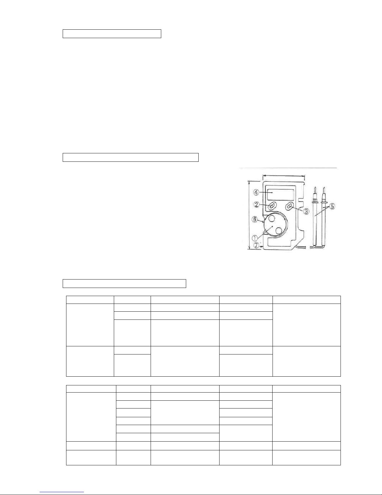
NAME & EXPLANATION OF EACH PART
① ROTARY SWITCH : Power On/Off, Measuring Ranges
for DCV, ACV, Resistance, Diode Test 72
and Continuity Check.
② FUNCTION KEY : When the position of rotary switch is
at Ω. ・))) ➔+, can change from
Ω./ ・))) / ➔+ by turns.
③ DATA HOLD KEY : By pressing this key, the display 114
value will be hold (DH sign will appear)
and it will be released by pressing once
again. (DH sign will disappear).
④ DISPLAY : LCD display for measuring value,
annunciator, battery sign, etc.
⑤ TEST LEADS : Red is for ○+ polarity and Black is for ○-.
⑥ LEVER SWITCH : One touch lever switch for rolling up the test lead wires into the case.
⑦ BATTERY COMPARTMENT (Rear Side)
MEASURING RANGES & ACCURACY
(23℃±5℃,<80%RH non-condensing)
Function
Range
Accuracy
Input Impedance
Max. Input Voltage
DCV
320.0mV
±(1.3%rdg±3dgt)
>1000MΩ
AC/DC 500Vrms
3.200V
±(0.7%rdg±3dgt)
approx. 11MΩ
32.00V
320.0V
500V
±(1.3%rdg±3dgt)
approx. 10MΩ
ACV
(50/60Hz)
3.200V
±(2.3%rdg±6dgt)
approx. 11MΩ
AC/DC 500Vrms
32.00V
320.0V
500V
approx. 10MΩ
Function
Range
Accuracy
Testing Current
Max. Input Protection
OHM
320.0Ω
±(2%rdg±5dgt)
<0.7mA
500Vrms
3.200kΩ
±(2%rdg±3dgt)
<0.13mA
32.00kΩ
<13μA
320.0kΩ
<1.3μA
3.200MΩ
±(6%rdg±4dgt)
<0.13μA
32.00MΩ
±(10%rdg±10dgt)
Diode Test
3.200V
±(10%rdg±3dgt)
approx.. 0.7mA
500Vrms
Continuity
Check
320.0Ω
Continuity Beeper,
<approx. 20Ω
approx.. 0.7mA
500Vrms
Page 3
MEASURING METHOD
1. DC VOLTAGE (DCV)
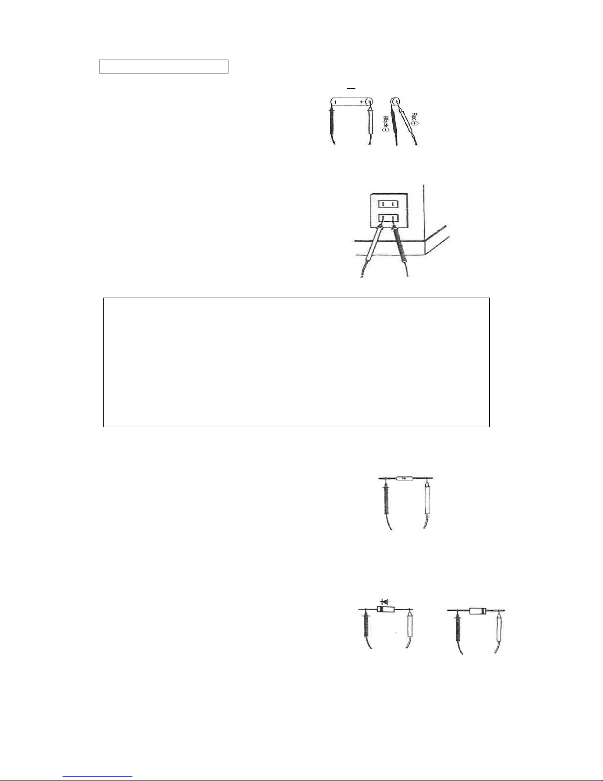
1) Set the position of rotary switch from OFF to DCV (… sign will be displayed).
2) According to the drawings,
red test lead contact to ○
+
polarity
battery etc. and black one to○-.
3) Read the voltage value on the display. (Can measure up to 500V automatically).
2. AC VOLTAGE (ACV)
1) Set the rotary switch position to V and press once the select key to chose「~」.
2) According to the drawings, insert
the test leads to the outlet , etc. to
be measured. (In case of ACV measurement,
red or black test lead and polarity of ○+ or
○- are no concern).
3) Read the voltage value on the display.
(Can measure up to 500V automatically).
△! WARNING
1. Do not apply the input signal more than max. rated input voltage (500V).
2. During measurement, do not change rotary switch position.
3. Do not hold and or touch the nearer position of test leads to the tip over collar
during measurement.
4. POSSIBLE ELECTRIC SHOCK
Confirm that there is no damage in the isolated wire of test leads before
connecting. In case of out of order, stop the operation and repair them.
5. POSSIBLE DAMAGE & FIRE HAZARD
Connect test leads firmly, the wrong connection may cause spark.
3. RESISTANCE (Ω)
1) Set the rotary switch position to Ω. ・))) ➔+ and chose Ω by select key.
2) According to the drawing, contact test leads
to the both sides of the resister to be measured.
(It does not matter about ○+○- polarity).
3) Read the resistance value on the display.
(Can measure up to 40MΩ automatically).
4. DIODE TEST ( ➔+ )
1) Set the rotary switch position toΩ. ・))) ➔+ and chose ➔+ by select switch.
2) In case of measurement for the forward voltage,
contact the test leads as in the way of drawing. Forward Voltage Backward
Voltage
The measuring range of general diode is between ➔+
0.4 and 0.7V.
3) In case of the backward voltage, contact the test
leads according to the drawing. In this case, the
display becomes OL generally.
5. CONTINUITY (・))) )
1) Set the rotary switch position toΩ. ・))) ➔+ and chose ➔+ by select switch.
2) Contact the test leads to the two point to be checked for continuity.
3) The continuity resistance value will be displayed and the beep sounds in case of less
than approx. 20Ω.
Page 4
△! CAUTION
POSSIBLE DAMAGE
It may cause the internal damage, if apply the voltage mistakenly at the rotary switch
position of Ω. ・))) ➔+ .
PULL OUT & PUT BACK OF TEST LEADS
This multimeter has the cord reel internally to roll up the test leads by one touch.
Pull Out
* Remove the test lead rods (red & black) from the body case.
* Pull out the test lead wires at the same time and apply them to measuring objects.
Put Back
* Slide up the lever switch at the left side of body case and then, the test lead wires will be
automatically rolled up into the body case.
* Put the test lead rods back to the body case.
REPLACEMENT OF BATTERY
△! WARNING
POSSIBLE ELECTRIC SHOCK & HAZARD
Do not operate with the back case removing.
Do not replace the battery at the time of measuring voltage.
△! CAUTION
In case of not using the instrument for a long time, keep stock with battery removing.
Power is supplied by two button type batteries (NEDA, 1166A, IEC LR 44). “ B “ mark
appears on the LCD display when replacement is needed.
△! WARNING
Before attempting to replace the battery, first disconnect the test leads from any
energized circuit.
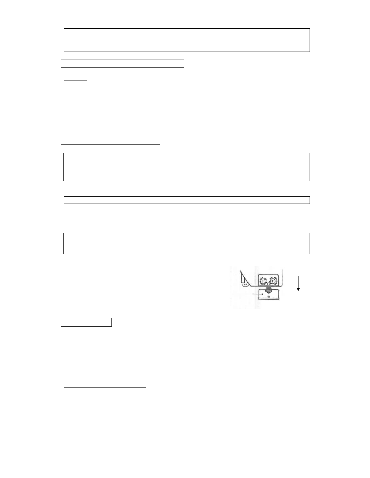
① Disconnect the test leads from any energized circuit.
② Set the function switch to OFF. slide
③ Remove the battery cover screw.
④ Slide of battery cover and change two batteries.
⑤ Set the battery cover and screw. battery cove
WARRANTY
This instrument is sent out from our factory after the sufficient internal inspections
but if you find any defect due to the fault in our workmanship or the original parts,
please contact the dealer where you bought the instrument.
The warranty period is 12 months from the date of purchase and the instrument shall be
repaired at free of charge, provided that we judge the cause of defect is obviously resulted
from our responsibility.
GURANTEE REGULATIONS
1. This instrument is warranted for the operation under normal use for 12 months from
the date of purchase.
2. This warranty does not cover the following defects:
a. Defect caused from the improper use and operation.
b. Defect caused from the use, operation and storage beyond the original specifications,
designs and conditions.
c. Defect caused from the renovations or repairs done by someone else than us or our
representatives.
d. Defect not caused from our responsibilities.
 Loading...