

Page 1

AC/DC CLAMP-ON MILLIAMMETER
Instruction MODEL 600
Manual
Thank you very much for selecting our model 600 digital
AC/DC clamp-on tester.
This model is a complex yet easy to use instrument and
employs a very reliable mechanical/electronic design.
Before using your new instrument, read this Instruction
Manual thoroughly and familiarize yourself with all the
functions. With proper use and care, your tester will give you
years of satisfactory service.
MULTI
Page 2

Contents
1. FEATURES・・・・・・・・・・・ ・・・・・・・・・・・・・ 1
2. SAFETY SUMMARY ・・・・・・・・・・・・・・・・・・・・ 1
3. SPECIFICATION ・・・・・・・・・・・・・・・・・・・・・・ 2
3-1 General Specification ・・・・・・・・・・・・・・・・・・・ 2
3-2 Measuring Range ・・・・・・・・・・・・・・・・・・・・・ 2
4. DIMENSIONS AND PANEL FUNCTION ・・・・・・・・・・・ 3
5. METHOD OF MEASUREMENT ・・・・・・・・・・・・・・・ 5
5-1 Preparation and Caution before Measurement ・・・・・・・・ 5
5-2 Method of Measurement ・・・・・・・・・・・・・・・・・・ 5
5-3 Relative Readings ・・・・・・・・・・・・・・・・・・・・・ 7
5-4 MAX/MIN HOLD Measurement ・・・・・・・・・・・・・・・7
6. REPLACEMENT OF BATTERIES ・・・・・・・・・・・・・・ 8
7. MAINTENANCE ・・・・・・・・・・・・・・・・・・・・・・ 8
Page 3

1. FEATURES
● Extremely high accuracy AC/DC current measurements from 1mA to 10A without
breaking the circuit.
● MAX HOLD and MIN HOLD function provides the monitoring function for
maximum current measurements.
● Automatic zero adjustment function by micro computer for easy operation.
● The double shielding of CT provides minimum influence by the external magnetic
field interference.
2. SAFETY SUMMARY
The WARNINGs which appear on the following page must be followed to ensure
operator safety and to retain the good operating condition of the tester.
Safety Symbols :
△
!
Indicates the operator must refer to an explanation in this manual.
Indicates terminals at which dangerous voltage may exist.
△! WARNING
● To avoid electrical shock, exercise CAUTION when working with more than 60V
DC or 25V AC rms since the danger of electric shock may exist. In addition, check
that the test leads are in normal condition.
● POSSIBLE ELECTRICAL SHOCK. Do not make measurements if the case is
damaged or the battery cover is removed. Remove all electrical inputs before the
battery cover.
● POSSIBLE ELECTRICAL SHOCK or FIRE HAZARD. Do not expose this tester to
rain or moisture. Do not operate the tester in the presence of flammable gases or
fumes.
● Do not exceed the maximum input limits.
● Never clamp the conductor of the circuit carrying 300V or greater.
● Never make measurements for uninsulated conductors or bus bars.
‐1‐
Page 4
3. SPECIFICATION
3-1. General Specification
Measuring sensor : Hall effect
Measuring function : DC current, AC current (true rms reading) with automatic zero
adjustment, max, hold, min, hold, data hold, auto power off
Display : 3.5 digit LCD, max. reading of 1999
Range : AC/DC 200mA, 2000mA, 10A
Sampling time : 1.6 times/sec.
Over range indication : “OL” mark on LCD readout
Data hold indication : "D・H" mark on LCD readout
Low battery indication : "B" mark on LCD readout
Limitation of circuit voltage : Less than AC/DC 300V
Withstanding voltage : AC 2300V/1 minute max. between the core of CT and outer
case.
Operating temperature : 0℃ ~ 50℃, <80%RH (non-condensing)
Storage temperature : -20℃ ~ 60℃, <75% RH (non-condensing)
Power supply : 1.5V (“AA” size, UM-3) x 2
Battery life : 120 hours or more (Alkaline)
Auto power off : The meter is set to power off mode approx. 10 minutes after the
power switch on.
Size : 76(W)x194(H)x30(D)mm
Weight : Approx. 340g
Accessories : Carrying case:……………..1
Instruction manual………1
Batteries……….…………..2
3-2. Measuring Range
Note : Electrical characteristic (18℃ ~ 28℃, 80%RH max.)
Range Input Resolution
A
ccuracy
ACA
200mA 0~199.9mA
100μA ±1.0%rdg±5dgt (50/60Hz)
2000mA 0~1999mA 1mA
±1.0%rdg±5dgt (50/60Hz)
10A 0~9.99A 0.01A
±1.0%rdg±10dgt (50/60Hz)
DCA
200mA
0~±199.9mA 100μA ±1.0%rdg±3dgt±(3%rdg‡)
2000mA
0~±1999mA
1mA
±1.0%rdg±3dgt±(3%rdg‡)
10A
0~±9.99A
0.01A
±1.0%rdg±10dgt±(3%rdg‡)
‡: Error by hysteresis of hall effect.
‐2‐
Page 5
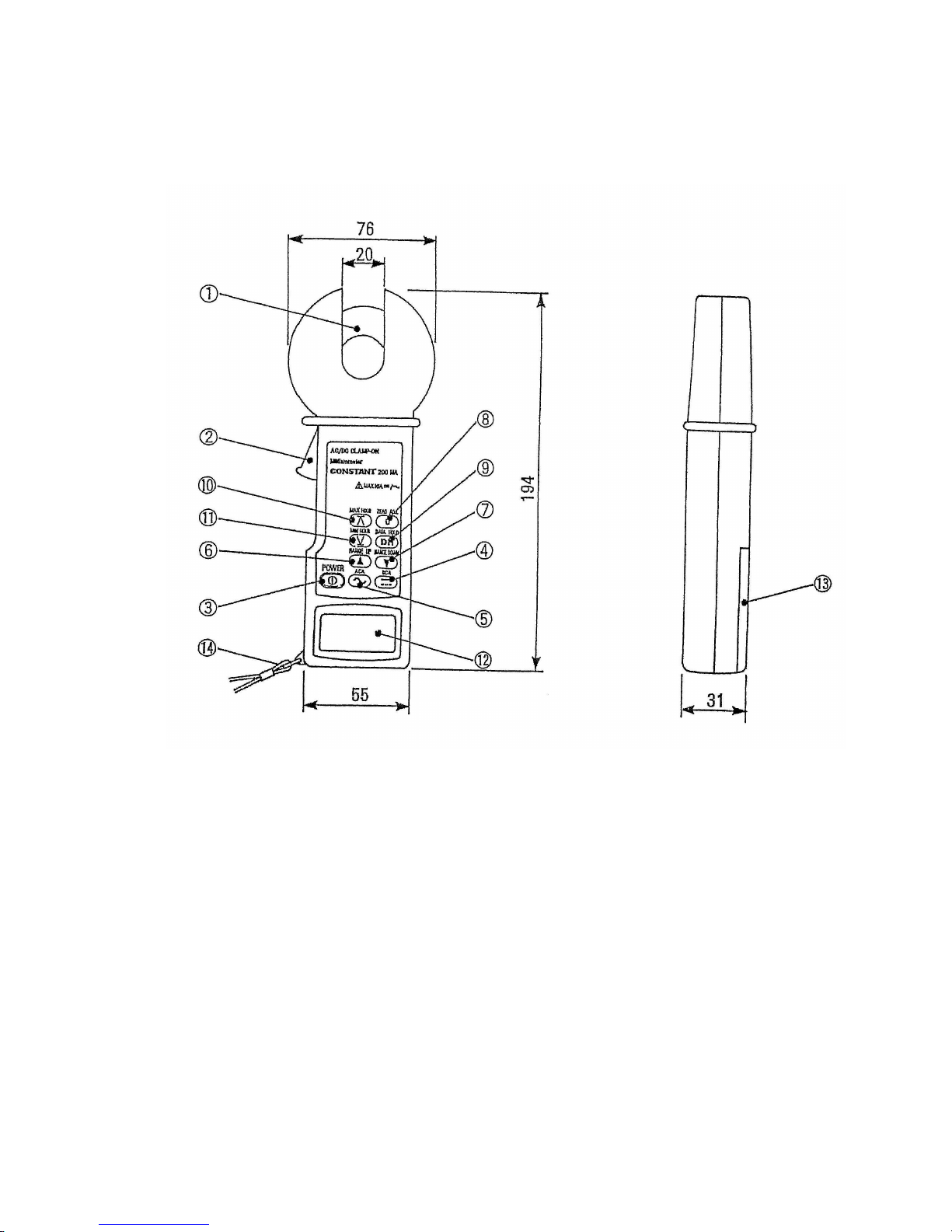
4. DIMENSIONS AND PANEL FUNCTION
‐3‐
Page 6

① Current tra
nsducer (Jaw)
② Jaw opening lever
③ Power switch : Press this switch for power ON or OFF. The meter is set to
power off mode at approximately 10 minutes after the power
switch on. However, in max. hold and min. the auto power off
mode is cancelled.
④ DCA selector switch : Press this switch to select DCA measurements.
⑤ ACA selector switch : Press this switch to select ACA measurements.
⑥ RANGE UP switch : Press this switch to select the range up.
⑦ RANGE DOWN switch : Press this switch to select the range down.
⑧ ZERO ADJ switch : In DCA measurement, this switch is used for zero
adjustment. In ACA measurement, when this switch is
pressed, the input applied at that time is stored as zero
reference point. Subsequent readings display deviations
from this reference point. To release, press DCA/ACA
selector switch or RANGE UP/DOWN switch.
⑨ DATA HOLD switch : This switch locks the display. When pressed. “DH” mark
is displayed. To release, press the switch again to release
the hold condition.
⑩ MAX HOLD switch : Press this switch to select the maximum value
measurement. When pressed, “MAX-H” mark is
displayed. To release, press the switch again.
⑪ MIN HOLD switch : Press this switch to select the minimum value
measurement. When pressed, “MIN-H” mark is
displayed. To release, press the switch again.
⑫ LCD display
⑬ Battery cover
⑭ Wrist strap
‐4‐
Page 7
5. METHOD OF MEASUREMENT
5-1. Preparation and Caution before taking Measurement
● A
void using the tester in places subj
ect to high temperatures, humidity or
excessive vibration.
●
Before measurements, be sure the data hold switch is set to "OFF
". (It is
impossibl
e to make measurements if the data hold switch is set to "ON"
.)
●
Remove the battery if the tester will not be used for
a long period of time.
△
!
WARNING
● T
o avoid electrical shock, exercise CAUTION when working with more than 60V
DC or 25V AC rms since the danger of electric shock may exist. In addition, check
that the test leads are normal condition.
● POSSIBLE ELECTRICAL SHOCK. Do not make measurements if the case is
damaged or the battery cover is removed. Remove all electrical inputs before
removing the battery cover.
● POSSIBLE ELECTRICAL SHOCK or FIRE HAZARD. Do not expose this tester to
rain or moisture. Do not operate the tester in the presence of flammable gases or
fumes.
● Do not exceed the maximum input limits.
● Never clamp the conductor of the circuit carrying 300V or greater.
● Never make measurements for uninsulated conductors or bus bars.
5-2. Method of Measurement
Important Note :
Model 600 employs the hall effects for the CT censor. The characteristics of the hall
effect have a hysteresis due to magnetization. It means the zero adjustment point is
varied in DC current measurement. To eliminate this effect, open and close the jaws
several times to discharge and always press zero adjustment switch before measure-
ments.
For reference, when DC 10A conductor is clamped, 100mA indication by magnetization
is observed in our test.
The high sensitive hall effect sensor is used in CT. When clamping the conductor, open
and close the jaws slowly and firmly to avoid the impact to the sensor.
‐5‐
Page 8
① Set the POWER switch to "ON". The function is automatically set to DC
200mA range.
② Set the ACA/DCA selector switch to ACA or DCA depending upon the signal to
be measured.
③ Set the range to the appropriate range using RANGE UP or RANGE DOWN
switch.
④ Press ZERO ADJ switch to read zero for the DC current measurement. When
pressed, “ZERO ADJ” mark is displayed. In DCA measurement, always carry
out the zero adjustment before measurements. To repeat the zero adjustment,
press to release RANGE UP or RANGE DOWN switch.
⑤ Clamp slowly and firmly around the conductor of the circuit under test with
the current transducer.
⑥ Taking measurements in a dark place or in a place where it is difficult to see
readings, use the data hold switch.
⑦ Read the displayed value.
⑧ After measurement, set the POWER switch to “OFF”.
CAUTION
The various numerals are indicated in the display in DC current measurement, even
when the clamp transducer (Jaw) is opened or closed without any input. However, this
is not abnormal. Always carry out the zero adjustment before measurements.
Note : Clamp around only one conductor in the circuit to be measured for the line
current or earth line measurement.
To measure a leakage current in a single-phase electric circuit, clamp the
two conductors together. Or clamp the three conductors together in the case
of the three-phase electric circuit.
CAUTION
Nev
er fail to keep the maximum tolerable input.
To avoid electrical shock or damage, the measurement is limited to the circuit 20A DC
or AC rms.
‐6‐
Page 9
5-3. Relative Readings
If the ZERO ADJ switch is pressed in ACA measurement mode, the input applied at
the time is stored as a zero reference point.
① When ZERO ADJ switch is pressed under the clamping condition, “ZERO ADJ”
mark is displayed with the indication of 0.0, 0 or 0.00.
② The deviations from this point are displayed for subsequent measurement.
5-4. MAX/MIN HOLD Measurement
This function is used to measure the maximum value or minimum value in the
measurements. In this mode, the auto power off function is automatically canceled.
① Set the POWER switch to "ON".
② Set the ACA/DCA selector switch to ACA or DCA depending upon the signal to be
measured.
③ Set the range to the appropriate range.
④ Press the ZERO ADJ switch to read zero for the DC current measurement.
⑤ Clamp the conductor of the circuit under test with clamp transducer..
⑥ Read the displayed value. Press the MAX HOLD or MIN HOLD switch once,
“MAX-H” or “MIN-H” mark is displayed. In this mode, the maximum value or
minimum value is displayed for subsequent measurement. To release, press the
switch again.
⑦ After measurement, set the POWER switch “OFF”.
CAUTION
If ex
cessive high current is applied to the clamp transducer, the zero adjustment
is disabled due to the magnetic charge of the clamp transducer. In such case,
discharge the magnetized clamp transducer as follows.
① Set the POWER switch to "ON".
② Set the range to AC 200mA range.
③ Apply AC 10A to the clamp transducer (by clamping), and reduce the applied
current gradually to zero. The magnetic charge will be discharged.
‐7‐
Page 10
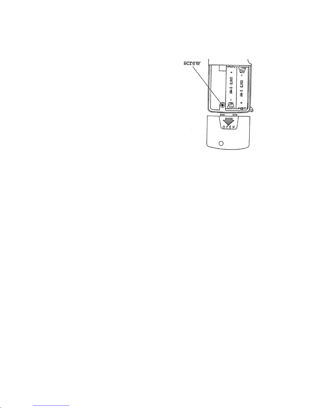
6. REPLACEMENT OF BATTERIES
When the battery becomes exhausted
or drops below the operating voltage,
the "B" mark is displayed.
Set the power switch to "OFF", prior
to installing batteries.
To install the batteries, remove
the battery cover located at the
rear.
Loosen the screw on the battery cover.
Replace the batteries (AA size or
UM-3) with new ones, observing polarity.
Use high-quality batteries which are
guaranteed against leakage. If the
tester is to be left unused for a long
period of time, to prevent damage due
to possible leakage, remove the batteries.
7. MAINTENANCE
When maki
ng requests for repair service, please bring the instrument directly to
the dealer. If this is impossible, however, send the instrument directly to our sales
office.
When mailing this instrument, always pack it in its original or equivalent packing
material and pack together with name, address, telephone number and the
warranty documentation.
● To endure speedy and reliable repair, always include information as the type of
failure and cause.
● If required, always return accessories with the instrument.
● When contacting us, provide the model number and serial number of your
instrument.
‐8‐
Page 11

MULTI MEASURING INSTRUMENTS CO.,LTD.
Akihabara Murai Bldg. 7F, 1-26, Kanda Sakuma-cho,
Chiyoda-ku, Tokyo, 101-0025 Japan
TEL : 81-3-3251-7013 FAX : 81-3-3253-4278
Home Page : http://www.multimic.com/
E-mail : [email protected]
 Loading...