

Multenet PocketPAD RS-232, PocketPAD RS-422, PocketPAD Power over Ethernet, PocketPAD RS-485 User Manual
MULTeNET PocketPAD
Low Cost Serial to Ethernet Devices
User Manual
PocketPAD RS-232
PocketPAD RS-232/422/485
PocketPAD Power over Ethernet
English
Version 2.2
March 2005
PocketPAD

2 2
M U LT E N E T P O C K E T PA D
Document Scope
This manual describes how to install, configure and operate the PocketPAD Serial to Ethernet
converters. For updated product features, refer to our website at www.multenet.com
Revision History
Revision No Changes
1.0 First Release.
2.0 Includes PocketPAD FX.
2.1
PocketPAD FX to new manual.
New Idle Timeout feature added.
2.2 Includes Power over Ethernet product.
Data, Illustrations, Alterations
The data and illustrations found in this document are not binding. We reserve the right to
modify our products in line with our policy of continuous product development. The information
in this document is subject to change without notice and should not be construed as a
commitment by MULTeNET.
MULTeNET assumes no responsibility for any errors that may appear in this document.
If you have any suggestions for improvement or amendment, or have found errors in this
publication, please notify us through your distributor or email techsupport@multenet.com
Trademarks
EtherPAD and PocketPAD are registered Trademarks of MULTeNET. Internet Explorer,
Windows 95/98/2000/NT/XP are registered trademarks of Microsoft Corporation. Ethernet is a
trademark of XEROX Corporation. Modbus is a trademark of Schneider Electric, Inc.
Copyright 2005 MULTeNET. All rights reserved.
Contact details:
2201 Midway Road
Suite 302
Carrollton
TX75006
United States
Sales Email : sales@multenet.com
Technical Support Email : techsupport@multenet.com
Website : http://www.multenet.com

3 3
M U LT E N E T P O C K E T PA D
Document Contents
INTRODUCTION
Introduction to PocketPAD 7
COM Port Redirection 7
Different Ethernet Interfaces Available 8
Multiple Network Connections 9
Power-Over-Ethernet 10
Power-Over-Serial 11
Security 11
Firmware Updates 11
GETTING STARTED
Identifying your PocketPAD 13
Connecting the PocketPAD 14
10/100 Base-T Ethernet Network Connection 14
Serial Port Connection 15
Configuring PocketPAD RS-232/RS422/RS485 units 16
RS485 (Half Duplex) Configuration 17
RS422 (Full Duplex) Configuration 18
RS232 Configuration 19
Configuring the PocketPAD 20
Discovering PocketPADs 20
CONFIGURATION
Configuration Overview 24
MAC addresses 24
Configuration File Upload 24
Web Browser Configuration 25
Check your web browser proxy settings 25
Log into Web Configuration 25
Web Configuration 26
Menu Header 26
Save/Reboot 27
Info 27
Management 28
Passwords 28
System Information 28
Troubleshooting 28
View Configuration File 29
System Log 29

4 4
M U LT E N E T P O C K E T PA D
Networking 30
Ethernet Parameters 30
Advanced Routing 31
Domain Name Servers 31
SNMP Settings 32
Serial Application 32
Serial Interface Settings 34
Application Type 35
Reset to Factory Defaults 37
Serial or Telnet Configuration 38
Serial Connection 38
Telnet Connection 38
Menu Configuration 38
Management Settings 39
Networking 39
Ethernet Interfaces 40
Routing 40
Name Servers 41
SNMP 41
Serial Interfaces 41
Applications 43
TCP Applications 43
UDP Applications 46
Reset to Factory Defaults 48
DHCP/BootP with TFTP Configuration 48
Configuration using DHCP/BootP 49
Configuration using TFTP 49
An Example of a TFTP File Format (PocketPAD 1) 49
UPGRADING
Serial Firmware Upgrade (KERMIT) 52
Logging into Serial Configuration mode 52
Upgrading the Firmware 53
Firmware Upload Errors 54
Change Password 55
Erase Dataflash 55
Perform Integrity Check 55
TROUBLESHOOTING
Verifying MAC Addresses 56
Ping 57
ARP 57
Traceroute 57
Telnet 58
Web Browser Proxy Settings 58

5 5
M U LT E N E T P O C K E T PA D
Recovering from a Lost Password 60
Troubleshooting LEDs 61
System 61
Serial Interface 61
Network Interface - 10/100 Base-T 61
APPENDIX
Product Specification 64
PocketPAD 1 64
PocketPAD 2 65
PocketPAD 4 66
PocketPAD 1 RS 232/485/422 67
PocketPAD 2 RS 232/485/422 68
PocketPAD 4 RS 232/485/422 69
PocketPAD Power over Ethernet 70
Interface Pin-outs 71
Network Interface 71
Serial Interface 71
Cables 72
Straight 10/100 Base-T Ethernet Cable 72
Crossed 10/100 Base-T Ethernet Cable 72
Crossed Serial Cable 72
Full Crossed Serial Cable 73
Null-Modem Crossed Serial Cable 73
Straight Serial Cable 74
END USER SOFTWARE LICENCE AGREEMENT
1. THE LICENCE 75
2. USE OF THE SOFTWARE 75
3. LICENSEE’S UNDERTAKINGS 75
4. LIMITED WARRANTIES 76
5. LIMITATION OF LIABILITY 76
6. COPYRIGHT, PATENTS, TRADE MARKS AND OTHER INTELLECTUAL PROPERTY
RIGHTS 77
7. TERMINATION 77
Limited Warranty 77
1. WHAT THIS LIMITED WARRANTY COVERS AND FOR HOW LONG: 77
2. WARRANTY CONDITIONS: 77
3. WHAT THIS LIMITED WARRANTY DOES NOT COVER: 78
4. HOW TO GET WARRANTY SERVICE: 78
5. GENERAL PROVISIONS: 78
6. DISCLAIMER OF ALL OTHER WARRANTIES: 78
7. LIMITATION OF LIABILITiES: 78
NOTES

6 I N T R O D U C T I O N 6
M U LT E N E T P O C K E T PA D
INTRODUCTION
The PocketPAD is a low cost Serial to Ethernet device server. This light weight device can
be used as stand-alone or mounted on a DIN rail. The PocketPAD connects asynchronous
serial devices to Ethernet networks.
The PocketPAD base range has RS-232 Serial interfaces with a single 10/100 Base-T
Ethernet interface.
The PocketPAD 1 has a single Serial interface.
The PocketPAD 2 has two Serial interfaces.
The PocketPAD 4 has four Serial interfaces.
The PocketPAD Power over Ethernet has a single Serial interface with PoE enabled 10/100
Base-T Ethernet interface.
The PocketPAD RS 232/422/485 range has a single RS-232/RS-485/RS-422 Serial interface
with a single 10/100 Base-T Ethernet interface. Internal dip switches are available to configure
the type of serial line and its termination.
The PocketPAD 1 RS 232/422/485 has a single RS-232/RS-485/RS-422 Serial interface.
The PocketPAD 2 RS 232/422/485 has one RS-232/RS-485/RS-422 Serial interface and
one RS-232 Serial interface.
The PocketPAD 4 RS 232/422/485 has one RS-232, RS-485, RS-422 Serial interface and
three RS-232 Serial interfaces.
7 I N T R O D U C T I O N 7
M U LT E N E T P O C K E T PA D
Introduction to PocketPAD
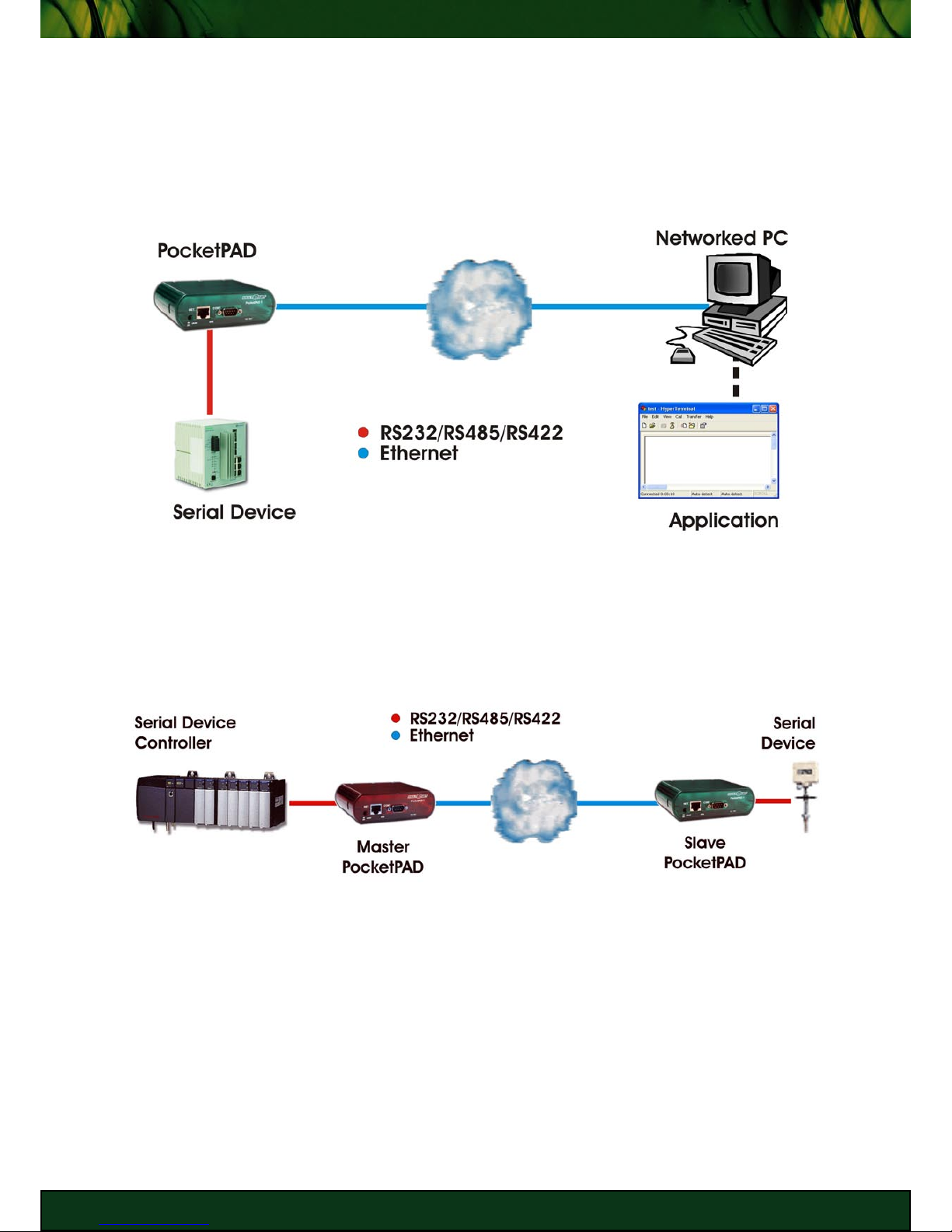
The PocketPAD is a device that interconnects serial and Ethernet systems. The networked
host could have a server application polling for information from the serial unit, or a controller
with an Ethernet port. The PocketPAD can be configured to be a server (Passive/Slave mode)
or a host (Active/Master mode).
Serial to PC (Ethernet)
The PocketPAD also provides a transparent serial link over the Ethernet network between two
serial devices, when used with another PocketPAD. This extends your serial line beyond its
limitations. The Ethernet network can be used instead of laying down extra serial cable lines.
Serial to Serial
COM Port Redirection
A COM Port Redirector software tool can be employed to provide a virtual COM Port which is
tunnelled through to the PocketPAD via Ethernet for server applications that are not network
enabled (i.e. legacy systems).
The COM port redirector on the PC creates a virtual serial port for use by the serial software
application. The COM port redirector is responsible for passing data and control signals to the
8 I N T R O D U C T I O N 8
M U LT E N E T P O C K E T PA D
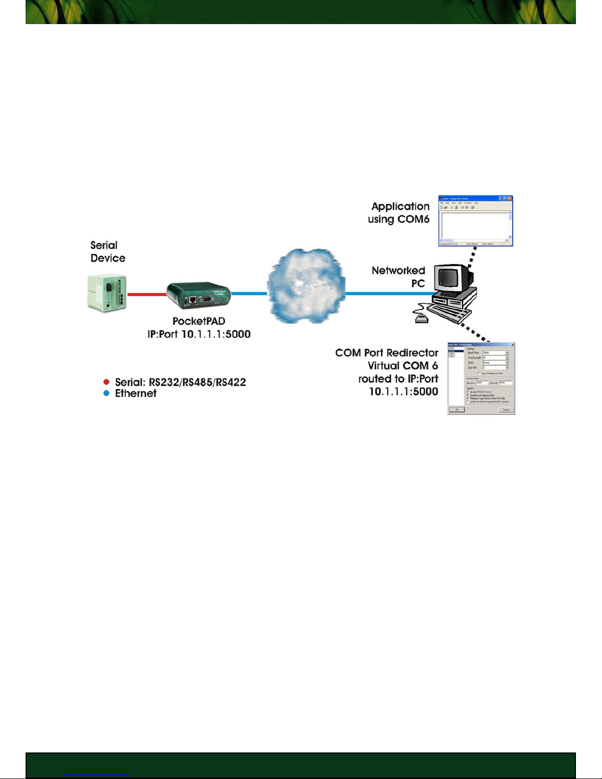
PocketPAD, which in turn sends data to the connected serial device.
In the example below the application software running on the networked PC is only capable
of connecting to serial Com ports (i.e from COM1 to COM6) and not to an IP address. As the
PC has only two physical com ports, COM1 and COM2, you would create a virtual port (i.e.
COM6), using the redirector software. The redirector is then configured to connect COM6 to
the IP address of the PocketPAD connected to the remote serial device. When the application
sends to or requests data from the serial device, it connects to the device via COM6.
This is very useful when upgrading hardware and/or software to incorporate Ethernet support
proves to be too expensive.
Serial to Host’s Virtual COM Port
The COM port redirector software tools have two modes of transporting packets over the
Ethernet link:
The first method, Raw, streams the data through seamlessly. Configure the PocketPAD to
use ‘Raw’ as its network application protocol.
The second method, Redirector, involves the Telnet protocol (RFC-2217: Telnet Com Port
Control Option). If your software application changes the serial paramters used (i.e. varied
baud rates, data bits, stop bits, flow control, parity), you should use the Telnet Redirector
option. Remember to configure the PocketPAD’s network application to ‘Redirector’ as
well.
Different Ethernet Interfaces Available
Two Ethernet interfaces are available:
Copper: 10/100 Base-T with RJ-45 connector
10 Base-T: Supports a 10 Mbps data rate on UTP cable. The LAN segment length is only
100m.

9 I N T R O D U C T I O N 9
M U LT E N E T P O C K E T PA D
100 Base-T (Fast Ethernet): Supports a 100 Mbps data rate over UTP cable segments of
100m. This type of Ethernet is very common in the business workplace.
The next level up is Giga Bit Ethernet (1 Gbps - 1000 Base-T).
RJ45 connectors
Fiber: 100 Base FX (MultiMode) with SC connector
Supports a 100 Mbps data rate for Ethernet over fiber optic cabling. TIA/EIA-568-A standard
requires 62.5/125 µm multimode fiber and “SC” connectors for new installations. In addition,
100 Base-FX requires a minimum of two 62.5/125 µm multimode fibers, one for transmit data,
and one for receive data.
The advantages of using fiber optic medium are that it can be used in areas with a electromagnetic interferences, long distance cable runs, and in backbone cabling carrying high
bandwidth.
Multimode fiber gives you high bandwidth at high speeds over medium distances. The
bandwidth is specified for 1 km (or approx. 3280 ft.). Shorter runs would have less dispersion
and therefore be higher bandwidths. Longer runs would have greater dispersion and therefore
have less bandwidth. Light waves are dispersed into numerous paths, or modes, as they
travel through the cable’s core (typically 850 or 1300nm).
Fiber SC Connectors
Multiple Network Connections
The PocketPAD can maintain multiple simultaneous socket connections on its configured
Ethernet ports. Passive/Slave applications are simply ports set to accept incoming
connections from remote hosts. Active/Master applications are configured to connect to
remote servers (whether it be another PocketPAD in Passive mode or a PC server application).
Connected hosts will receive data arriving in at the serial interface. Any data sent from the
remote hosts will be directed out to the connected serial device.

10 I N T R O D U C T I O N 10
M U LT E N E T P O C K E T PA D
For example, many networked computers can access data streamed from a temperature
sensor connected to the PocketPAD.
Another example would be a Master PLC (Programmable Logic Controller) connected to
multiple serial process control devices via PocketPADs.
The number of applications are limitless.
You could also configure your PocketPAD to be both Active (Master) and Passive (Slave). A
maximum of 5 TCP and/or UDP network applications can be configured on the PocketPAD.
Each application can handle 5 socket connections (i.e. Total of 25 concurrent socket
connections at any one time when 5 Passive mode applications are configured).
One major advantage having multiple sockets available is that you are not isolated to monitor
and control remote serial devices from one location. You can simply connect from any part of
the network and continue working. This does depend on how your network is setup and also
the security measures installed on the network (check with your network administrator).
Power-Over-Ethernet
A PocketPAD Power over Ethernet (PoE, IEEE802.3af) device is available should you not wish
to use a power supply unit. You will need a Power injector to power this unit via the Ethernet
cable.

11 I N T R O D U C T I O N 11
M U LT E N E T P O C K E T PA D
Power-Over-Serial
Should you have a serial device which obtains it’s power via the serial link, then you can set
the PocketPAD to provide this power. You will need to check the power requirement of the
serial device to make sure the PocketPAD is compatible.
Contact us for more details on this feature.
Security
Securing your PocketPAD is done on various levels. Authentication is required for configuring
the PocketPAD. The administrator username is ‘root’ with the default password being ‘xxx’. It
is recommended that you change this password if you expect unwanted connections to the
PocketPAD.
NOTE: DO NOT lose your password. If both the Bootloader and System passwords are
lost, you will need to send your PocketPAD back to MULTeNET to recover the
change. There is a cost associated with this recovery procedure. You are able to
recover from a lost System password by erasing the Dataflash using the Bootloader
login.
Allow specific remote hosts to connect to the PocketPAD’s Ethernet ports. When setting your
PocketPAD’s network application, you can set the IP Address and Port Number of the remote
host which is allowed to connect to the PocketPAD. In Passive/Slave mode, the PocketPAD
will only accept connections from the remote host with the specified details configured on the
PocketPAD. Other remote hosts which try to connect to the PocketPAD will be denied access
to the serial data stream.
Firmware Updates
MULTeNET continues to develop its products extensively, with new firmware releases
available regularly. New releases may contain new protocols, new features, bug fixes, new
routines resulting in better performances.
These firmware updates can be downloaded off the MULTeNET FTP server at:
ftp://multenet_guest:download@ftp.multenet.com/pocketpad/firmware/
Username = multenet_guest
Password = download
FTP server hostname = ftp.multenet.com
Directory location = /pocketpad/firmware/
Alternatively, contact your local distributor or email Technical Support.

12 G E T T I N G S TA R T E D 12
M U LT E N E T P O C K E T PA D
GETTING STARTED
This chapter provides information on connecting your PocketPAD to the network.
13 G E T T I N G S TA R T E D 13
M U LT E N E T P O C K E T PA D
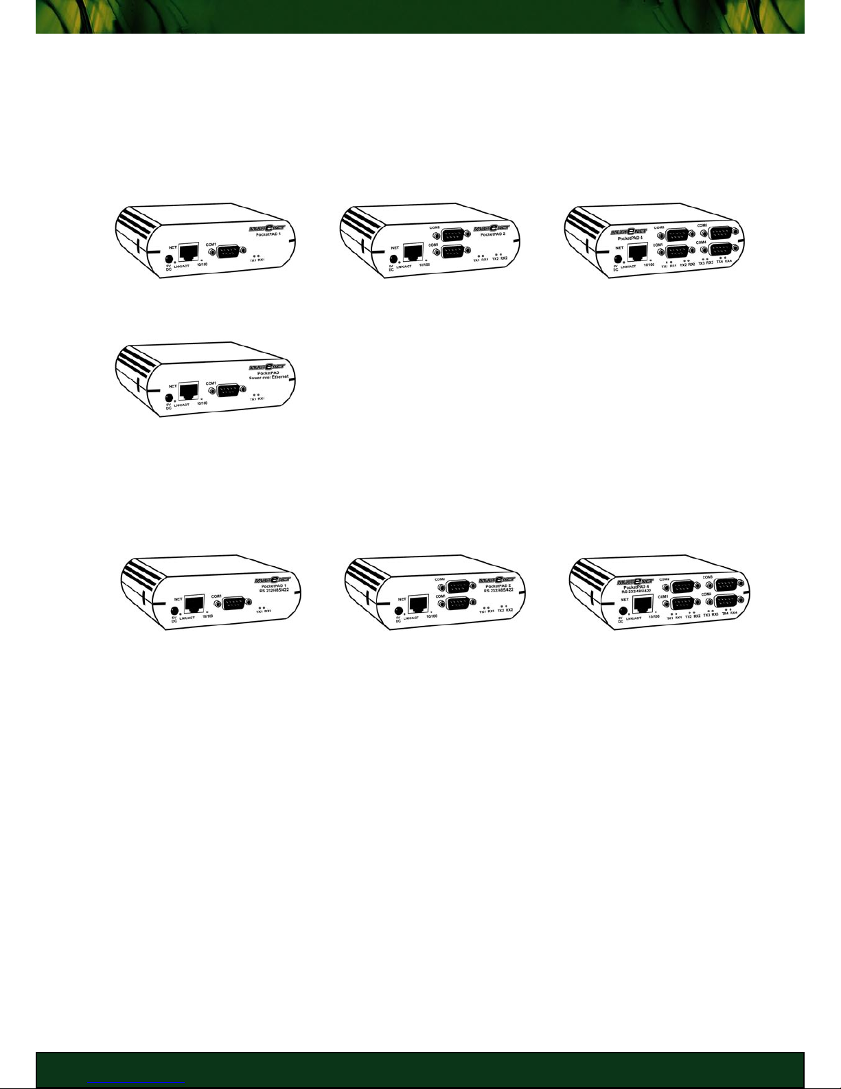
Identifying your PocketPAD
The PocketPAD ranges differ in the type and number of interfaces available. The labels on the
faceplate should help identify which product you have.
RS 232 Serial to 10/100 Base-T Ethernet PocketPAD Range
PocketPAD 1 PocketPAD 2 PocketPAD 4
PocketPAD Power over
Ethernet
RS 232, RS 485, RS 422 Serial to 10/100 Base-T Ethernet PocketPAD Range
PocketPAD 1
RS 232/485/422
PocketPAD 2
RS 232/485/422
PocketPAD 4
RS 232/485/422

14 G E T T I N G S TA R T E D 14
M U LT E N E T P O C K E T PA D
NET
10/100 Base-T
Ethernet Port
COM
Serial Port
RX LED
Lights when
serial data is
received.
TX LED
Lights when
serial data is
sent.
10/100 LED
Ethernet speed
indication:
ON = 100 Mbps
OFF = 10 Mbps
LNK/ACT LED
Flashes when activity
is seen on the network.
OFF if network is
disconnected.
Power
LED
ON when
device is
powered
up.
5V DC
Power
200 mA
Heartbeat
LED
Flashes
during normal
operation.
If solidly lit
there is a
problem.
10/100 Base-T PocketPAD
Connecting the PocketPAD
You can physically connect to the PocketPAD via two interfaces (serial port & Ethernet port).
COM 1 can be used to configure the unit on all the PocketPAD ranges. Configuration occurs
when the device boots up. It is indicated by the flashing TX and RX LEDs (defaulted to 20
seconds).
The easiest configuration method is via the Ethernet network using a web browser. The GUI is
simple and easy to navigate through the options.
10/100 Base-T Ethernet Network Connection
There are two ways to connect to your PocketPAD via the Ethernet Network:
- Via a 10/100 Base-T Hub or Switch, using a “Straight” Ethernet cable.
- Direct connection from the PC, using a “Crossed” Ethernet cable.

15 G E T T I N G S TA R T E D 15
M U LT E N E T P O C K E T PA D
PocketPAD configuration via a Hub
PocketPAD configuration via a Workstation Network Card
Serial Port Connection
The PocketPAD is a DTE (Data Terminal Equipment) device. You need to choose the serial
cable best suited to your serial device. A number of cable options are available:
• Crossed Serial Cable (most commonly used).
• Full Crossed Serial Cable.
• Null-Modem Crossed Serial Cable. Connect to another DTE (Data Terminal Equipment)
device, such as a PC.
• Straight Serial Cable. Connect to a DCE (Data Communications Equipment) device such
as a Modem.
Connecting PocketPAD & PC serial ports together
NOTE: Only COM 1 has a full compliment of Serial line signals. Extra Serial interfaces on the
PocketPAD 2 and PocketPAD 4 contain the following signals on the each COM port:
CTS, RTS, TX, RX, GND

16 G E T T I N G S TA R T E D 16
M U LT E N E T P O C K E T PA D
Configuring PocketPAD RS-232/RS422/RS485 units
Onboard DIP switches provide control over the serial interface mode.
TERMINATION: Take note of the termination on your RS422 or RS485 network. There are a
number of methods to configure the network.
If impedances at cable ends are mismatched, the load will not absorb
transmitted signals resulting in reflections back along the data line.
Terminations are not required on slow data speeds (i.e. 9600 baud) and short
cable lengths. The reflections are absorbed (damped out) and the signal
stabilised by the time a reading is taken.
The termination resistance should match the impedance of the network
(generally a 100 Ω/120 Ω resistor is connected between the two wires). You
will need to check the cable manufacturer’s specifications. Only 2 terminating
resistors are required and must be placed at the extreme ends of the cable.
Termination can be enabled via the DIP switches if the PocketPAD is inserted
at the end/start of the network. If you place the PocketPAD into the ‘middle’
of the network, you should disable the termination via the DIP switches.
Terminating DIP switches are ‘DIP1 - 1’ & ‘DIP1 - 2’.
NOTE: Opening the PocketPAD is done at your own risk. You need to take the necessary
precautions. MULTeNET cannot take responsibility for damage done when
you open the unit. Refer to the warranty for more details.
Procedure for dip switch configuration of the unit:
• Disconnect the power from the PocketPAD.
• Open your PocketPAD. Gently pop the front face off by pushing the side latches in.
• Slide the board out.
• Configure the dip switches according to the following tables describing RS232, RS422 or
RS485 interfaces. Take note that you may require termination if the PocketPAD is at either
end of the RS485 network.
• Slide board back and reinsert faceplate. Ensure that the side latches have engaged.
• Connect the power.
CAUTION: It is advised that you take preventative measures to ensure that you do not
discharge electrostatic signals which may damage the device.
17 G E T T I N G S TA R T E D 17
M U LT E N E T P O C K E T PA D
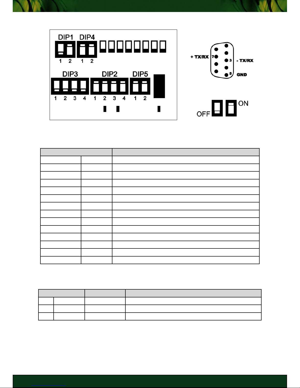
RS485 (Half Duplex) Configuration
KEY
DB9 Male Interface
RS485 Termination Enabled
PIN DESCRIPTION
DIP1 - 1 RX TM OFF
DIP1 - 2 TX TM ON (if placed at beginning/end of network - Terminated)
DIP2 - 1 RX- ON (RS422/RS485)
DIP2 - 2 TX- ON (RS422/RS485)
DIP2 - 3 TX+ ON (RS422/RS485)
DIP2 - 4 RX+ ON (RS422/RS485)
DIP3 - 1 HRX- OFF (RS232)
DIP3 - 2 HTX- OFF (RS232)
DIP3 - 3 HTX+ OFF (RS232)
DIP3 - 4 HRX+ OFF (RS232)
DIP4 - 1 RX+/TX+ ON (Half Duplex - RX+ = TX+)
DIP4 - 2 RX-/TX- ON (Half Duplex - RX- = TX-)
DIP5 - 1 - DIP5 - 2 SEL ON (enable RS422/RS485 operation)
RS485 (Half Duplex) DIP Switch Settings
PIN SIGNAL DESCRIPTION
3 TX-/RX- OUT DATA NEGATIVE
5 GND - SIGNAL GROUND
7 TX+/RX+ OUT DATA POSITIVE
RS485 DB9 Serial Interface Pinout
18 G E T T I N G S TA R T E D 18
M U LT E N E T P O C K E T PA D
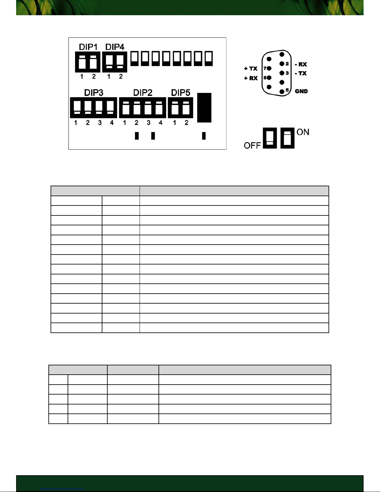
RS422 (Full Duplex) Configuration
KEY
DB9 Male Interface
RS422 Termination Enabled
PIN DESCRIPTION
DIP1 - 1 RX TM ON (if placed at beginning/end of network - Terminated)
DIP1 - 2 TX TM ON (if placed at beginning/end of network - Terminated)
DIP2 - 1 RX- ON (RS422/RS485)
DIP2 - 2 TX- ON (RS422/RS485)
DIP2 - 3 TX+ ON (RS422/RS485)
DIP2 - 4 RX+ ON (RS422/RS485)
DIP3 - 1 HRX- OFF (RS232)
DIP3 - 2 HTX- OFF (RS232)
DIP3 - 3 HTX+ OFF (RS232)
DIP3 - 4 HRX+ OFF (RS232)
DIP4 - 1 RX+/TX+ OFF (Full Duplex)
DIP4 - 2 RX-/TX- OFF (Full Duplex)
DIP5 - 1 - DIP5 - 2 SEL ON (enable RS422/RS485 operation)
RS422 (Full Duplex) DIP Switch Settings
PIN SIGNAL DESCRIPTION
2 RX- IN RECEIVE DATA NEGATIVE
3 TX- OUT TRANSMIT DATA NEGATIVE
5 GND - SIGNAL GROUND
7 TX+ OUT TRANSMIT DATA POSITIVE
8 RX+ IN RECEIVE DATA POSITIVE
RS422 DB9 Serial Interface Pinout
19 G E T T I N G S TA R T E D 19
M U LT E N E T P O C K E T PA D
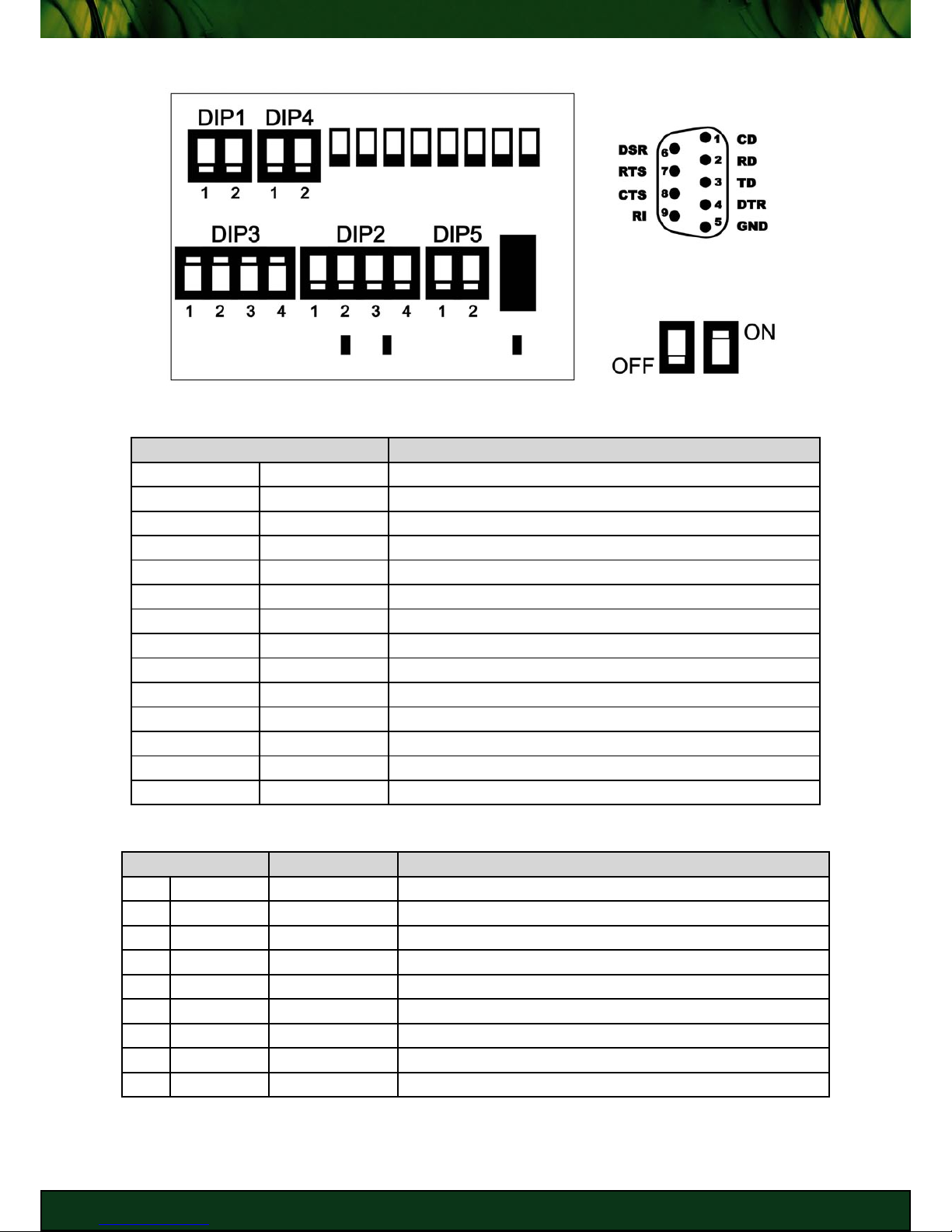
RS232 Configuration
KEY
DB9 Male Interface
RS232 Enabled
PIN DESCRIPTION
DIP1 - 1 RX TM OFF
DIP1 - 2 TX TM OFF
DIP2 - 1 RX- OFF (RS422/RS485)
DIP2 - 2 TX- OFF (RS422/RS485)
DIP2 - 3 TX+ OFF (RS422/RS485)
DIP2 - 4 RX+ OFF (RS422/RS485)
DIP3 - 1 HRX- ON (RS232)
DIP3 - 2 HTX- ON (RS232)
DIP3 - 3 HTX+ ON (RS232)
DIP3 - 4 HRX+ ON (RS232)
DIP4 - 1 RX+/TX+ OFF
DIP4 - 2 RX-/TX- OFF
DIP5 - 1 - OFF
DIP5 - 2 SEL OFF (enable RS232 operation)
RS232 DIP Switch Settings
PIN SIGNAL DESCRIPTION
1 CD IN CARRIER DETECT
2 RD IN RECEIVE DATA
3 TD OUT TRANSMIT DATA
4 DTR OUT DATA TERMINAL READY
5 GND - SIGNAL GROUND
6 DSR IN DATA SET READY
7 RTS OUT REQUEST TO SEND
8 CTS IN CLEAR TO SEND
9 RI IN RING INDICATOR
RS232 DB9 Serial Interface Pinout

2 0 G E T T I N G S TA R T E D 2 0
M U LT E N E T P O C K E T PA D
Configuring the PocketPAD
There are a number of methods to configure the PocketPAD:
• Configuration File Upload
• Web Browser Configuration
• Serial Configuration
These configuration methods will be explained in the next chapter.
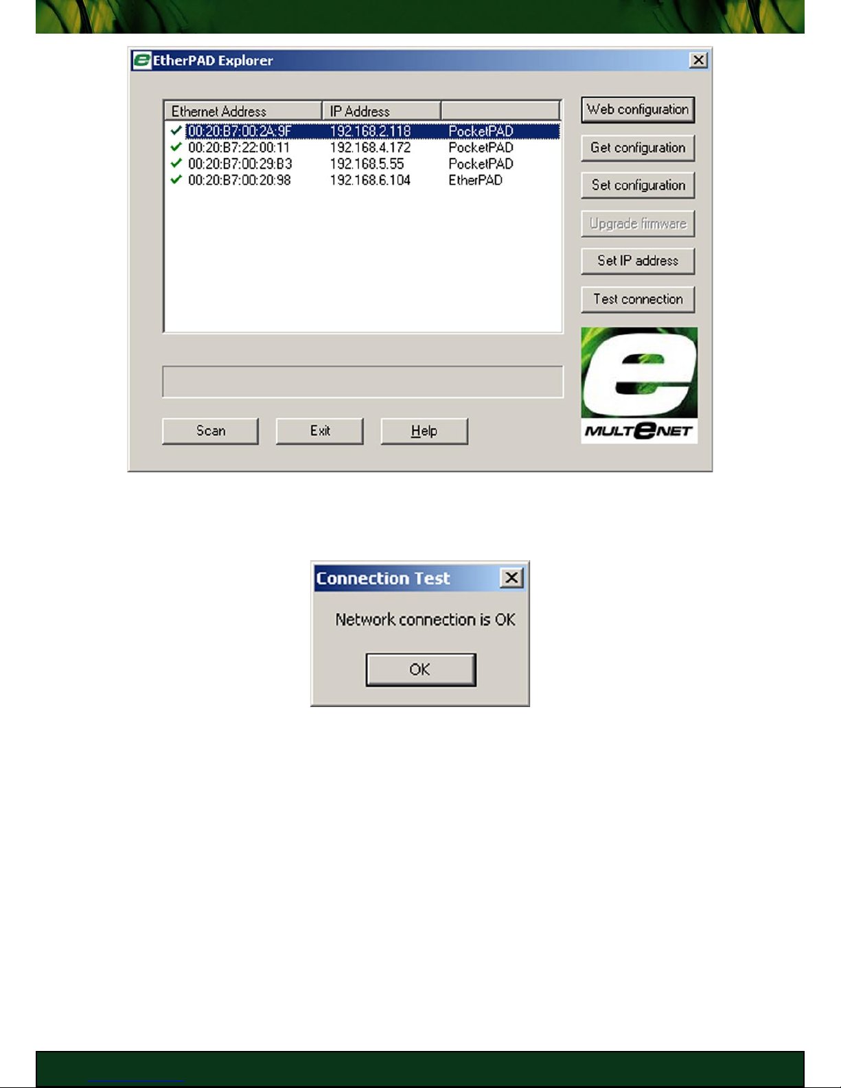
Discovering PocketPADs
Launch EtherPAD Explorer. EtherPAD Explorer executable is available on the
MULTeNET Product CD, along with the installation for MS Windows PCs.
Select [Run EtherPAD Explorer now] from the Autorun Menu to launch the executable from
the CD, or click [EtherPAD Explorer] for other options relating to EtherPAD Explorer.
Click [Scan] in EtherPAD Explorer to find PocketPADs and other MULTeNET products
on the local segment. A broadcast is sent out to which MULTeNET products respond
to. A new device will have no IP Address set, unless a DHCP server is setup and has issued
the PocketPAD an IP Address. Identify the MAC Address on the PocketPAD to verify that the
unit is online. PocketPADs on remote segments and networks will not be seen by EtherPAD
Explorer as routers will block the broadcast.
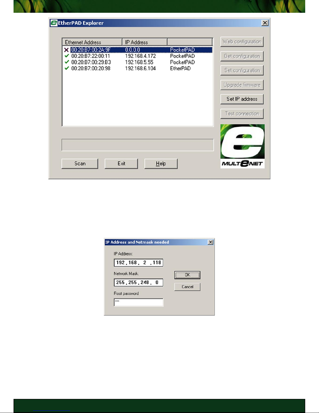
2 1 G E T T I N G S TA R T E D 21
M U LT E N E T P O C K E T PA D
You will need to [Set IP Address] to configure the PocketPAD via TCP/IP. Make sure the IP
Address falls in your local subnet. Ask your Network Administrator should you have issues
getting these details. The default Root password is ‘xxx’. If an IP Address has already been
set, it may be that the DHCP server has assigned the network parameters. The PocketPAD, by
default, is set to obtain an IP Address from a DHCP server.
2 2 G E T T I N G S TA R T E D 2 2
M U LT E N E T P O C K E T PA D
You can [Test connection] to check if the PocketPAD is reachable via TCP/IP. If the test fails,
check your IP Address and Subnet Mask settings. Check the Troubleshooting Guide for more
fault-finding tips.
Check that the IP Address you enter is not used by another host on the network. Duplicate IP
Addresses may cause unwanted network disruptions.

2 3 C O N F I G U R AT I O N 2 3
M U LT E N E T P O C K E T PA D
CONFIGURATION
This chapter provides information on configuring your PocketPAD.

2 4 C O N F I G U R AT I O N 2 4
M U LT E N E T P O C K E T PA D
Configuration Overview
There are a number of methods to configure the PocketPAD:
• Configuration File Upload via network using EtherPAD Explorer.
• Web Browser Configuration via network using a Web Browser.
• Serial Configuration via the serial link using a terminal application.
• Telnet Configuration via network using a terminal application.
• DHCP/BootP with TFTP automatically via network servers.
Three steps are required to configure the PocketPAD for operation:
1. Configure the PocketPAD’s IP Address, Network Mask and Gateway IP Address.
2. Configure the Serial communication parameters.
3. Configure network applications.
MAC addresses
When the PocketPAD leaves the factory, the only address associated with it will be its
universally unique Ethernet address. This is also referred to as the MAC (Media Access
Control) address. The MAC address is programmed at the factory and cannot be modified.
It is a 12-digit hexadecimal number and is printed on a bar-coded label on the side of the
unit. PocketPAD MAC addresses currently begin with ‘0020B7’. If the PocketPAD has no MAC
address programmed, the unit must be returned to MULTeNET for re-configuration.
Configuration File Upload
Select your PocketPAD once you have scanned for devices using EtherPAD Explorer. Click
[Get configuration] to obtain a copy of the current PocketPAD configuration file. This file can
be modified and uploaded to give the PocketPAD new parameters using [Set configuration].
Rebooting the PocketPAD will make the changes active.
The PocketPAD 1 configuration file is shown below.
VERSION 1
‘|mngt|password’ = ‘xxx’
‘|mngt|sysname’ = ‘PocketPAD’
‘|mngt|location’ = ‘HeadOffice’
‘|mngt|contact’ = ‘techsupport@multenet.com’
‘|net|ether|eth0|ip’ = ‘192.168.2.118’
‘|net|ether|eth0|netmask’ = ‘255.255.248.0’
‘|net|ether|eth0|netlink’ = ‘autoselect’
CREATE ‘|net|route’ ‘Default Route’
‘|net|route|Default Route|network’ = ‘0.0.0.0’
‘|net|route|Default Route|mask’ = ‘0.0.0.0’
 Loading...