

Page 1
Installation and operating instructions
Weather Station
Version: V7.20171121
3030247102-02-EN
Read and follow these operating instructions.
Keep these operating instructions in a safe place for
later reference.
Page 2

Document
Copyright ©
Company details
Installation and operating instructions
Product: Weather Station
Document number: 3030247102-02-EN
As of software version: V.03.686
Original language: German
Müller-Elektronik GmbH & Co.KG
Franz-Kleine-Straße 18
33154 Salzkotten
Germany
Phone: ++49 (0) 5258 / 9834 - 0
Fax: ++49 (0) 5258 / 9834 - 90
Email: info@mueller-elektronik.de
Homepage: http://www.mueller-elektronik.de
Page 3

Table of contents
V7.20171121
3
1
For your safety
5
1.1
Basic safety instructions
5
1.2
Intended use
5
1.3
Layout and meaning of warnings
5
1.4
Disposal
6
2
Product description
7
3
Mounting and installation
9
3.1
Installing the Weather Station
9
3.1.1
Installation with magnetic base
9
3.1.2
Installation with screws
11
3.2
Connecting the Weather Station
12
3.2.1
Connecting the Weather Station to a terminal
12
3.2.2
Connecting the Weather Station directly to the ISOBUS in-cab-connector
14
3.2.3
Connecting the Weather Station with a Deutsch plug to the vehicle's ISOBUS
15
4
Layout of work screen
16
5
Configuration
17
5.1
Calibrating the compass
17
5.2
Configuring the screen layout
17
5.3
Configuring alarms
19
5.4
Configuring the ISOBUS-TC save interval
19
5.5
Configuring the filter
19
5.6
Configuring the unit of wind speed
20
5.7
Restoring factory settings
20
5.8
Configuring the grassland fire danger index
20
6
Technical specifications
22
6.1
Retrieving sensor information
22
6.2
Technical data for Weather Station with communication module
22
6.3
Connector pin assignment
23
6.3.1
9-pin Sub-D connector
23
6.3.2
9-pin CPC connector
23
6.3.3
8-pin M12 plug
24
6.3.4
4-pin Deutsch plug for connection to the Weather Station
24
Table of contents
Page 4

Table of contents
4
3030247102-02-EN
6.3.5
4-pin Deutsch plug for connection to the vehicle's ISOBUS
24
6.3.6
4-pin Deutsch socket for connection to the vehicle's ISOBUS
25
7
Article overview
26
Page 5
For your safety
Basic safety instructions
1
V7.20171121
5
WARNING
This signal word identifies medium-risk hazards, which could potentially cause
death or serious physical injury, if not avoided.
1
1.1
1.2
1.3
For your safety
Basic safety instructions
Please read the following safety instructions carefully before using the product for
the first time.
▪ Before installation, switch off the engine and the tractor's ignition.
▪ Do not drop the components on the floor because they can be damaged.
▪ The product does not include any user serviceable parts. Do not open the
casing.
▪ Never clean the product with a high-pressure cleaner, as this will damage it.
Intended use
The product is intended to accurately display weather data on an ISOBUS terminal.
The product is intended exclusively for use in agriculture. The manufacturer shall not
be held responsible for any other use of the system.
The manufacturer cannot be held liable for any personal injury or property damage
resulting from such non-compliance. All risk arising from improper use lies with the
user.
The operating instructions form part of the product. The product may only be used in
accordance with these operating instructions.
All applicable accident prevention regulations and all other generally recognized
safety, industrial, and medical standards as well as all road traffic laws must be
observed. Any unauthorized modifications made to the equipment will void the
manufacturer's warranty.
Layout and meaning of warnings
All safety instructions found in these Operating Instructions are composed in
accordance with the following pattern:
Page 6
1
For your safety
Disposal
6
3030247102-02-EN
CAUTION
This signal word identifies hazards that could potentially cause minor or moderate
physical injury or damage to property, if not avoided.
NOTICE
This signal word identifies hazards that could potentially cause damage to property,
if not avoided.
When it has reached the end of its service life, please dispose of this
product as electronic scrap in accordance with all applicable waste
management laws.
Example
1.4
There are some actions that need to be performed in several steps. If there is a risk
involved in carrying out any of these steps, a safety warning will appear in the
instructions themselves.
Safety instructions always directly precede the step involving risk and can be
identified by their bold font type and a signal word.
1. NOTICE! This is a notice.It warns that there is a risk involved in the next
step.
2. Step involving risk.
Disposal
Page 7

Product description
2
V7.20171121
7
2
Product description
The Weather Station is a sensor, which can determine different weather data, and
display it on an ISOBUS terminal.
If a Weather Station is connected to a terminal, the ISOBUS-TC application will save
the determined weather data.
The Weather Station can determine the following values. All values can be displayed
using the metric, American or imperial systems:
▪ Speed and direction of true wind
– Actual wind speed and direction relative to North.
▪ Speed and direction of apparent wind
– True wind together with airstream. The latter is the wind felt by the machine
user.
Example: When driving at speed of 20 km/h in an eastward direction, with a
wind of 10 km/h from the west, apparent wind is 10 km/h from the East.
▪ Gust speed
– A gust speed will be displayed if there is a brief increase in wind speed of
more than 5 km/h above the average wind speed for the last 10 minutes.
▪ Temperature
▪ Relative air humidity
▪ Air pressure
– With GPS reception: Air pressure is set to sea level.
– Without GPS reception: Air pressure is set to the current position of the
vehicle, i.e. the height of the terrain.
▪ Roll
– Slope of the vehicle along its longitudinal axis
▪ Pitch
– Slope of the vehicle along its transverse axis
▪ Driving speed
▪ Delta T
– Indicator for suitability of weather for spray agent application. The value
provides a recommended droplet size when working with field sprayers.
▪ Dew-point
– Temperature at which air humidity condenses and becomes dew.
▪ Drift
Page 8

2
Product description
8
3030247102-02-EN
– Droplet deviation in a specific direction depending on driving speed and true
wind.
▪ Grassland fire danger index
– Fire risk for different plants.
Scope of delivery
The following items are included in the delivery as standard:
▪ Weather Station with connection cable
▪ Magnetic base and adhesive band for magnetic fixture of the Weather Station [
➙ 9]
▪ Base for screwing on the Weather Station [➙ 11]
▪ Communication module with connection cable
▪ Installation and Operating Instructions
You can also order the Weather Station without a communication module.
Page 9

Mounting and installation
Installing the Weather Station
3
V7.20171121
9
CAUTION
Crushing hazard due to very powerful magnet
The Weather Station has a very powerful magnetic base.
◦ Never place your fingers between the Weather Station's magnetic base and a
metal surface.
◦ Hold the Weather Station in your hands firmly, but do not place your fingers
beneath the magnetic base.
3
3.1
3.1.1
Procedure
Mounting and installation
Installing the Weather Station
You can either install the Weather Station using its magnetic base, or screw it to the
roof of your vehicle.
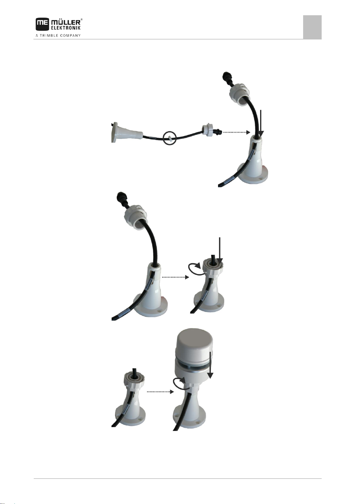
Installation with magnetic base
1.
2.
3.
4.
5.
Page 10

3
Mounting and installation
Installing the Weather Station
10
3030247102-02-EN
6.
7. Identify an appropriate position on the roof of the vehicle. This position must not
be in the slipstream.
8. Use alcohol to clean the position on which you want to mount the Weather
Station.
9. Stick the provided 3M double-sided adhesive tape onto the clean surface.
10. Clean the provided metal plate.
11. Remove the protective paper from the 3M adhesive plate and bond the metal
plate onto this.
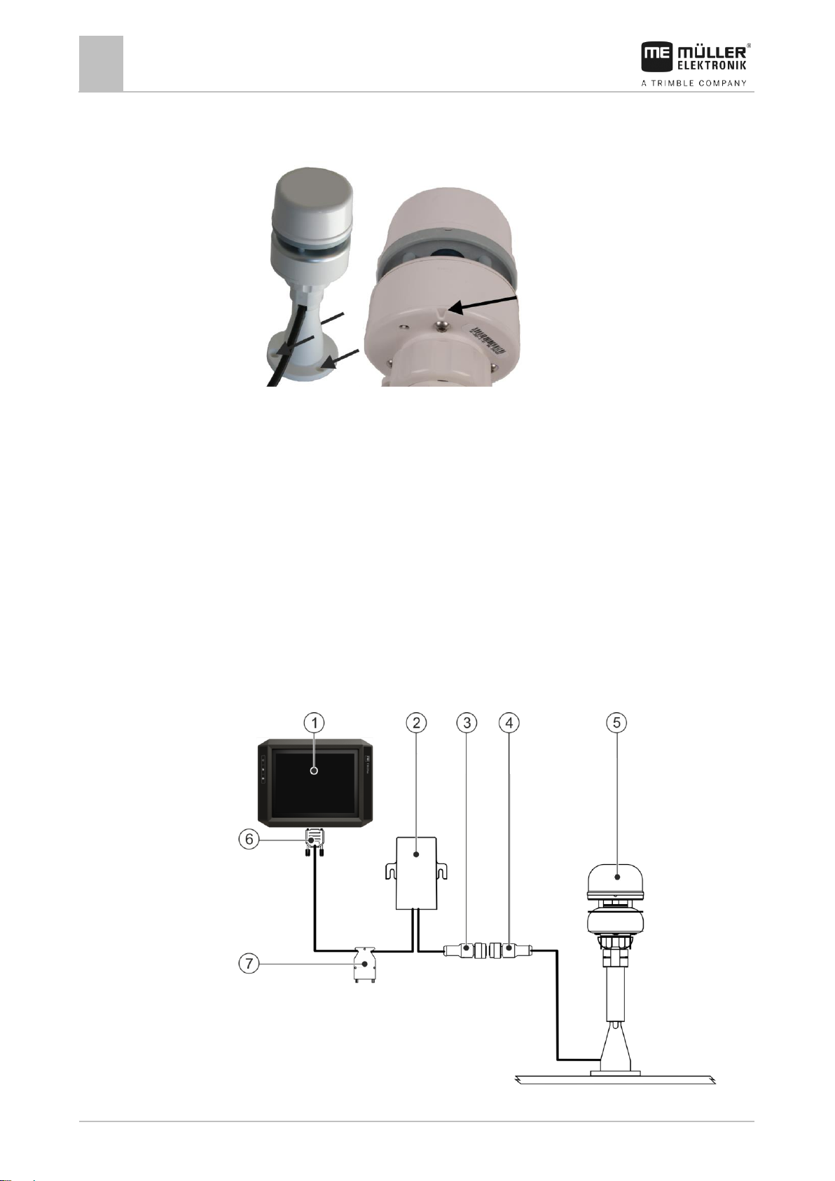
12.
Place the magnetic base and Weather Station onto the metal plate. Ensure that
the Weather Station is firmly secured. The recess must face the direction of
travel.
⇨ You can now connect the Weather Station to a terminal.
Page 11
Mounting and installation
Installing the Weather Station
3
V7.20171121
11
3.1.2
Procedure
Installation with screws
1.
2.
3.
4. Identify an appropriate position on the roof of the vehicle. This position must not
be in the slipstream.
Page 12
3
Mounting and installation
Connecting the Weather Station
12
3030247102-02-EN
3.2
3.2.1
5. Use alcohol to clean the position on which you want to mount the Weather
Station.
6.
Screw the Weather Station firmly onto the roof of the vehicle. Ensure that the
Weather Station is firmly secured. The recess must face the direction of travel.
⇨ You can now connect the Weather Station to a terminal.
Connecting the Weather Station
The Weather Station can be connected in the following ways:
▪ To a terminal. [➙ 12]
▪ To an ISOBUS in-cab-connector. [➙ 14]
▪ With a Deutsch plug to the vehicle's ISOBUS. [➙ 15]
You need different connection cables for each variation.
Connecting the Weather Station to a terminal
Page 13
Mounting and installation
Connecting the Weather Station
3
V7.20171121
13
Terminal
Weather Station
Communication module
CAN connection for the terminal
Connector for communication
module
Connection for the ISOBUS basic
vehicle harness
Weather Station connection
NOTICE
Terminal connector supplying power
Potential damage to the terminal from a short-circuit.
◦ Switch the terminal off before plugging in or removing the connector.
Procedure
You have now installed the Weather Station.
1. Switch off the terminal.
2. Route the cable of the Weather Station into the vehicle cab.
3. Connect the connector from the Weather Station to the connector of the
communication module.
4. Connect connector A of the communication module to the CAN bus socket of the
terminal. For the majority of terminals from Müller-Elektronik this is going to be
the A socket.
5. Connect the connector for the ISOBUS basic vehicle harness to the ISOBUS
basic vehicle harness.
⇨ The Weather Station is now connected between the basic vehicle harness
and the terminal.
⇨ - You can now launch the Weather Station application.
Page 14
3
Mounting and installation
Connecting the Weather Station
14
3030247102-02-EN
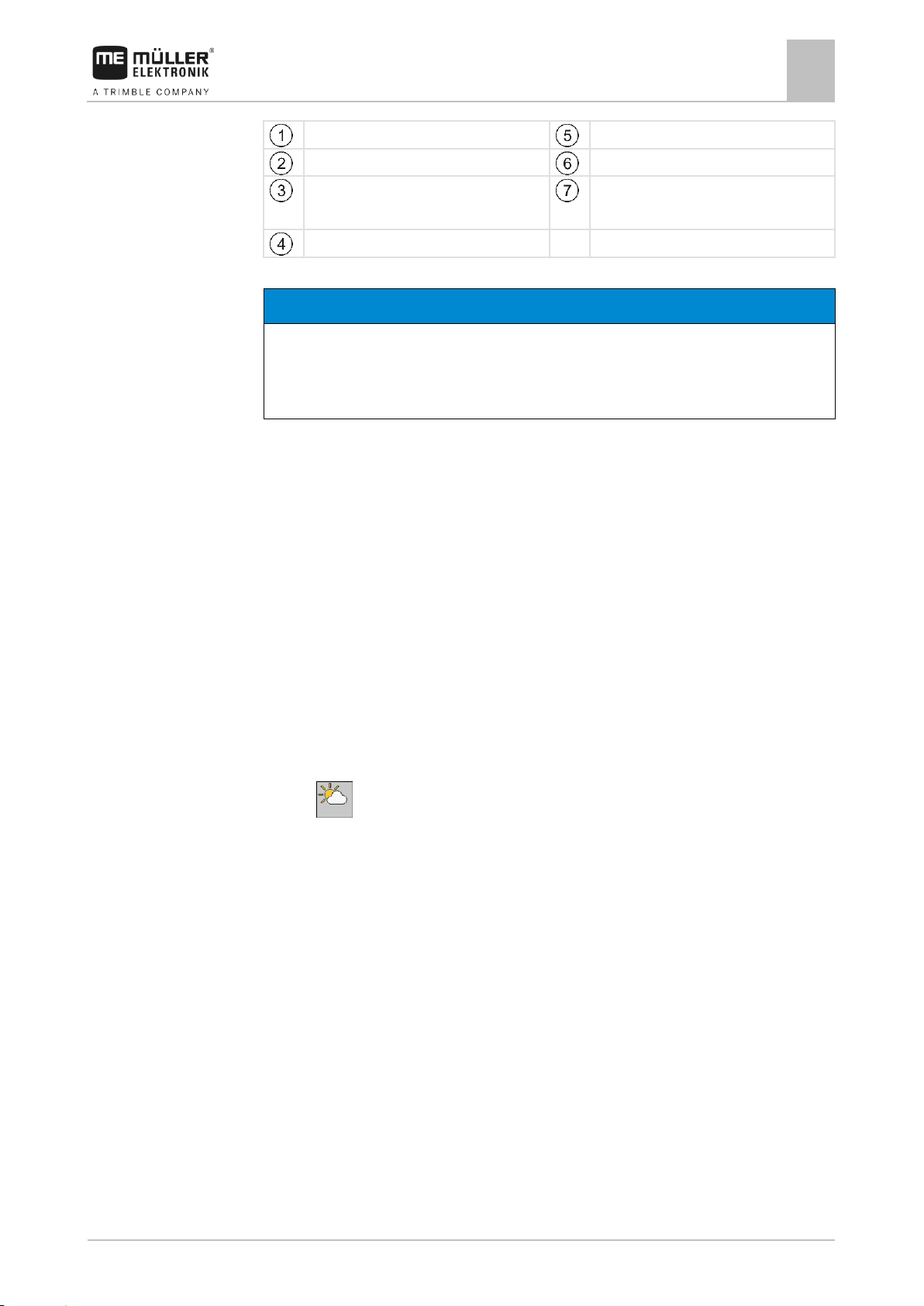
CPC connector for connecting to
the ISOBUS in-cab-connector
Connector for communication
module
Connector for a further ISOBUS
device
Weather Station connection
Communication module
Weather Station
3.2.2
Procedure
Connecting the Weather Station directly to the ISOBUS in-cab-connector
You have now installed the Weather Station.
1. Route the cable of the Weather Station into the vehicle cab.
2. Connect the connector from the Weather Station to the connector of the
communication module.
3. Connect the CPC connector of the communication module to the ISOBUS incab-connector of your vehicle.
4. Optionally, you can also connect a further ISOBUS device using the free
connector. Otherwise, use the supplied termination plug.
⇨ - You can now launch the Weather Station application.
Page 15

Mounting and installation
Connecting the Weather Station
3
V7.20171121
15
Deutsch socket for connection to
the Deutsch plug of the vehicle's
ISOBUS
Connection of the communication
module
Deutsch plug for connection to the
Deutsch socket of the vehicle's
ISOBUS
Connection of the Weather Station
Communication module
Weather Station
3.2.3
Connecting the Weather Station with a Deutsch plug to the vehicle's ISOBUS
You have now installed the Weather Station.
1. Route the cable of the Weather Station into the vehicle cab.
2. Connect the Weather Station to the communication module.
3. Connect the Deutsch plug of the communication module to the Deutsch socket
of the vehicle's ISOBUS.
4. Connect the Deutsch socket of the communication module to the Deutsch plug
of the vehicle's ISOBUS.
⇨ - You can now launch of the Weather Station application.
Page 16
4
Layout of work screen
16
3030247102-02-EN
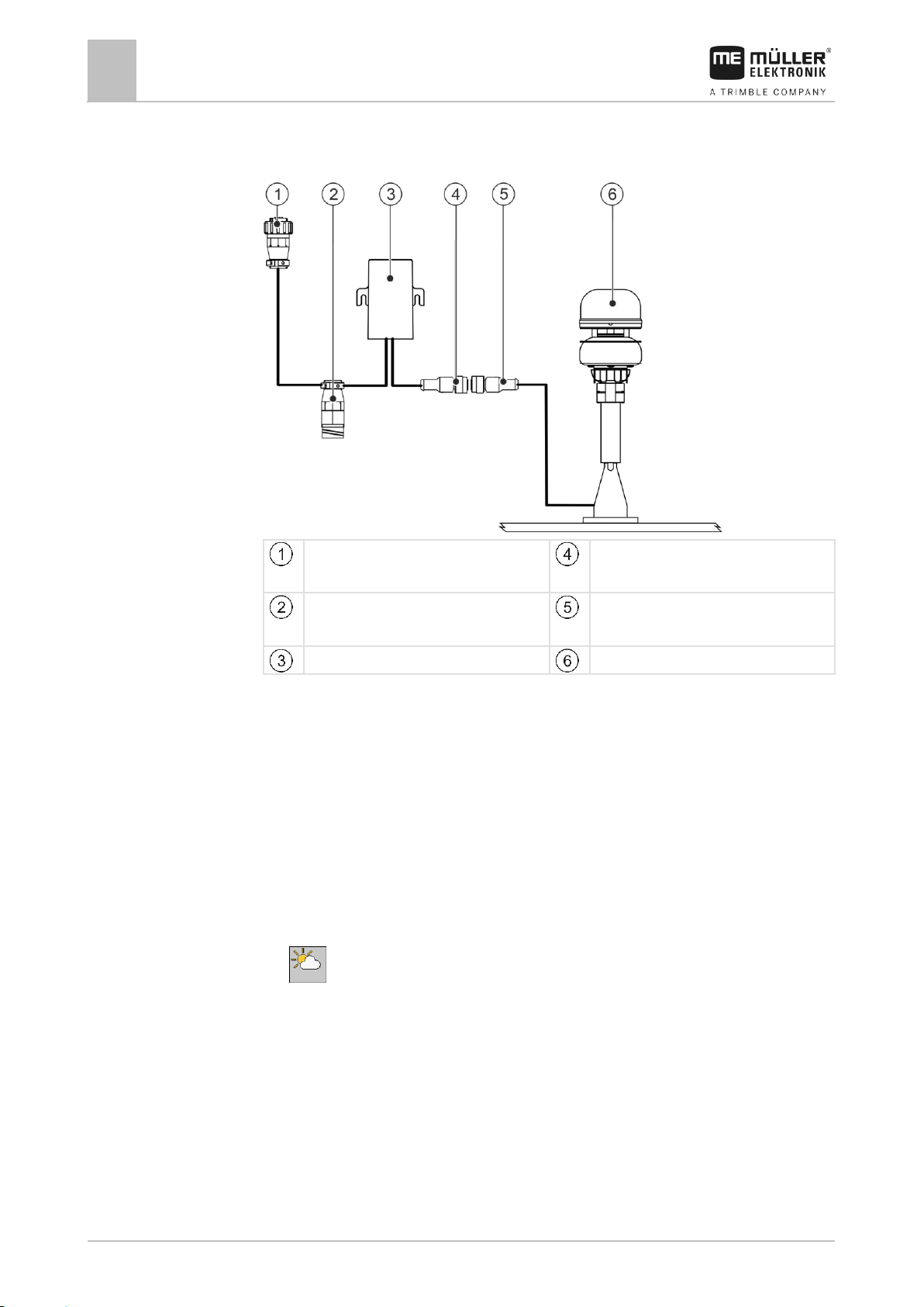
Driving speed
Direction of apparent wind
GPS status
Speed of apparent wind
ISOBUS TC status
Temperature with permissible
range
Speed of true wind
Air pressure with permissible
range
Direction of true wind
Air humidity with permissible range
Gust speed (appears 10 minutes
after switching on)
4
Layout of work screen
You can view directly all of the data determined by the Weather Station on the work
screen:
For a number of values, you can see whether the weather data is within a
permissible range. You can see the permissible range from the colour of the bar
graphs or of the borders of the wind display:
▪ Green: Value is within permissible range.
▪ Red: Value is not within permissible range.
▪ Grey: Value could not be found.
You can configure the permissible range. [➙ 19]
Page 17

Configuration
Calibrating the compass
5
V7.20171121
17
5
5.1
Procedure
5.2
Procedure
Configuration
Calibrating the compass
After installation on any new vehicle, you must calibrate the Weather Station
compass.
1. On the work screen, press:
> >
2. Select "Yes".
3. - Start the compass calibration.
4. Wait until the dot on the screen flashes yellow.
5. Drive circles as large as possible with the vehicle, until the dot on the screen
flashes green. When you want to stop the compass calibration, press: .
⇨ The compass calibration was successful.
6. Repeat the process if the dot flashes red.
Configuring the screen layout
If you are using a Müller-Elektronik terminal, you can configure which weather data
should be displayed in the header, in the additional window and in the main windows
on the display screen.
1. On the work screen, press:
>
2. Select the window for which you want to configure the screen arrangement. You
can choose from the main window, the compass rose in the main window as well
as the header and the additional window.
3. Configure the screen layout. You can see which display corresponds to the
different parts of the screen from the following illustrations.
- Change the screens in the main window.
Page 18

5
Configuration
Configuring the screen layout
18
3030247102-02-EN
Value
Icon
True wind
Apparent wind
Temperature
Air pressure
Air humidity
Roll/Pitch
GPS position
Driving speed
Layout in the main window
Layout of the compass rose in the main window
Layouts in the header
Layouts in the additional window
The following weather data may appear:
Page 19

Configuration
Configuring alarms
5
V7.20171121
19
Value
Icon
Delta T
Dew-point
Drift
Grassland Fire Danger Index
5.3
Procedure
5.4
Procedure
5.5
Procedure
Configuring alarms
You can set measurement values for different weather data for which an alarm is
triggered. See the screen to see which alarms you can set. You can also set a
permissible range. You can see the permissible range in the green area on the bar
graphs on the work screen. [➙ 16]
1. On the work screen, press:
>
2. Configure the alarms.
Configuring the ISOBUS-TC save interval
The time set indicates the number of seconds after which the ISOBUS-TC
application should record the determined weather data.
1. On the work screen, press:
>
2. Configure the parameter
Configuring the filter
You can configure a filter for true and apparent wind.
The average wind speed within the time set is always displayed on the work screen.
The shorter the time, the more accurate the values. Shorter times also mean that
values will often fluctuate.
1. On the work screen, press:
>
2. Configure the "Filter True Wind" and "Filter Appar. Wind" parameters.
Page 20

5
Configuration
Configuring the unit of wind speed
20
3030247102-02-EN
Cured
Colour
Physiological Change
0 %
Green
From the beginning of growth to
commencement of seed head
development.
10 %
Green
Seed heads formed and flowering
5.6
Procedure
5.7
Procedure
5.8
Configuring the unit of wind speed
You can configure in which unit the speed of the true and the apparent wind should
be displayed.
You can choose between:
▪ m/s
▪ km/h
1. On the work screen, press:
>
2. Configure the “Unit Wind Speed” parameter.
Restoring factory settings
You can restore the factory settings at any time. In this case for example, the factory
default values are displayed again on the work screen.
1. On the work screen, press:
2. Select "Yes".
⇨ The Weather Station application will shut down.
3. - You can now launch of the Weather Station application with the factory
settings.
Configuring the grassland fire danger index
The grassland fire danger index describes the fire risk for different plants.
Depending on the appearance and colour of the plants, the fire danger is higher or
lower.
The index is calculated based on a formula that takes account of the dryness of the
plants, wind, temperature and humidity.
The following table shows how to recognise the respective dryness of the plants.
The determined value must then be entered for the "Grass Curing" parameter.
Page 21

Configuration
Configuring the grassland fire danger index
5
V7.20171121
21
Cured
Colour
Physiological Change
20 %
Yellowish-Green
Seeds heads maturing and seed
dropping.
30 %
Yellowish-Green
Most seeds heads mature and seed
dropping.
40 %
Yellow-Green
Most seeds heads mature and seed
dropping.
50-60 %
Straw - odd patch of
green and greenishyellow
Up to 1/2 of all stems have dropped their
seed, some paddocks will be fully cured,
others may be green.
70-80 %
Straw - very little green
showing anywhere
Most seeds heads have dropped their
seed, lower third of stalk may be green.
90 %
Straw - odd green gully
Essentially all seed has dropped, odd
individual stalk may be green.
100 %
Bleached
All stalks fully cured, seed heads and
stalks break easily.
Procedure
Source: National US Weather Service
1. On the work screen, press:
>
2. Configure the "Grass Curing" parameter.
Page 22

6
Technical specifications
Retrieving sensor information
22
3030247102-02-EN
Information
Meaning
Software version
Software version of the communication module
Sensor information
Model ID
Model identification number for the Weather Station.
Software version
Software version of the Weather Station.
Model vers.
Model version of the Weather Station.
Serial no.
Weather Station serial number
Sensor self-test
Was the sensor's self-test successful?
Parameter
Value
Operating voltage
9-16 V
Temperature range
-20°C to +55°C
Power input
<2W
Protection class
IP X6
6
6.1
Procedure
6.2
Technical specifications
Retrieving sensor information
On the "Information" screen, you can retrieve various information on the Weather
Station.
1. On the work screen, press:
The following information is displayed:
Technical data for Weather Station with communication module
Page 23

Technical specifications
Connector pin assignment
6
V7.20171121
23
Pin no.
Signal
Pin no.
Signal
1
CAN_L
6
0VE
2
CAN_L IN
7
CAN_H IN
3
CAN_GND
8
CAN_EN OUT
4
CAN_H
9
+12VE
5
CAN_EN IN
Pin no.
Signal
Pin no.
Signal
1
Relay
6
TBC PWR
(CAN_EN_IN)
2
CAN_L_IN
7
+12VE
3
CAN_L_OUT
8
CAN_GND
4
CAN_H_IN
9
CAN_E
5
CAN_H_OUT
6.3
6.3.1
6.3.2
Connector pin assignment
9-pin Sub-D connector
9-pin CPC connector
Page 24

6
Technical specifications
Connector pin assignment
24
3030247102-02-EN
Pin no.
Signal
Pin no.
Signal
1
VDC
5 2
0V
6
CAN_H
3 7
CAN_L
4 8
Pin no.
Signal
Pin no.
Signal
1
+12VE
3
CAN_H
2
0V
4
CAN_L
Pin no.
Signal
Pin no.
Signal
1
+12VE
3
0V
2
CAN_H_IN
4
CAN_L_IN
6.3.3
6.3.4
6.3.5
8-pin M12 plug
4-pin Deutsch plug for connection to the Weather Station
4-pin Deutsch plug for connection to the vehicle's ISOBUS
Page 25

Technical specifications
Connector pin assignment
6
V7.20171121
25
Pin no.
Signal
Pin no.
Signal
1
+12VE
3
0V
2
CAN_H_OUT
4
CAN_L_OUT
6.3.6
4-pin Deutsch socket for connection to the vehicle's ISOBUS
Page 26
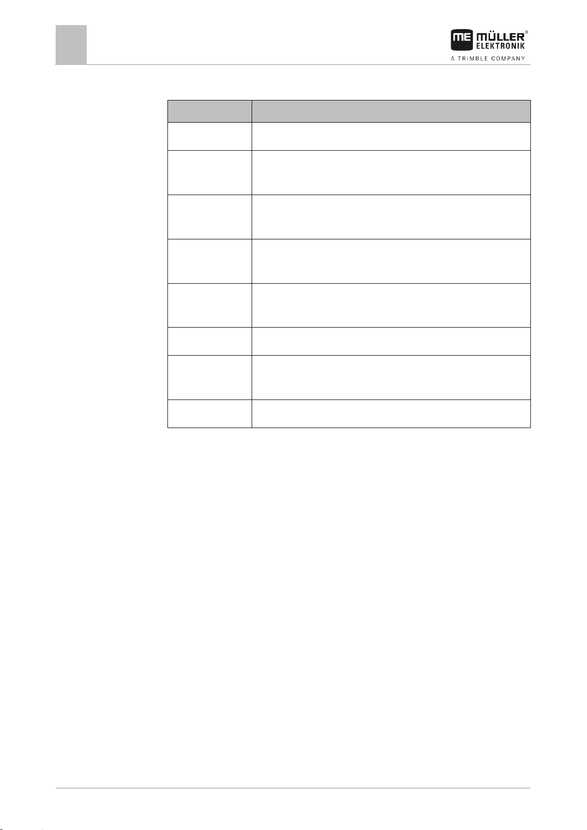
7
Article overview
26
3030247102-02-EN
Item number
Item name
3030247102
Weather Station with bracket but no communication module
3030247105
Weather Station with bracket and communication module with
Sub-D connection cable for Sub-D connection to the terminal
3030247101
Communication module with Sub-D connection cable for Sub-D
connection to the terminal
3030247103
Communication module with CPC connection cable for
ISOBUS in-cab-connector
3030247104
Weather Station with bracket and communication module with
CPC connection cable for ISOBUS in-cab-connector
3030247107
Weather Station with bracket but no communication module
3030247106
Communication module with Deutsch connection cable for the
vehicle's ISOBUS
31300582
Termination plug for the CPC connection cable
7
Article overview
 Loading...