

Page 1
Installation and operating instructions
TRACK-Guide III
Version: V5.20170221
31302713-02-EN
Read and follow these operating instructions.
Keep these operating instructions in a safe place for later
reference.
Page 2

Document
Copyright ©
Company details
Installation and operating instructions
Product: TRACK-Guide III
Document number: 31302713-02-EN
As of software version: V02.15.12
Original language: German
Müller-Elektronik GmbH & Co.KG
Franz-Kleine-Straße 18
33154 Salzkotten
Germany
Phone: ++49 (0) 5258 / 9834 - 0
Fax: ++49 (0) 5258 / 9834 - 90
Email: info@mueller-elektronik.de
Homepage: http://www.mueller-elektronik.de
Page 3

Table of contents
31302713-02-EN
V5.20170221
3
1
For your safety
7
1.1
Basic safety instructions
7
1.2
Intended use
7
1.3
Layout and meaning of warnings
8
1.4
Disposal
8
1.5
Instructions on retrofitting
8
2
About these Operating Instructions
10
2.1
Target group of these Operating Instructions
10
2.2
Layout of operating instructions
10
2.3
Layout of references
10
2.4
Directional information in these instructions
10
2.5
Current version
10
3
Product description
11
3.1
Scope of delivery
11
3.2
Terminal buttons
11
3.3
Terminal ports
11
3.4
Applications on the terminal
12
3.5
Information on the nameplate
14
3.6
EC declaration of conformity
14
4
Mounting and installation
15
4.1
Mounting the terminal in the vehicle cab
15
4.1.1
Mounting the standard bracket
15
4.1.2
Mounting the optional bracket
16
4.1.3
Mounting the optional adaptor
16
4.2
Connecting the terminal to voltage supply
17
4.3
Connecting the terminal to the ISOBUS
17
4.4
Inserting a Micro-SD card
18
4.5
Using two terminals
18
5
Basic control principles
20
5.1
Switching on the terminal
20
5.2
Initial start-up
20
5.2.1
Using the terminal for parallel guidance
20
5.2.2
Operating an ISOBUS implement
21
5.2.3
Terminal for automatic section control
21
5.2.4
Terminal for task processing
22
5.3
Switching off the terminal
23
5.4
Terminal screen layout
23
5.5
Opening applications
24
Table of contents
Page 4

Table of contents
4
V5.20170221
31302713-02-EN
5.6
Moving an application
25
5.7
Saving and loading window arrangements
25
5.8
Hiding an application
26
5.9
Using the keyboard
26
5.10
Using a memory device
27
5.10.1
Using a SD card
27
5.10.2
Folders on the USB memory device
27
5.10.3
Displaying the content of the memory device on the terminal
28
6
Connecting and configuring external devices
29
6.1
GPS receiver
29
6.1.1
Connecting the GPS receiver to the terminal
29
6.1.2
Changing the driver for the GPS receiver
29
6.1.3
Configuring the GPS receiver
31
Parameters for the GPS receiver
31 RTK or L band licence for SMART-6L
34
GSM modem for SMART-6L
34
Configuring the GPS receiver for the steering system
35
6.1.4
Recording GPS positions
36
6.1.5
Configuring the "GPS TILT-Module" terrain compensation
37
6.2
Configuring the joystick button allocations
37
6.3
Connecting sensors to the terminal
38
6.4
Camera
39
6.4.1
Connecting the camera to the terminal
39
Connecting the camera HQ2
39
Connecting the camera NQ
40
6.4.2
Activating a camera
40
6.4.3
Operating the camera
41
6.5
External lightbar
41
6.5.1
Connecting the external lightbar to the terminal
41
6.5.2
Activating an external LightBar
42
6.6
Connecting the on-board integrated display/controller to the terminal
42
6.7
ISO printer
43
6.7.1
Connecting the ISO printer to the terminal
43
6.7.2
Activating the ISO printer
44
6.8
Configuring the Bluetooth connection in the Connection Center
44
6.9
Crop protection sensors
44
7
Configuring the terminal in the Service application
46
7.1
Changing the language
46
7.2
Basic settings
46
7.3
Enabling and disabling applications
48
7.4
Unlocking licenses for full versions
49
7.5
Creating screenshots
50
7.6
Deleting pools
50
Page 5

Table of contents
31302713-02-EN
V5.20170221
5
8
Tractor-ECU application
51
8.1
Work screen
51
8.2
Managing the tractor profiles
51
8.3
Parameters
53
8.3.1
Calibrating the speed sensor
55
8.3.2
Calibrating an analog working position sensor
56
8.3.3
Tractor geometry
56
8.4
Results
57
8.4.1
Trip counter
57
8.4.2
Task-related counter
58
9
Virtual ECU application
59
9.1
Managing virtual job computers
59
9.2
Parameters
60
9.3
Work screen
62
10
ISOBUS-TC task processing
63
10.1
Configuring ISOBUS-TC
63
10.1.1
The "farmpilot" parameter
63
10.1.2
“Operating Mode” parameter
63
10.1.3
“TC number” parameter
64
10.1.4
“Prefer internal Tractor-ECU?” parameter
64
10.1.5
"Save finished tasks as a file?" parameter
65
10.1.6
“Validation of the device description” parameter
65
10.2
Configuring the list of connections
65
10.3
Using fields and shp data
66
10.3.1
What is field data for?
67
10.3.2
Creating fields
67
10.3.3
Activating and deactivating fields
68
10.3.4
Importing field data (*.shp)
69
10.3.5
Exporting field data
70
10.3.6
Data on the memory device
70
10.3.7
Transferring field data to a different terminal
70
10.4
Using prescription maps
71
10.4.1
Importing shape prescription maps
71
10.4.2
Selecting shape prescription maps
72
10.4.3
Editing shape prescription maps
72
10.4.4
ISO-XML prescription maps
73
10.5
MULTI-Control
73
11
File Server application
75
12
Technical specifications
76
12.1
Technical specifications of the terminal
76
12.2
Assignment plans
77
12.2.1
Port A (CAN bus)
77
12.2.2
Port B
77
Page 6

Table of contents
6
V5.20170221
31302713-02-EN
12.2.3
Port C
78
12.2.4
CAM port
79
12.2.5
ETH (Ethernet) port
80
12.3
Licence conditions
80
13
History
81
13.1
V5.20170221
81
Page 7
For your safety
Basic safety instructions
1
31302713-02-EN
V5.20170221
7
1
1.1
1.2
For your safety
Basic safety instructions
Please read the following safety instructions carefully before using the product for the first time.
▪ Do not operate the terminal while driving in road traffic. Come to a standstill in order to use the
unit.
▪ Before maintaining or repairing the tractor, always disconnect the connection between the tractor
and the terminal.
▪ Before charging the tractor battery, always disconnect the connection between the tractor and
the terminal.
▪ Before welding on the tractor or implement, always disconnect the power supply to the terminal.
▪ Do not make any unauthorized modifications to the product. Unauthorized modifications or use
may impair safety and reduce the service life or operability of the unit. Modifications are
considered unauthorized if they are not described in the product documentation.
▪ Follow all recognized safety, industrial and medical rules as well as all road traffic laws.
▪ The product does not include any user-serviceable parts. Do not open the casing. If the casing is
opened, its imperviousness can be changed.
▪ Read the operating instructions to the agricultural device which you want to control by using the
product.
Using a camera
The camera serves solely for observing the implement functions in non-safety-related working areas
of the agricultural implement.
In certain situations, the camera image may appear on the screen with a delay. The delay depends
on the respective use of the terminal and can also be affected by external factors and devices.
For this reason, please note the following information:
▪ Do not use the camera to assist with steering the vehicle: not in road traffic, and not on private
properties.
▪ Do not use the camera to watch the road traffic or when driving into intersections.
▪ Do not use the camera as a rear view camera.
▪ Do not use the camera as a visual aid for controlling the implement, especially when a delayed
reaction can lead to risks.
▪ Using a camera does not exempt you from your due diligence obligation to pay attention to
safety when operating the implement.
Intended use
The terminal is used to operate agricultural machinery equipped with ISOBUS job computers.
Intended use also includes compliance with the conditions for operation and repairs prescribed by the
manufacturer.
The manufacturer cannot be held liable for any personal injury or property damage resulting from
such non-compliance. All risk arising from improper use lies with the user.
All applicable accident prevention regulations and all other generally recognized safety, industrial,
and medical standards as well as all road traffic laws must be observed. Any unauthorized
modifications made to the equipment will void the manufacturer's warranty.
Page 8
1
For your safety
Layout and meaning of warnings
8
V5.20170221
31302713-02-EN
WARNING
This signal word identifies medium-risk hazards, which could potentially cause death or serious
physical injury, if not avoided.
CAUTION
This signal word identifies hazards that could potentially cause minor or moderate physical injury or
damage to property, if not avoided.
NOTICE
This signal word identifies hazards that could potentially cause damage to property, if not avoided.
When it has reached the end of its service life, please dispose of this product as
electronic scrap in accordance with all applicable waste management laws.
1.3
Example
1.4
1.5
Selecting components
Layout and meaning of warnings
All safety instructions found in these Operating Instructions are composed in accordance with the
following pattern:
There are some actions that need to be performed in several steps. If there is a risk involved in
carrying out any of these steps, a safety warning will appear in the instructions themselves.
Safety instructions always directly precede the step involving risk and can be identified by their bold
font type and a signal word.
1. NOTICE! This is a notice.It warns that there is a risk involved in the next step.
2. Step involving risk.
Disposal
Instructions on retrofitting
Instructions on how to retrofit electrical and electronic farm equipment and/or
components
Agricultural equipment used today features electronic components and parts whose function can be
affected by other farm equipment which emits electromagnetic waves. Such effects could lead to
personnel being put in danger, if the following safety instructions are not adhered to.
When selecting components, make sure first of all that the retrofitted electrical and electronic
components comply with the current version of the EMC Directive 2004/108/EC and carry the CE
marking.
Page 9

For your safety
Instructions on retrofitting
1
31302713-02-EN
V5.20170221
9
User responsibility
Additional requirements
When retrofitting a machine with electrical and electronic farm equipment and/or components
connected to the vehicle's electrical system, it is your own responsibility to check whether the
installation causes interference with the vehicle's electronic system or other components. This
applies, in particular, to the electronic control of:
▪ electronic hitch control (EHR),
▪ front linkage,
▪ power take off (PTO),
▪ engine,
▪ gear.
The following requirements must be met in order to retrofit mobile communication systems (e.g. radio,
phone):
▪ All farm equipment must be approved and installed in accordance with the regulations applicable
in the respective country.
▪ The equipment must be installed as a fixed installation.
▪ The operation of portable or mobile farm equipment in the interior of the vehicle is only permitted
via a connection to a permanently installed exterior antenna.
▪ The transmitting part must be spatially separated from the vehicle's electronic system.
▪ When attaching the antenna, pay attention to proper installation, including a sound ground
connection between the antenna and the vehicle's ground wire.
For information on wiring and installation as well as the maximum allowable current consumption,
please also refer to the installation guide provided by the machine manufacturer.
Page 10
2
About these Operating Instructions
Target group of these Operating Instructions
10
V5.20170221
31302713-02-EN
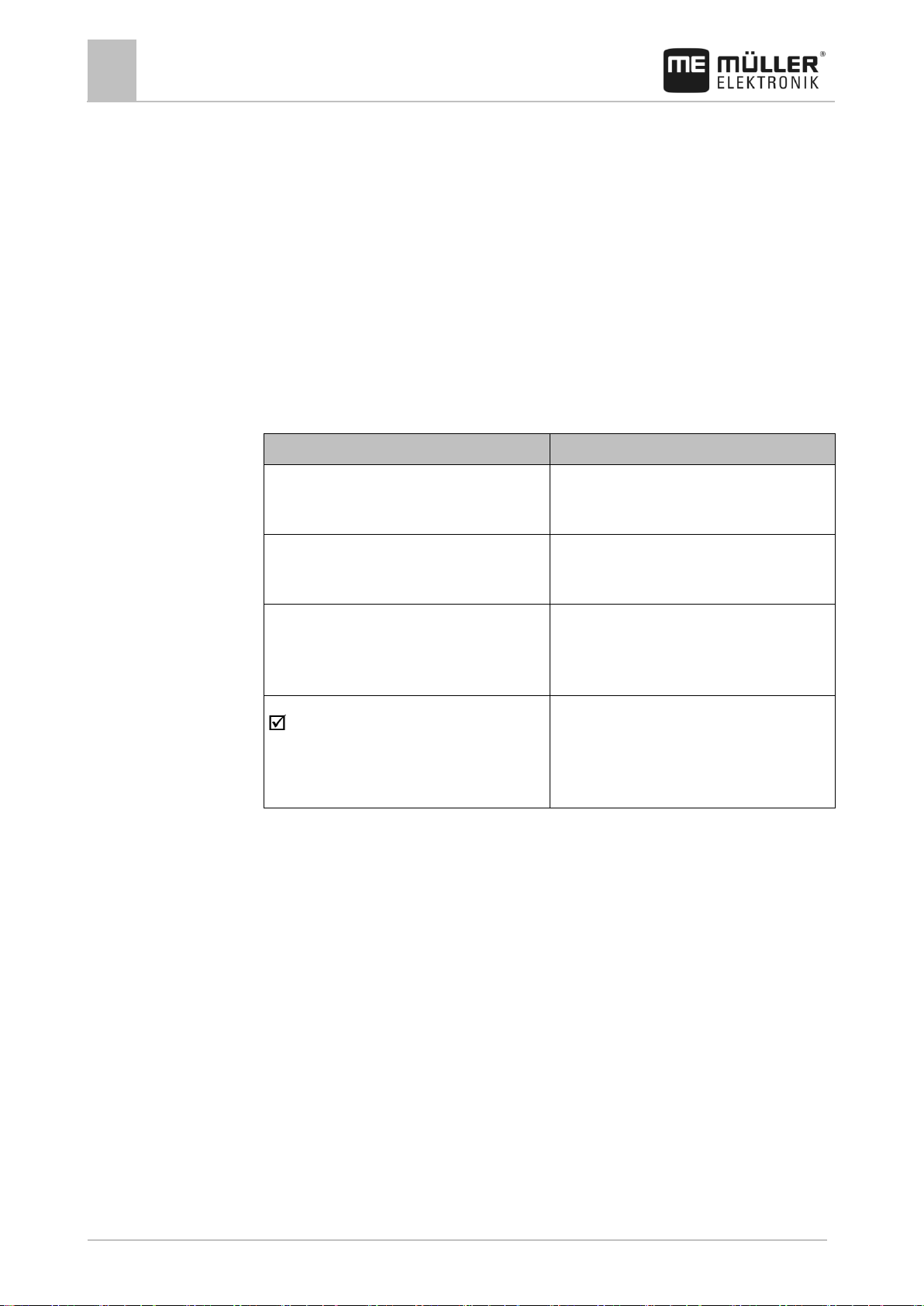
Type of depiction
Meaning
1.
2.
Actions that must be performed in succession.
⇨
Result of the action.
This will happen when you perform an action.
⇨
Result of an operating instruction.
This will happen when you have completed all
steps.
Requirements.
In the event that any requirements have been
specified, these must be met before an action
can be performed.
2
2.1
2.2
2.3
2.4
2.5
About these Operating Instructions
Target group of these Operating Instructions
These Operating Instructions are intended for personnel entrusted with installing and operating the
terminal.
Layout of operating instructions
The operating instructions explain step by step how you can perform certain operations with the
product.
We use the following symbols throughout these Operating Instructions to identify different operating
instructions:
Layout of references
If any references are given in these Operating Instructions, they will appear as:
Example of a reference: [➙ 10]
References can be identified by their square brackets and an arrow. The number following the arrow
shows you on what page the section starts where you can find further information.
Directional information in these instructions
All directional information in these instructions, such as "left", "right", "forward", "back", is relative to
the movement direction of the vehicle.
Current version
The current version of these instructions can be found on our website: www.mueller-elektronik.de.
Page 11
Product description
Scope of delivery
3
31302713-02-EN
V5.20170221
11
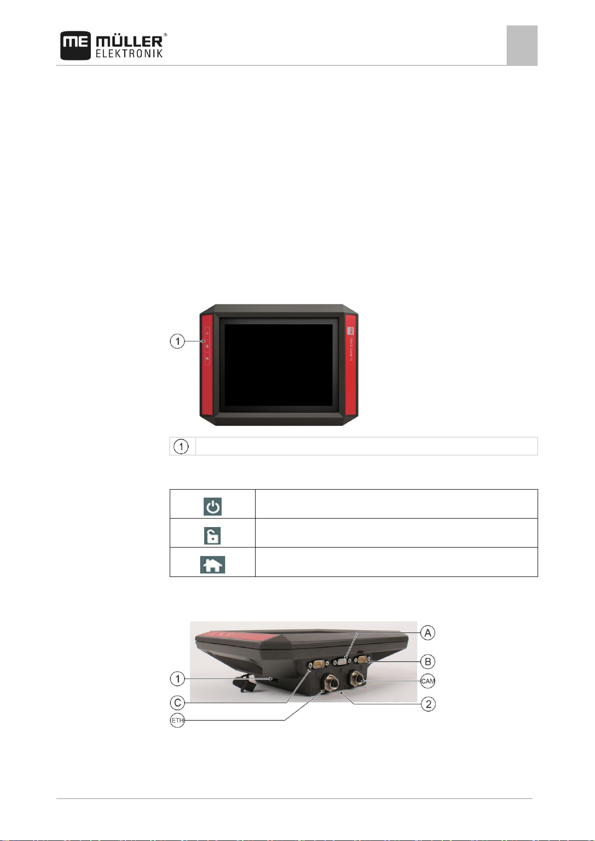
Terminal buttons
Switches the terminal on and off.
Creates screenshots.
Saves the window layout.
3
3.1
3.2
3.3
Product description
Scope of delivery
The following items are included in delivery:
▪ TRACK-Guide III terminal
▪ VESA holder and screws
▪ Bracket for mounting the terminal
▪ USB memory device
▪ Installation and Operating Instructions
▪ Operating instructions for the TRACK-Leader application - as a separate document.
Terminal buttons
You will find a number of buttons on the housing of the terminal that are used to operate the terminal.
Function of the buttons
Terminal ports
Terminal ports
Page 12
3
Product description
Applications on the terminal
12
V5.20170221
31302713-02-EN
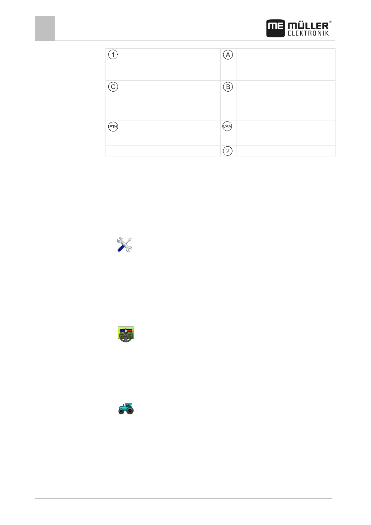
USB port for:
- USB memory device [➙ 27]
Port A
CAN bus port for:
- ISOBUS basic vehicle harness [➙ 17]
- Connection to the tractor CAN bus
Port C
Serial port for:
- GPS receiver [➙ 29]
- GPS TILT-Module
- Lightbar [➙ 41]
Port B
See section: Pin assignment Port B [➙ 77]
ETH port
M12 port for:
- Ethernet
CAM port
Port for an analog camera
Slot with the SD card
3.4
Full versions
Applications on the terminal
The terminal is delivered with a range of installed application (apps). Most of these can be used
immediately. Even the non-activated applications can generally be tested for 50 hours. If a specific
application works well for you, a license can be ordered from Müller-Elektronik to activate the full
version of the application.
The full versions of the following applications are installed on the terminal:
▪ - Service application.
The Service application allows you to:
– Configure the terminal.
– Enable and disable other applications.
– Enter license activation codes.
– Enable drivers for connected devices.
– Configure the GPS settings.
▪ - TRACK-Leader application.
The TRACK-Leader application allows you to work the field on exact parallel tracks.
The app contains several modules for which a license can also be activated:
– SECTION-Control: Automatic section control in order to minimize overlaps.
– TRACK-Leader AUTO: Automatic vehicle steering on the field.
– TRACK-Leader TOP: Automatic vehicle steering on the field.
▪ - Tractor-ECU application
The Tractor-ECU application is used to record all settings around the tractor.
Here, you can e.g.:
– Enter the position of the GPS receiver.
– Set the GPS receiver as the speed signal source.
– Select which sensor signals are received by the terminal.
– View the speed and PTO shaft rotational speed on the screen.
Page 13
Product description
Applications on the terminal
3
31302713-02-EN
V5.20170221
13
Test versions
Optional software
More about this in section: Tractor-ECU application [➙ 51]
▪ - Virtual ECU application
The Virtual ECU application is a central hub where virtual job computers can be created for
machines and devices that do not communicate through ISOBUS.
The Virtual ECU enables the use of apps such as TRACK-Leader, ISOBUS-TC and SECTION-
Control with non-ISO machines.
More about this in section: Virtual ECU application [➙ 59]
▪ File Server application
This application is used to define a storage location on the terminal. This storage location can be
used by ISOBUS job computers that support the File Server functionality. The options for use
depend on the ISOBUS job computer.
▪ - Camera.
The Camera application displays on the screen the image from the camera which is connected
to the terminal.
▪ ME ODI
The application is used to connect the terminal with the Internet via Ethernet or Bluetooth.
You can use the test versions of the following applications:
▪ ISOBUS interface (ISOBUS-UT)
The terminal enables you to operate ISOBUS job computers which are ISO 11783 compliant.
The user interfaces for operating a job computer are shown on the terminal screen if this is
connected to the ISOBUS connector of the vehicle.
The ISOBUS interface has no icon of its own. The icon for the connected job computer will
always be displayed in the selection menu.
▪ - ISOBUS-TC application (ISOBUS task controller)
The ISOBUS-TC application serves as an interface between the terminal applications
(SECTION-Control, TECU, VECU) and ISOBUS devices (job computers, crop protection
sensors). Moreover, the app enables data transfer between the terminal and electronic Farm
Management Information Systems.
The scope of functions depends on the activated licenses and the configuration.
More about this in section: ISOBUS-TC task processing [➙ 63]
▪ ME ODI
The application is used to connect the terminal with the Internet via Ethernet or Bluetooth.
▪ ASD protocol – The license enables communication between the terminal and a serially
connected on-board integrated display/controller. The terminal knows the position of the machine
on the field (GPS) and can transmit the target application rate of a product (from the prescription
map) or the section status to the on-board integrated display/controller. In this way, you can use
the SECTION-Control app for section control, among other things.
More about this in section: Connecting the on-board integrated display/controller to the terminal [
➙ 42]
Optionally you can activate the following software:
▪ - FIELD-Nav application.
FIELD-Nav – Road navigation for agricultural purposes. The map material can be edited with the
corresponding PC software FIELD-Nav Desktop. All field tracks, small bridges and other
restrictions can then be integrated in the map material and be considered when mapping the
route.
Page 14
3
Product description
Information on the nameplate
14
V5.20170221
31302713-02-EN
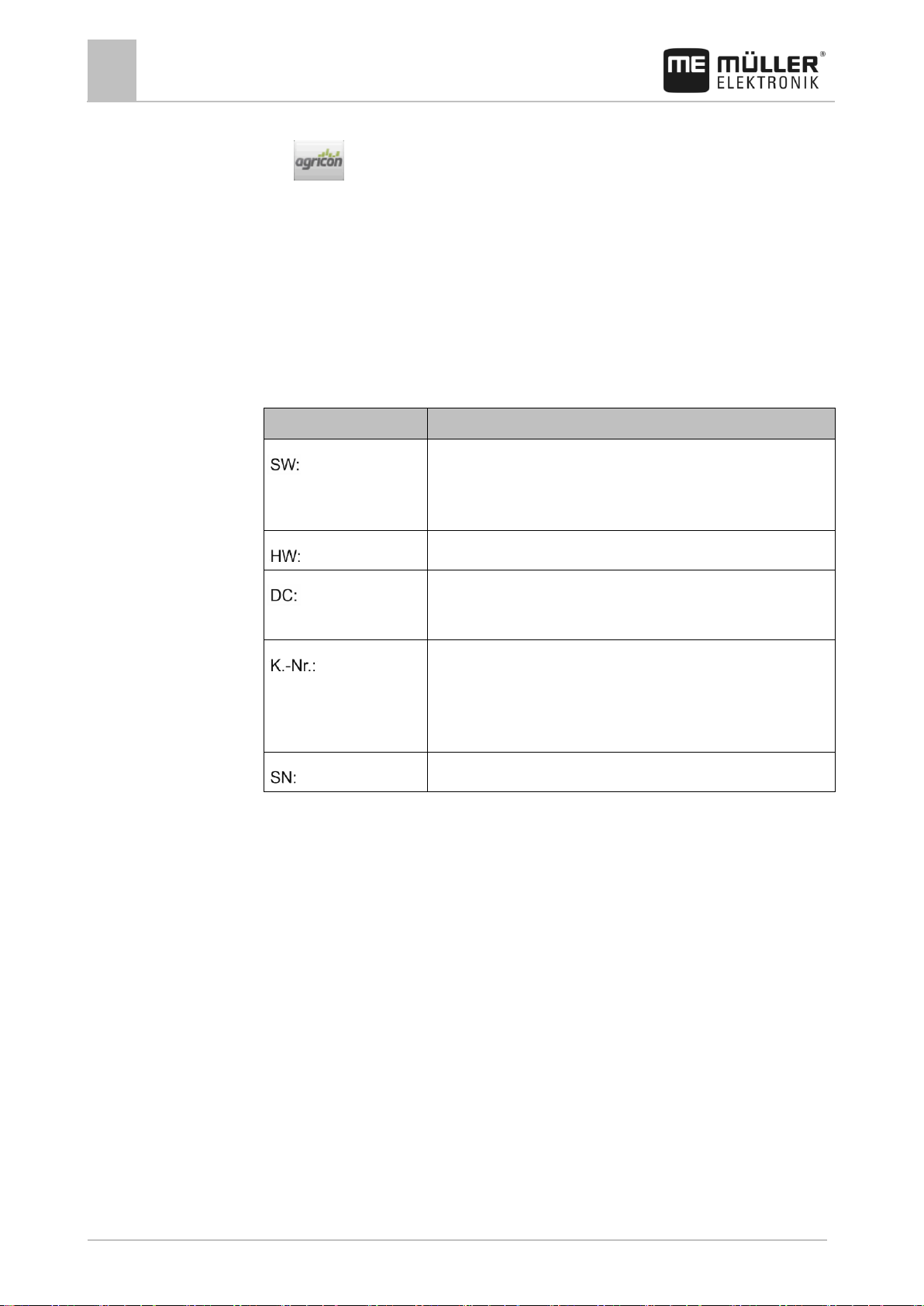
Abbreviation
Meaning
Software version
You can see the installed software version on the Start Screen of the
Service application:
Hardware version
Operating voltage
The terminal may only be connected to voltages within this range.
Customer number
If the terminal was manufactured for an agricultural machinery
manufacturer, the agricultural machinery manufacturer's item number
will be shown here.
Serial number
3.5
3.6
You will find the operating instructions on the Müller-Elektronik website.
▪ - Agricon plugin
Enables coupling with crop protection sensors (Yara-N, P3US, P3ALS etc.) manufactured by
Agricon.
Information on the nameplate
You will find a nameplate sticker on the back of the terminal. On this sticker, you can find all the
information you need to definitively identify the product.
Have these details ready when you contact Customer Services.
Abbreviations on the rating plate
EC declaration of conformity
This product is manufactured in conformity with EMC Directive 2004/108/EC using the following
harmonized standards:
▪ EN ISO 14982
Page 15

Mounting and installation
Mounting the terminal in the vehicle cab
4
31302713-02-EN
V5.20170221
15
Item number
Type
Scope of
delivery?
Properties
31322506
Standard bracket
Yes
31322507
Optional bracket
No
▪ For a more sturdy attachment of the
terminal.
31322508
Optional adaptor
No
▪ Is mounted on bracket 31322507.
▪ Suitable for vehicles without a B
column.
▪ Is mounted around a pipe.
4
4.1
4.1.1
Procedure
Mounting and installation
Mounting the terminal in the vehicle cab
You need a bracket to mount the terminal in the vehicle cab. The following brackets are available.
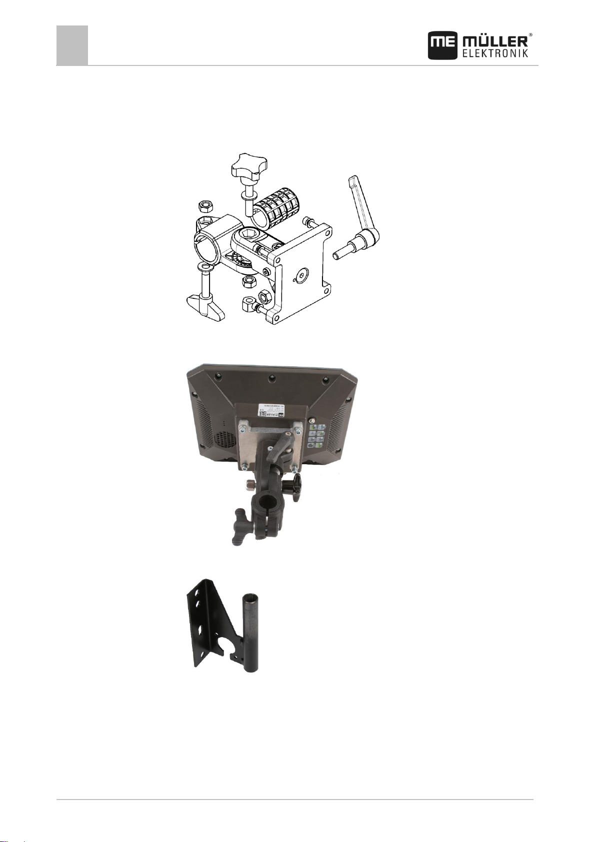
Mounting the standard bracket
You have the VESA bracket assembly kit within reach.
1. Assemble the bracket together.
2. Secure the bracket with the four screws on the back side of the terminal.
3. Secure the terminal in the vehicle cab. You can, for example, use the ME mounting bracket for
this purpose. It is included in the scope of delivery of the ISOBUS basic equipment.
⇨ Your terminal should be mounted as follows:
4. Check that your terminal is firmly mounted.
⇨ You can now connect cables to the terminal. [➙ 11]
Page 16
4
Mounting and installation
Mounting the terminal in the vehicle cab
16
V5.20170221
31302713-02-EN
4.1.2
Procedure
4.1.3
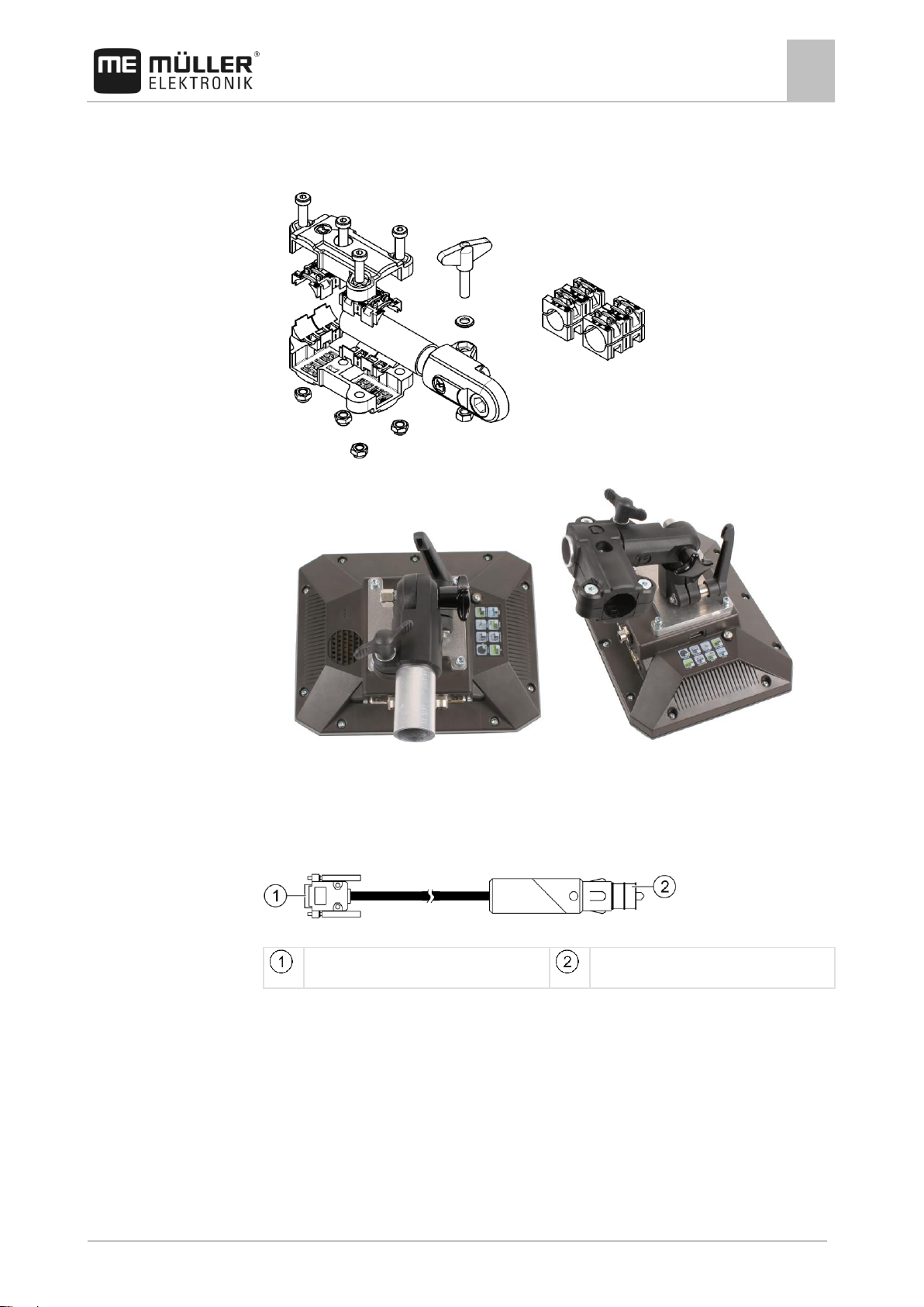
Mounting the optional bracket
You have the bracket assembly kit within reach.
1. Assemble the bracket together.
2. Secure the bracket with the four screws on the back side of the terminal.
3. Put the bracket into the desired position. See below:
4. Secure the terminal in the vehicle cab. You can, for example, use the ME mounting bracket for
this purpose. It is included in the scope of delivery of the ISOBUS basic equipment.
5. Check that your terminal is firmly mounted.
Mounting the optional adaptor
If you want to mount your terminal in a vehicle that does not have a B column, you can install an
adaptor onto bracket 31322507. This adaptor can be mounted around a pipe.
Page 17
Mounting and installation
Connecting the terminal to voltage supply
4
31302713-02-EN
V5.20170221
17
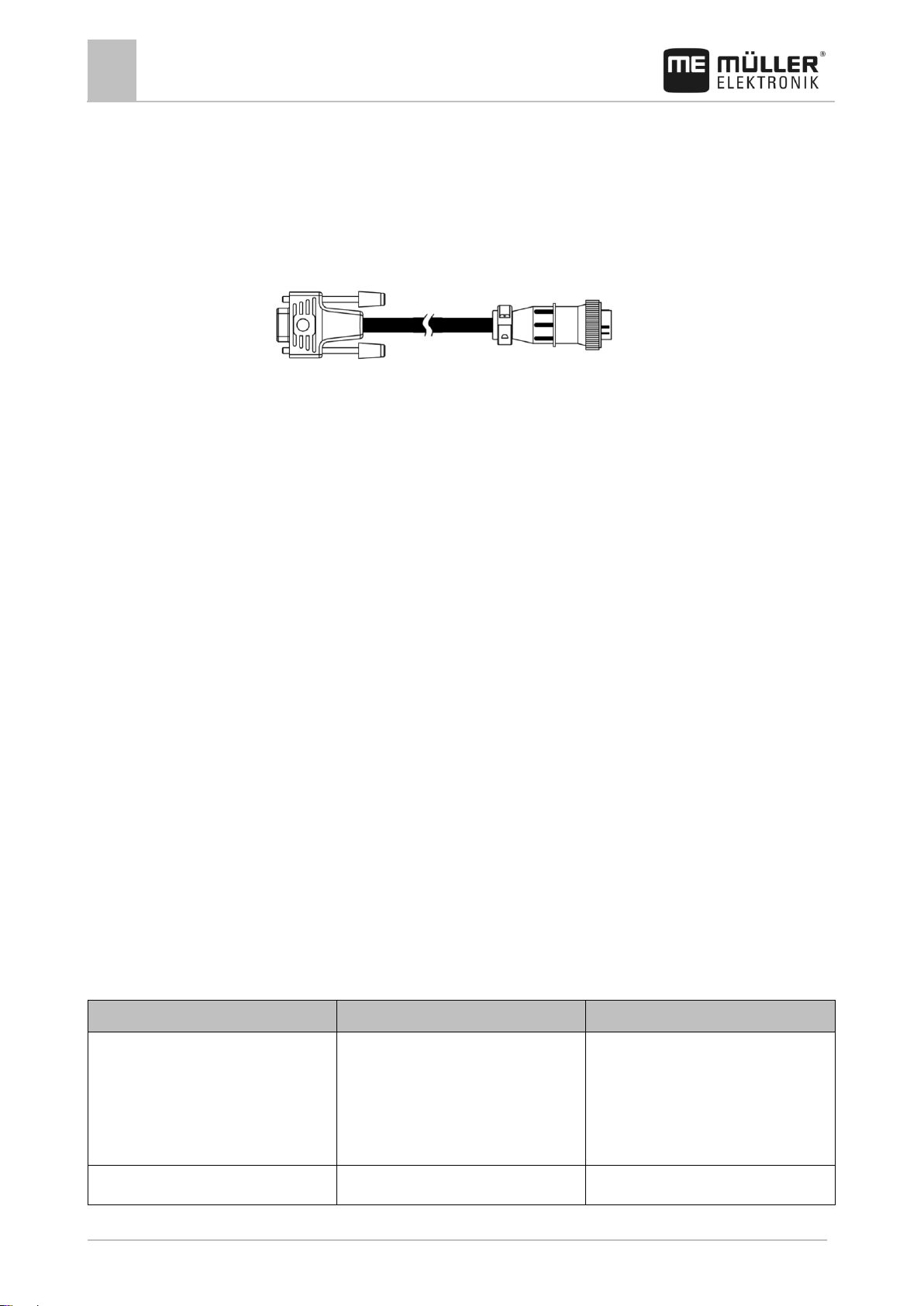
9-pin Sub-D on socket A in the terminal
Plug for vehicle power supply (cigarette
lighter)
Procedure
4.2
Procedure
4.3
▪ Adaptor for round pipe systems, for pipes with a diameter of 20, 25 or 30 mm, item number:
31322508
1. Assemble the adaptor together.
2. Connect the adaptor with the bracket.
3. Put the bracket and the adaptor in the desired position.
4. Check that everything is firmly mounted.
Connecting the terminal to voltage supply
Cable for the power supply - Item no. 31302495
This is how you connect the terminal to voltage supply:
1. Connect the power cable included in the delivery to port A of the terminal.
2. Connect the power cable on the other side to (10V - 30V) the vehicle's electrical system.
Connecting the terminal to the ISOBUS
Connection to the ISOBUS serves to:
▪ supply the terminal with power,
Page 18
4
Mounting and installation
Inserting a Micro-SD card
18
V5.20170221
31302713-02-EN
Possible purpose
TRACK-Guide settings
Setting of the in-cab terminal
TRACK-Leader and SECTION-Control on
the ME terminal.
Operation of the job computer on the incab terminal.
Login as ISOBUS terminal: No [➙ 46]
Activate the ISOBUS terminal (JohnDeere:
Implement Bus; Fendt: Fendt ISOBUS
terminal).
Deactivate Task Controller (JohnDeere:
Task Controller; Fendt: Taskcontroller).
TRACK-Leader, SECTION-Control, and
Login as ISOBUS terminal: Yes [➙ 46]
Deactivate the ISOBUS terminal
Procedure
4.4
Procedure
4.5
▪ enable communication with other ISOBUS components.
You will need a different connection cable for this, depending on the model of your tractor.
▪ In tractors that have been retroactively upgraded with an ISOBUS basic vehicle harness
manufactured by Müller-Elektronik, use connector cable A from the ISOBUS basic vehicle
harness.
▪ In tractors that are equipped as standard with ISOBUS and that have an ISOBUS in-cab
connector, you will need the following connector cable:
Sub-D <-> CPC connector cable, item no. 30322541
When there is more than one terminal in the tractor cab, you may need to change certain settings in
order to enable two-way communication. Find out more: Using two terminals [➙ 18]
1. Connect the 9-pin plug A of the basic vehicle harness to the CAN port of the terminal.
2. Tighten the safety screws on the connector.
Inserting a Micro-SD card
The micro-SD card serves as internal storage for the terminal.
To change the SD card:
1. Switch off the terminal and disconnect all cable connections.
2. Unscrew the cover on the rear of the terminal.
3. Use your finger to press on the SD card in the slot.
⇨ The SD card is unlocked and now protrudes by approx. 1 mm.
4. You can remove the card.
5. To lock the card again, press the card lightly into the slot until it is locked again.
6. Screw the cover back onto the rear of the terminal.
Using two terminals
The following table will tell you which settings you need to configure to be able to use two terminals,
and the chapters in which these are described. The specifications on the in-cab terminals are without
liability.
Settings for TRACK-Guide and the in-cab terminal
Page 19

Mounting and installation
Using two terminals
4
31302713-02-EN
V5.20170221
19
Possible purpose
TRACK-Guide settings
Setting of the in-cab terminal
job computer operation on the ME
terminal.
The ISOBUS terminal licence is required.
(JohnDeere: Implement Bus; Fendt: Fendt
ISOBUS terminal).
Deactivate Task Controller (JohnDeere:
Task Controller; Fendt: Taskcontroller).
For JohnDeere, also deactivate:
Greenstar, Original GreenStar Monitor
Page 20
5
Basic control principles
Switching on the terminal
20
V5.20170221
31302713-02-EN
Setting
Where?
Purpose
Select the GPS driver.
/ Driver / GPS [➙ 29]
The standard driver works in
most cases for the receivers
sold by ME. However, to
change the correction signal, a
fitting driver for the GPS
5
5.1
Procedure
5.2
5.2.1
Basic control principles
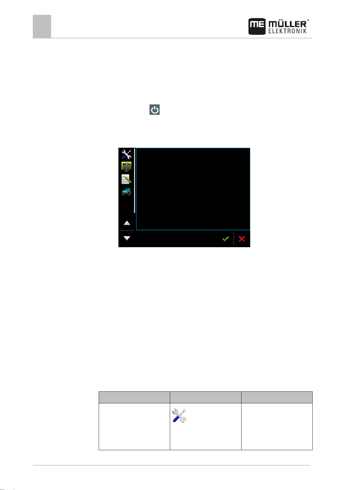
Switching on the terminal
To switch on the terminal:
The terminal is installed and connected to the power cable or the ISOBUS basic vehicle harness.
1. Press and hold the button for approx. 3 seconds.
⇨ The terminal will beep briefly.
⇨ The terminal screen remains dark for approx. 10 seconds until the applications are loaded in
the background.
⇨ The Start screen of the terminal will appear:
⇨ You have now started the terminal.
Initial start-up
The next step to perform after switching on the terminal depends on the purpose of the terminal:
▪ Parallel guidance
▪ Operation of ISOBUS implements
▪ Automatic section control
▪ Task processing and documentation
These cases will be described in the following sections.
Using the terminal for parallel guidance
If you want to use the terminal for parallel guidance, TRACK-Leader is the most important app for
you.
Most important settings
Page 21
Basic control principles
Initial start-up
5
31302713-02-EN
V5.20170221
21
Setting
Where?
Purpose
receiver must be activated.
Enter the tractor geometry and
activate the tractor profile.
/ Settings
See:
- Managing the tractor profiles [
➙ 51]
- Tractor geometry [➙ 56]
Virtual job computer
/ Settings
For the system to be able to
know the working width and
other parameters of the
machine, you must create a
virtual job computer for every
non-ISOBUS-compatible
machine that you use.
See: Virtual ECU application [
➙ 59]
Setting
Where?
Comment
Select the GPS driver
(optional).
/ Driver / GPS [➙ 29]
The standard driver works in
most cases for the receivers
sold by ME. However, to
change the correction signal, a
fitting driver for the GPS
receiver must be activated.
Enter the tractor geometry and
activate the tractor profile.
/ Settings
See:
- Managing the tractor profiles [
➙ 51]
- Tractor geometry [➙ 56]
5.2.2
Procedure
5.2.3
Other settings must be made in the TRACK-Leader application.
Operating an ISOBUS implement
If you purchase and activate an ISOBUS terminal licence, you can operate ISOBUS implements. In
the standard version of the terminal, you can test the function for 50 hours.
The "ISOBUS-UT" licence is activated.
1. Insert the ISOBUS cable of the job computer into the ISOBUS rear socket.
2. Switch on the terminal.
3. Wait until the job computer application has copied all of the relevant data on the terminal.
4. Open the job computer application using the selection menu [➙ 24].
Terminal for automatic section control
Most important settings
Page 22

5
Basic control principles
Initial start-up
22
V5.20170221
31302713-02-EN
Setting
Where?
Comment
Connecting the job computer to
the ISOBUS.
Job computer profile in
SECTION-Control
/ Settings / SECTION-
Control
Search for a profile and set the
"Machine model" parameter.
For more precise operation,
configure all of the other
parameters in the profile.
Setting
Where?
Purpose
Set the operating mode to
"Extended".
/ Settings
Activates and deactivates task
management in the ISOBUSTC application.
If you do not want to create
tasks, set the operating mode to
"Standard".
Insert the USB memory device
with task data or create tasks
without a USB memory device.
Procedure
5.2.4
Procedure
The "ISOBUS-UT", "TRACK-Leader" and "SECTION-Control" licenses are activated.
1. Insert the ISOBUS cable into the ISOBUS rear socket.
2. Switch on the terminal.
3. Wait until the job computer application has copied all of the relevant data on the terminal.
4. - Open the TRACK-Leader application using the selection menu [➙ 24].
5. Configure the settings from the table above.
6. Start a new navigation.
You can read how to proceed in the operating instructions for TRACK-Leader.
Terminal for task processing
You can always use ISOBUS-TC task processing, regardless of whether you are driving in parallel,
switching sections or simply operating an ISOBUS job computer. However, the most important
settings mentioned in the previous sections must be made for each of these applications.
Important for ISOBUS-TC:
▪ Always remember to start and stop the tasks.
▪ After finishing work, you must save all of the tasks on the USB memory device (log out the USB
memory device) before you remove the USB memory device or transmit new tasks onto the
terminal.
Most important settings
The "ISOBUS-TC" licence is activated.
Page 23
Basic control principles
Switching off the terminal
5
31302713-02-EN
V5.20170221
23
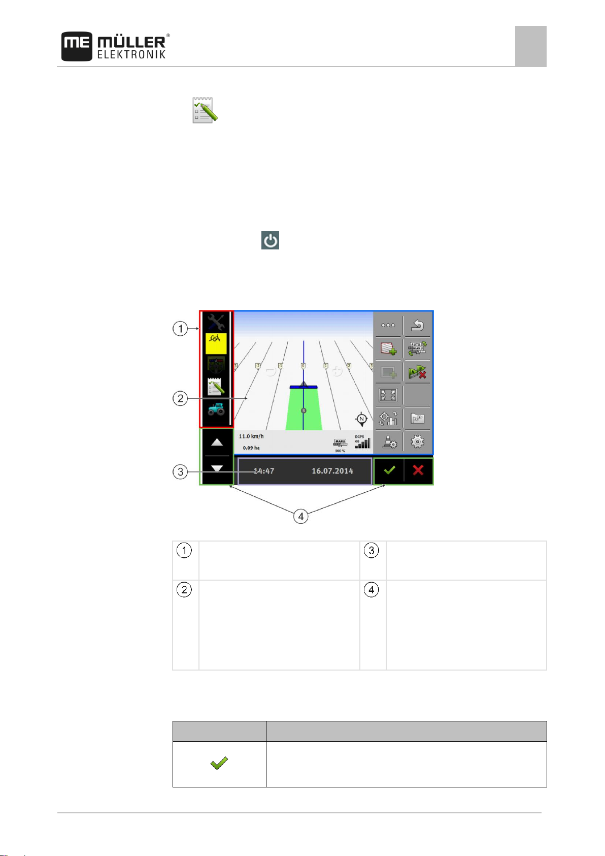
Selection menu
You can open applications in the "Selection
menu" area.
Wide additional window
Main window
This area enables you to operate applications.
Touching the terminal screen in the "Main
window" area will actuate the function whose
icon you have touched.
The controls depend on the opened
applications.
System icons
Icon
Meaning
Has no function in this area.
When this icon appears in other areas, it is used for confirmation
5.3
Procedure
5.4
1. Switch on the terminal.
2. - Open the ISOBUS-TC application using the selection menu [➙ 24].
3. Insert a USB memory device with task data.
4. Start a task.
Switching off the terminal
To switch off the terminal:
1. Press and hold the button for approx. 3 seconds.
⇨ You have now switched off the terminal.
Terminal screen layout
Terminal screen layout
System icons
Page 24
5
Basic control principles
Opening applications
24
V5.20170221
31302713-02-EN
Icon
Meaning
purposes.
Has no function in this area.
When this icon appears in other areas, it is used for cancellation or
deletion purposes.
Has no function in the current software version.
Has no function in the current software version.
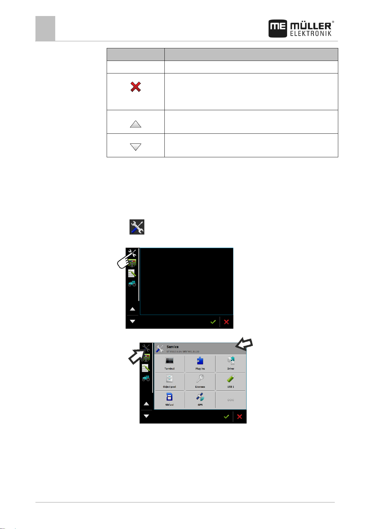
5.5
Procedure
Opening applications
An application opens when it appears in the main window or in an additional window.
To open an application:
1. Find the function icon for the desired application in the Selection menu area. For example, the
icon:
2. Tap the function icon of the application:
⇨ The application will appear in the main window:
⇨ The function icon of the application in the Selection menu now appears darker. This tells
you that this application is already open. You will no longer be able to open it from the
Selection menu.
⇨ If the main window is occupied, the application that is already opened will be moved to a
free additional window. If this is occupied, the application that is already opened will be
moved back to the Selection menu. Their icon becomes bright again. However, it can
continue to work in the background.
Page 25
Basic control principles
Moving an application
5
31302713-02-EN
V5.20170221
25
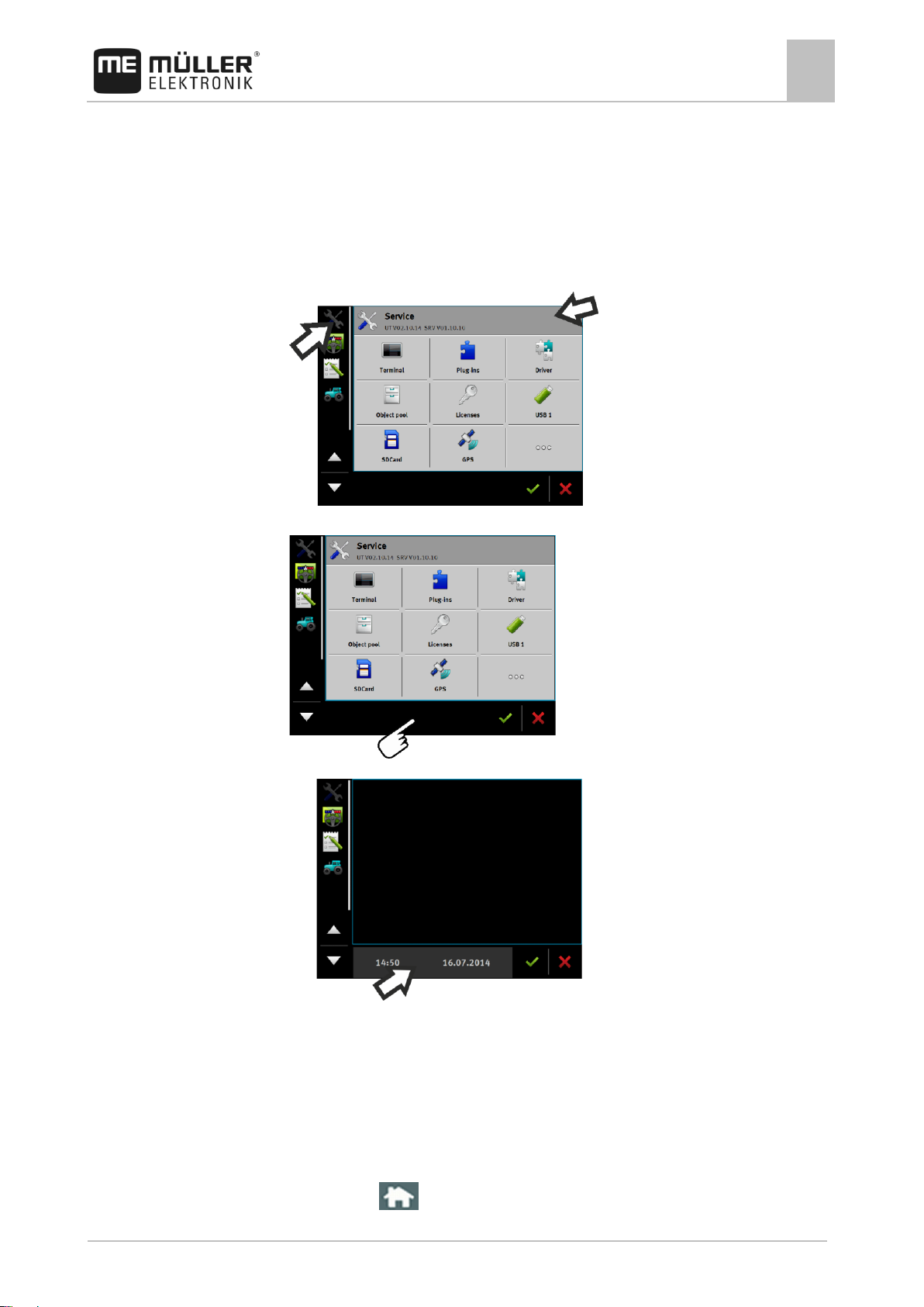
5.6
Procedure
5.7
Procedure
Moving an application
You can move any application from the main window to one of the additional windows or to the MEHeader.
To move an application from the main window to an additional window:
You have opened an application in the main window. For example, the Service application:
1. Tap the additional window:
⇨ The application will now appear in the additional window:
2. Tap the additional window with the application.
⇨ The application will once again appear in the main window.
Saving and loading window arrangements
You can save and load the arrangement of the applications in the windows.
To save the arrangement:
1. Hold the button pressed down until the terminal beeps twice.
Page 26

5
Basic control principles
Hiding an application
26
V5.20170221
31302713-02-EN
Icon
Meaning
12#
Abc
Changes the buttons on the keyboard.
Deletes a character.
Moves the cursor.
Saves the input.
Cancels the input.
Switches between upper and lower case letters.
Procedure
5.8
Procedure
5.9
⇨ The arrangement will be saved.
To load a saved arrangement:
1. Briefly press the button:
⇨ The arrangement will be loaded.
Hiding an application
If you do not have enough space on the terminal screen to open new applications, you can hide an
application. The application will not be shut down, but will instead continue to run in the background.
To hide an application:
1. Open the application in the additional window.
2. Move the application to the selection menu.
Using the keyboard
In order to enable you to also write numbers or text on the terminal, a keyboard will appear on the
terminal screen whenever this is necessary.
Major icons
Page 27

Basic control principles
Using a memory device
5
31302713-02-EN
V5.20170221
27
5.10
5.10.1
5.10.2
Keyboard for inputting text and numbers.
Keyboard for inputting text.
Using a memory device
The terminal can work with two kinds of memory devices:
1. With an integrated micro-SD card. This will be used as storage for most applications.
2. With an inserted USB memory device.
The USB memory device is used only for the following purposes:
▪ For data transfer [➙ 27] between the terminal and PC
▪ For saving screenshots
Using a SD card
The terminals applications save most data [➙ 27] directly onto the SD card.
In order to exchange data between the terminal and a PC, you will need to proceed differently for
each application. You can find out more about this in the instructions for each application.
Folders on the USB memory device
As soon as you insert the USB memory device into the terminal, several folders will be created on the
USB memory device. You will need to set up other folders by yourself.
Each folder may only contain certain data, so that the applications on the terminal can use this data.
▪ "documents"
– Files: .txt
– Purpose: Records for all completed tasks are saved in this folder.
▪ "FIELDNav"
– Files: .iio, .data
– Purpose: Map material will be saved in this folder.
– The folder will be created when the FIELD-Nav license is activated.
Page 28

5
Basic control principles
Using a memory device
28
V5.20170221
31302713-02-EN
5.10.3
Procedure
▪ "fileserver"
– Files: All file formats are acceptable.
– Purpose: Files which are to be imported or exported in the File Server application are saved
in this folder.
▪ "GPS"
– Files: .txt
– Purpose: GPS positions are saved in a file in the folder. This will enable Customer Service
to reconstruct the traveled distance.
– The folder will be created if you activate the "Record and save data" parameter.
▪ "NgStore"
– Files: .iio, .data
– Purpose: TRACK-Leader. Standard folder for saved routes and fields.
▪ "Screencopy"
– Files: .bmp
– Purpose: Screenshots are saved here.
– The terminal will create this folder automatically when the "Screenshot" parameter is
activated in the "Terminal" menu and you create a screenshot.
▪ "SHP"
This folder replaces the "GIS" folder that was used in previous versions.
– Files: .dbf, .kml, .prj, .shp, .shx
– Purpose: TRACK-Leader: After saving with the SD card, the field data will be stored here.
For example: Field boundaries, applied areas, headlands, etc.
ISOBUS-TC: The shp files must be stored in this folder.
▪ "Taskdata"
– Files: .xml
– Purpose: The folder may only contain XML files which originate from an ISO-XML
compatible FMIS. The ISOBUS-TC application accesses this data.
– You must create this folder yourself.
Displaying the content of the memory device on the terminal
You can view the content of the memory device directly on the terminal.
1. Insert the memory device (USB memory device or SD card) into the terminal.
2. Open the "Service" application.
3. Tap on "USB 1" or on "SDCard".
⇨ The content of the USB memory device will be displayed.
⇨ The content of the SD card can be found in the "ME-TERMINAL" folder.
Page 29

Connecting and configuring external devices
GPS receiver
6
31302713-02-EN
V5.20170221
29
Frequencies
5 Hz (GPGGA, GPVTG)
1 Hz (GPGSA, GPZDA)
Transmission rate
19200 baud
Data bits
8
Parity
no
Stop bits
1
Flow control
None
6
6.1
6.1.1
Procedure
6.1.2
Connecting and configuring external devices
GPS receiver
Connecting the GPS receiver to the terminal
Find out how to connect Müller-Elektronik GPS receiver to the terminal via the GPS receiver's
Operating Instructions.
When mounting the terminal in a vehicle which is already fitted with a GPS receiver and another
ISOBUS terminal, you must:
▪ connect the GPS signal to the terminal from Müller-Elektronik;
▪ configure the GPS receiver.
To connect the terminal to a GPS receiver which is already installed on the vehicle:
1. Find out how you can direct the signal from the GPS receiver to the terminal. This can differ for
every vehicle or GPS receiver: Vehicles can be fitted with a GPS socket in the cab, a GPS
receiver with a serial output or serial outputs to the ISOBUS terminal.
2. Check what cable you will use to connect GPS signal to the serial socket on the terminal from
Müller-Elektronik.
3. Connect the GPS signal to the serial socket of the terminal from Müller-Elektronik.
4. Configure the GPS receiver so that it can communicate with the terminal from Müller-Elektronik.
You can find the necessary specifications for this in the table below.
5. Activate the "Standard" GPS driver on the terminal.
Configuration
Changing the driver for the GPS receiver
Upon delivery, the "Standard" driver is activated on the terminal. You must change this driver if you
want to reconfigure the GPS receiver, for example, to change the correction signal. In this case, you
must select a driver that is fitting for the GPS receiver.
Page 30

6
Connecting and configuring external devices
GPS receiver
30
V5.20170221
31302713-02-EN
Driver name
GPS receiver
deactivated
No GPS receiver is connected.
A100, A101
Drivers for the A100 and A101 GPS receivers from MüllerElektronik, if they are connected to the serial interface.
AG-STAR, SMART-6L
Drivers for the AG-STAR and SMART-6L GPS receivers from
Müller-Elektronik, if they are connected to the serial interface.
PSR CAN
Select this driver if the GPS receiver is connected to the PSR
steering job computer. PSR is a steering computer by the
Reichhardt company. The signals are transmitted to the terminal
through the CAN cable. The receiver will be configured directly in
the PSR application.
Please note that you cannot use this driver together with an
external lightbar.
Standard
Drivers for unknown GPS receivers, if they are connected to the
serial interface.
This driver is activated by default. The connected GPS receiver
cannot thus be configured.
TRACK-Leader AUTO®
Select this driver if a GPS receiver is connected to the TRACKLeader AUTO® steering job computer.
Please note that you cannot use this driver together with an
external lightbar.
NOTICE
Incorrect driver
Damage to the GPS receiver.
◦ Before connecting a GPS receiver to the terminal, you must always activate the appropriate
driver.
Procedure
Available drivers
To activate the driver:
1. - Open the Service application.
2. Tap "Driver".
3. Tap "GPS".
⇨ The installed drivers will appear.
4. Tap the appropriate driver.
5. - Confirm.
6. Restart the terminal.
Page 31

Connecting and configuring external devices
GPS receiver
6
31302713-02-EN
V5.20170221
31
Function icon
Meaning
Reads the configuration of the GPS receiver.
Restores the manufacturer's default settings.
Opens the license menu.
Only appears on SMART-6L DGPS/GLONASS receivers for entering an
activation license.
Resets the baud rate.
6.1.3
Procedure
Configuring the GPS receiver
The internal software for each GPS receiver must be configured. You can configure the following
GPS receivers offered by Müller-Elektronik via the terminal:
▪ A100, A101
▪ AG-STAR, SMART-6L
All other GPS receivers must be configured in accordance with their manufacturer's instructions.
The GPS receiver is connected to the terminal.
The GPS receiver is connected directly to the terminal. Additional devices such as an external
lightbar or tilt module may not be connected in between.
The correct GPS driver is activated.
1. - Open the "Service" application.
2. Tap "GPS".
⇨ The "Settings" screen appears.
⇨ The following message will appear during initial configuration: "GPS receiver detected.
Read the configuration?"
3. To confirm, tap "Yes". To cancel, tap "No".
⇨ The terminal reads the current configuration of the GPS receiver.
⇨ You can now see all of the configurable parameters.
4. Configure the parameters. The parameters can be found in the following section.
5. Reconnect all of the additional devices that you had disconnected for the configuration.
Parameters for the GPS receiver
Baud rate
Only appears when the "Standard" driver is selected.
Setting for the speed at which the GPS receiver sends data to the terminal. The parameter sets the
baud rate for the terminal.
Satellite 1 and Satellite 2
Page 32

6
Connecting and configuring external devices
GPS receiver
32
V5.20170221
31302713-02-EN
Satellite 1 – primary DGPS satellite. The DGPS receiver will connect to this satellite in the first
instance.
Satellite 2 – secondary DGPS satellite. The DGPS receiver will only connect to this satellite in the
event that the primary satellite fails.
Your satellite selection will depend on which satellite currently has the best availability in your region.
Possible values:
▪ "Auto"
The software automatically selects the current best satellite.
▪ Name of the satellite. Which satellites are shown here is dependent on the driver and correction
signal that you have activated.
Steering
This parameter activates the "Automatic steering" assistance function in the GPS receiver.
If you want to connect your existing GPS receiver to a steering job computer, you have to configure
the "Steering" parameter.
Possible values:
▪ "Without automatic steering"
Deactivates automatic steering assistance.
▪ "TRACK-Leader TOP"
Activates automatic steering assistance with TRACK-Leader TOP.
▪ "TRACK-Leader AUTO"
Activates automatic steering assistance with TRACK-Leader AUTO.
Correction signal
Type of correction signal for the DGPS receiver.
The correction signals which are available is dependent on the activated driver.
Possible values:
▪ For the "A100, A101" driver:
– "WAAS/EGNOS"
Correction signal for Europe, North America, Russia and Japan.
– "E-DIF"
Internal calculation of correction data.
Only functions with a special version of the A100 DGPS receiver, item no. 30302464. This
receiver is no longer sold by Müller-Elektronik.
▪ For the "AG-STAR, SMART-6L" driver
When a AG-STAR DGPS/GLONASS receiver is connected:
– "EGNOS-EU"
– "WAAS-US"
– "MSAS-JP"
– "EGNOS-EU + GLIDE"
– "WAAS-US + GLIDE"
– "MSAS-JP + GLIDE"
– "GPS/GLONASS GLIDE 1"
Page 33

Connecting and configuring external devices
GPS receiver
6
31302713-02-EN
V5.20170221
33
– "GPS/GLONASS GLIDE 2"
When a DGPS/GLONASS receiver SMART-6L receiver is connected:
– EGNOS/WAAS
– EGNOS/WAAS + GLIDE
– GLIDE
– RTK radio (RTK licence required)
– RTK GSM (RTK licence required)
– TerraStar (RTK or L band licence required)
Information for GLIDE
If you have selected a correction signal with GLIDE, please note:
▪ Switch the GPS receiver off when driving on roads.
▪ After starting the systems each time, it takes ca. 5 minutes until the system is ready for
operation. Wait on the field to be worked during this time, before you start working.
▪ Ensure that the GPS receiver does not lose the GPS signal during work. If the signal gets lost, it
can cause the GLIDE to restart. This can lead to track offset.
Information for TerraStar
If you have selected "TerraStar" as a correction signal, please note:
▪ There are two different TerraStar correction signals: TerraStar-C and TerraStar-L. These differ
mainly in their accuracies.
▪ The accuracies are available ca. 5 to 10 minutes after switching on the GPS receiver under the
open sky.
▪ If the GPS signal fails due to shadowing by buildings or trees, the full accuracy is available again
at the latest after ca. 5 minutes. For this reason, you should avoid driving along rows of trees or
buildings.
▪ During the convergence, the GPS receiver and the vehicle should not be moved and the location
should not be changed.
Port B receiver baud rate
Only appears when the "RTK radio" correction signal is selected.
If you are using a GPS receiver with a radio modem from a third-party manufacturer, the baud rate
must be adjusted in some cases. The baud rate must then correspond to that of the radio modem.
The baud rate for radio modems manufactured by Müller-Elektronik is always 19.200 baud.
Correction in case of RTK failure
This parameter is only required if you are using the SMART-6L DGPS receiver with a steering
system.
Possible values:
▪ automatic
The parameter is activated.
When there is an RTK failure, a deviation arises between the current position of the vehicle and
the GPS position.
If the parameter is set to "automatic", you prevent the vehicle from driving directly to the new
GPS position. The system will then gradually steer towards the new GPS position. This prevents
the occurrence of large track offsets in case of RTK failure.
Page 34

6
Connecting and configuring external devices
GPS receiver
34
V5.20170221
31302713-02-EN
Procedure
Procedure
When the RTK signal is available again, the vehicle will be gradually steered towards the original
GPS position.
▪ deactivated
The parameter is deactivated.
Terrain compensation
The GPS TILT-Module terrain compensation is configured using this parameter.
You can order the terrain compensation from Müller-Elektronik with the following item number:
30302495.
RTK or L band licence for SMART-6L
You will need a SMART-6L DGPS/GLONASS receiver and RTK license in order to work with RTK
correction signals.
To work with TerraStar correction signals, you need a SMART-6L DGPS/GLONASS receiver and at
least an L band license.
When purchasing a GPS receiver with an RTK or L band license, the licence from Müller-Elektronik
will be entered. You only have to enter the licence yourself when it is purchased at a later date.
1. - Open the "Service" application.
2. Tap "GPS".
⇨ The "Settings" screen appears.
3. - Open the license menu.
4. Tap "License code".
⇨ The "License menu" screen appears.
⇨ You can see the serial number and firmware version on the screen. You will need these
when ordering the license code.
⇨ If you are using the TerraStar correction signal, you will see information on the TerraStar
service and the expiry date of the TerraStar service.
⇨ Optionally, you can open the "Model number" screen to obtain information on the current
activation of the GPS receiver.
5. Enter the license code.
6. - Confirm.
GSM modem for SMART-6L
If you are using the DGPS/GLONASS SMART-6L receiver with a GSM modem, you can adjust the
existing configuration.
1. - Open the "Service" application.
2. Tap "GPS".
3. The "Settings" screen appears.
4. - Open the configuration menu.
Page 35

Connecting and configuring external devices
GPS receiver
6
31302713-02-EN
V5.20170221
35
Parameter
Meaning
Possible entries
APN
Connection to the provider.
Provider URL or IP address.
User
Name for the Internet access. The name is the
same for all users of a provider.
Name that was given by the provider. Some
providers do not require entering a name.
Password
Password for the Internet access. The password is
the same for all users of a provider.
Password that was given by the provider.
Some providers do not require entering a
password.
URL/IP
Connection to the correction data server.
Correction data server URL or IP address.
Port
Port at the correction data server.
Port number
NTRIP user
Name from the correction service to identify the
customer account.
Letters and numbers. Pay attention to the
use of upper and lower case letters.
NTRIP password
Password for the identification name.
Letters and numbers. Pay attention to the
use of upper and lower case letters.
Mountpoint
Manual entry of a correction data source available
only with GPRS connections.
Name of the correction data source / data
stream.
Procedure
5. Configure the parameters. The explanations for the individual parameters can be found in the
table at the end of this section.
6. - Save the changes.
⇨ The following message appears: "Should the data be transmitted to the modem?"
7. "Yes" - to confirm.
⇨ The data is being transmitted to the modem. This will take approx. 30 seconds.
Configuring the GPS receiver for the steering system
To be able to use a GPS receiver with automatic steering, it must previously be configured for this
use. The configuration adjusts the internal settings of the GPS receiver.
You can use the following GPS receivers for the steering system:
▪ A101
▪ AG-STAR
▪ SMART-6L
To configure the GPS receiver for automatic steering:
1. Activate the driver for the respective GPS receiver [➙ 29] to establish a connection between the
terminal and the GPS receiver.
2. Configure the GPS receiver. [➙ 31]
3. Tap "Steering" in the configuration.
4. Select the automatic steering that you are using.
5. - Confirm.
Page 36
6
Connecting and configuring external devices
GPS receiver
36
V5.20170221
31302713-02-EN
Procedure
6.1.4
Procedure
6. For TRACK-Leader AUTO® systems, tap and adjust the baud rate of the receiver to the
automatic steering.
⇨ The following message appears: "You can now disconnect the GPS receiver."
7. Confirm using "OK".
8. Switch off the terminal.
9. Now connect the GPS receiver to the cable harness of the steering job computer.
10. Start the terminal.
11. Depending on the steering job computer, activate the "PSR CAN" or "TRACK-Leader AUTO"
driver. [➙ 29]
12. - Confirm.
13. Restart the terminal.
⇨ The GPS receiver is now configured for automatic steering.
To change parameters for the GPS receiver after the GPS receiver has been configured for
automatic steering, you must restore the internal settings of the GPS receiver.
1. Connect the GPS receiver to the terminal.
2. Activate the driver for the respective GPS receiver. [➙ 29]
3. Restart the terminal.
4. - Open the "Service" application.
5. Tap "GPS".
6. - Reset the baud rate.
7. The following message appears: "Should the standard baud rate be restored?"
8. Confirm using "OK".
9. Restart the terminal.
⇨ You can now change the individual parameters for the GPS receiver.
⇨ After you have changed the parameters, you can reconfigure the GPS receiver for the steering.
Recording GPS positions
Certain faults can require recording of the position data from the GPS receiver.
A USB memory device is inserted into the terminal.
1. - Open the Service application.
2. Tap "GPS".
3. Tap "GPS-Data".
⇨ The "GPS-Data" screen will appear.
4. Scroll down.
Page 37

Connecting and configuring external devices
Configuring the joystick button allocations
6
31302713-02-EN
V5.20170221
37
6.1.5
Procedure
6.2
Procedure
5. Tap "Trace-Data".
⇨ The "Trace-Data" screen will appear.
6. Scroll down.
7. Checkmark the "Record and save data" button.
⇨ The terminal will immediately begin to record the data. This will be saved in the "GPS" folder
on the USB memory device.
⇨ The function will be deactivated following any restart.
Configuring the "GPS TILT-Module" terrain compensation
The "GPS TILT-Module" terrain compensation is connected.
The tractor is positioned on level ground.
The lightbar driver is configured as a "screen lightbar".
1. If additional devices (e.g. external lightbar) are connected to the cable between the terminal and
the tilt module, disconnect them. The tilt module must be connected directly to the terminal. After
the tilt module has been configured, these additional devices must be reconnected.
2. Measure the distance between the GPS receiver and the ground on which the tractor is
positioned.
3. Switch on the terminal.
4. - Open the "Service" application.
5. Tap "GPS".
⇨ The "Settings" screen appears.
6. Scroll down until the "Terrain Compensation" parameter appears on the screen.
7. Tap "Terrain Compensation".
8. Enter the measured distance on the "GPS receiver height" line.
9. Tap .
⇨ Message: "Tilt module will be configured." is displayed.
10. To confirm, tap "Yes".
⇨ The position of the tilt module on level ground is being calibrated.
⇨ After calibration, the angle 0 will appear on the "Angle" line. The displayed angle will change
with any tilt of the tractor.
11. Reconnect all of the additional devices that you had disconnected for the configuration.
Configuring the joystick button allocations
The terminal offers you the possibility of assigning the functions of an ISOBUS job computer to the
buttons of the joystick. To do so, the ISOBUS job computer and the joystick must fulfil the Auxiliary 2
specification requirements from the ISOBUS standard.
To activate the driver for this function:
The joystick and ISOBUS job computer are connected and both support the Auxiliary 2 protocol.
Page 38
6
Connecting and configuring external devices
Connecting sensors to the terminal
38
V5.20170221
31302713-02-EN
Adapter cable
Item number
3-pin to 9-pin
31302499
Procedure
6.3
1. - Open the Service application.
2. Tap "Driver".
3. Tap "Auxiliary".
4. Mark "Auxiliary2".
5. - Confirm.
6. Restart the terminal.
To configure the button assignment:
You have activated the driver "Auxiliary2"
1. - Open the Service application.
2. Tap "Auxiliary".
3. Tap "Auxiliary Editor".
⇨ If the ISOBUS job computer supports the Auxiliary 2 protocol, a list will appear of the job
computer functions.
⇨ If no list appears, the ISOBUS job computer does not support this protocol.
4. Tap the function which you want to assign to this button on the joystick.
⇨ A list of the buttons on the joystick will appear.
5. Select the button to which the selected function should be assigned.
6. - Confirm.
⇨ A list of assignments will appear.
7. Restart the terminal.
⇨ After restarting, the following notification will appear on the main terminal screen: "Confirm
the assignments." This notification will appear after any restart.
8. "OK" - acknowledge the notification.
⇨ A list of recognized assignments will appear on the terminal screen.
9. - Confirm the assignments.
Connecting sensors to the terminal
The terminal provides you with the possibility of connecting a sensor or the tractor's 7-pole signal
socket to port B. This allows you for example to use the working position signal in the TRACK-Leader
parallel guide.
The work position sensor sold by Müller-Elektronik is fitted with a round 3-pin plug. You will need an
adapter cable to connect it to the terminal.
Adaptor cable for the ME sensor Y work position sensor
Page 39

Connecting and configuring external devices
Camera
6
31302713-02-EN
V5.20170221
39
Ports
Connection
Item number
7-pin to 9-pin socket
Cable directly to the signal socket
Transmits the speed and working
position.
30322548
Plug for connection to the terminal.
CAM port
Camera HQ2
Extension cable
Camera plug
Connector for the camera plug
6.4
6.4.1
Procedure
You can also connect the terminal to the signal socket.
Cable to the signal socket
You must activate the work position sensor [➙ 54] and possibly the wheel sensor [➙ 53] or radar
sensor in the Tractor-ECU app and calibrate if necessary.
Camera
Connecting the camera to the terminal
Connecting the camera HQ2
Camera HQ2 - Connection to the Touch Terminal
1. Assemble the camera together with its bracket, as described in the assembly instructions of the
camera manufacturer.
2. Connect the camera to the extension cable.
3. CAUTION! When laying out the extension cable, ensure that there are no kinks and that
no one can stumble over the laid-out cable.
4. Connect the extension cable to the CAM port of the terminal.
5. Secure the camera.
6. Activate the camera. [➙ 40]
Page 40

6
Connecting and configuring external devices
Camera
40
V5.20170221
31302713-02-EN
Plug for connection to the terminal.
CAM port
Camera
Connector for the adapter cable
Camera plug
Connector for the extension cable
Connector for the camera plug
Procedure
6.4.2
Procedure
Connecting the camera NQ
Camera with adapter cable
1. Connect the cables to each other as shown in the figure. Pay attention to cable lengths when
doing so.
2. CAUTION! When laying out the cable, ensure that there are no kinks in the cable and that
no one can stumble over the laid-out cable.
3. Lay out the cable. Ensure that the cable reaches the terminal and is not pulled out during
operation.
4. Attach the cable with the provided cable ties.
5. Secure the camera. Use the white cardboard drilling template from the quick start guide for this
purpose.
6. Connect the camera to the terminal. Use the CAM port to do this.
7. Activate the camera. [➙ 40]
8. When disconnecting the cable from the terminal, use the enclosed rubber gasket to seal the
exposed connector.
Activating a camera
In order to activate a camera, you must activate the "Camera" plug-in.
1. - Open the Service application.
2. Tap "Plug-ins".
3. Tap "Camera".
⇨ The plug-in is marked with a green tick.
4. Restart the terminal.
Page 41

Connecting and configuring external devices
External lightbar
6
31302713-02-EN
V5.20170221
41
WARNING
Accident due to delayed image transmission
Rapidly moving objects may be detected too late.
◦ Do not use the camera as an aid for steering the vehicle.
◦ Do not use the camera in road traffic.
◦ Do not use the camera when driving into intersections.
◦ Do not use the camera as a rear view camera.
◦ Do not use the camera as a visual aid for controlling the implement, especially when a delayed
reaction can lead to risks.
Function icon
Meaning
Mirrors the image horizontally.
Mirrors the image vertically.
6.4.3
6.5
6.5.1
⇨ After restarting, the icon for the camera application will appear in the selection menu.
5. - Open the Camera application.
Operating the camera
The camera serves solely for observing the implement functions in non-safety-related working areas
of the agricultural implement.
In certain situations, the camera image may appear on the screen with a delay. The delay depends
on the respective use of the terminal and can also be affected by external factors and devices.
You have connected and activated the camera.
1. - Open the Camera application.
⇨ The image will appear in the main window.
2. Tap on the main window.
⇨ Function icons will appear on the side for 10 seconds, with which you can actuate the
External lightbar
camera.
Connecting the external lightbar to the terminal
The external lightbar is a parallel guidance display made by Müller-Elektronik, which can be mounted
near the windshield.
The external lightbar works with position data and guidance lines that are provided by the TRACKLeader app. This is why you need the TRACK Leader App to be able to use the external lightbar.
Page 42

6
Connecting and configuring external devices
Connecting the on-board integrated display/controller to the terminal
42
V5.20170221
31302713-02-EN
External lightbar
Plug for connection to the terminal
Plug for connecting a GPS receiver
Serial port
6.5.2
Procedure
6.6
Activating an external LightBar
If you connected an external LightBar to the terminal, you must activate it.
To activate the external LightBar, you must first activate its driver.
You can order the external LightBar from Müller-Elektronik with the following item number: 30302490.
1. - Open the Service application.
2. Tap "Driver".
3. Tap "LightBar".
⇨ The installed drivers will appear.
4. Tap "Lightbar".
5. - Confirm.
6. Restart the terminal.
Connecting the on-board integrated display/controller to the
terminal
You can connect a range of on-board integrated display/controllers (non-ISO computers), which
communicate using the LH5000 protocol or the ASD interface, to the terminal.
An appropriate connector cable for each on-board integrated display/controller which can be
connected is available from Müller-Elektronik. Our sales team will be glad to advise you.
Page 43

Connecting and configuring external devices
ISO printer
6
31302713-02-EN
V5.20170221
43
On-board display/controller
Null modem cable
Adapter cable*
Available as a set with Cable 3, item number:
3032254800
Port B on the terminal
9-pin Sub-D plug for connection to ISOBUS
Plug for connection to ISO printer socket
ISO printer
Connector for connection to the terminal
ISO printer socket
CAN-Bus connection
Procedure
6.7
6.7.1
*When using an Amatron3 or Amatron+ as on-board integrated display/controller, you will only need a
traditional null modem cable. (Amatron3 and Amatron+ are on-board integrated display/controller
from Amazone)
1. After connecting the on-board integrated display/controller to the terminal, create a virtual job
computer for the machine. More about this in section: Virtual ECU application [➙ 59]
ISO printer
Connecting the ISO printer to the terminal
The ISO printer is used to print out information from an ISO-XML task.
Page 44
6
Connecting and configuring external devices
Configuring the Bluetooth connection in the Connection Center
44
V5.20170221
31302713-02-EN
6.7.2
Procedure
6.8
Procedure
6.9
Procedure
Activating the ISO printer
In order to activate the ISO printer, you must activate its driver.
1. - Open the Service application.
2. Tap "Driver".
3. Tap "ISOPrinter".
⇨ The installed drivers will appear.
4. Tap "ISO Printer".
5. - Confirm.
6. Restart the terminal.
Configuring the Bluetooth connection in the Connection Center
If you connect a bluetooth stick to the terminal, you can couple the terminal with another bluetooth
device (e.g. a smartphone).
This allows you to use the ME ODI (Müller Elektronik Open Data Interface) [➙ 13] application.
1. Connect the USB bluetooth stick to the terminal.
2. - Open the "Service" application.
3. Tap "Driver".
4. Activate the "Connection Center" driver (value: Connection Center)
5. Restart the terminal.
6. - Open the "Service" application.
7. Tap on “...”.
8. Tap on “Connection Center”.
⇨ The “Connection Center” screen appears.
9. Tap on "Bluetooth".
Crop protection sensors
Crop protection sensors measure the plant requirements during operation. Depending on the sensor,
the results are transmitted as a target rate to the job computer of the fertilizer spreader or sprayer.
The terminal can communicate with crop protection sensors through two interfaces:
▪ ISOBUS - If a sensor communicates via ISOBUS, it is automatically detected by the terminal.
The target rates are transmitted directly to the job computer.
▪ Serial - If a sensor only communicates through the serial interface, you must connect it to the
serial port on the terminal [➙ 78]. Then you must create a virtual job computer for the sensor in
the Virtual ECU [➙ 59] app. Activate the virtual job computer before starting operation.
To work with ISOBUS sensors:
Page 45

Connecting and configuring external devices
Crop protection sensors
6
31302713-02-EN
V5.20170221
45
Procedure
1. Connect the sensor to the ISOBUS.
2. Follow the instructions from the sensor manufacturer. The terminal does not need to be
configured.
To work with serial connection sensors:
1. Connect the sensor to the serial port of the terminal.
2. Create a virtual job computer in the Virtual ECU app. [➙ 59]
3. In the "External controller" [➙ 60] parameter, select the sensor type.
4. Activate the job computer for the sensor.
⇨ You have activated the sensor.
⇨ The terminal transmits all target rates to ISOBUS-TC, the ISOBUS job computer and TRACK-
Leader.
Page 46

7
Configuring the terminal in the Service application
Changing the language
46
V5.20170221
31302713-02-EN
7
7.1
Procedure
7.2
Procedure
Configuring the terminal in the Service application
Changing the language
If you change the language in the Service application, you also change the language for all
applications and the ISOBUS job computer.
If a connected ISOBUS job computer cannot activate the selected language, a standard language will
be activated.
1. - Open the Service application.
⇨ The application start screen will appear:
2. Tap "Terminal".
⇨ A list of parameters will appear.
3. Slide your finger over the terminal screen from the bottom to the top.
⇨ New parameters appear.
4. Tap "Language" ("Sprache").
⇨ A list of abbreviations of available languages will appear.
5. Tap the abbreviation for your language.
⇨ The abbreviation is marked with a green dot.
6. - Confirm.
⇨ The "Terminal" screen will appear.
7. Restart the terminal.
Basic settings
The basic settings include: Language, Time, Measurement units.
All settings which you make here will also apply to other applications and in connected ISOBUS job
computers.
1. - Open the Service application.
Page 47

Configuring the terminal in the Service application
Basic settings
7
31302713-02-EN
V5.20170221
47
Parameter name
Function
Brightness Day
Brightness of the terminal screen during the day.
Brightness Night
Brightness of the terminal screen at night.
Keyboard brightness
Lighting of the buttons.
Volume
Volume of the terminal.
Date
Current date.
Time
Current time.
Time zone
Time difference in relation to GMT.
Language
Language of the applications on the terminal screen.
Measurement units
Measurement system.
Screenshot
When this parameter is activated, you can create screenshots on
the terminal.
UT number
Parameters from the ISO standard
Number that should be given to the terminal on the ISOBUS.
Login as ISOBUS-UT
Activate this parameter if you want the ISOBUS job computer to
be displayed on the terminal. This parameter must be activated in
most instances. On very few self-propelled agricultural machines,
the parameter must be deactivated.
⇨ The application start screen will appear:
2. Tap "Terminal".
⇨ A list of parameters will appear. See the table below.
3. To change the value of any of the parameters, tap the desired parameter.
⇨ A window will appear, into which you can input the value of the parameter as a number, or
select from a list.
4. - Confirm.
5. Restart the terminal.
Parameters in the "Terminal" menu
Page 48
7
Configuring the terminal in the Service application
Enabling and disabling applications
48
V5.20170221
31302713-02-EN
Parameter name
Function
Number of navigation buttons
The terminal provides a maximum of 12 function icons in each
application.
When you connect an ISOBUS job computer that has more
functions in a single screen to the terminal, their function icons
are spread over multiple pages. Furthermore, navigation buttons
appear that can be used to scroll to the next page.
The number indicates how many buttons should be used to scroll
between multiple pages with function icons.
Name of the plug-in
Activates the following applications
TRACK-Leader
TRACK-Leader
SECTION-Control
TRACK-Leader TOP
TRACK-Leader AUTO
ISOBUS-TC
ISOBUS-TC task processing [➙ 63]
Tractor-ECU
Tractor-ECU application [➙ 51]
Camera
The terminal screen will show the image from the connected
camera.
FIELD-Nav
FIELD-Nav
File Server
File Server application [➙ 75]
Virtual ECU
Virtual ECU application [➙ 59]
7.3
Procedure
Enabling and disabling applications
In the "Service" application you can activate and deactivate other applications that are installed on
the terminal.
The applications are installed in packages, in so-called plug ins. A plug-in can contain several
applications.
You can for example deactivate a plugin if you do not want to use it. The plug-in will then not be
displayed in the selection menu.
To activate and deactivate plug-ins:
1. - Open the Service application.
2. Tap "Plug-ins".
⇨ The "Plug-ins" screen will appear.
3. To activate or disable a plug-in, tap it.
⇨ A plug-in is activated when a checkmarker appears in front of its name.
Page 49

Configuring the terminal in the Service application
Unlocking licenses for full versions
7
31302713-02-EN
V5.20170221
49
Screen name
Name of the application
Unlocked applications are marked with check
marks.
You can see how long you can still use a test
version in the brackets: in hours and minutes.
Un-checked applications are locked.
18-digit alphabetical code of the application
7.4
Procedure
4. Restart the terminal.
Unlocking licenses for full versions
Several applications are pre-installed on the terminal, which you can use for trial purposes for up to
50 hours. After this time has elapsed, they will be automatically deactivated.
"Licenses" screen
You will need an activation key to unlock a license. To receive this, you will need to purchase a
license from Müller-Elektronik.
If you request the activation key by phone or by email, you will be required to give our staff the
following information:
▪ The name of the application for which you require a license.
▪ The 18-digit alphabetical code of the application. You will find this on the "Licenses" screen.
▪ Serial number of the terminal – Found on the nameplate on the reverse of the terminal.
▪ Item number of the terminal – Found on the nameplate on the back of the terminal.
To unlock a license:
1. - Open the Service application.
2. Tap "Licenses".
3. Order an activation key from Müller-Elektronik using the 18-digit alphabetical code.
4. Tap the name of the license that you want to unlock.
⇨ The keyboard will appear.
5. Enter the activation key.
6. - Confirm.
⇨ The "Licenses" screen will appear.
7. Restart the terminal.
⇨ The full version of the application is now unlocked.
Page 50

7
Configuring the terminal in the Service application
Creating screenshots
50
V5.20170221
31302713-02-EN
7.5
Procedure
7.6
When to delete?
Procedure
Creating screenshots
A screenshot is a photo of the screen being displayed.
1. Insert a USB memory device into the terminal.
2. - Open the Service application.
3. Tap "Terminal".
4. Set the "Screenshot" parameter to "Activated".
5. To create a screenshot, press the button.
⇨ The content of the terminal screen will be saved as an image file on the USB memory
device in the "Screencopy" folder.
Deleting pools
Pools are the intermediate storage for the terminal. Pools are used to temporarily store graphics or
text. Over time, the pools will become too large and slow down the operation of the terminal.
You can delete the pools to speed up the terminal's operation.
Delete the pools:
▪ After updating the software of a connected job computer.
▪ If the terminal operates more slowly than usual.
▪ When asked to do so by Customer Services.
To delete the pools:
1. - Open the Service application.
2. Tap "Object pool".
⇨ A list with the ISO names of ISOBUS job computers will appear, whose graphics and text
can be found in the storage of the terminal. You can determine from the icon which farm
implement is being controlled by the job computer.
3. Tap the object pool which you want to delete.
4. - Delete the object pool.
⇨ Don't worry if you delete the wrong object pool. it will be reloaded.
⇨ The following message will appear: "Do you want to delete the folder?"
5. To confirm, tap "Yes".
6. The current pool of the job computer will be loaded after the next restart.
Page 51

Tractor-ECU application
Work screen
8
31302713-02-EN
V5.20170221
51
Speed display
PTO shaft speed
Speed source
Number of operation hours
Position of the work position sensor
Status of the work position sensor
8
8.1
8.2
Tractor-ECU application
The Tractor-ECU application is used to compile all of the information of the vehicle on which the
terminal is mounted. Tractor-ECU can transfer this information to other apps (e.g. the position of the
GPS receiver to TRACK-Leader or SECTION-Control) or to a connected ISOBUS job computer (GPS
signal as a speed source).
The Tractor-ECU application allows you to:
▪ Create a profile for each vehicle, with specific settings.
▪ Input the sensors which are mounted on the vehicle.
▪ Input the position of the GPS receiver.
▪ Define the GPS signal to determine the speed on the CAN bus.
Work screen
Managing the tractor profiles
Tractor profiles are used to store important features of the tractor on which the terminal is installed.
This offers the following advantages:
▪ You can use the terminal on several tractors. Each time you change tractors, you can activate
the fitting tractor profile.
▪ Even if the terminal is always installed on one tractor, you can create several profiles for one
tractor.
You can use between 1 and 31 tractor profiles.
The number of tractor profiles depends on several factors:
▪ Purpose of the terminal:
– If you switch the mounted implement manually, or are using an implement for which cm-
accuracy is not required, one tractor profile per tractor is enough.
– If you are not using TRACK-Leader and SECTION-Control, you probably do not need
tractor profiles.
▪ Required precision:
Page 52

8
Tractor-ECU application
Managing the tractor profiles
52
V5.20170221
31302713-02-EN
Name of a tractor profile
ISO name of the tractor profile
(The numbers in the middle differ among the
profiles)
Icon for the tractor
Function icons.
If at least one tractor profile is activated, only
the stop icon appears.
State of the tractor profile:
Green = Profile is activated;
Yellow = Profile will be activated after
restarting the terminal.
Function icon
Function
Creates a new tractor profile.
Activates the marked tractor profile.
Deactivates the tractor profile.
Calls up the parameters stored in the tractor profile.
– If you are working with SECTION-Control and ISOBUS planters/seeders or field sprayers,
the distance between the GPS receiver and the coupling is decisive. For this reason, you
need one profile in which you measure the distance to the lower link in the geometry, and
one profile in which you measure the distance to the drawbar.
▪ Number of tractors with different equipment and different geometries.
For self-propelled machines (e.g. field sprayers), you must use a tractor profile with the following
settings:
▪ "Connection with ISOBUS-TC?" parameter - Ensure that this parameter is properly set.
▪ "Speed" parameter
– GPS receiver - If a GPS receiver is connected to the terminal and is used to determine the
speed.
– Wheel sensor, radar sensor via CAN bus - If a speed sensor is connected to the junction
box of the ISOBUS job computer, this setting allows you to use the speed display of the
Tractor-ECU.
▪ Geometry: For self-propelled machines, the geometry is generally entered in the field sprayer job
computer. For this reason, you do not need to enter any distances in the Tractor-ECU.
Page 53

Tractor-ECU application
Parameters
8
31302713-02-EN
V5.20170221
53
Function icon
Function
Deletes the tractor profile.
Procedure
8.3
Procedure
1. - Open the Tractor ECU application.
2. Tap "Settings".
⇨ The existing tractor profiles appear.
⇨ If a tractor profile is activated, most of the other function icons are greyed-out.
3. A maximum of five tractor profiles can be displayed on one page. To view other profiles, swipe
across the screen with your finger from bottom to top.
4. To edit a tractor profile or to create a new one, you must deactivate the activated tractor profile.
Parameters
1. - Open the Tractor ECU application.
2. Tap "Settings".
⇨ The existing tractor profiles appear.
3. - If a tractor profile is activated, deactivate it.
4. Tap on the profile to be configured.
⇨ The profile will be marked.
5. - Call up the parameters for the marked tractor profile.
⇨ The parameters are displayed.
Name
Name of the tractor profile.
Connection with ISOBUS-TC?
With this parameter, you can set whether the Tractor ECU application should communicate with the
ISOBUS-TC application. In doing so, it transmits: Counters, working position, position of the GPS
receiver.
Deactivate this parameter only if the terminal is used as a secondary terminal and the GPS receiver
is connected to a different terminal.
Speed
Configuring the speed sensor. This measures the speed.
Possible values:
▪ "deactivated"
No sensor measures the speed.
▪ "Wheel sensor"
Page 54

8
Tractor-ECU application
Parameters
54
V5.20170221
31302713-02-EN
A wheel sensor is connected to the terminal. The wheel sensor must be calibrated [➙ 55].
▪ "Radar sensor"
A radar sensor is connected to the terminal. The radar sensor must be calibrated [➙ 55].
▪ "GPS receiver"
The speed is calculated using GPS.
▪ "Unknown sensor via CAN"
A wheel sensor or a radar sensor is connected to the terminal via CAN.
▪ "Radar sensor via CAN"
A radar sensor is connected to the terminal via CAN.
▪ "Wheel sensor via CAN"
A wheel sensor is connected to the terminal via CAN.
Pulses per 100 meters
This parameter is only required if you have selected one of the following speed sources: Wheel
sensor or radar sensor. In other cases, any value entered here will be ignored.
The speed sensor calibration results appear under this parameter.
Work position sensor
With this parameter, you can set whether there is a working position sensor and how its signal
reaches the terminal.
There are three parameters that can be used to configure the working position sensor:
"Mounting position and connection" parameter
Possible values:
▪ "deactivated"
No sensor measuring the working position.
▪ "Front via connector B"
A working position sensor, is located on the front hitch or on the implement mounted on the front
hitch. It is connected to the terminal via connector B. The working position sensor must be
configured.
▪ "Rear via connector B"
A working position sensor, is located on the rear hitch or on the implement mounted on the front
hitch. It is connected to the terminal via connector B. The working position sensor must be
configured.
▪ "Unknown sensor via CAN"
There is a working position sensor determining the working position of the implement. It is
connected to an ISOBUS job computer or to a different terminal. The signal reaches the terminal
via CAN.
▪ "Front via CAN"
There is a working position sensor determining the working position of the implement at the front
of the vehicle. It is connected to an ISOBUS job computer or to a different terminal. The signal
reaches the terminal via CAN.
▪ "Rear via CAN"
There is a working position sensor determining the working position of the implement at the rear
of the vehicle. It is connected to an ISOBUS job computer or to a different terminal. The signal
reaches the terminal via CAN.
▪ "TRACK-Leader AUTO"
Page 55

Tractor-ECU application
Parameters
8
31302713-02-EN
V5.20170221
55
8.3.1
Procedure
As soon as the steering system is activated, the system assumes that the implement is in
working position.
"Sensor type" parameter
If a working position sensor is connected to the terminal via connector B, you must tell the terminal
the principle according to which the sensor functions.
Possible values:
▪ "analog"
You are using an analog working position sensor [➙ 56], which measures the height of the hitch
linkage as a percentage.
▪ "digital"
Use this option if the sensor mounted on your equipment is compatible with the Standard ISO
11786. The sensor is connected to the terminal via the signal socket.
▪ "ME-sensor Y"
You are using a working position sensor provided by Müller-Electronik. The sensor is connected
to the terminal.
"Inversion" parameter
As a standard, the terminal assumes that the implement is in working position as soon as the working
position sensor sends a signal. However, if the working position sensor functions inversely, you have
to set it here.
Possible values:
▪ "Yes" - implement is in working position when the sensor is not detecting anything.
▪ "No" - implement is in working position when the sensor is detecting something.
PTO shaft speed
Configuring the PTO (power take-off) rotational speed sensor. It measures the rotational speed of the
PTO.
Possible values:
▪ "deactivated"
No sensor measures the rotational speed of the PTO.
▪ "Revol. sensor - front"
A rotational speed sensor that is fitted onto the front PTO.
▪ "Revol. sensor - rear"
A rotational speed sensor that is fitted onto the rear PTO.
Impulses per revolution
Number of impulses per revolution that are transmitted by the PTO through the selected PTO sensor.
Calibrating the speed sensor
When calibrating the speed sensor using the 328.085ft (100m) method, determine the number of
impulses which the speed sensor encounters over a distance of 328.085ft (100m).
If you know the number of impulses for the speed sensor, you can also input this manually.
You have measured and marked a distance of 100m. The distance must correspond to the field
conditions. You must therefore drive across a meadow or a field.
Page 56

8
Tractor-ECU application
Parameters
56
V5.20170221
31302713-02-EN
8.3.2
Procedure
8.3.3
The vehicle with the connected machine is operational for a 100m drive and is at the start of the
marked distance.
You have connected a wheel sensor or radar sensor to the terminal.
You have selected the value "Wheel sensor" or "Radar sensor" in the "Speed" parameter.
1. Open the Tractor ECU application.
2. Tap "Settings".
3. Tap .
4. Follow the instructions on the display screen.
⇨ You have calibrated the speed sensor.
Calibrating an analog working position sensor
If you have connected an analog working position sensor to the terminal, you have to show the
terminal the position as of which the implement is in working position.
You have connected a work position sensor directly to the terminal or via the signal socket to the
terminal.
You have selected the analogue sensor in the "Sensor type" parameter.
1. Open the Tractor ECU application.
2. Tap "Settings".
3. Move the implement into working position.
4. Tap to teach-in the working position on the terminal.
⇨ You have configured the working position sensor.
Tractor geometry
The tractor geometry represents a series of dimensions on the vehicle.
Tractor geometry
Page 57

Tractor-ECU application
Results
8
31302713-02-EN
V5.20170221
57
Distance between the centre of the vehicle and the GPS receiver, on the left-right axis.
If the receiver is installed on the left side, enter a negative value.
Users of TRACK-Leader AUTO®: The position of the GPS receiver must also be entered and
calibrated in the steering job computer. For this reason, the and boxes are greyed-out and
cannot be edited.
Distance between the GPS receiver and the rear axle of the vehicle.
Distance between the rear axle and the rear mounting or attachment point (e.g.: three-point hitch).
Counter designation
This is documented
Applied distance
Distance during which the working position sensor was
activated.
Applied area
Area during which the working position sensor was activated.
The Tractor ECU application uses the set working width as a
basis for the calculation of the area.
Working time
Time during which the working position sensor was activated.
Procedure
8.4
8.4.1
Procedure
To configure the tractor geometry:
1. - Open the Tractor ECU application.
2. Tap "Settings".
⇨ The existing tractor profiles appear.
⇨ If a tractor profile is activated, most of the other function icons are greyed-out.
3. - To edit a tractor profile or to create a new one, you must deactivate the activated
tractor profile.
4. Tap on the tractor profile to be edited.
5. - Call up the parameter list.
⇨ The parameters are displayed.
6. - Open the tractor geometry screen.
7. Enter the distances explained on the figure above.
Results
The Tractor ECU application documents the work in two counter groups:
▪ Trip counter
▪ Task-related counter
Trip counter
To clear a trip counter:
1. - Open the Tractor ECU application.
Page 58
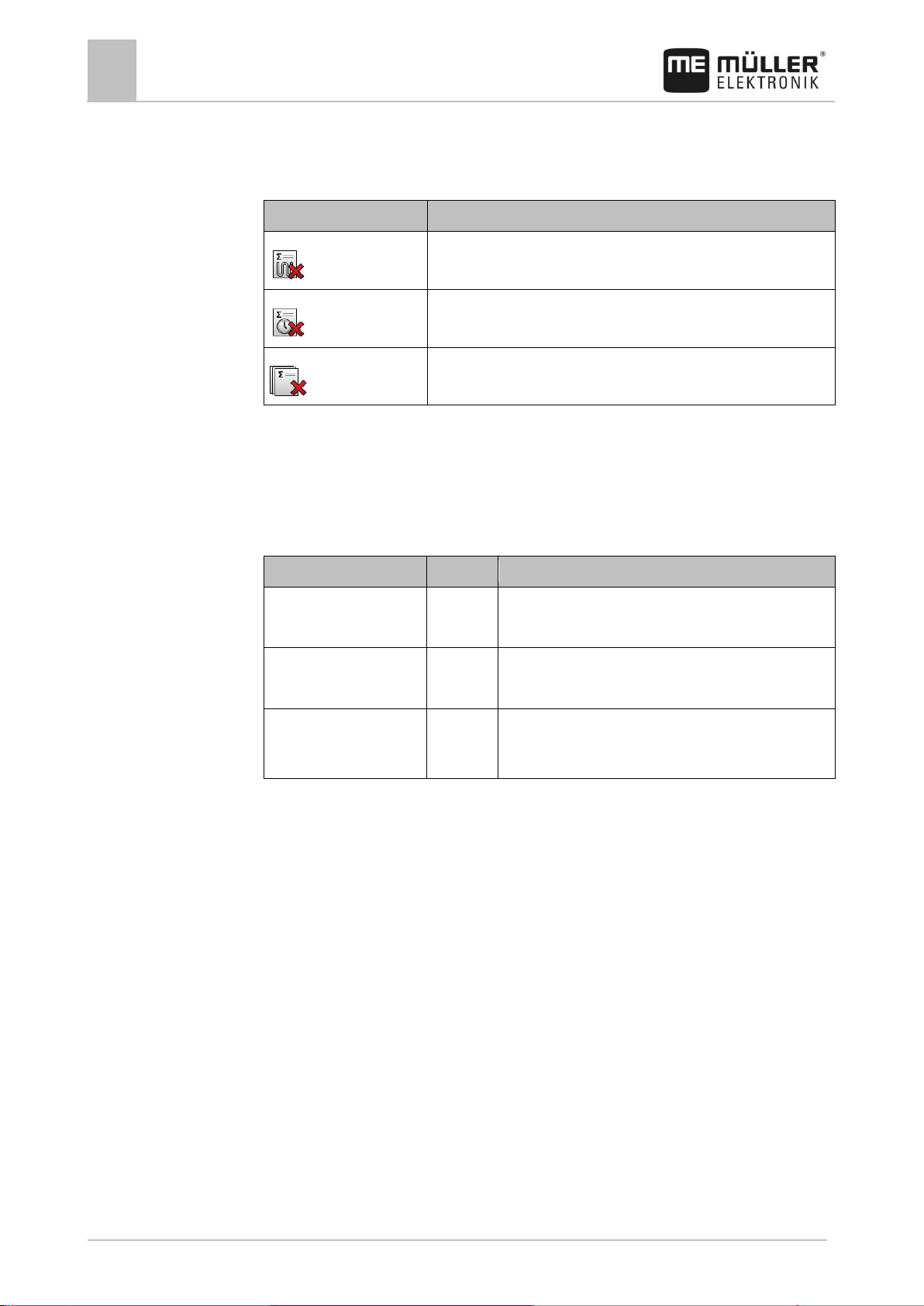
8
Tractor-ECU application
Results
58
V5.20170221
31302713-02-EN
Icon
This counter will be erased
Applied distance
Working time
All trip counters
Counter designation
Unit
This is documented
Distance
km
Distance during which the work position sensor was
activated.
Time in working position
h
Time during which the work position sensor was
activated.
Working position
0/1
0 = not in working position
1 = in working position
8.4.2
2. Tap "Information".
⇨ The "Results" screen appears with the trip counters.
3. Tap the function icons to clear the trip counters.
Task-related counter
These counters are transmitted to the ISOBUS-TC app. You can activate the counters in a task, and
they will then appear in the additional window as soon as the ISOBUS-TC App is minimized.
Task-related counter
Page 59
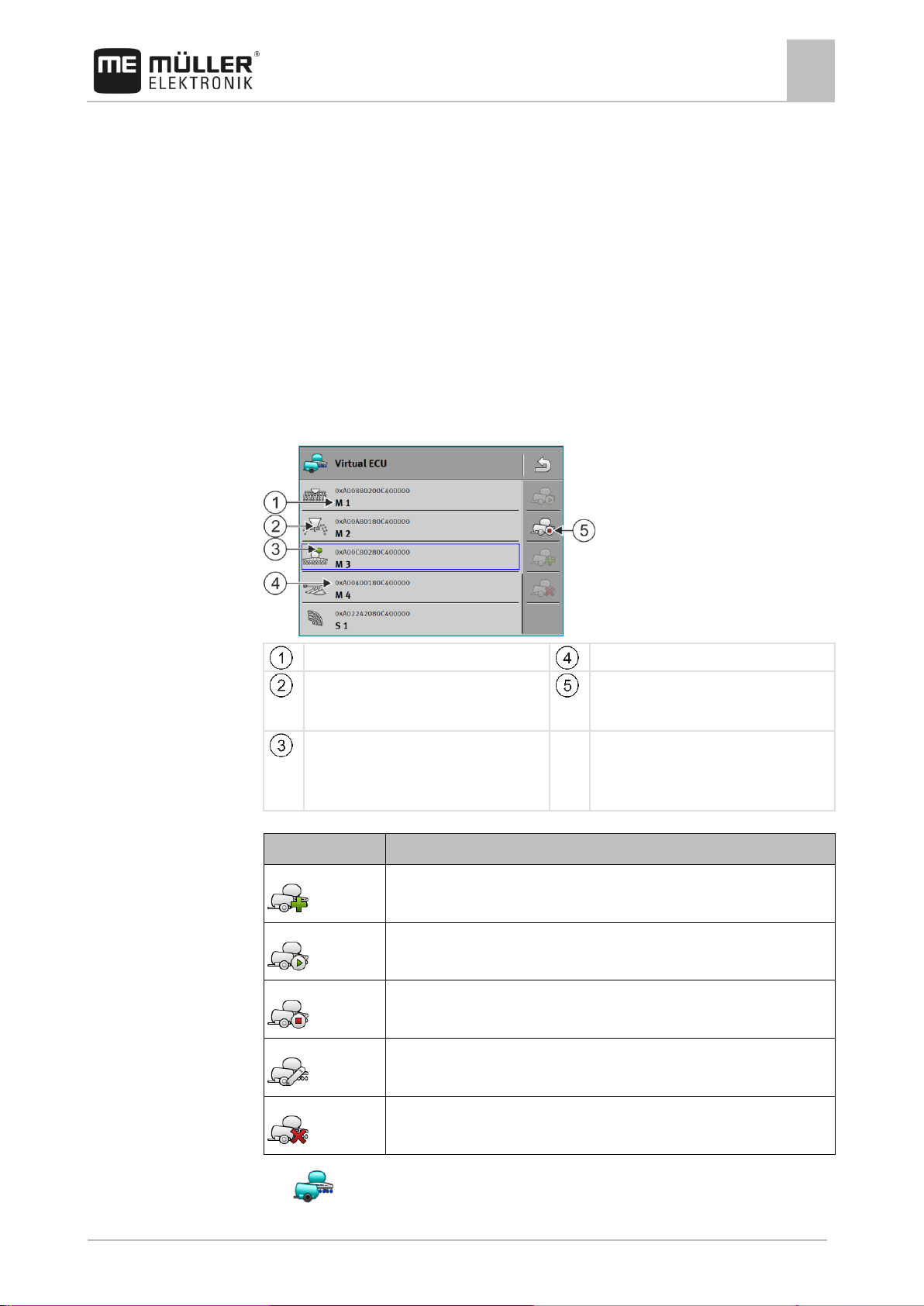
Virtual ECU application
Managing virtual job computers
9
31302713-02-EN
V5.20170221
59
Name of the virtual job computer
ISO name of the virtual job computer
Implement type
Function icons.
If at least one virtual job computer is activated,
only the stop icon appears.
State of the virtual job computer:
Green = Profile is activated;
Yellow = Profile will be activated after
restarting the terminal.
Function icon
Function
Creates a new job computer.
Activates the marked job computer.
Deactivates the job computer.
Calls up the parameters stored in the virtual job computer.
Deletes the job computer.
9
9.1
Procedure
Virtual ECU application
The Virtual ECU application (or for short: VECU) is used to create virtual job computers for the
following implements:
▪ Implements that do not have their own job computer. For example: Cultivators, ploughs,
mechanical seeders, etc.
▪ Machines that are operated using an on-board integrated display/controller connected to the
serial interface.
▪ Crop protection sensors that are connected serially to the terminal.
Each virtual job computer contains the most important features of the respective machine (working
width, geometry, type of on-board integrated display/controller) and provides these to other
applications if required.
Managing virtual job computers
1. - Open the "Virtual ECU" app.
Page 60

9
Virtual ECU application
Parameters
60
V5.20170221
31302713-02-EN
9.2
2. Tap "Settings".
⇨ The existing virtual job computers appear.
⇨ If a job computer is activated, most of the other function icons are greyed-out.
3. A maximum of five job computer profiles can be displayed on one page. To view other profiles,
swipe across the screen with your finger from bottom to top.
4. To edit a job computer profile or to create a new one, you must deactivate the activated job
computer profile.
Parameters
Name
Name of the virtual job computer.
External Controller
If you have connected an on-board integrated display/controller or crop protection sensor to the serial
interface, you must select the model in this parameter.
The list contains the following devices:
▪ On-board integrated display/controllers that can communicate using one of the protocols ASD or
LH5000 and are capable of communicating with the terminal. If you want to connect an on-board
integrated display/controller that supports this protocol, but does not appear in the list, please
contact Müller-Elektronik.
▪ Crop protection sensors that can be connected to the serial interface of the terminal.
Implement type
Use this parameter to define the type of implement.
The following implement types are available:
▪ Planter/seeder
▪ Fertilizer spreader
▪ Sprayer
▪ Soil tillage
Swath width
This parameter shows the working width set for an ag equipment.
No. of sections
Enter the number of sections that can be switched off on the implement. On a field sprayer, they are
the section valves; on a fertilizer spreader or a planter/seeder, they can be e.g. metering units.
This parameter serves to transmit the proper number of sections to the SECTION-View module, so
that you can switch the sections manually.
Each section appears as part of the working bar on the screen.
Page 61

Virtual ECU application
Parameters
9
31302713-02-EN
V5.20170221
61
Calls up the machine geometry.
A
Mounted:
Distance between the coupling point and the work point of the machine.
Trailed:
Distance between the coupling point and the pivot point of the machine.
For single-axle trailers, the pivot point is located at the centre of the axle, for tandem trailers between
two axles. For planters/seeders, cultivators and other soil tillage implements, the pivot point must be
determined individually.
B
Mounted:
Not available
Trailed:
Distance between the pivot point of the machine and the work point.
C
Only for spreaders: Working Length
D
Lateral offset
If the mounted implement is offset to the left in the direction of travel, enter a negative value. For
example: - 50 cm.
Sections
Opens a screen where you can enter the width of the individual sections on the implement.
Machine model
This parameter influences how the working bar follows the arrow in TRACK-Leader. The
configuration improves the precision of the recording of applied areas in curves.
After each change, you also need to adjust the geometry.
Possible values:
▪ "mounted"
Setting for implements that are mounted on the tractor three-point hitch.
▪ "trailed"
Settings for implements trailed by a tractor. The working bar is guided like a trailer behind a
tractor.
Geometry
The geometry contains a series of dimensions that help to properly display the vehicle-implement
combination in TRACK-Leader and determine its position.
To call up the geometry, tap the function icon:
Screen for entering the geometry for different machine models
Page 62

9
Virtual ECU application
Work screen
62
V5.20170221
31302713-02-EN
Mounted fertilizer spreader
Trailed sprayer
Display in TRACK-Leader
9.3
Geometry of machines and display in TRACK-Leader
Work screen
The following information may appear on the work screen:
▪ Serially transmitted application/spread rates: Target rates and current rates
▪ Section status and number
▪ Implement geometry
Page 63

ISOBUS-TC task processing
Configuring ISOBUS-TC
10
31302713-02-EN
V5.20170221
63
10
10.1
10.1.1
10.1.2
ISOBUS-TC task processing
The ISOBUS-TC application has two jobs:
▪ As Task Controller, the application controls all of the relevant data between the terminal and
other implements that are connected to the ISOBUS or terminal (Part 11 of the standard
ISO11783).
▪ As Task Manager, the application enables the creation and editing of ISO-XML tasks. This also
enables communication with Farm Management Information Systems (Part 10 of the standard
ISO11783).
ISOBUS-TC as Task Controller
The jobs performed by the application depend on how the "Operating Mode" parameter is configured.
▪ "Standard" - Only the Task-Controller jobs
▪ "Extended" - Task-Controller and Task-Manager jobs
Configuring ISOBUS-TC
The "farmpilot" parameter
This parameter shows the status of the connection to the "farmpilot" portal.
“Operating Mode” parameter
With this parameter, you can set whether the Task Controller of ISOBUS-TC should work in the
background or if you want to work actively with ISO-XML tasks.
▪ "Standard" - Two working methods are possible here.
Working method 1:
– All task data is managed through the "TRACK-Leader" app.
– In ISOBUS-TC, you cannot create any tasks.
– In this operating mode, ISOBUS-TC works in the background.
Working method 2:
– You can load field data from a shape file (field boundaries, guidance lines) in ISOBUS-TC.
This field data is made available in the "TRACK-Leader" app. Also possible without an
ISOBUS-TC license.
Page 64
10
ISOBUS-TC task processing
Configuring ISOBUS-TC
64
V5.20170221
31302713-02-EN
Procedure
10.1.3
10.1.4
– After activating the ISOBUS-TC license, you can edit shape prescription maps.
– In ISOBUS-TC, you cannot create any tasks.
▪ "Extended" - In this operating mode, the ISOBUS-TC menu is extended. The ISOBUS-TC
license is required. In this mode, ISOBUS-TC serves to manage and process ISO-XML tasks.
Two working methods are possible here.
Working method 1:
– You can manage and process ISO-XML tasks using a Farm Management Information
System.
Working method 2:
– You can create and manage master data yourself in the ISOBUS-TC app.
In these instructions, only the standard mode will be explained. The extended mode is described in
the separate instructions for ISOBUS-TC.
1. - Open the ISOBUS-TC application.
2. Tap "Settings".
3. Tap "Operating Mode".
4. Tap "Extended" if you want to work with tasks. Tap "Standard" to be able to work without tasks.
5. - Confirm.
⇨ You will be asked whether you want to change the setting.
6. Tap "Yes" if you want to confirm this.
⇨ All data will be saved and the operating mode will be switched.
7. Wait until all messages have faded out.
What happens with the data?
The data structure is different in the two operating modes. After changing the mode, the task and field
data will be saved. When switching again, the stored data will be loaded.
“TC number” parameter
Number of the Task-Controller. For complex systems with multiple terminals and Task-Controllers,
several Task-Controllers can be distinguished based on this number. If need be, you can control
which Task-Controller the connected job computer should communicate with.
“Prefer internal Tractor-ECU?” parameter
This parameter is important on vehicles that have their own Tractor-ECU in addition to the ME
terminal.
Activate the parameter if the GPS receiver is connected to the ME terminal or to the TRACK-Leader
AUTO steering system. Deactivate the parameter if the GPS receiver is connected to a different
terminal.
Page 65

ISOBUS-TC task processing
Configuring the list of connections
10
31302713-02-EN
V5.20170221
65
Tractor job computer icon In this case, it is the
Tractor-ECU application of the terminal.
ISO number for the ISOBUS job computer
There is a connection between "Tractor-ECU"
and "ME_ISO_Sprayer".
- connected implements.
Name of the job computer
Icon for the "ME_ISO_Sprayer " ISOBUS job
computer
Not all of the equipment in the list must be
connected. Job computers which contain no
relevant geometric data can be disconnected.
In the image, the "Tractor" job computer has
been disconnected, as the tractor geometry
should be transferred from the Tractor-ECU
application of the terminal.
- disconnected implements.
10.1.5
10.1.6
10.2
Procedure
"Save finished tasks as a file?" parameter
If this parameter is activated, all ISO-XML tasks are saved on the memory device as a text file.
“Validation of the device description” parameter
Optional parameter. Deactivated per default.
Please note that when the parameter is activated, Task-Controller version 3 is supported. If the
parameter is deactivated, Task-Controller version 2 is supported.
Only activate this parameter if you want to ensure that SECTION-Control and ISOBUS-TC only
communicate with AEF-compliant job computers.
Job computers that are not AEF-compliant are not supported by ISOBUS-TC in this case.
Configuring the list of connections
The list of connections indicates the ISOBUS job computers from which the terminal will load the
geometries of the connected implements. This geometry is required in order to calculate the position
of all implement components on the basis of the GPS signal. Only in this way are precise parallel
driving and section switching possible.
The farm equipment must be ordered consecutively from the front to the rear when viewed in the direction of
travel
If you are not using the ISOBUS-TC application, you can configure the list of connections as follows:
All ISOBUS job computers are connected to the ISOBUS.
Page 66

10
ISOBUS-TC task processing
Using fields and shp data
66
V5.20170221
31302713-02-EN
10.3
1. - Open the ISOBUS-TC application.
2. Tap "Current task".
⇨ The "Task" screen will appear.
3. Tap "List of connection".
⇨ You have called up the list of connections screen.
⇨ A list will appear with all of the equipment connected to the ISOBUS. The connectors
appear between the equipment.
4. Tap the task in the top row in order to select the first implement. If you are using a ME terminal to
which a GPS receiver is connected, insert the Tractor-ECU application in the top row. If another
terminal or tractor job computer contains the geometry, you can set it.
5. The device which is connected to the ME terminal should appear in the second line. Tap the line
with the second implement and select one from this.
6. You now only need to select the appropriate connector between the two devices. Tap the line
between two devices and select the appropriate connector for each device.
7. - Exit the screen to save the settings.
In simple systems, the terminal can set up the list of connections automatically. In particular, when
the ME terminal is the only unit containing the tractor geometry.
It can however still be necessary to set the list of connection manually in the following instances:
▪ If a tractor job computer (Tractor-ECU), in which the tractor geometry is saved, is mounted as an
independent job computer on the tractor. In this instance, you must decide which Tractor-ECU is
connected in the list of connections with other equipment: the application on the ME terminal or
on the tractor job computer.
▪ If the system cannot organize the ISOBUS job computer by itself. For example when more than
one implement is connected to the tractor (e.g.: slurry tanker and planter/seeder).
▪ When the connection to an ISOBUS job computer is interrupted during the start-up of a ISO-XML
task. In most cases, the list of connections will be set correctly as soon as you reconnect the
ISOBUS job computer.
▪ If this error message appears when starting the terminal: "List of connection is incomplete."
▪ When the following error message appears when starting a navigation in TRACK-Leader: "The
device data is still loading." The settings in the list of connections can eliminate this problem.
Using fields and shp data
In the "Fields" category, you can create all of the fields that you want to process. For each field, you
can enter the following properties:
▪ Field name
▪ Code (optional)
▪ Area
▪ Field boundary
▪ Guidance lines
▪ Obstacles
▪ Prescription map (ISOBUS-TC license required)
Page 67

ISOBUS-TC task processing
Using fields and shp data
10
31302713-02-EN
V5.20170221
67
Icon
Function
Creates a new field.
Activates the field.
Deactivates the field.
Enables editing of the field properties.
Deletes the field.
Icon only appears when you tap .
Enables the import of field data.
Displays the loaded prescription map.
Displays the imported field data.
Enables the export of field data.
Icon only appears when you tap .
Deletes the selected data.
Icon only appears when you tap .
10.3.1
Purpose
10.3.2
Procedure
What is field data for?
All field properties that are stored in this way can be used when working in TRACK-Leader. To do so,
you must activate the field to be processed in ISOBUS-TC before each navigation.
Creating fields
To create a new field:
1. - Open the ISOBUS-TC application.
2. Tap "Fields".
⇨ A list with already created fields appears. You can store various field data for each field. For
example: Field name, area, field boundary, prescription map and obstacles. You can access
this data when you work on the same field in the future.
Page 68

10
ISOBUS-TC task processing
Using fields and shp data
68
V5.20170221
31302713-02-EN
10.3.3
Procedure
3. - Create a new field.
⇨ A form for entering the data appears.
4. On the topmost line, enter a field name.
5. - Exit the screen.
⇨ You will be asked whether you want to save the changes.
6. Confirm.
⇨ A list of created fields appears. The new field appears at the bottom end. Each field is given a
clear PFD number. The fields are sorted according to these numbers. The numbers can be seen
in the field list above the respective field name. Moreover, you can see the number in the header
when you open the field.
PFD numbers
Each PFD number is only given one single time. Even if you delete a field, its PFD will not be used
again.
When processing the fields in TRACK-Leader, this number will also be assigned when saving the
field data in the ngstore database and attached to the field name.
Example:
Work performed on field PFD1 will be saved in TRACK-Leader under "ISOBUS-TC--1".
Work performed on field PFD50 will be saved in TRACK-Leader under "ISOBUS-TC--50".
Activating and deactivating fields
You can activate a field as follows:
In the "Virtual ECU" application, you have activated the virtual job computer for the implement to
be used or you have connected an ISOBUS job computer.
Operating mode of ISOBUS-TC: Standard
1. - Open the ISOBUS-TC application.
2. Tap "Fields".
⇨ A list with already created fields appears.
3. Tap the entry with the field to be processed.
4. - Activate the field.
5. - Open the TRACK-Leader application.
6. Start a new navigation.
⇨ The terminal loads all of the data from the storage: Field boundaries, guidance lines, tracks.
⇨ In doing so, the terminal also takes account of which job computer was used to process the
field. Therefore, if you work on the field two consecutive times with the field sprayer, the
tracks for the field sprayer will be loaded the second time. However, if you work on the field
with a fertilizer spreader, the tracks for the fertilizer spreader will be loaded.
Page 69

ISOBUS-TC task processing
Using fields and shp data
10
31302713-02-EN
V5.20170221
69
Procedure
10.3.4
Procedure
7. Depending on which machine you are working with, you can create or select a suitable guidance
line set in TRACK-Leader. More information on guidance line sets can be found in the
instructions for TRACK-Leader.
If you want to rework the field, you must go to the "Storage" menu in TRACK-Leader and delete the
tracks there with .
To finish the work:
The navigation screen is called up in TRACK-Leader.
You have worked the field in TRACK-Leader. On the screen, you can see the field with field
boundary, guidance lines and other field data.
1. - Terminate the navigation in TRACK-Leader.
2. - Open the ISOBUS-TC application.
3. Tap "Fields".
4. Tap the entry with the field that was just processed.
5. - Deactivate the field.
⇨ The field will be deactivated. In the process, it will also be saved with all of the current field
Importing field data (*.shp)
data. With the next activation, the data will be automatically loaded again.
To import field data:
The shp files are in WGS84 format.
1. Copy the field data to be imported to the SHP folder on the USB memory device.
2. Please insert the USB memory device.
3. - Open the ISOBUS-TC application.
4. Tap "Fields".
5. If you have not created a field yet, create a field. [➙ 67]
6. Tap the field for which you want to load the shp data.
⇨ The field properties appear. You can see the previously entered data and several function
icons on the side.
7. - Open the import view.
8. Tap "Data type".
⇨ A list with possible data types will appear.
9. Select the type of field data that you want to load.
10. Tap "File selection".
11. Select the file.
⇨ The field data is loaded.
Page 70

10
ISOBUS-TC task processing
Using fields and shp data
70
V5.20170221
31302713-02-EN
10.3.5
Procedure
10.3.6
10.3.7
Procedure
If you now activate the field, you can start a new navigation with the loaded field data.
Exporting field data
To export field data:
1. Please insert the USB memory device.
2. - Open the ISOBUS-TC application.
3. Tap "Fields".
⇨ A list with already created fields appears.
4. Tap the field for which you want to export data.
⇨ The field properties appear. You can see the previously entered data and several function
icons on the side.
5. - Open the field view.
6. - Open the list with all field data.
7. - Export the field data.
Data on the memory device
During work with TRACK-Leader, two types of data are produced:
▪ Tracks - Everything that is marked in green on the screen. This data describes one single work
process.
– The tracks are automatically saved in TRACK-Leader as soon as the field is deactivated in
ISOBUS-TC.
– You are in the "ngstore" folder on the USB memory device.
– They could be imported for evaluation with TRACK-Guide Desktop.
– Each field is given the name ISOBUS-TC--PFD. Whereby PFD stands for the PFD number
of the field in ISOBUS-TC. For example: ISOBUS-TC--2
▪ Changing of fixed field data: Field boundaries, guidance lines, obstacles. This data is not only
important for one work process, it can also be used in the future.
– This data is saved as shp files in the "SHP" folder.
Transferring field data to a different terminal
To transfer all field data to a different terminal:
Operating mode of ISOBUS-TC: Standard
1. Terminal 1: Export all field data to a USB memory device. [➙ 70]
2. Terminal 2: Create the field profiles once again. [➙ 67]
3. Terminal 2: Import all field boundaries, guidance lines etc. from a USB memory device. [➙ 69]
Page 71

ISOBUS-TC task processing
Using prescription maps
10
31302713-02-EN
V5.20170221
71
10.4
10.4.1
Procedure
Using prescription maps
A prescription map is a detailed map of a field. In this map the field is split up into areas. The
prescription map contains information on how the product(s) are to be applied in each area of the
field.
When the prescription map has been loaded, the terminal checks via GPS coordinates of the vehicle
what application rates are needed according to the prescription map and transfers this information to
the appropriate ISOBUS job computer.
The terminal can open prescription maps in two formats:
▪ Shape format (*.shp)
– The ISOBUS-TC app is used to open a prescription map in shape format.
– Multiple prescription maps can be imported.
– Only one prescription map can be used at a time.
▪ ISO-XML format
– The prescription map must be added to an ISO-XML task on a PC.
– The prescription map can only be used in combination with an ISO-XML task through the
ISOBUS-TC application.
– The format is supported by all ISOBUS job computers, regardless of their manufacturer.
– Up to four prescription maps can be used simultaneously in one task. This way, for
implements that have more than one metering system, you can use a prescription map for
each system. Prerequisite: MULTI-Control license. The procedure is described in the
MULTI-Control II instructions.
Importing shape prescription maps
You can import more than one prescription map for a field.
To import a prescription map:
The ISOBUS-TC license must be activated.
1. Copy a shape prescription maps to the "SHP" folder on the USB memory device.
2. Please insert the USB memory device.
3. - Open the ISOBUS-TC application.
4. Tap "Fields".
5. If you have not created a field yet, create a field. [➙ 67]
6. Tap the field for which you want to load the prescription map.
⇨ The field properties appear. You can see the previously entered data and several function
icons on the side.
⇨ If a prescription map has already been activated for this field, its name will appear on the
"Prescription map" line. You can still import another one.
7. - Open the import view.
Page 72

10
ISOBUS-TC task processing
Using prescription maps
72
V5.20170221
31302713-02-EN
10.4.2
Procedure
10.4.3
Procedure
8. Tap "Data type".
⇨ A list with possible data types will appear.
9. Select "Prescription map".
10. Tap "File selection".
11. Select the prescription map.
⇨ The screen with the properties of the prescription map appears.
12. When a prescription map is imported for the first time, first tap "Column selection" to choose the
column with the target rates, then tap "Unit selection" to choose the units. For future imports,
these values will be automatically selected.
13. - Exit the screen.
14. The overview image of the prescription map appears.
15. - Exit the screen.
16. You will be asked whether you want to import the file.
17. Confirm.
18. The prescription map will be loaded and activated.
Selecting shape prescription maps
You can import a multitude of prescription maps for each field. Before starting operation, you must
activate the right prescription map.
To activate a prescription map:
You have imported several prescription maps.
1. - Open the ISOBUS-TC application.
2. Tap "Fields".
3. Tap the field that you want to work on.
⇨ The field properties appear.
⇨ If a prescription map has already been activated for this field, its name will appear on the
"Prescription map" line.
4. Tap "Prescription map".
5. Select a prescription map.
⇨ When you activate the field, this prescription map will be used.
Editing shape prescription maps
After importing the prescription map, you can:
▪ Change all values by a certain percentage point.
▪ Change selected values by an absolute number.
To change all of the values at once:
Page 73

ISOBUS-TC task processing
MULTI-Control
10
31302713-02-EN
V5.20170221
73
Procedure
10.4.4
10.5
1. - Open the ISOBUS-TC application.
2. Tap "Fields".
3. Tap on the field to be edited.
4. Tap .
5. Tap .
6. Enter the desired change in value. For example: 50% = halve, 200% = double
7. - Confirm.
⇨ The "Prescription maps" screen appears.
⇨ All values have been changed.
⇨ - Exit the screen to save the changes.
To change a selected value:
1. - Open the ISOBUS-TC application.
2. Tap "Fields".
3. Tap on the field to be edited.
4. Tap .
5. In the column with the target rates (left), tap the value that you want to change.
⇨ The keyboard appears.
6. Enter the new value.
7. - Confirm.
⇨ The "Prescription maps" screen appears.
⇨ The new value appears in the cell you have changed.
8. - Exit the screen to save the changes.
ISO-XML prescription maps
Prescription maps in ISO-XML format are created in an electronic Farm Management Information
System and are transmitted to the terminal with an ISO-XML task.
The ISOBUS-TC license is required to edit them.
Working with ISO-XML tasks is described in the instructions for ISOBUS-TC.
MULTI-Control
After activating the MULTI-Control license, you can use the ISOBUS-TC app to assign multiple
prescription maps to a machine.
Page 74

10
ISOBUS-TC task processing
MULTI-Control
74
V5.20170221
31302713-02-EN
Function
Operating Mode: Standard
Operating Mode: Extended
MULTI-Product
not possible
possible
MULTI-Rate
possible
possible
This is necessary in two cases:
▪ MULTI-Rate - If the machine applies only one product that is metered by several metering units.
For example, a field sprayer with two tanks and two control manifolds.
▪ MULTI-Product - If the machine has several tanks that are used to apply different products at
different rates. For example: Planter/seeder with liquid fertilizer.
MULTI-Control is described in separate operating instructions.
Operating modes
Page 75

File Server application
11
31302713-02-EN
V5.20170221
75
11
Procedure
File Server application
The File Server application is used to define a save location on the terminal. This save location can
be used by all ISOBUS implements which do not have their own USB interface. This enables the
updating of certain ISOBUS job computers, and also the possibility of saving, for example protocols
or error messages.
A "Fileserver" folder is created for this purpose on the hard disk of the terminal. All ISOBUS
implements can access this folder, and write or read data there.
The folder has a maximum disk space of 5 MB.
If you want to copy files to the terminal, they must be on your USB memory device, in the
"Fileserver" folder.
The "File Server" plug-in is activated.
1. - Open the File Server application.
⇨ The application start screen will appear.
2. Tap "Storage".
3. - Copy files from the USB memory device onto the terminal (Import).
4. - Copy files from the SD card in the terminal to the USB memory device (Export).
⇨ One of the following messages will appear: "Start import?" or "Start export?".
5. To confirm, tap "Yes".
⇨ The data will be copied.
⇨ Here is an overview of the folders on the USB memory device: Folders on the USB memory
device [➙ 27]
⇨ A report will appear.
6. To confirm, tap "OK".
⇨ You have successfully imported or exported the data.
Page 76

12
Technical specifications
Technical specifications of the terminal
76
V5.20170221
31302713-02-EN
Operating voltage
10V - 32V
Power consumption
(operation)
0.5A (typical) - 4A
Power input
Typical: 6W
Maximum: 40W
Ambient temperature
-20°C - +60°C
Storage temperature
-30°C - +80°C
Dimensions (W x H x D)
243mm x 186mm x 69mm
Weight
1.1kg
Protection class
IP6K4 according to ISO 20653:2013
EMC
ISO 14982
ESD protection
ISO 10605:2001 Level IV
Environmental testing
Vibration:
ISO 15003 Level 1 with Level 2 temperature overlap in accordance
with ISO 15003
Shock:
100 shocks per axis and direction with 15g and 11ms in accordance
with IEC 60068-2-27
Processor
i.MX 515 600MHz
Coprocessor
STM32F205
Storage
256M mDDR
Bootflash
128M SCL-NAND-Flash
Operating system
WinCE 6.0
Display
8" SVGA TFT
Housing
PC-ABS
Inputs / outputs
1 x USB
1 x Sub-D 9 socket (CAN and power supply)
12
12.1
Technical specifications
Technical specifications of the terminal
Page 77

Technical specifications
Assignment plans
12
31302713-02-EN
V5.20170221
77
1 x Sub-D 9 plug
1 x Sub-D 9 plug (CAN & signals)
1 x M12 (camera)
1 x M12 (Industrial Ethernet)
Pin
Signal name
Function
1
CAN_L
CAN_L out
6
-Vin
Supply ground
2
CAN_L
CAN_L in
7
CAN_H
CAN_H in
3
CAN_GND
CAN ground, internally connected to the ground
8
CAN_EN_out
Switched input voltage, ≤ 250mA
4
CAN_H
CAN_H out
9
+Vin
Supply
5
Ignition
Ignition signal
Screen
Screen
ESD/EMC shielding
12.2
12.2.1
12.2.2
Assignment plans
Port A (CAN bus)
9-pin Sub-D socket
Port B
9-pin Sub-D connector
Page 78

12
Technical specifications
Assignment plans
78
V5.20170221
31302713-02-EN
Purpose
Pins used
As second CAN interface
7, 9
As second serial interface
2, 3, 4, 5
As signal input for two digital and one analogue
signal.
1, 5, 6, 8
Pin
Signal name
1
Wheel sensor1
6
PTO2
2
/RxD2
7
CAN2_H
3
/TxD2
8
Working position sensor3 or
Reverse signal for determining the course
4
Voltage supply for GPS receiver
Switched input voltage, ≤ 250mA
9
CAN2_L
5
GND
Screen
ESD/EMC shielding
12.2.3
Port B is a 9-pin Sub-D connector.
The connector can be used for the following purposes depending on its assignment:
Legend:
1
) Digital input as per: ISO 11786:1995 chapter 5.2
2
) Digital input as per: ISO 11786:1995 chapter 5.3
3
) Analog input as per: ISO 11786:1995 chapter 5.5
Port C
9-pin Sub-D connector
Page 79

Technical specifications
Assignment plans
12
31302713-02-EN
V5.20170221
79
Pin
Signal name
Function
1
(DCD1)
Switched input voltage, ≤ max. 250 mA total (Pin 1
+ Pin 4)
6
DSR
DSR
2
/RxD
/RxD
7
RTS
RTS 3 /TxD
/TxD
8
CTS
CTS
4
(DTR)
Switched input voltage, ≤ max. 250 mA total (Pin 1
+ Pin 4
9
(RI)
5 V ≤ 250 mA
5
GND
Signal ground
Electromagnetic
shielding
Electromagnetic shielding
ESD/EMV shielding
Pin
Signal name
Function
1
Power
Voltage supply, max. 250mA
2
Supply ground
Supply ground
3
FBAS2
Camera
4
FBAS
Camera
5
Signal ground
Signal ground
6
Screen
ESD/EMC shielding
12.2.4
CAM port
M12 socket: Camera
Page 80

12
Technical specifications
Licence conditions
80
V5.20170221
31302713-02-EN
Pin
Signal name
Function
1
TD+
white-orange
2
RD+
white-green
3
TD-
orange
4
RD-
green
5
Pin not present
Pin not present
Screen
Screen
ESD/EMC shielding
12.2.5
12.3
ETH (Ethernet) port
M12 socket: Ethernet
Licence conditions
The software uses the following open source libraries:
▪ Eigen
http://www.mueller-elektronik.de/LICENCES/eigen/LICENSE.txt
▪ SpatiaLite
http://www.mueller-elektronik.de/LICENCES/spatialite/LICENSE.txt
▪ Proj.4
http://www.mueller-elektronik.de/LICENCES/proj.4/LICENSE.txt
▪ Expat
http://www.mueller-elektronik.de/LICENCES/expat/LICENSE.txt
▪ WCELIBEX
http://www.mueller-elektronik.de/LICENCES/wcelibex/LICENSE.txt
▪ Agg
http://www.mueller-elektronik.de/LICENCES/agg/LICENSE.txt
▪ Poco C++
http://www.mueller-elektronik.de/LICENCES/poco/LICENSE.txt
▪ QT
http://www.mueller-elektronik.de/LICENCES/qt/LICENSE.txt
▪ Boost
http://www.mueller-elektronik.de/LICENCES/boost/LICENSE.txt
Page 81

History
V5.20170221
13
31302713-02-EN
V5.20170221
81
13
13.1
History
V5.20170221
New section
▪ Configuring the Bluetooth connection in the Connection Center [➙ 44]
▪ Crop protection sensors [➙ 44]
▪ Virtual ECU application [➙ 59]
▪ History [➙ 81]
Updated sections
▪ Basic safety instructions [➙ 7]
▪ Applications on the terminal [➙ 12]
▪ Initial start-up [➙ 20]
▪ Using a memory device [➙ 27]
▪ GPS receiver [➙ 29]
▪ Connecting the on-board integrated display/controller to the terminal [➙ 42]
▪ Basic settings [➙ 46]
▪ Enabling and disabling applications [➙ 48]
▪ Tractor-ECU application [➙ 51]
▪ ISOBUS-TC task processing [➙ 63]
Deleted sections
▪ Mounting the GSM antenna
▪ Serial Interface application
 Loading...