

Page 1
Installation and operat i ng instr uc ti ons
TRACK-Guide II
Version: V7.20141016
30302710-02-EN Read and follow these operating instructions.
Keep these operating instructions in a safe place for later
reference.
Page 2

Company details
Document
Copyright ©
Installation and operating instructions
Product: TRACK-Guide II
Document number: 30302710-02-EN
From software version: 04.10.04
Original language: German
Müller-Elektronik GmbH & Co.KG
Franz-Kleine-Straße 18
33154 Salzkotten
Germany
Phone: ++49 (0) 5258 / 9834 - 0
Fax: ++49 (0) 5258 / 9834 - 90
Email: info@mueller-elektronik.de
Homepage: http://www.mueller-elektronik.de
Page 3

1
For your safety
6
1.1
Basic safety instructio ns
6
1.2
Layout and meaning of warnings
6
1.3
User requirements
7
1.4
Intended use
7
1.5
EC declaration of conformity
7
2
About these Operating Instructions
8
2.1
Target group of these Operating Instru ctions
8
2.2
Layout of operating instructions
8
2.3
Layout of references
8
3
Product description
9
3.1
Performance description
9
3.2
Scope of delivery
10
3.3
Information on the nameplate
10
4
Mounting and installation
11
4.1
Mounting the terminal in the tractor cab
11
4.1.2
Mounting the GSM antenna
12
4.2
Connecting the terminal to voltage supply
13
4.3
Connecting the terminal to the ISOBUS
13
4.4
SIM card
14
4.4.1
Inserting the SIM card
14
4.5
Connecting the ISO printer to the terminal
15
4.6
Connecting the ME LightBar to the terminal
16
4.7
Connecting the on-board computer to the terminal
16
4.8
Connecting the GPS Receiver to the terminal
17
4.9
Connecting sensors to the terminal
18
4.10
Connecting the camera to the terminal
19
5
Basic control principles
21
5.1
Getting to grips with the controls
21
5.2
Initial start-up
22
5.3
Configuration sequence
23
5.4
Using the function keys
23
5.5
Restarting the terminal
24
5.6
Inputting data
25
5.7
Using two terminals
25
Contents
Contents
4.1.1 Terminal ports 12
30302710-02-EN V7.20141016 3
Page 4

6
Opening applications in the selection menu
27
6.1
Display layout in the selection menu
27
6.2
Opening applications
27
6.3
Segmentation of the display
28
7
Configuring the terminal in the Service application
30
7.1
Controls in the Service application
30
7.2
Icons in the Service application
31
7.3
Changing the language
31
7.4
Basic settings
32
7.5
GPS receiver
33
7.5.1
Activating the GPS receiver
34
7.5.2
Configuring the GPS receiver
35
RTK license for SMART-6L
38
7.8.1
Activating a camera
39
7.8.2
Operating the camera
40
7.9
Configuring the joystick button allocations
41
7.10
Adjusting the brightness for day or night mode
43
7.11
Enabling and disabling applications
44
7.12
Activating licenses for full versions of the software
45
7.13
Setting the purpose of the terminal
46
7.14
Deleting files from the USB flash drive
46
7.15
Deleting pools
47
7.16
Activating the "Diagnostics" function
48
7.17
Screenshots
49
7.17.1
Configuring the screenshots function
49
7.17.2
Creating screenshots
49
7.18
CAN-Trace settings
50
7.19
Configuring farmpilot
51
7.19.1
Activating farmpilot
51
7.19.3
Configuring the GPRS connection manually
53
7.19.4
Sending diagnostic data to the portal
54
7.20
Activating the ISO printer
55
8
Tractor-ECU application
56
8.1
Add a vehicle profile
57
8.2
Configuring the parameters for a vehicle profile
57
Contents
Parameters for the GPS receiver 36
7.6 Configuring the "GPS TILT-Mo dule" terrain comp ensa tion 38
7.7 Activating an external LightBar 39
7.8 Camera 39
7.16.1 Diagnostics 49
7.19.2 Configuring the connection with farmpilot 52
4 30302710-02-EN V7.20141016
Page 5

8.2.1
Calibrating the speed sensor
61
8.2.3
Entering the position of the GPS Receiver
63
For machines fitted with an ISOBUS job computer
64
8.3
Activating vehicle pro file s
65
9
ISOBUS-TC task processing
66
9.1
Using ISOBUS-TC
66
9.2
Adjusting how you use ISOBUS-TC
66
9.3
Configuring the list of connections
67
11
File Server application
73
12
Maintenance and servicing
74
12.1
Servicing and cleaning the terminal
74
12.2
Disposing of the unit
74
12.3
Instructions on retrofitting
74
12.4
Checking the software version
75
12.5
Technical specificat io ns
75
12.5.1
Technical specifications of the terminal
75
12.5.2
Pin assignment of port A
76
12.5.3
Pin assignment of port B
77
12.5.5
Pin assignment of camera ports 1 and 2
79
13
Notes
80
Contents
8.2.2 Configuring a working position sensor 62
10 Serial Interface application 69
10.1 Transfer target rates via LH5000 69
10.2 Switching sections and transferring target rates via ASD 70
12.5.4 Pin assignment of port C 78
30302710-02-EN V7.20141016 5
Page 6
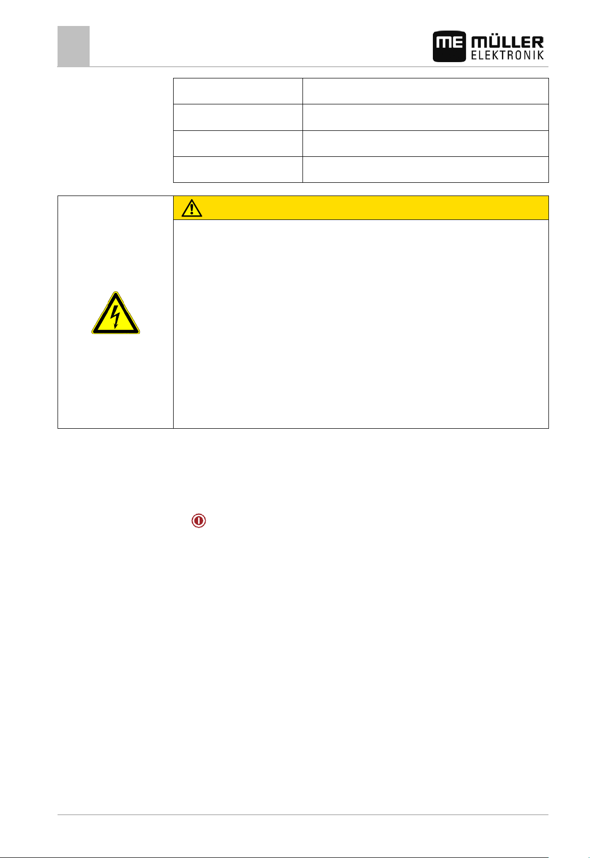
WARNING
physical injury, if not avoided.
1
1.1
1.2
For your safety
1
Basic safety instructions
For your safety
Basic safety instructions
Please read the following safety instructions carefully before using the product for the first time.
▪ Do not operate the terminal while driving in road traffic. Come to a standstill in order to use the
unit.
▪ Before maintaining or repairing the tractor, always disconnect the connection between the tractor
and the terminal.
▪ Before charging the tractor battery, always disconnect the connection between the tractor and
the terminal.
▪ Before welding on the tractor or implement, always disconnect the power supply to the terminal.
▪ Do not make any unauthorized modifications to the product. Unauthorized modifications or use
may impair safety and reduce the service life or operability of the unit. Modifications are
considered unauthorized if they are not described in the product documentation.
▪ Follow all recognized safety, industrial and medical rules as well as all road traffic laws.
▪ The product does not include any user serviceable parts. Do not open the casing.
▪ Read the operating instructions to the agricultural device which you want to control by using the
product.
Terminals with GSM modem
If the terminal is fitted with a built-in GSM modem, this will emit radio waves when it is switched on.
These can interfere with other equipment or be harmful to human health.
You should therefore follow the instructions below when the terminal is fitted with a GSM modem:
▪ If you wear a medical device, ask your doctor or the device manufacturer how to proceed in
order to prevent risks. Medical devices such as pacemakers or hearing aids may be sensitive to
the radio signal of the built-in GSM modem.
▪ If you wear a pacemaker, keep the terminal away from the pacemaker.
▪ Switch off the terminal as soon as you are close to a gas station, chemical plant, biogas plant or
any other location where combustible gases or fumes may be present. These gases can be
ignited by a spark and explode.
▪ Always maintain a distance of at least 20 cm between the GSM antenna and your body.
▪ Never switch the terminal on in an aircraft. Make sure that it is not accidentally switched on
during flight.
▪ Never connect the terminal by means of a power supply to the mains network. Only use the
vehicle battery.
Layout and meaning of warnings
All safety instructions found in these Operating Instructions are composed in accordance with the
following pattern:
This signal word identifies medium-risk hazards, which could potentially cause death or serious
6 30302710-02-EN V7.20141016
Page 7
CAUTION
physical injury or damage to property, if not avoided.
NOTICE
optimum work results.
Example
1.3
1.4
1.5
For your safety
User requirements
1
This signal word identifies low-risk hazards, which could potentially cause minor or moderate
incorrectly.
These actions require that you operate in a precise and cautious manner in order to produce
There are some actions that need to be performed in several steps. If there is a risk involved in
carrying out any of these steps, a safety warning will appear in the instructions themselves.
Safety instructions always directly precede the step involving risk and can be identified by their bold
This signal word identifies actions which could lead to operational malfunctions if performed
font type and a signal word.
1. NOTICE! This is a notice. It warns that there is a risk involved in the next step.
2. Step involving risk.
User requirements
▪ Learn how to operate the terminal correctly. The terminal must not be operated by anyone who
has not read the Operating Instructions.
▪ Please read and carefully observe all safety instructions and warnings contained in these
Operating Instructions and in the manuals of any connected vehicles and farm equipment.
Intended use
The terminal is intended exclusively for use in agriculture as well as in wine-growing, fruit-cultivating,
and hop-growing operations. The manufacturer cannot be held responsible for any installation or use
of the terminal that deviates from or exceeds the scope of intended use.
The manufacturer cannot be held liable for any personal injury or property damage resulting from
such improper use. All risks involved in engaging in improper usage, lie solely with the user.
Intended use also includes compliance with the conditions for operation and repairs prescribed by the
manufacturer.
The manufacturer cannot be held liable for any personal injury or property damage resulting from
such non-compliance. All risk arising from improper use lies with the user.
All applicable accident prevention regulations and all other generally recognized safety, industrial,
and medical standards as well as all road traffic laws must be observed. Any unauthorized
modifications made to the equipment will void the manufacturer's warranty.
EC declaration of conformity
This product has been manufactured in conformity with the following national and harmonised
standards as specified in the current EMC Directive 2004/108/EC:
▪ EN ISO 14982
30302710-02-EN V7.20141016 7
Page 8
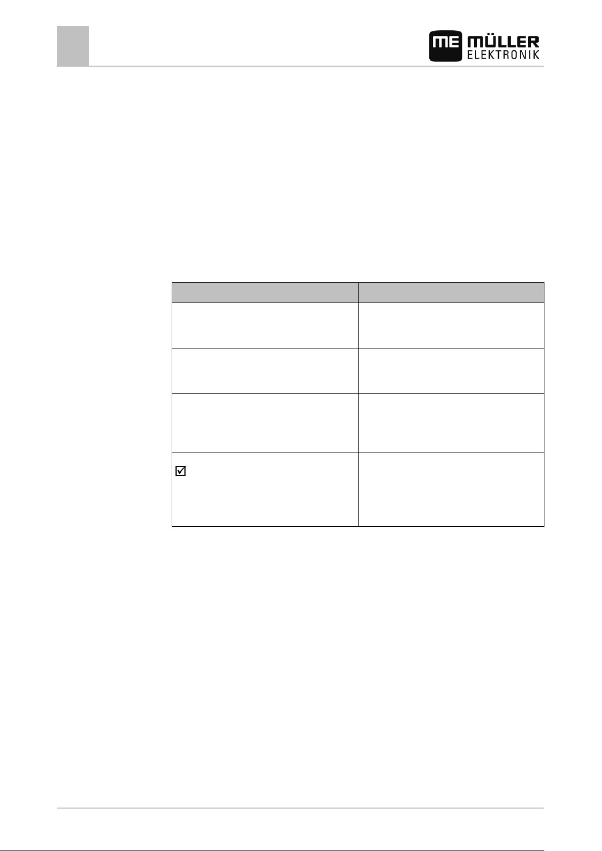
Type of depiction
Meaning
2.
⇨
This will happen when you perform an action.
⇨
steps.
can be performed.
2
2.1
2.2
2.3
About these Ope rating Instruc tions
2
Target group of these Operating Instructions
About these Operating Instructions
Target group of thes e Ope r a t i ng Instructions
These Operating Instructions are intended for personnel entrusted with installing and operating the
terminal.
Layout of operating instructions
The operating instructions explain step by step how you can perform certain operations with the
product.
We use the following symbols throughout these Operating Instructions to identify different operating
instructions:
1.
Actions that must be performed in succession.
Result of the action.
Result of an operating instruction.
This will happen when you have completed all
Requirements.
In the event that any requirements have been
specified, these must be met before an action
Layout of references
If any references are given in these Operating Instructions, they will appear as:
Example of a reference: [➙ 8]
8 30302710-02-EN V7.20141016
References can be identified by their square brackets and an arrow. The number following the arrow
shows you on what page the chapter starts where you can find further information.
Page 9

3
3.1
Software
Product description
Product description
Performance description
3
Hardware
Performance description
The terminal is available in two hardware versions:
▪ With GSM modem and with camera connections
– Complete functionality:
– It is the prerequisite for work with the farmpilot portal;
– On the rear side you can find two camera connections and one connection for the GSM
antenna.
▪ Without GSM modem and without camera connections
You can find out the terminal version you have on the connections on the terminal rear side. [➙ 12]
All applications of Müller-Elektronik available are installed on the terminal. But first you must activate
some of them.
See also: Activating licenses for full versions of the software [➙ 45]
The following applications are activated:
▪ SERVICE – this application configures the terminal.
▪ TRACK-Leader – a modern system enabling the driver of an agricultural vehicle keep exact
parallel lanes on the field.
▪ Tractor-ECU - this application enables you to configure all sensors connected to the terminal and
to input the position of the GPS receiver.
▪ File Server - This application is used to define a save location on the terminal. This save location
can be used by all ISOBUS implements which do not have their own USB interface.
▪ Serial Interface - This application enables a data exchange between the terminal and an on-
board computer via the serial interface. In this way, you can also use the GPS signal for
machines which are not ISOBUS-compatible. You can transfer target rates to the on-board
computer or switch sections. The data is sent using the LH5000 or ASD protocols.
– If you want to use the ASD protocol, you must activate the "ASD-Protocol" license.
You can test the following application for 50 hours free of charge:
▪ SECTION-Control – automatic boom section switching. Additional module for TRACK-Leader.
▪ VARIABLE RAT E-Cont. – with this application you can work with prescription maps saved as
shp files. Additional module for TRACK-Leader.
▪ TRACK-Leader TOP – automatic steering. Additional module for TRACK-Leader.
▪ FIELD-Nav – this is the first navigation software that contains all navigable paths, takes
movement restrictions into account and leads directly to the field or other agricultural destination.
The following applications are installed, but deactivated until you have activated a license:
▪ ISOBUS-TC – this is the certified ISOBUS task controller from Müller Elektronik. In this
application you can use the terminal for processing all tasks previously planned on the PC.
▪ ISOBUS-UT - interface for controlling ISOBUS job computers. As soon as this application is
activated, the terminal complies with the ISOBUS standard ISO 11783. It can then be used as an
ISOBUS terminal (UT) on all implements that meet the requirements of this ISOBUS standard,
regardless of the manufacturer.
If you also want to operate ISOBUS job computers with the terminal, you must activate this
application.
30302710-02-EN V7.20141016 9
Page 10
Abbreviation
Meaning
Hardware version
The terminal may only be connected to voltages within this range.
will be shown here.
3.2
3.3
Product description
3
Scope of delivery
Scope of delivery
The following items are included in delivery:
▪ Terminal
▪ Installation and Operating Instructions
▪ Operating instructions for the TRACK-Leader application - as a separate document.
▪ Bracket for mounting the terminal
▪ USB flash drive
▪ Base console for mounting the terminal.
▪ Voltage supply cable.
▪ DGPS receiver
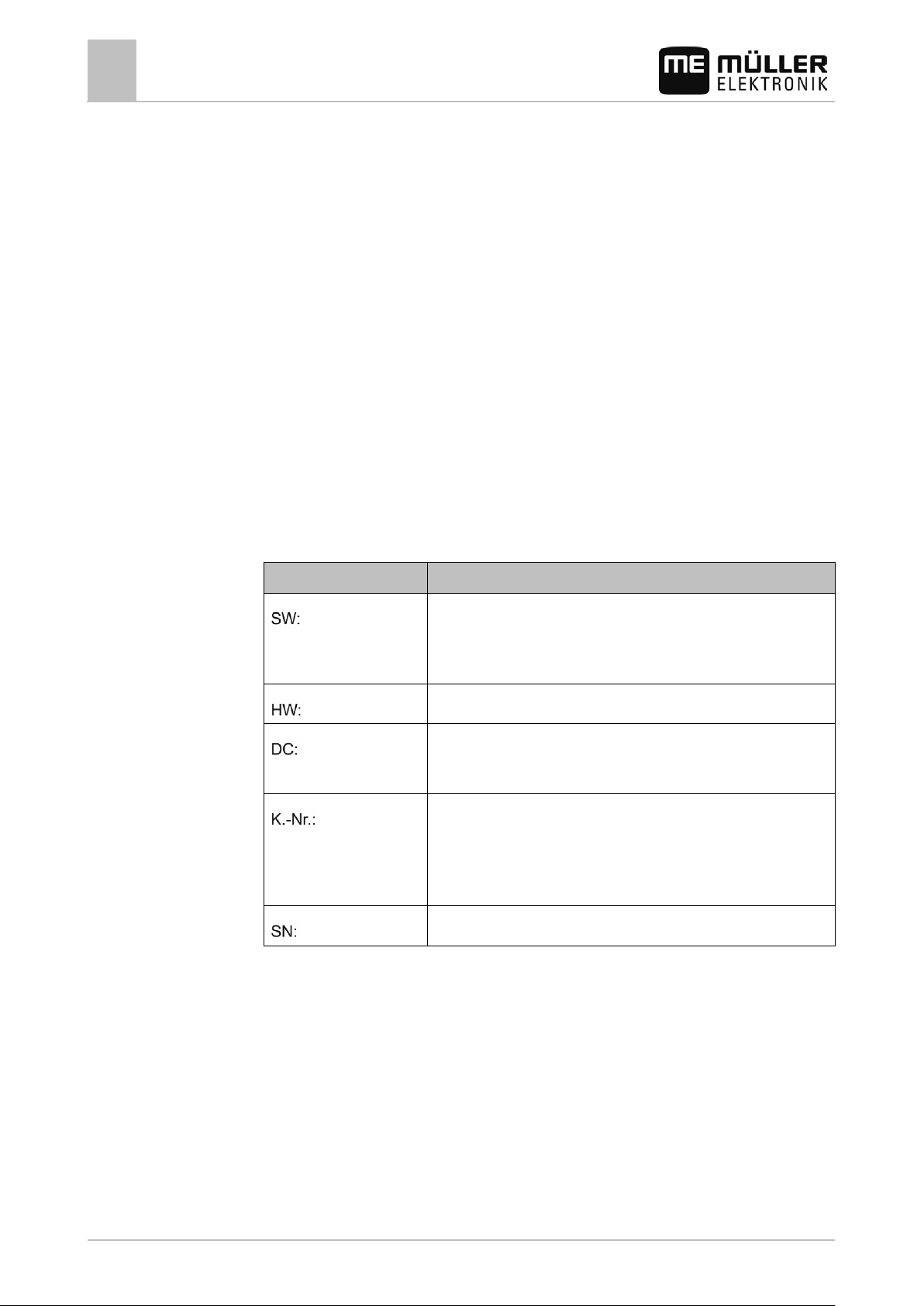
Information on the nameplate
You will find a nameplate sticker on the back of the terminal. On this sticker, you can find all the
information you need to definitively identify the product.
Have these details ready when you contact Customer Services.
Abbreviations on the rating plate
Software version
You can see the installed software version on the Start Screen of the
Service application:
Operating voltage
Customer number
If the terminal was manufactured for an agricultural machinery
manufacturer, the agricultural machinery manufacturer's item number
Serial number
10 30302710-02-EN V7.20141016
Page 11
NOTICE
◦ Mount the terminal at least 1 m away from the radio antenna or from a radio device.
4
4.1
Procedure
Mounting and installation
Mounting the terminal in the tractor cab
4
Mounting and installation
Mount the terminal and all additional components in the following order:
1. Mount the terminal in the tractor cab. [➙ 11]
2. Connect the terminal to the voltage supply (port A). [➙ 13]
3. Connect the terminal to the GPS receiver (port C). [➙ 17]
4. Connect the working position sensor (optional, port B). [➙ 18]
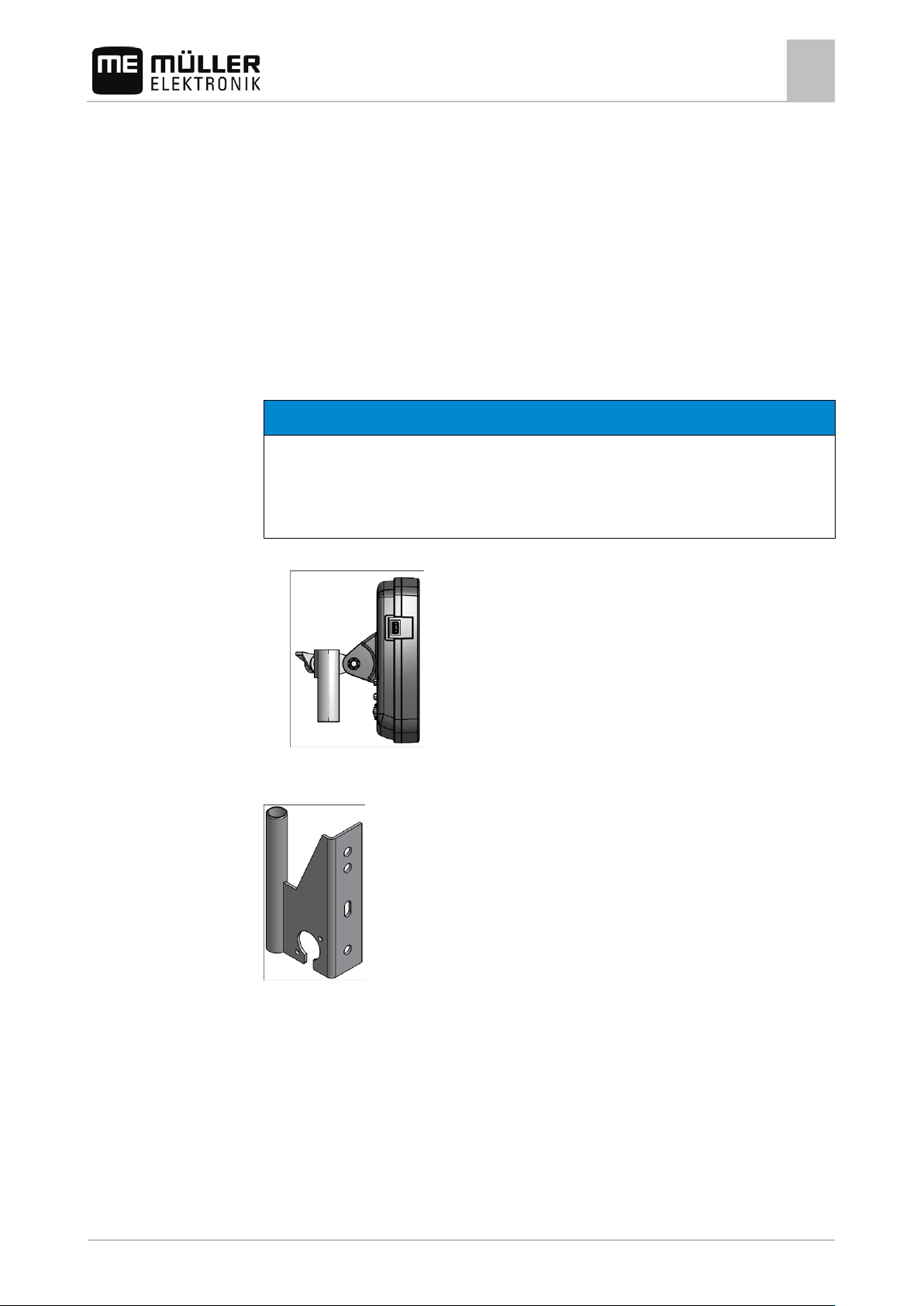
Mounting the terminal in the tractor cab
Electromagnetic interference
The operation of the terminal may be impaired by electromagnetic waves emitted by other farm
equipment.
1. Screw the bracket to the terminal.
2. Mount the terminal with the bracket installed inside the tractor cab.
For instance, you can use the ME base console for this purpose.
Base console
30302710-02-EN V7.20141016 11
Page 12
installed.
installed.
- LightBar
voltage supply with TRACK-Guide II.
installed.
WARNING
between the driver and the GSM antenna.
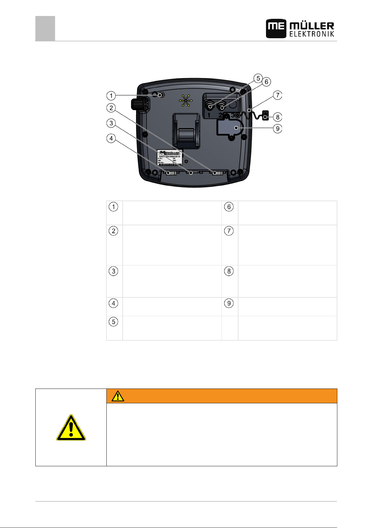
4.1.1
Mounting and installation
4
Mounting the terminal in the tractor cab
Terminal ports
Rear of the terminal. Version with a GSM modem and camera connections
GSM antenna port
Only for terminals with a GSM modem
Port for analog camera
Only for terminals with a GSM modem
4.1.2
Port C
Serial port RS232 for:
USB port
USB 1.1
- GPS receiver
- Terrain Compensation "GPS TILT-Module"
Port A
CAN bus port
Covering cap for USB port
Prevents dust from entering the USB socket.
For connection of ISOBUS basic equipment or
Port B
See section: Pin assignment of port B [➙ 77]
Port for analog camera
Only for terminals with a GSM modem
SIM card slot
Mounting the GSM antenna
The GSM antenna transmits information to the farmpilot portal via a mobile phone network.
Electromagnetic waves
These can interfere with other equipment. This also affects medical devices such as pacemakers
and hearing aids.
◦ Mount the GSM antenna at least 1 meter away from other devices.
12 30302710-02-EN V7.20141016
◦ Mount the GSM antenna in such a way that there is always a distance of at least 20 cm
Page 13
NOTICE
outward. Never glue the unit to the terminal or other electronic components.
4.2
4.3
Mounting and installation
Connecting the terminal to voltage supply
4
Electromagnetic waves
Damage to the terminal
◦ Glue the GSM antenna from the inside onto a window pane so that its emissions are directed
The terminal has a GSM connector.
The vehicle and the terminal are switched off.
1. Screw the cable of the GSM antenna to the GSM connector of the terminal.
2. NOTICE! Once glued to the disk, the GSM antenna cannot be removed from the window
pane without destroying the adhesive layer. If you also want to use the GSM antenna in a
second vehicle, stick a piece of Velcro between the GSM antenna and the window pane.
Otherwise, mount a separate GSM antenna in each vehicle.
3. Remove the adhesive film from the rear of the GSM antenna.
Procedure
4. Stick the GSM antenna to the inner side of the window pane on the vehicle cab. The antenna
must be glued at least 20 cm away from the driver and 1 meter from other devices.
Connecting the terminal to voltage suppl y
This is how you connect the terminal to voltage supply:
1. Connect the voltage supply cable included in the delivery (on the sticker: 31302495) to port A of
the terminal.
2. Connect the voltage supply cable on the other side to (10V - 30V) the vehicle's electrical system.
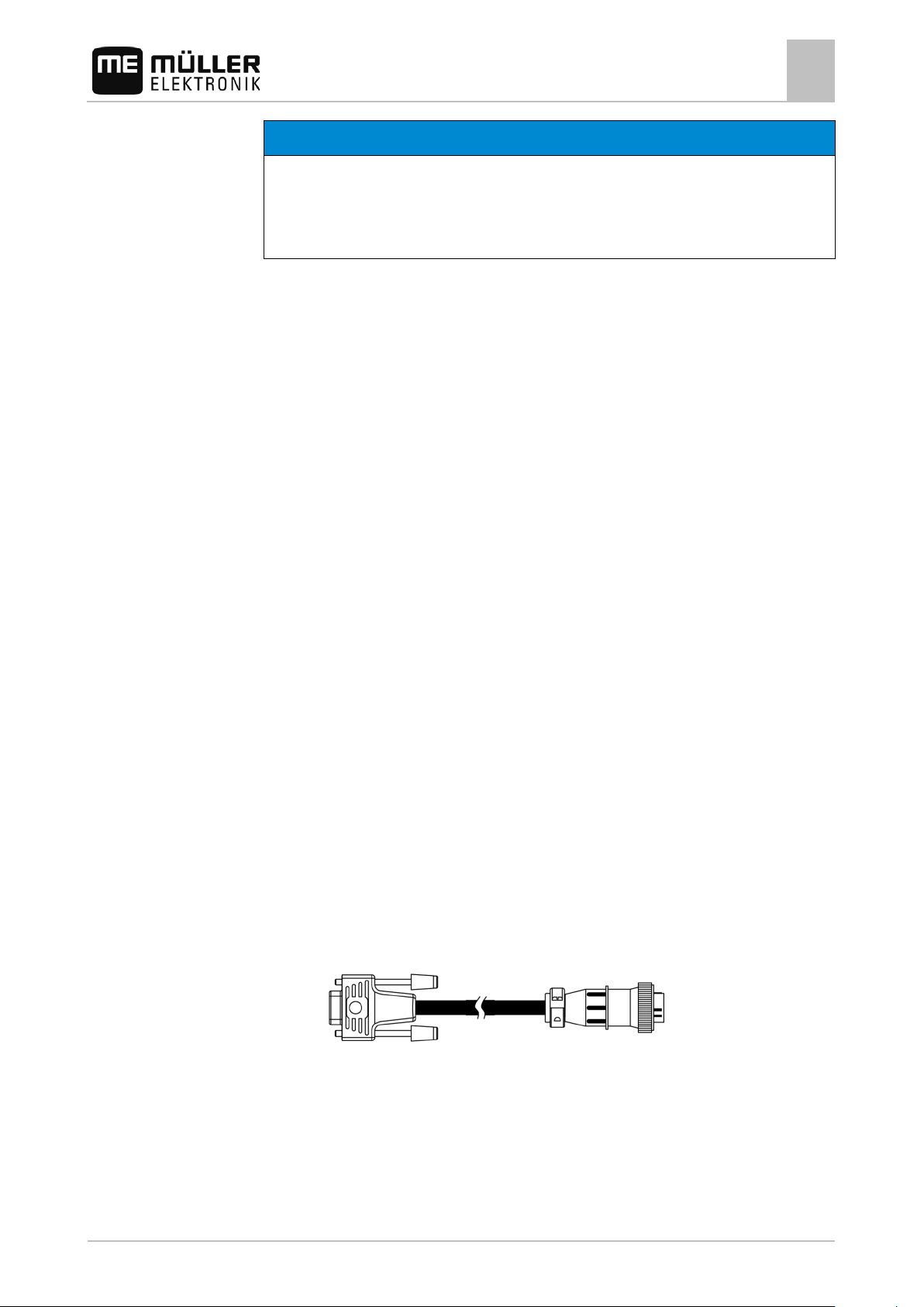
Connecting the terminal to the ISOBUS
If you purchase the ISOBUS-UT app in order to be able to also operate ISOBUS job computers with a
terminal, you must connect this to the ISOBUS.
You will need a different connection cable for this, depending on the model of your tractor.
▪ In tractors which have been subsequently upgraded with an ISOBUS-basic vehicle harness from
Müller-Elektronik, use connector cable A from the ISOBUS-basic vehicle harness.
▪ In tractors which are equipped as standard with ISOBUS and which have an ISOBUS In Cab
Connector, you will need the following connector cable:
– D-Sub <-> CPC connector cable, item no. 30322541
▪ In tractors which are fitted with their own ISOBUS terminal, but in which there is however no
ISOBUS In Cab Connector, you can ask for the ISOBUS In Cab Connector to be retrofitted.
– You can order the appropriate cable from Müller-Elektronik. Our sales team will be glad to
advise you.
– For certain tractors, you can retrofit the connector cable without the ISOBUS In Cab
Connector.
30302710-02-EN V7.20141016 13
Page 14
Procedure
4.4
4.4.1
Procedure
Mounting and installation
4
SIM card
– In certain versions, you will also require the D-Sub <-> CPC connector cable, item no.
30322541
When there is more than one terminal in the tractor cab, you may need to change certain settings in
order to enable two-way communication. Find out more: Using two terminals [➙ 25]
1. Connect the 9-pin plug A of the basic vehicle harness to port A of the terminal.
Which SIM card?
2. Tighten the safety screws on the connector.
SIM card
The terminal must be equipped with a SIM card so that you can use the farmpilot portal. If you do not
intend to use the farmpilot portal, you will not need any SIM card.
You must purchase the SIM card from your mobile phone provider.
Select a mobile phone provider that can guarantee good mobile phone reception on your fields. A
good connection is required in order for work with the farmpilot portal to run smoothly.
The SIM card must meet the following requirements:
▪ It must be GPRS-capable.
▪ It must be PIN-free. Inform your mobile phone provider about this requirement before purchasing
the SIM card.
▪ The contract must enable data transfer.
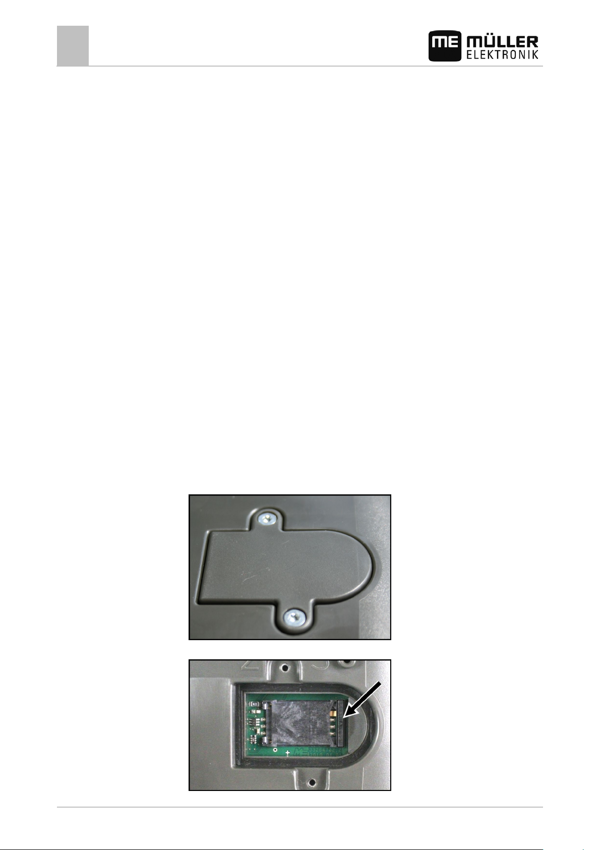
Inserting the SIM card
Required tool
▪ Torx TX10 screwdriver
1. Switch off the terminal and disconnect all cable connections to other equipment.
2. Unscrew the SIM card cover on the reverse of the terminal. Use a Torx TX10 screwdriver.
3. Press latch release with finger nail.
14 30302710-02-EN V7.20141016
Page 15
4.5
Mounting and installation
Connecting the ISO printer to the terminal
4
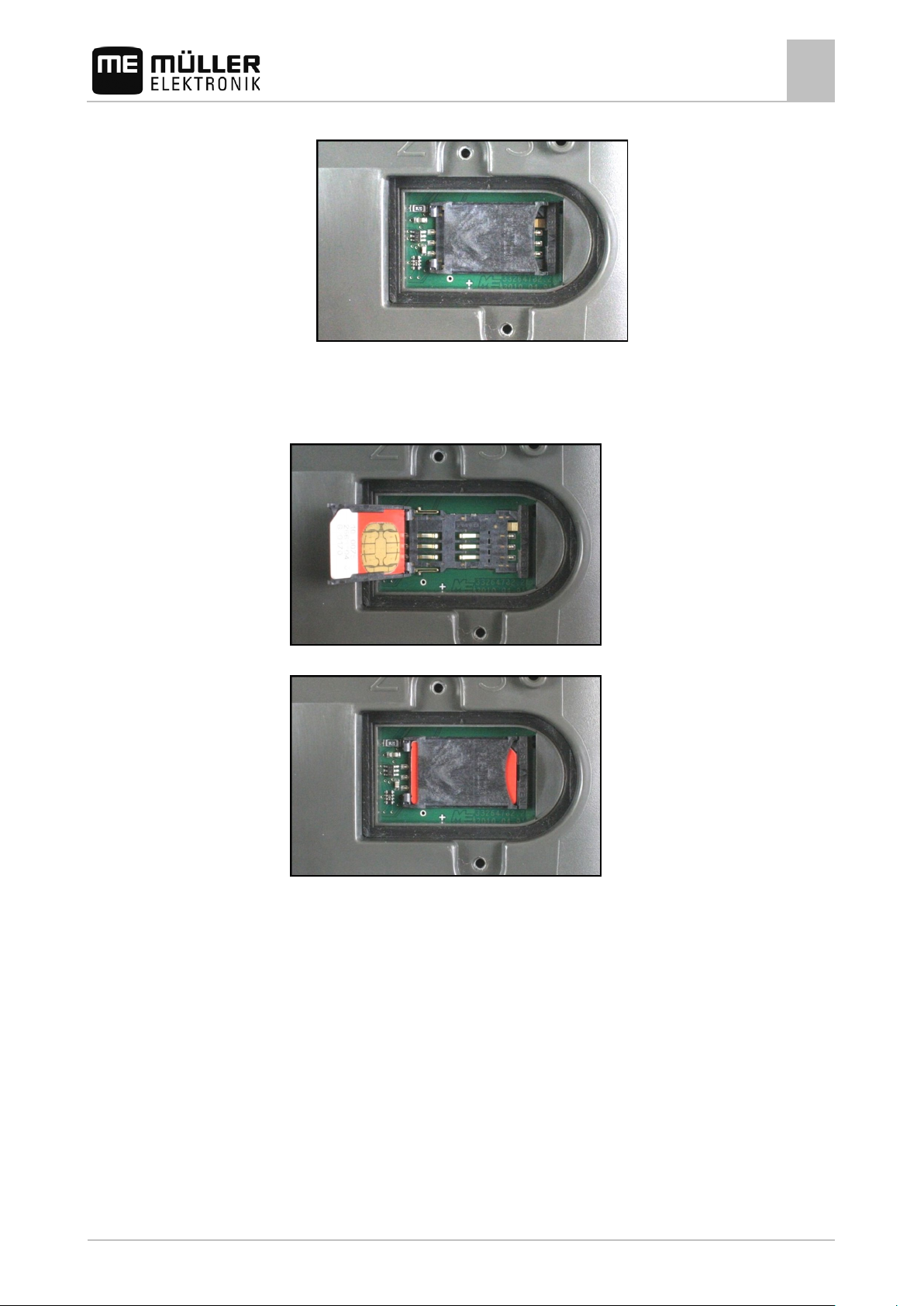
⇨ Card holder will be unlatched:
4. Raise the card holder. The card holder can be raised on the right hand side where the casing is
rounded. The card holder is held in place by hinges on the other side.
5. Slide the SIM card into the card holder. Following installation, the chip on the card must be in
contact with the circuit board. The card must be positioned as shown in the picture.
6. Shut the card holder.
7. Press the card holder lightly onto the circuit board, until it clicks into place on the right hand side.
8. CAUTION! Tighten the screws, but not too tight, otherwise the cover might be damaged.
9. Screw the cover back on. Make sure that the rubber seal is positioned between the cover and
the casing.
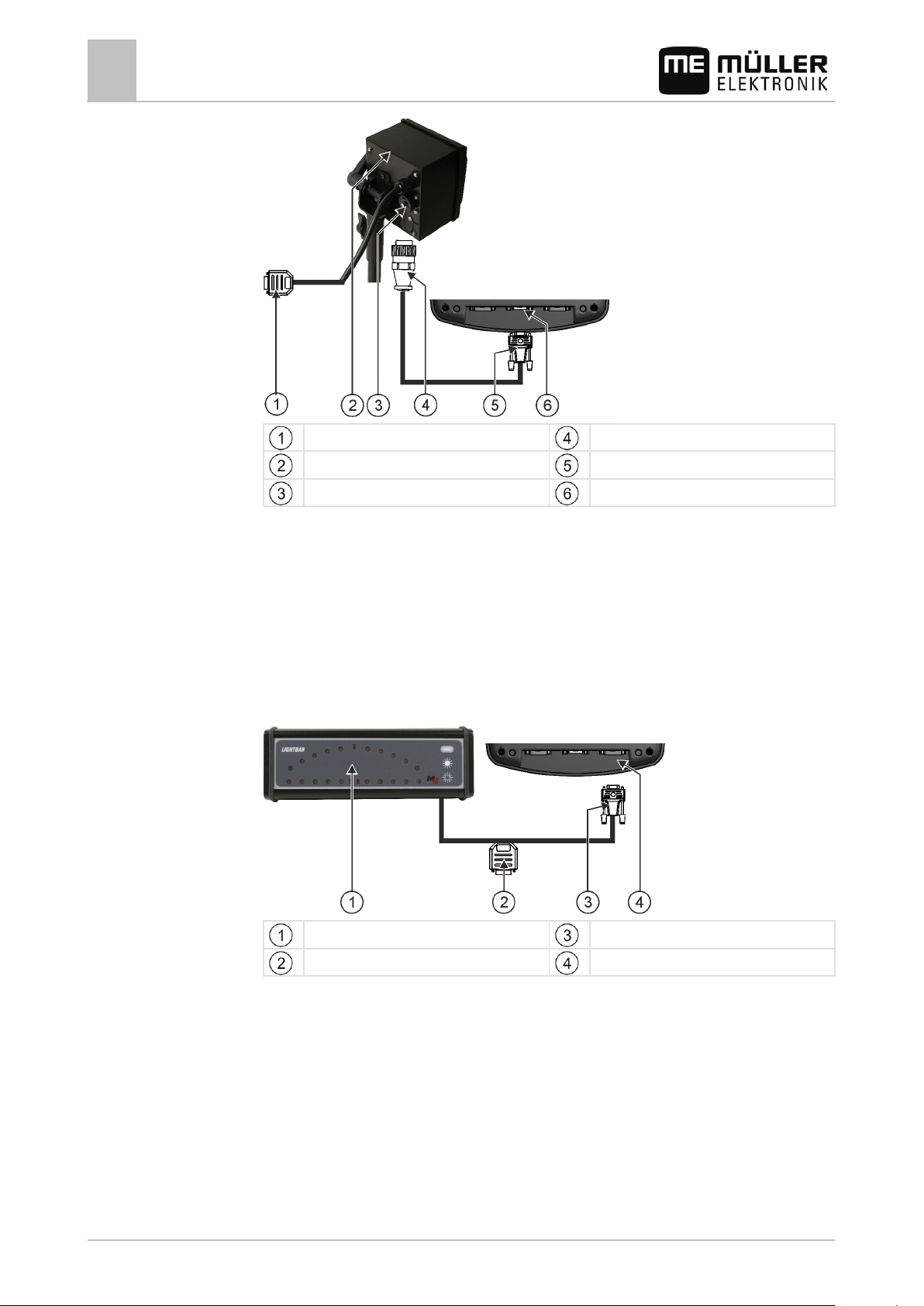
Connecting the ISO printer to the terminal
The ISO printer is used to print out information from an ISO-XML task.
30302710-02-EN V7.20141016 15
Page 16
4.6
4.7
Mounting and installation
4
Connecting the ME LightBar to the terminal
9-pin Sub-D plug for connection to ISOBUS
ISO printer
ISO printer socket
When you connect a GPS receiver to the terminal, you must activate [➙ 55] and configure it.
Plug for connection to ISO printer socket
Connector for connection to the terminal
CAN-Bus connection
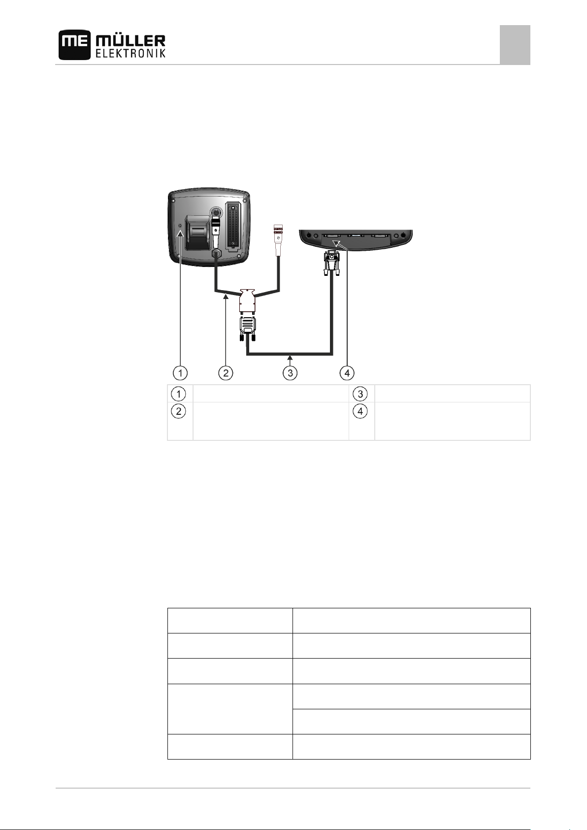
Connecting the ME LightBar to the terminal
The ME LightBar is a parallel guidance display made by Müller-Elektronik, which can be mounted
near the windshield.
The ME LightBar works with position data and guidance lines that are provided by the TRACK-Leader
app. This is why you need the TRACK Leader App to be able to use the ME LightBar.
External LightBar
Plug for connecting a GPS receiver
After connecting an external LightBar to the terminal, you must activate [➙ 39] it.
Connector for connection to the terminal
Serial port RS232
Connecting the on-board computer to the terminal
You can connect a range of on-board computers (non-ISO computers), which communicate using the
LH5000 protocol or the ASD interface, to the terminal.
An appropriate connector cable for each on-board computer which can be connected is available
from Müller-Elektronik. Our sales team will be glad to advise you.
16 30302710-02-EN V7.20141016
Page 17
3032254800
Operating voltage:
Supply voltage of the terminal – 1.5 V
Current consumption
Maximum 200 mA (at 70°C)
5 Hz (GPGGA, GPVTG)
Transmission rate
19200 baud
4.8
Preconditions
Mounting and installation
Connecting the GPS Receiver to the terminal
4
You can find a list of on-board integrated display/controllers that we have tested here:
▪ Transfer target rates via LH5000 [➙ 69]
▪ Switching sections and transferring target rates via ASD [➙ 70]
For other on-board integrated display/controllers and for on-board integrated display/controllers with
other software versions, this function may not work at all or different from how it is described in these
instructions. Because the operating mode and configuration depends on the on-board integrated
display/controller. You must contact the on-board integrated display/controller manufacturer for this.
On-board computer
Adapter cable*
Available as a set with Cable 3, item number:
Null modem cable
Port B on the terminal
*When using an Amatron3 or Amatron+ as on-board integrated display/controller, you will only need a
traditional null modem cable. (Amatron3 and Amatron+ are on-board integrated display/controller
from Amazone)
Connecting the GPS Receiver to the termin al
Each GPS receiver which is connected to the terminal must fulfil the conditions in the table below.
GPS receivers which can be purchased from Müller Elektronik fulfil these conditions.
Technical requirements for using the DGPS Receiver
30302710-02-EN V7.20141016 17
GPS standard NMEA 0183
Refresh rates and signals
1 Hz (GPGSA, GPZDA)
Page 18
Data bits
8
Parity
no
Stop bits
1
CAUTION
devices don't differ from each other.
Procedure
4.9
Mounting and installation
4
Connecting sensors to the terminal
Flow control none
Damage to the equipment caused by short circuit
Pin 4 of port C is live. The voltage depends on the operating voltage of the terminal and is used to
supply the DGPS Receiver from Müller Elektronik.
Other GPS Receivers may suffer damage if connected to this port.
Before connecting a different GPS Receiver:
◦ Check what voltage the terminal is connected to (12 V or 24 V).
◦ Check the pin assignment of the GPS Receiver.
◦ Check the allowable voltage for the GPS Receiver.
◦ Compare the terminal voltage to the allowable voltage for the GPS Receiver.
◦ Compare the pin assignment.
◦ Only connect the GPS Receiver to the terminal, if the voltage range and pin assignment of both
During initial start-up it can take approx. 30 minutes until the GPS Receiver has reception. At
subsequent start-ups it will only take approx. 1-2 minutes.
The GPS receiver is mounted on the roof of the tractor.
You have activated a suitable driver. [➙ 34]
1.
- Switch off the terminal.
2. Guide the connection cable from the GPS receiver into the cab.
3. CAUTION! Ensure that the cable is not laid across sharp edges or at risk of becoming
bent. Lay the cable in a place where nobody can trip over it.
4. Connect the connecting cable of the GPS receiver to port C on the terminal.
Connecting sensors to the terminal
The terminal provides you with the possibility of connecting a sensor or the tractor's 7-pole signal
socket to port B. This allows you for example to use the working position signal in the TRACK-Leader
parallel guide.
Most sensors which can be purchased from Müller Elektronik are fitted with a round 3-pole plug. In
order to connect this to the terminal, you will need an adapter cable. A different adapter cable is
needed for each hardware version of the terminal.
18 30302710-02-EN V7.20141016
Page 19
terminal
pole
From 1.4.1
3-pole plug
Adapter cable, 9-pole socket to 3-pole
31302497
terminal
working position.
pole.
4.10
Mounting and installation
Adapter cable by hardware version
Hardware ver-
Adapter cable Connection Item num-
Connecting the camera to the terminal
sion of the
4
ber
From 3.0.0 3-pole plug Adapter cable, 9-pole bushing to 3-
31302499
You can also connect the terminal to the signal socket.
Cable to the signal socket
Hardware ver-
Connections Connection Item num-
sion of the
From 3.0.0 7-pole to 9-pole socket Cable direct to the signal socket
ber
30322548
Transfers the speed, PTO revolution,
All 3-pole (from the adapter
cable, dependent on the
Cable to the signal socket
Only transfers the working position.
313008
hardware version) to 7-
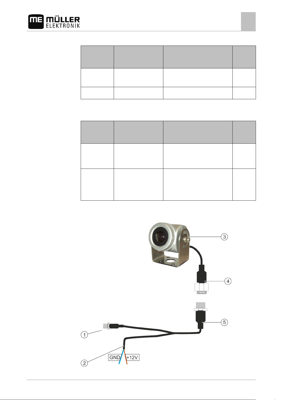
Connecting the camera to the terminal
30302710-02-EN V7.20141016 19
Camera with cable harness
Page 20

+12V (brown) - 12V voltage
Procedure
Mounting and installation
4
Connecting the camera to the terminal
Connection to the terminal
Camera
Cable for connection to the voltage supply.
GND (blue) - Earth
Camera plug
Socket for connection to the camera plug
1. Screw the camera together with its bracket, as described in the assembly instructions of the
camera manufacturer.
2. Connect the camera to the cable harness.
3. CAUTION! When laying out the cable harness, you should ensure that no kinks form in
the cable, and that no one can trip over the laid-out cable.
4. Connect the junction of the cable harness to a power source (12V). Müller-Elektronik offers
different plugs for this purpose, which you can connect to the cable.
5. Connect the cable harness to the camera connection of the terminal.
6. Secure the camera.
7. Activate the camera. [➙ 39]
20 30302710-02-EN V7.20141016
Page 21
▪ Change a parameter value.
▪ Confirm input.
5
5.1
Basic control principles
Basic control principles
Getting to grips with the controls
5
Getting to grips with the controls
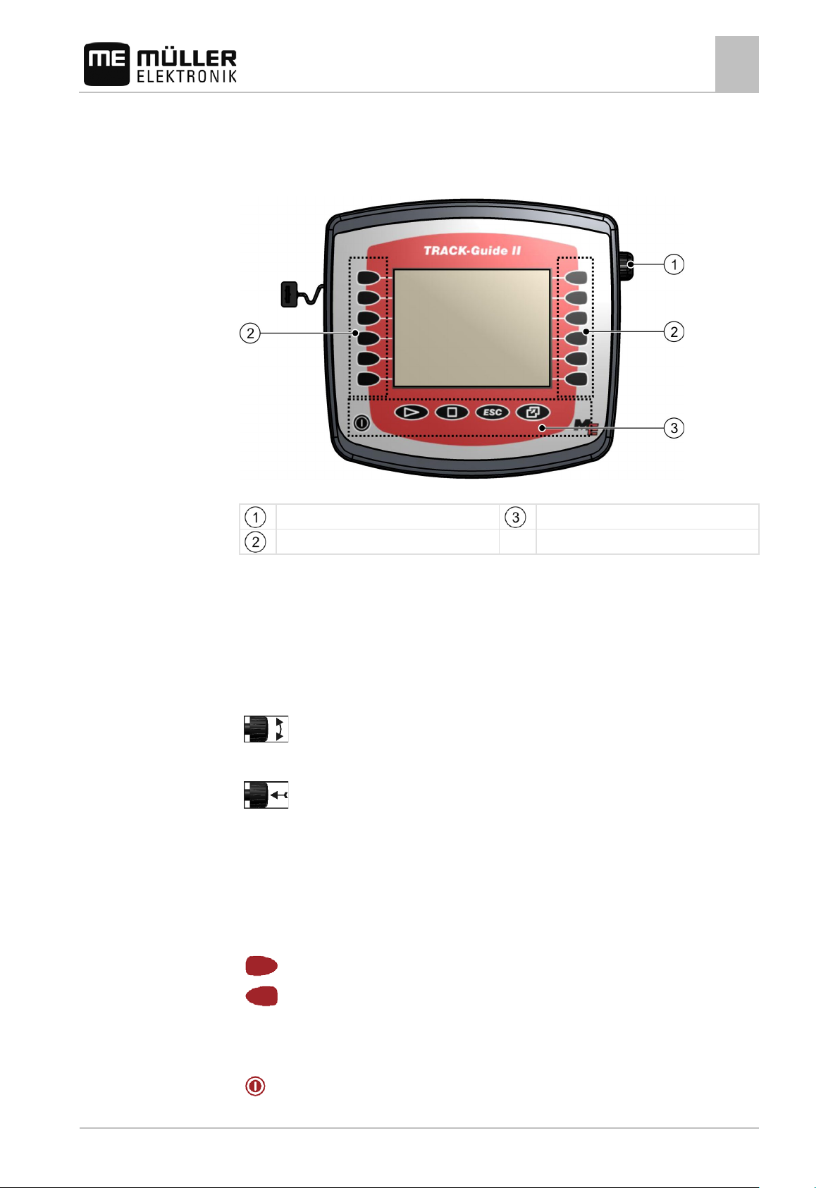
Controls
Terminal controls
Rotary knob
Keys
Function keys
Rotary knob
The rotary knob is located in the top right hand corner of the terminal.
Control with the rotary knob may vary slightly between the different applications.
You can use the rotary knob to perform the following actions:
Turning the rotary knob:
▪ Move the cursor up and down.
Pressing the rotary knob:
▪ Click on the selected line.
▪ Activate parameter.
30302710-02-EN V7.20141016 21
Function keys
Operating the function keys is the same across all applications.
Performing the functions depicted on the display
Keys
Switch the terminal on and off
Page 22
Hide warning messages and alerts
Exit the "Selection menu" application
5.2
Procedure
Basic control principles
5
Initial start-up
Has no function
Has no function
Exit screen
Cancel input
Initial start-up
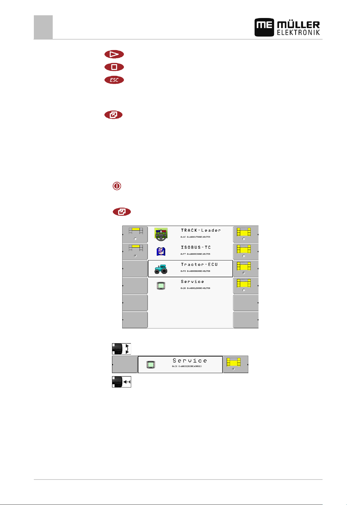
Open the "Selection menu" application
This is how you start the terminal for the first time:
You have mounted and connected the terminal.
1.
- Switch on the terminal.
2. Wait for approx. 15 seconds until all applications have been loaded.
3.
- Open the "Selection menu" application.
⇨ The following screen will appear:
4. In the selection menu you can select which application you wish to display next.
5.
- Select the "Service" line. The "Service" line must be framed by a black square:
6.
22 30302710-02-EN V7.20141016
- Click on the "Service" line.
Page 23
5.3
5.4
Basic control principles
Configuration sequence
5
⇨ The following screen will appear:
⇨ You have opened the "Service" application.
7. Configuring the terminal in the Service application [➙ 30]
Configuration sequence
Depending on the terminal that you have and which apps are activated, you will need to configure the
terminal and its accessories in different points.
You must make these settings during the initial commissioning:
▪ Activate the driver of the GPS receiver. [➙ 34]
▪ Configure the GPS receiver. [➙ 35]
▪ Input the position of the GPS receiver (only when also using SECTION-Control). [➙ 63]
Once you have made these settings, the terminal is ready to operate.
Note however that you will need to configure the TRACK-Leader and FIELD-Nav applications in
detail. To do this, read the instructions for these applications.
The number of settings is dependent on the number of functions that you are using, and which
machines are operated with the terminal.
Using the function keys
Whenever you use the function keys, you will activate the function depicted on the adjacent function
icon.
30302710-02-EN V7.20141016 23
Page 24
CAUTION
◦ Only press the function key when you are sure that no danger is posed to people or property.
icon.
5.5
Procedure
Basic control principles
5
Restarting the terminal
Danger of pressing the function keys without care
When pressing function keys, components of the connected machine can be moved or activated.
As a result, people can be injured and property damaged.
Before pressing a function key:
◦ Make sure you know what will happen when you press the function key.
◦ Consult the Operating Instructions of the connected machine or of the agricultural equipment to
establish what dangers could arise from pressing that key.
◦ Fulfill all the measures described in the machine's Operating Instructions in order to avoid
danger.
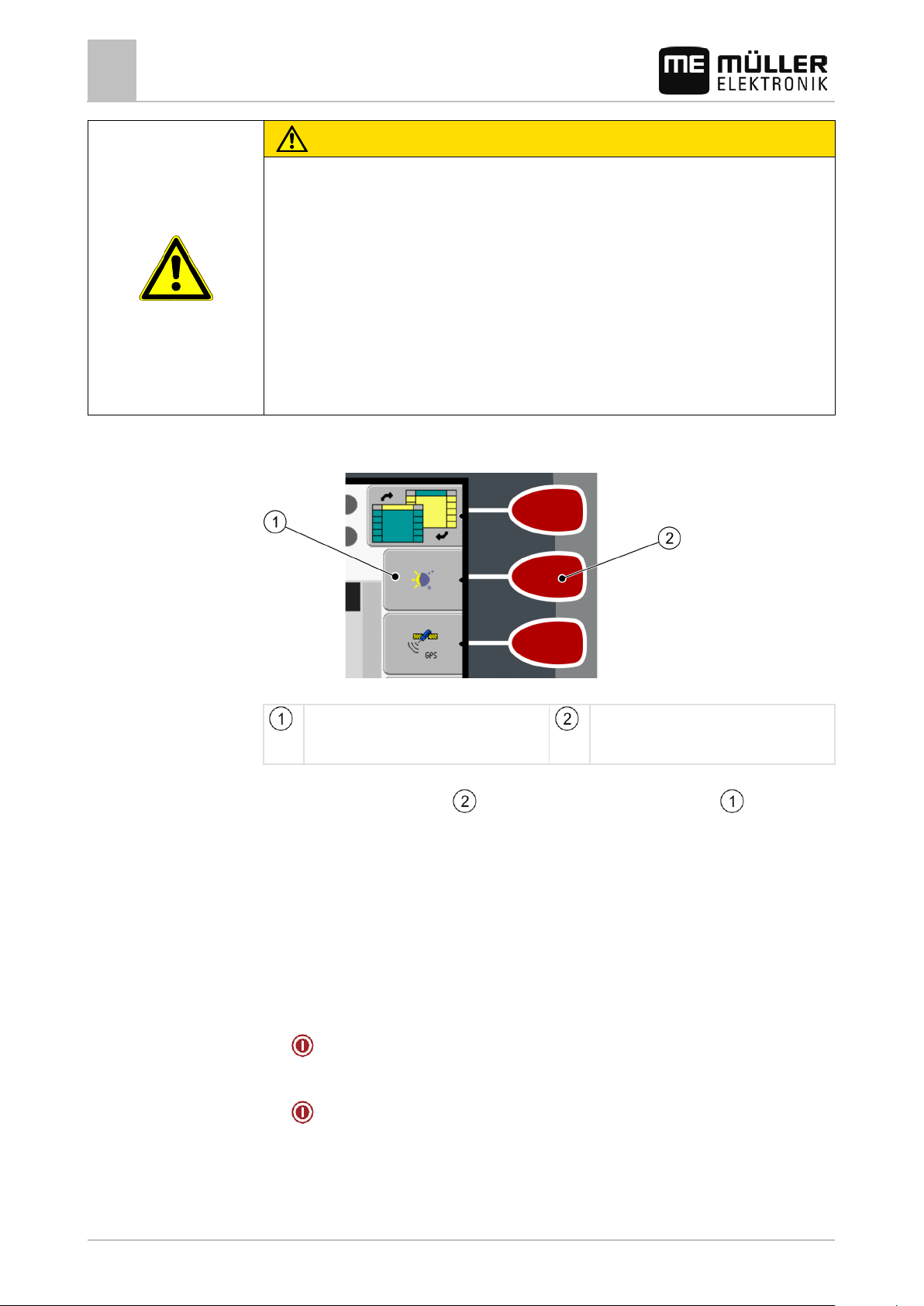
When you press a function key, the function / operation depicted on the function icon will be
performed.
Example
Using the function keys
Function icon
Depiction of an available function.
Function key
Performs the function depicted on the function
When you press the function key , the function depicted on the function icon will be
activated.
If not function icon appears next to a function key, this means that this function key has no function at
present.
Restarting the terminal
When restarting the terminal, you must give the connected jobcomputers enough time to restart as
well. For this reason, always wait approx. 30 seconds after switching off the terminal before switching
the terminal back on.
1. - Switch off the terminal.
2. Wait 30 seconds until the jobcomputers have also been switched off.
3.
- Switch on the terminal.
24 30302710-02-EN V7.20141016
Page 25

5.6
Controls
Procedure
5.7
Basic control principles
Inputting data
5
Inputting data
All data must be entered on the data input screen.
Data input screen
Below the characters, you will find 5 icons which will assist you when entering the data.
Delete characters
Move cursor to the left
Move cursor to the right
Confirm and finish input.
No function
This is how you enter the data:
The data input screen has been opened:
1.
2.
- Select the desired character.
- Click on the selected character.
3. When all characters have been entered, select the "OK" symbol with the rotary button and click.
⇨ The input will be applied.
Using two terminals
When installing the terminal in a tractor in which there is already another terminal, you must configure
both terminals so that communication works between both units.
The following table will tell you which settings you need to configure, and the chapters in which these
are described.
30302710-02-EN V7.20141016 25
Page 26

Parameter
Chapter
TC?
Basic control principles
5
Using two terminals
Run as auxiliary terminal
Login as ISOBUS-UT
Connection with ISOBUS-
List of connections
Setting the purpose of the terminal [➙ 46]
Setting the purpose of the terminal [➙ 46]
Configuring the parameters for a vehicle profile [➙ 57]
Configuring the list of connections [➙ 67]
26 30302710-02-EN V7.20141016
Page 27

ISO name of the application
displayed in the header.
main display.
header
knob.
6
Controls
6.1
6.2
Opening applications in the selection menu
Display layout in the selection menu
6
Opening applications in the selection menu
In the selection menu you can choose which application you wish to view on the display.
You can open the selection menu at any time. This will not close the application currently running.
Open the selection menu
Press again – open the most recently activated application
Display the application in the header of the split display.
Display the application in the main section of the display.
Display layout in the selection menu
The display is split into the following sections:
▪ Function icons – left and right
▪ Applications section – in the middle, between the function icons.
Sections in the selection menu
Name of an application
Function icons on the left
Select an application which will later be
Selection
The selected application is displayed in the
ISO ID of the application
Selection
The selected application is displayed on the
Function icons on the right
Open an application on the main display.
Cursor
Open the selected application using the rotary
Opening applications
You can perform the following actions in the selection menu:
▪ Open an application.
▪ Display an application in the header of the split display.
30302710-02-EN V7.20141016 27
Page 28

that is currently running.
Function icon
Function
Procedure
6.3
Opening applications in the selection menu
6
Segmentation of the display
1. - Set which application is to be displayed in the header of the split display.
⇨ The function icon of the selected application is marked with a dot on the left hand side:
2. Start the application for the main display. There are several ways to do so:
a) With the rotary knob:
- Select the desired application
- Open the selected application
b) Using the function keys on the right hand side:
- Display the application shown next to the function icon.
⇨ Both applications will appear on the display.
Segmentation of the display
The display of the terminal is split into two sections.
A different application is displayed in each section. This allows you, for example, to control the tractor
on the field and monitor the field sprayer at the same time. This means that you will not need an
additional terminal.
Segmentation of the display
Header – informative section.
The header allows you to display information
from an application.
Main screen – section used for control.
The main display shows the application
currently running, function icons and the
information you need to control the application
28 30302710-02-EN V7.20141016
In the selection menu you can see which applications can be run with the split display.
Switch applications in the header section.
Page 29

Function icon
Function
Opening applications in the selection menu
Segmentation of the display
6
Swap applications between the header section and the main section of the
display.
30302710-02-EN V7.20141016 29
Page 30

rotary knob.
installed software
Function icon
Meaning
Only appears if…
7
7.1
Controls
Configuring the terminal in the Service application
7
Controls in the Service application
Configuring the terminal in the Service application
In the "Service" application you can configure the terminal and activate the connected farm
equipment.
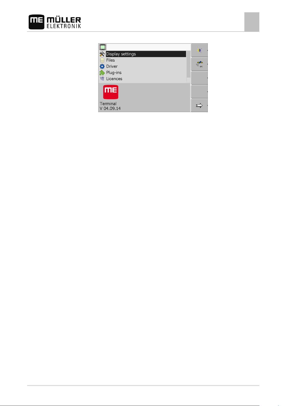
Once you have launched the "Service" application, you will be shown the following screen:
Start screen of the "Service" application
Main section
Screen contents
Cursor
Selects a line that can be clicked on with the
Version number
Name of the terminal and version of the
Function icons section
Icons that can be pressed on this screen.
Controls in the Ser v ic e appl ic a t i on
The Service application is controlled using the rotary knob and the function buttons.
Some of the function icons explained here will only appear if a specific function is activated. This
limits the information shown on the terminal to just the information that you need for your work.
Scroll There is one more page with
function icons.
Return
Activate day mode
Activate night mode
File cannot be deleted (grey) Selected object cannot be
deleted
30 30302710-02-EN V7.20141016
Page 31

Function icon
Meaning
Only appears if…
7.2
Icons
7.3
Procedure
Configuring the terminal in the Service application
Icons in the Service application
7
Delete file (red) Selected object can be deleted
Configure GPS receiver GPS receiver is activated
Configuring farmpilot farmpilot portal is activated
Open the Diagnostics screen Diagnostics is activated
Retrieve default values.
Display DGPS connection status
Associating the buttons on a joystick with
Driver "Auxiliary2" is activated
functions
Icons in the Service application
You will find the following icons in the Service application.
Function is activated
Function is deactivated
Changing the lang ua g e
When you switch on the terminal for the first time, the text may appear in a foreign language (in
German).
If you change the language in the Service application, you also change the language for all
applications and the ISOBUS job computer.
If a connected ISOBUS job computer cannot activate the selected language, a standard language will
be activated.
1. - Switch on the terminal.
2.
30302710-02-EN V7.20141016 31
- Press.
Page 32

7.4
Configuring the terminal in the Service application
7
Basic settings
⇨ The following screen will appear:
3.
- Click on "Service".
⇨ The following screen will appear:
The texts on this screen may appear in a foreign language.
4.
5.
6.
7.
- Click on "Terminal-Einstellungen“ ("Display settings").
- Click on "Sprache" ("Language").
- Select the abbreviation of your language.
- Press.
⇨ The following message will appear: “Restart the terminal.“
8.
- Press.
⇨ The language in the "Service" application will be changed. Language will be changed in
other application only after a terminal restart.
9.
⇨ The language in other applications will be changed.
- Restart terminal.
Basic settings
The basic settings include: Language, Time, Measurement units.
All settings which you make here will also apply to other applications and in connected ISOBUS job
computers.
32 30302710-02-EN V7.20141016
Page 33

Parameter
Sub-parameter
Meaning
Day
Adjusting brightness for day mode
Night
Adjusting brightness for night mode
1 = night mode is activated
Volume
Adjust volume
Date
Setting current date
Time
Setting current time
-1 = GMT -1 hour
Language
Selecting language
Metric
Displays all units in metrical s y s tem
US
Displays all units in US system
Procedure
List of parameters
7.5
Configuring the terminal in the Service application
GPS receiver
7
1. Switch to the "Display settings" screen:
| Service | Display settings
⇨ The following screen will appear:
2.
- Change the desired parameter.
Brightness
Night mode Switching night mode on and off
0 = day mode is activated
Date / time
Time zone 0 = Time zone: Greenwich Mean Time (GMT)
1 = GMT +1 hour (Germany)
30302710-02-EN V7.20141016 33
Measurement units
Imperial Displays all units in imperial system
Keyboard brightness Setting the level of keyboard brightness in percent
GPS receiver
When you connect a GPS receiver to the terminal, you must activate and configure it.
Page 34

Driver name
GPS receiver
application.
cannot thus be configured.
CAUTION
driver.
7.5.1
Procedure
Configuring the terminal in the Service application
7
GPS receiver
Activating the GPS receiver
In order to enable the GPS receiver, you must first select the driver for the connected receiver.
A driver is a small program that controls connected device. The drivers for the devices supplied by
Müller-Elektronik are pre-installed on the terminal.
Available drivers
deactivated No GPS receiver is connected.
PSR CAN Select this driver if the GPS receiver is connected to the job
computer PSR. The signals are transferred via the CAN cable to
the terminal. The receiver will be directly configured in the PSR
A100, A101 Driver for the Müller-Elektronik A100 and A101 GPS receivers. For
receivers which are connected to the serial interface.
Standard Driver for unknown GPS receivers. For receivers which are
connected to the serial interface.
This driver is activated by default. The connected GPS receiver
AG-STAR, SMART-6L Driver for the Müller-Elektronik AG-STAR and SMART-6L GPS
receivers. For receivers which are connected to the serial interface.
Incorrect driver
Damage to the GPS receiver.
◦ Before connecting a GPS receiver to the terminal, you must always activate the appropriate
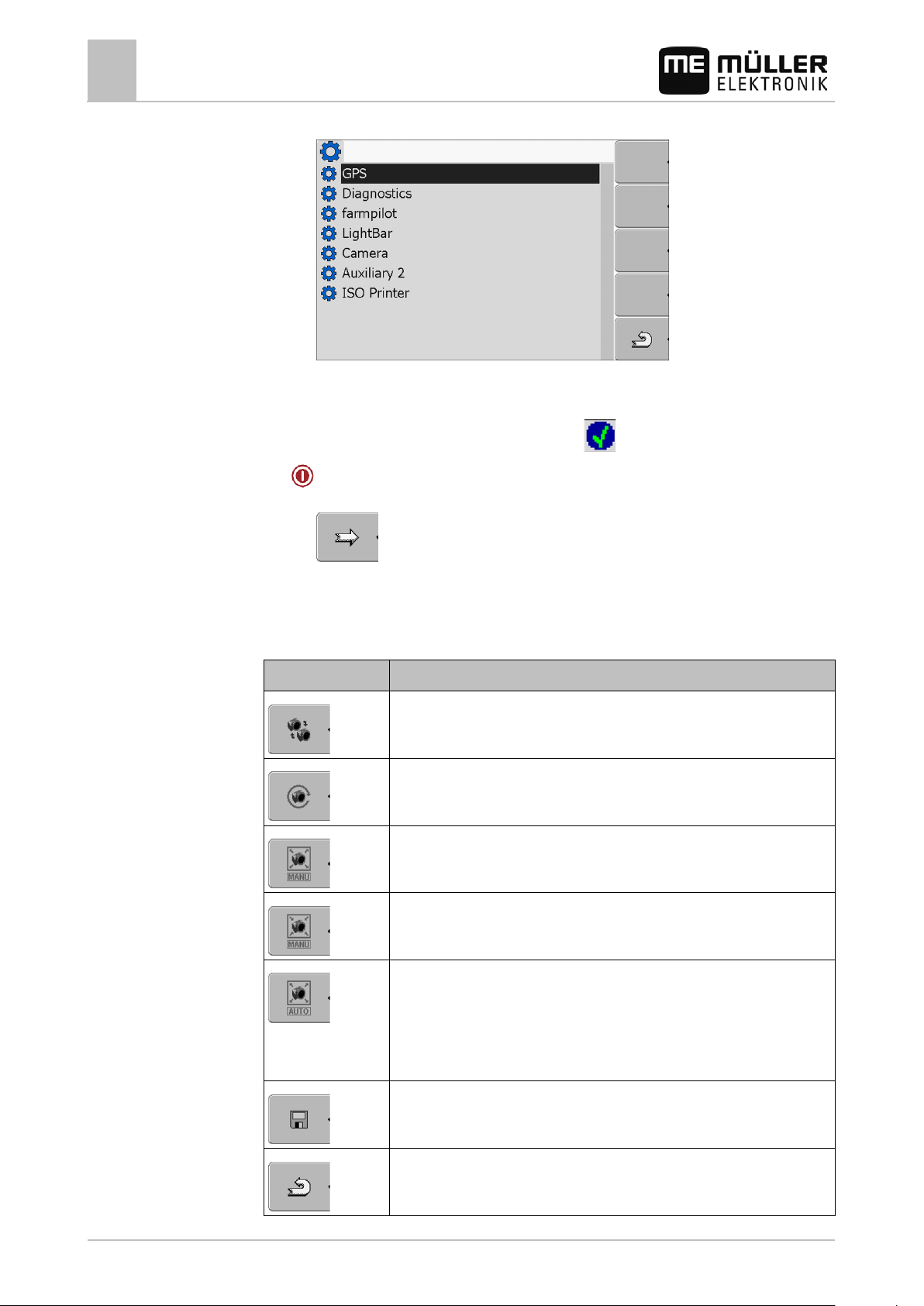
1. Switch to the "Driver" screen:
| Service | Driver
⇨ The following screen will appear:
2. Select "GPS".
34 30302710-02-EN V7.20141016
Page 35

Function icon
Function
7.5.2
Procedure
Configuring the terminal in the Service application
GPS receiver
7
3. Click on "GPS".
⇨ The installed drivers will appear.
⇨ The
icon will appear next to the active driver.
4. Mark the line with the correct driver.
5. Click on the selected line.
⇨ The following icon will appear next to the driver
6.
- Restart the terminal.
⇨ GPS receiver is activated.
⇨ The following function icon will appear in the start screen of the "Service" application:
⇨ You have activated the GPS receiver.
Configuring the GPS receiver
The internal software for each GPS receiver must be configured. You can configure the following
GPS receivers offered by Müller-Elektronik via the terminal:
▪ A100, A101
▪ AG-STAR, SMART-6L
All other GPS receivers must be configured in accordance with their manufacturer's instructions.
Reset the configuration of the DGPS receiver to default values
Display DGPS connection status
To configure the parameters:
A GPS receiver is connected to socket C of the terminal.
The GPS receiver is connected directly to the terminal. Additional devices such as ME LightBar
or tilt module may not be connected in between.
The appropriate driver is activated.
30302710-02-EN V7.20141016 35
Page 36

Configuring the terminal in the Service application
7
GPS receiver
The driver of the ME Lightbar "LightBar" is deactivated. Otherwise the DGPS receiver cannot be
configured.
1. Switch to the "GPS" screen:
| Service |
⇨ The following screen appears:
2.
- Click on the desired parameter. First of all, set the "Correction signal" parameter.
⇨ A selection list will appear.
3.
⇨ The
4.
- Select the desired value.
icon will appear next to the value.
- Back
⇨ For some parameters is it necessary to restart the terminal. In these cases, the following
notification will appear:
"Restart the terminal."
⇨ You have configured the DGPS receiver.
5. Reconnect all of the additional devices that you had disconnected for the configuration.
Parameters for the GPS receiver
Baud rate
Only appears when the "Standard" driver is selected.
Setting for the speed at which the GPS receiver sends data to the terminal. The parameter sets the
baud rate for the terminal.
Satellite 1 and Satellite 2
Satellite 1 – primary DGPS satellite. The DGPS receiver will connect to this satellite in the first
instance.
Satellite 2 – secondary DGPS satellite. The DGPS receiver will only connect to this satellite in the
event that the primary satellite fails.
Your satellite selection will depend on which satellite currently has the best availability in your region.
Potential values:
▪ "Auto"
The software automatically selects the current best satellite. This setting is not recommended, as
it slows down the start-up of the DGPS receiver.
36 30302710-02-EN V7.20141016
Page 37

Configuring the terminal in the Service application
GPS receiver
7
▪ Name of the satellite. Which satellites are shown here is dependent on the driver and correction
signal that you have activated.
Steering
This parameter activates the "Automatic steering" assistance function in the GPS receiver.
If you want to connect your existing GPS receiver to a steering job computer, you have to configure
the "Steering" parameter.
Potential values:
▪ "On"
Activates automatic steering assistance.
▪ "Off"
Deactivates automatic steering assistance.
Correction signal
Type of correction signal for the DGPS receiver.
The correction signals which are available is dependent on the activated driver.
Potential values:
▪ For the "A100, A101" driver:
– "WAAS/EGNOS"
Correction signal for Europe, North America, Russia and Japan.
– "E-DIF"
Internal calculation of correction data.
Only functions with a special version of the A100 DGPS receiver, item no. 30302464. This
receiver is no longer sold by Müller-Elektronik.
▪ For the "AG-STAR, SMART-6L" driver
When a AG-STAR DGPS/Glonass receiver is connected:
– "EGNOS-EU"
– "WAAS-US"
– "MSAS-JP"
– "EGNOS-EU + GL1DE"
– "WAAS-US + GL1DE"
– "MSAS-JP + GL1DE"
– "GPS/Glonass GL1DE 1"
– "GPS/Glonass GL1DE 2"
When a SMART-6L DGPS/Glonass receiver is connected:
– EGNOS/WAAS
– EGNOS/WAAS + GL1DE
– GL1DE
– RTK radio (RTK license required [➙ 38])
– RTK GSM (RTK license required [➙ 38])
Correction signal format
30302710-02-EN V7.20141016 37
Page 38

7.6
Procedure
Configuring the terminal in the Service application
7
Configuring the "GPS TILT-Module" terrain compensation
Format of correction signal for the SMART-6L DGPS/Glonass receiver.
Only appears when "RTK radio" or "RTK GSM" correction signals have been selected.
Potential values:
▪ RTCM V3
▪ CMR/CMR+
▪ RTCA
For the correction signal format which you must select, please refer to your correction service.
Terrain compensation
The GPS TILT-Module terrain compensation is configured using this parameter.
You can order the terrain compensation from Müller-Elektronik with the following item number:
30302495.
RTK license for SMART-6L
You will need a SMART-6L DGPS/Glonass receiver and RTK license in order to work with RTK
correction signals.
The RTK license is inserted by Müller-Elektronik. You will need to either order a license at the same
time as you order the receiver, or send in your receiver.
Configuring the "G PS TILT-Module" terrain compensation
The "GPS TILT-Module" terrain compensation is connected.
The tractor is positioned on level ground.
The driver of the external ME LightBar is deactivated.
1. If any additional devices (e.g. ME LightBar) are connected to the cable between the terminal and
the tilt module, disconnect them. The tilt module must be connected directly to the terminal. After
the tilt module has been configured, these additional devices must be reconnected.
2. Measure the distance between the GPS receiver and the ground surface.
3. Switch on the terminal.
4. Switch to the tilt module configuration screen:
| Service | | Tilt module
⇨ The following screen appears:
5. Enter the distance between the GPS receiver and the ground surface in the line "GPS receiver
height".
38 30302710-02-EN V7.20141016
Page 39

7.7
7.8
7.8.1
Procedure
Configuring the terminal in the Service application
Activating an external LightBar
7
6. Position the tractor on a ground surface that is known to be level.
7. Click on the line "Null point calibration".
⇨ The position of the tilt module on level ground is being calibrated.
⇨ After calibration, the angle 0 will appear on the "Angle" line. The displayed angle will change
with any tilt of the tractor.
Procedure
8. Reconnect all of the additional devices that you had disconnected for the configuration.
Activating an external LightB ar
If you connected an external LightBar to the terminal, you must activate it.
To activate the external LightBar, you must first activate its driver.
You can order the external LightBar from Müller-Elektronik with the following item number: 30302490.
1. Switch to screen "Driver":
| Service | Driver
⇨ The following screen will appear:
2. Click on "LightBar".
⇨ The installed drivers will appear.
3. Click on the "Lightbar" driver.
⇨ Next to the driver the icon
4.
⇨ You have activated the external LightBar.
Camera
- Restart terminal.
will appear.
Activating a camera
In order to activate a camera, you must activate its driver.
1. Switch to the "Driver" screen:
| Service | Driver
30302710-02-EN V7.20141016 39
Page 40
Function icon
Meaning
This only works if the vehicle is equipped with a suitable sensor.
7.8.2
Controls
Configuring the terminal in the Service application
7
Camera
⇨ The following screen will appear:
2. Click on "Camera".
3. Click on the "Camera" driver.
⇨ The following icon will appear next to the driver
4.
- Restart the terminal.
⇨ The following function icon will appear in the start screen of the "Service" application:
5. You have activated the camera driver.
Operating the camera
Switching between several cameras.
Rotating image.
Zooming in for camera images.
40 30302710-02-EN V7.20141016
Zooming out for camera images.
Activating automatic camera mode.
In automatic mode the camera images will be automatically displayed if a
sensor sends a signal to do so.
Saving camera settings.
Exiting camera.
Page 41

7.9
Configuring the terminal in the Service application
Configuring the joystick button allocations
7
Procedure
You can press the function keys even if the camera is set to full screen mode.
You have connected and activated the camera.
1. Switch to the "Camera" screen:
| Service | |
⇨ The following screen will appear
2. Use the function keys to control the camera.
Configuring the joy s t i c k butt on allocations
The terminal offers you the possibility of assigning the functions of an ISOBUS job computer to the
buttons of the joystick. To do so, the ISOBUS job computer and the joystick must fulfil the Auxiliary 2
specification requirements from the ISOBUS standard.
Selecting the function
Area with available functions
Icon for the ISOBUS job computer
Icon for the function
Cursor
Button assignment area
Button assignment. The example of the Müller Elektronik multi-function grip (MFG)
30302710-02-EN V7.20141016 41
Page 42

multi-function grip)
Function icon
Meaning
Procedure
Procedure
Configuring the terminal in the Service application
7
Configuring the joystick button allocations
LED colour (position of the side-switch on the
Multi-function grip version
Button to which a function is assigned
Multi-function grip software version
Other buttons
Version information
Deletes all assignments
Deletes the marked assignment
Confirms all assignments
To activate the driver for this function:
1. Switch to the "Driver" screen:
| Service | Driver
2. Activate the value "Auxiliary2" in driver "Auxiliary 2".
3.
- Restart the terminal.
To configure the button assignment:
The joystick and ISOBUS job computer are connected and support the "Auxiliary 2" protocol.
You have activated the driver "Auxiliary2"
1. To switch to the joystick's configuration mask:
| Service | |
⇨ The following screen will appear:
⇨ The icons which appear here will be dependent on the software of the connected ISOBUS
job computer. This is only an example.
2.
42 30302710-02-EN V7.20141016
- Select the function which you wish to assign to a button.
Page 43

7.10
Procedure
Configuring the terminal in the Service application
Adjusting the brightness for day or night mode
7
⇨ The following screen will appear:
⇨ The content of the screen will depend on the software of the connected joystick.
3. Select the button to which you want to assign the selected function. This is only an example.
4.
5.
- Exit the screen.
- Restart the terminal.
⇨ After restarting, a screen with an overview of the assignments appears.
⇨ If this screen does not appear, open the Service application.
6. Confirm the notification "Scroll to the end."
7. Scroll with the knob all the way to the bottom of the list.
⇨ The following icon will appear in green on the right-hand side:
8.
⇨ You have completed the assignments and can now operate the machine with the joystick.
- Confirm the assignments. You must re-confirm the assignments after each restart.
Adjusting the brig htness for day or night mode
In this chapter you will learn how to adjust the brightness of the display for day or night mode.
1. Open the "Service" application:
| Service
⇨ The following screen will appear:
2. Change the operating mode.
Depending on which operating mode is currently active, you can use one of the function icons:
30302710-02-EN V7.20141016 43
Page 44

Name of the plug-in
Includes the following applications
File Server
File Server
Tractor-ECU
Tractor-ECU
VARIABLE RATE-Control
FIELD-Nav
FIELD-Nav
7.11
Procedure
Configuring the terminal in the Service application
7
Enabling and disabling applications
– Activate day mode.
– Activate night mode.
⇨ The brightness of the display will be adjusted immediately.
Enabling and disabling applications
In the "Service" application you can activate and deactivate other applications that are installed on
the terminal.
The applications are installed in packages, in so-called plug ins. A plug-in can contain several
applications.
You can for example deactivate a plugin if you do not want to use it. The plug-in will then not be
displayed in the selection menu.
Serial Interface Serial interface for the transfer of data to the on-
board computer.
ISOBUS-TC ISOBUS-TC
TRACK-Leader TRACK-Leader
SECTION-Control
TRACK-Leader TOP
To activate and deactivate plug-ins:
1. Switch to the "Plug-ins" screen:
| Service | Plug-ins
⇨ The following screen will appear:
44 30302710-02-EN V7.20141016
Page 45

7.12
Procedure
Configuring the terminal in the Service application
Activating licenses for full versions of the software
7
2. - Click on the desired plugin.
⇨ The icon preceding the name of the plugin indicates whether the plugin is activated or
deactivated.
3.
- Exit screen.
⇨ The following notification will appear:
“Restart the terminal.“
4.
5.
⇨ All activated plugins will appear in the selection menu.
- Confirm.
- Restart terminal.
Activating licenses for full versions of the software
Several applications are pre-installed on the terminal, which you can use for trial purposes for up to
50 hours. [➙ 9] After this time has elapsed, they will be automatically deactivated. The amount of
free usage time remaining is shown in brackets next to the name of the application.
To activate a license you will require an activation number, which you will receive on purchasing an
application from Müller-Elektronik. If you request the activation number by phone or by email, you will
be required to give our staff the following information:
▪ Code – Found under the name of the application on the "License management" screen.
▪ Serial number of the terminal – Found on the nameplate on the reverse of the terminal.
▪ Item number of the terminal – Found on the nameplate on the reverse of the terminal.
The activation number is entered as follows:
1. Switch to the "Licenses" screen:
| Service | Licenses
⇨ The following screen will appear:
2. Click on the desired application.
30302710-02-EN V7.20141016 45
Page 46

NOTICE
◦ Think very carefully about which file you wish to delete.
7.13
7.14
Configuring the terminal in the Service application
7
Setting the purpose of the terminal
⇨ The following screen will appear:
3. Enter the activation number in the "Key" field. You will receive the activation number on
purchasing a software license.
4. Confirm
Procedure
⇨ The following icon will appear next to the application on the "Licenses" screen:
⇨ The application is activated. You can use the application without any restrictions.
Setting the purpose of the terminal
If you use more than one terminal, you can decide how you want to use this terminal.
The following options are available to you:
▪ "Login as ISOBUS-UT"
Activate this parameter if you want the ISOBUS job computer to be displayed on the terminal.
This parameter must be activated in most instances. On very few self-propelled agricultural
machines, the parameter must be deactivated.
▪ "Run as auxiliary terminal"
The ISOBUS job computer does not log into terminals which log in as "auxiliary terminal".
1. Switch to the "Display configuration" screen:
| Service | Display configuration
2. Configure parameter.
Deleting files from the USB flash drive
Potential loss of data!
Deleted files cannot be retrieved!
On the "Files" screen you can delete files from the USB flash drive.
The "Files" screen only displays files that are stored in either of the following two folders on the USB
flash drive:
▪ Screencopy – contains all screenshots you have created
▪ Taskdata – contains all task data for the "ISOBUS-TC" application
46 30302710-02-EN V7.20141016
Page 47
Procedure
7.15
When to delete?
Procedure
Configuring the terminal in the Service application
Deleting pools
7
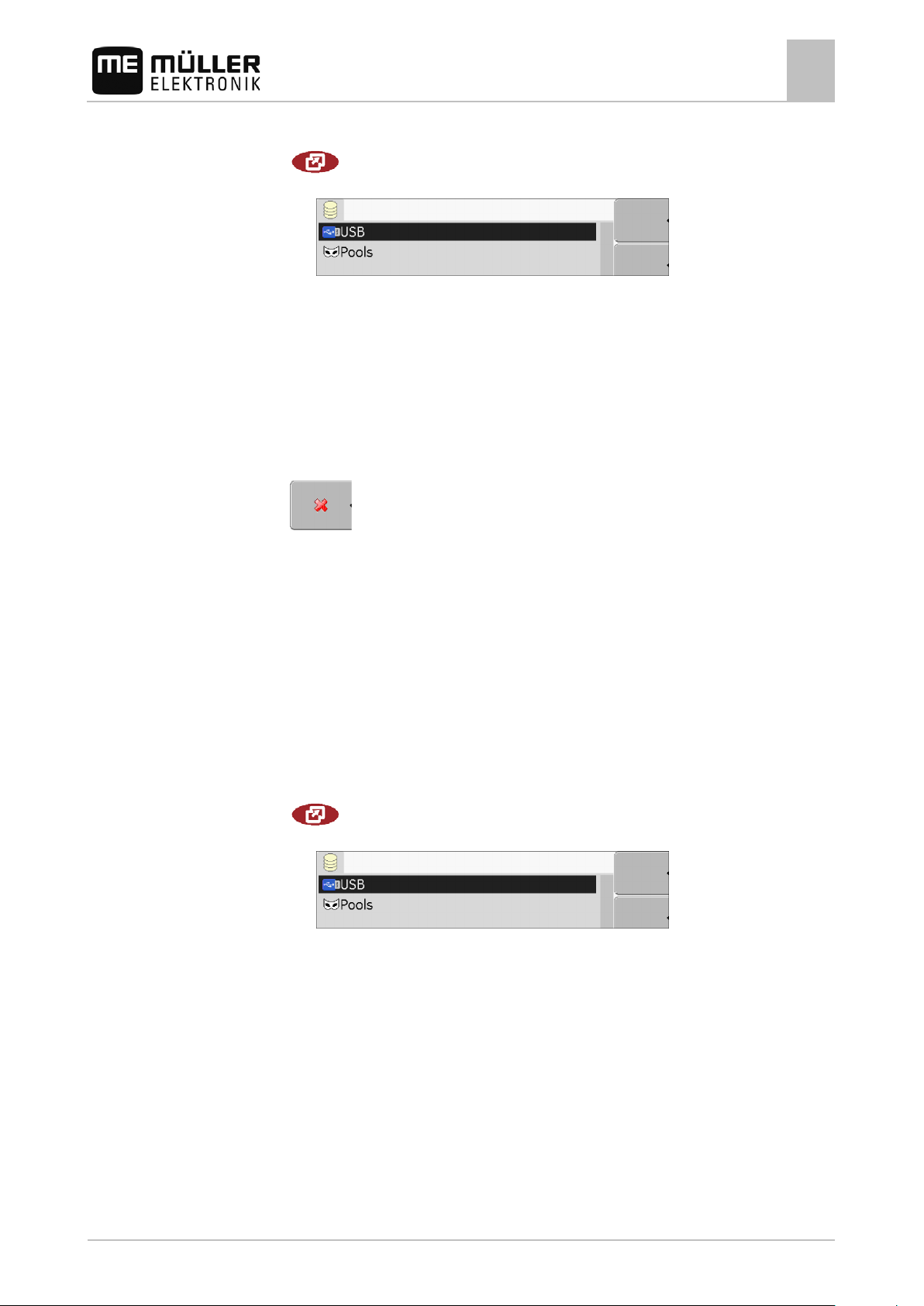
1. Switch to the "Files" screen:
| Service | Files
⇨ The following screen will appear:
2. Click on "USB".
⇨ The "Screencopy" and "Taskdata" folders will appear.
⇨ If these folders fail to appear, it is because you did not create them on the USB flash drive.
3. Click on the desired folder.
⇨ The contents of the folder will be displayed.
A folder may either contain files or further folders.
If nothing is displayed, the folder is empty.
4. Select the files to be deleted.
5.
⇨ Deleting file.
– Delete file (red)
Deleting pools
You can delete the pools to speed up the terminal's operation.
Pools are the intermediate storage for the terminal. Pools are used to temporarily store graphics or
text. Over time, the pools will become too large and slow down the operation of the terminal.
▪ After updating the software of a connected jobcomputer.
▪ If the terminal operates more slowly than usual.
▪ When asked to do so by Customer Services.
1. Switch to the "Files" screen:
| Service | Files
⇨ The following screen will appear:
2. Click on "Pools".
⇨ The names of several folders will appear.
⇨ If the pool is empty, nothing will appear.
3. Click on the desired folder.
30302710-02-EN V7.20141016 47
Page 48

7.16
Procedure
Configuring the terminal in the Service application
7
Activating the "Diagnostics" function
⇨ The contents of the folder will be displayed.
The names of the folders are the ISO IDs of the applications whose temporary data they
store.
4. Select the desired file.
5.
- Delete file.
⇨ Deleting file.
6.
- Restart terminal.
Activating the "Diagnostics" functio n
To activate the "Diagnostics" function, you must first activate its driver.
1. Switch to the "Driver" screen:
| Service | Driver
⇨ The following screen will appear:
2. Click on "Diagnostics".
3. Click on the "DiagnosticsServices" driver.
⇨ Next to the driver the icon
4.
- Restart terminal.
will appear.
⇨ The following function icon will appear on the start screen of the "Service" application:
⇨ You have activated the "Diagnostics" function.
48 30302710-02-EN V7.20141016
Page 49

7.16.1
7.17
7.17.1
Procedure
Configuring the terminal in the Service application
Screenshots
7
Diagnostics
The screen "Diagnostics" contains a variety of information that is primarily important to Customer
Services. Customer Services can use this screen to determine which versions of the hardware and
software are installed on your terminal. This will speed up the diagnostic process if errors arise.
Screenshots
A screenshot is a photo of the screen being displayed.
If an error occurs when you are using the terminal, Customer Services may ask you to capture a
screenshot.
A screenshot can be:
▪ emailed to Customer Services. Email address: service@mueller-elektronik.de
▪ sent to the farmpilot portal (provided you have activated the farmpilot portal)
Configuring the screenshots function
You have activated the "Diagnostics" function. [➙ 48]
1. Start the "Service" application:
| Service |
2.
– Open the "Diagnostics" screen.
3. Click on "Screenshot settings".
4. Click on "Activate screenshots".
⇨ The status of the function is displayed on the icon:
- Function activated
- Function deactivated
5. Click on "Storage location".
⇨ The line will be highlighted with a frame.
6. Select "USB" to save screenshots on the USB flash drive.
7. Select "Portal" to send screenshots to the farmpilot portal.
7.17.2
Procedure
Creating screenshots
You have configured the "Screenshots" function.
If you want to save the screenshots to the USB flash drive, you will already have inserted the
USB flash drive into the terminal.
1. Open any screen.
2. Press the following buttons in the order displayed and keep them pressed for a short while:
(on older terminals you need to press the buttons in reversed order)
30302710-02-EN V7.20141016 49
Page 50

7.18
Configuring the terminal in the Service application
7
CAN-Trace settings
⇨ While the screenshot is being captured, the icon of a photo camera will be displayed in the
centre of the display:
⇨ When the camera icon disappears, the screenshot has been created.
⇨ You will find the screenshot you captured in the location you specified as the "Storage location".
The USB flash drive saves the screenshots in the folder "ScreenCopy".
CAN-Trace settings
CAN-Trace is a function that logs the data exchange between the terminal and the connected
jobcomputers. Customer Services can use the logged data for diagnostic purposes should any errors
arise in the system.
If an error occurs when using the terminal, Customer Services may ask you to activate the CANTrace function.
Procedure
Only activate this function if prompted to do so by Customer Services.
1. Switch to the "CAN-Trace settings" screen:
| Service | | | CAN-Trace settings
2. Click on "Duration (min.)".
3. Set the duration. Specify for how long communication should be logged after the terminal has
been restarted. Communication can be logged for a duration of one to five minutes.
4. Click on "Storage location".
5. Select the storage location.
6. Select "USB" to save data on the USB flash drive. The USB flash drive must be inserted in the
terminal.
7. Select "Portal" to send data to the farmpilot portal. farmpilot must be activated before data can
be transferred.
8. Click on "Activate CAN-Trace".
⇨ The status of the function is displayed on the icon.
⇨ The icon
must appear next to "Activate CAN-Trace".
9.
- Restart terminal.
⇨ After restarting the terminal, CAN-Trace will log the communication between the terminal
and the jobcomputer.
10. Leave the terminal switched on until the set CAN-Trace duration has elapsed.
⇨ The CAN-Trace function will be deactivated automatically.
50 30302710-02-EN V7.20141016
Page 51

NOTICE
◦ Deactivate the farmpilot driver when you are not using the portal.
7.19
7.19.1
Procedure
Configuring the terminal in the Service application
Configuring farmpilot
7
11. If you specified USB as the storage location, verify that the file "StartupTrace.txt" exists on the
USB flash drive:
12. If this file is missing, you must run the CAN-Trace function again.
13. Email the "StartupTrace.txt" file to Customer Services. If you chose "Portal" as the storage
location, this file will have been sent automatically.
Configuring far m pilot
farmpilot is an internet portal which allows software on a farm computer to exchange data with
machines via a mobile phone network. Operating data are stored in a central location on the portal
and are presented clearly to the user.
In order to be able to use the farmpilot portal with your terminal, you must perform the following steps:
▪ Purchase a SIM card and have it activated,
▪ Connect a GSM antenna,
▪ Activate farmpilot,
▪ Enter your farmpilot access data.
Refer to the following chapters to learn how to perform these steps.
Activating farmpilot
To activate farmpilot on your terminal, you must first activate its driver.
High costs from prolonged data transfer
If you do not have a flatrate in your mobile phone contract, continuous use of farmpilot can lead to
high costs.
If your flatrate has a data volume limit, continuous use of farmpilot can quickly use up your data
volume limit.
1. Switch to the "Driver" screen:
| Service | Driver
30302710-02-EN V7.20141016 51
Page 52

7.19.2
Procedure
Parameter
Configuring the terminal in the Service application
7
Configuring farmpilot
⇨ The following screen will appear:
2. Click on "farmpilot".
3. Click on the "farmpilot" driver.
⇨ The following icon will appear next to the driver
4.
- Restart the terminal.
⇨ The following function icon will appear in the start screen of the "Service" application:
⇨ You have activated the farmpilot portal.
You must now enter the access data for the farmpilot portal.
Configuring the connection with farmpilot
Before you can connect the terminal to farmpilot, you must configure the connection.
You will receive this data when purchasing the farmpilot access data.
1. Open the "Service" application:
| Service
2.
- Open the access data screen for farmpilot.
⇨ The following screen will appear:
3. Click on the line with the desired parameter.
4. Configure parameter.
You will require the following parameters for the configuration:
52 30302710-02-EN V7.20141016
Page 53

7.19.3
Parameter
Configuring the terminal in the Service application
Configuring farmpilot
7
Username
User name for farmpilot.
Password
Password for farmpilot.
Provider
Opens a screen where the GPRS connection can be configured.
With most mobile phone providers, this configuration occurs automatically.
If the access data for the GPRS connection differ with your provider, you can configure the
connection manually.
You can find precise instructions in the chapter:
Configuring the GPRS connection manually [➙ 53]
Server
Server address
The server address cannot be altered.
Log
Switches logging on and off.
Switch on logging only when prompted to do so by Customer Services.
Configuring the GPRS connection manually
In this chapter you will learn how to configure the GPRS connection manually.
With most SIM cards, the GPRS connection will be configured automatically.
The GPRS connection must be manually configured in the following instances:
▪ You have bought a new SIM card. The terminal does not recognize your mobile phone provider.
▪ Your mobile phone provider has altered the access data for the GPRS connection.
The values you must enter for the parameters, depend on your mobile phone provider. You can find
out these data from your mobile phone provider.
You will require the following parameters for the configuration:
Country
Country for which the SIM card is configured. Cannot be altered.
Provider
Name of the mobile phone provider. Appears automatically.
With unrecognized cards, you can enter the name of the mobile phone provider yourself.
APN
Abbreviation of "Access Point Name“.
Address of the GPRS access point.
DNS 1 and DNS 2
Abbreviation of "Domain Name System“.
30302710-02-EN V7.20141016 53
Page 54

Function icon
Function
Controls
7.19.4
Configuring the terminal in the Service application
7
Configuring farmpilot
IP addresses of the first and second DNS servers
Number
Dialling code for the modem. Cannot be altered.
Username
User name for the GPRS connection.
Password
Procedure
Password for the GPRS connection.
Retrieve default values.
You can configure the mobile connection as follows:
You have inserted the SIM card.
You have activated the farmpilot portal.
1. Switch to the configuration screen for the GPRS connection:
| | Provider
⇨ The following screen will appear:
2. Set GPRS connection parameters.
Sending diagnostic data to the portal
Customer Services may ask you to send diagnostic data to the portal. This allows Customer Services
Procedure
54 30302710-02-EN V7.20141016
to gather detailed information about your terminal and therefore examine it more thoroughly.
You have activated the "Diagnostics" function.
You have activated the farmpilot portal.
1. Switch to the "Diagnostics" screen:
| Service | | | Diagnostics
2.
- Send diagnostic data.
Page 55

7.20
Procedure
Configuring the terminal in the Service application
Activating the ISO printer
7
⇨ The following notification will appear:
“DeviceidentData transfer“
⇨ The data are being uploaded to the portal.
3. Wait until the "Sending DeviceIdentData" notification disappears.
⇨ The data have been uploaded to the portal.
4. If the process is taking too long, you can cancel the data transfer.
5.
- Cancel data transfer.
Activating the ISO printer
In order to activate the ISO printer, you must activate its driver.
1. Switch to the "Driver" screen:
| Service | Driver
⇨ The following screen will appear:
2. Click on "ISO Printer".
⇨ The installed drivers will appear.
3. Click on the "ISO Printer" driver.
⇨ The following icon will appear next to the driver
4.
- Restart the terminal.
30302710-02-EN V7.20141016 55
Page 56

installed software
icon
8
Tractor-ECU application
8
Activating the ISO printer
Tractor-ECU application
The Tractor-ECU application is used to compile all of the information of the vehicle on which the
terminal is mounted. Tractor-ECU can transfer this information to other apps (e.g. the position of the
GPS receiver to TRACK-Leader or SECTION-Control) or to a connected ISOBUS job computer (GPS
signal as a speed source).
The Tractor-ECU application allows you to:
▪ Create a profile for each vehicle, with specific settings.
▪ Input the sensors which are mounted on the vehicle.
▪ Input the position of the GPS receiver.
If you are using a self-propelled machine, you can simply enter the position of the GPS receiver. [➙
63]
After launching the Tractor-ECU application, the following screen will appear:
Tractor-ECU application start screen
Main area
Displays the current parameters.
Version number
Name of the application and version of the
If the value "…" appears for a parameter on the screen, the relevant sensor is not connected.
Function
Meaning
Calling up a list of vehicles
56 30302710-02-EN V7.20141016
Page 57

green)
8.1
Procedure
8.2
Tractor-ECU application
Add a vehicle profile
8
Add a vehicle profile
List of vehicle profiles
Activated vehicle profile (the icon is marked in
Information on the marked vehicle profile
List of all available vehicle profiles
Function
Meaning
Cursor
icon
Add a vehicle profile
Vehicle profile cannot be deleted
Delete the vehicle profile
Return
1. Call up the Tractor-ECU application:
| Tractor-ECU
2.
3.
- Call up the list of vehicles.
- Add a new vehicle profile.
⇨ A new vehicle profile appears on the screen.
⇨ You can now configure the parameters of the new vehicle profile.
Configuring the parameters for a vehicle profile
In a vehicle profile, you can set the sensors that you want to use.
30302710-02-EN V7.20141016 57
Page 58
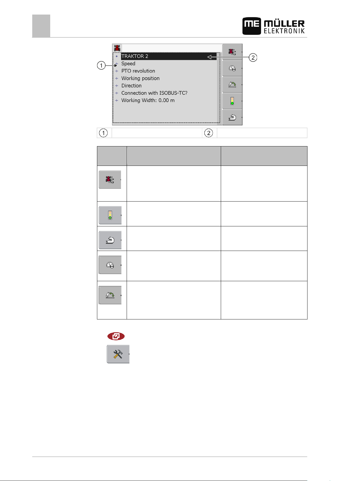
63].
connected to the terminal.
Procedure
Tractor-ECU application
8
Configuring the parameters for a vehicle profile
List of parameters
Function
Meaning Only appears if…
Cursor
icon
Switch to the "Settings" screen
Input the position of the GPS receiver [➙
Activate the vehicle profile The selected vehicle profile is not
activated.
Return
Calibrating the speed sensor
A wheel sensor or radar sensor is used
for speed measurements. The sensor is
Calibrate the working position sensor A hitch sensor - front or a hitch sensor -
rear is used to measure the working
position. The sensor is connected to the
terminal.
1. Call up the Tractor-ECU application:
| Tractor-ECU
2.
- Call up the list of vehicles.
3. Select the vehicle profile.
4. Modify the required parameters. You can also change the name of the vehicle profile.
Parameters in a vehicle profile
Only those parameters which you can use to configure the hardware version of your terminal are
shown.
When configuring sensors, you will need not only to select which sensor is mounted, but also how
this sensor is connected to the terminal.
58 30302710-02-EN V7.20141016
Page 59

Tractor-ECU application
Configuring the parameters for a vehicle profile
8
This can be done in two ways:
▪ A sensor is connected to the terminal via the serial interface (port B). (e.g.: Operating position
sensor, all sensors which can be connected via the 7-pin signal socket). The parameters for the
sensors connected in this way do not have the suffix "via CAN".
▪ A sensor is connected to the ISOBUS and its signal reaches the terminal via the CAN interface
(port A). The parameters for such sensors always have a "via CAN" suffix.
Speed
Configuring the speed sensor. This measures the speed.
Potential values:
▪ "disabled"
No sensor measures the speed.
▪ "Wheel sensor"
A wheel sensor is connected to the terminal. The wheel sensor must be calibrated [➙ 61].
▪ "Radar sensor"
A radar sensor is connected to the terminal. The radar sensor must be calibrated [➙ 61].
▪ "GPS receiver"
The speed is calculated using GPS.
▪ "Unknown sensor via CAN"
A wheel sensor or a radar sensor is connected to the terminal via CAN.
▪ "Radar sensor via CAN"
A radar sensor is connected to the terminal via CAN.
▪ "Wheel sensor via CAN"
A wheel sensor is connected to the terminal via CAN.
PTO revolution
Configuring the PTO (power take-off) revolution sensor. This measures the PTO revolutions.
Potential values:
▪ "disabled"
No sensor measures the PTO revolutions.
▪ "Revol. sensor - front"
A revolution sensor which is fitted onto the front PTO.
▪ "Revol. sensor - rear"
A revolution sensor which is fitted onto the rear PTO.
▪ "Impulses/rev."
Number of impulses which the PTO transfers per revolution.
Working position
With this parameter, you can set whether there is a working position sensor and how its signal
reaches the terminal.
Potential values:
▪ "deactivated"
No sensor measuring the working position.
▪ "Front via connector B"
30302710-02-EN V7.20141016 59
Page 60

Tractor-ECU application
8
Configuring the parameters for a vehicle profile
A working position sensor, is located on the front hitch or on the implement mounted on the front
hitch. It is connected to the terminal via connector B. The working position sensor must be
configured [➙ 62].
▪ "Rear via connector B"
A working position sensor, is located on the rear hitch or on the implement mounted on the front
hitch. It is connected to the terminal via connector B. The working position sensor must be
configured [➙ 62].
▪ "Unknown sensor via CAN"
There is a working position sensor determining the working position of the implement. It is
connected to an ISOBUS job computer or to a different terminal. The signal reaches the terminal
via CAN.
▪ "Front via CAN"
There is a working position sensor determining the working position of the implement at the front
of the vehicle. It is connected to an ISOBUS job computer or to a different terminal. The signal
reaches the terminal via CAN.
▪ "Rear via CAN"
There is a working position sensor determining the working position of the implement at the rear
of the vehicle. It is connected to an ISOBUS job computer or to a different terminal. The signal
reaches the terminal via CAN.
Direction
You can use these parameters to configure whether the terminal can receive a direction signal, and
the source from which it originates. When a direction signal is present, the TRACK-Leader application
can correctly mark the vehicle movement when travelling in reverse.
Potential values:
▪ "deactivated"
No direction sensor is connected to the terminal. If another ISOBUS device transmits a direction
signal, however, this is not blocked.
▪ "Unknown sensor via CAN"
The terminal is receiving a direction signal via CAN whose source is unknown.
▪ "Radar sensor via CAN"
A radar sensor with direction identification is connected to the terminal via CAN.
▪ "Wheel sensor via CAN"
A wheel sensor with direction identification is connected to the terminal via CAN.
▪ "Direction sensor"
A direction sensor is connected to the serial interface of the terminal. Does not function if a
working position sensor is connected to the terminal.
▪ "inversion"
This parameter inverts the meaning of the signals. Only for use with the "Direction sensor"
parameter.
Connection with ISOBUS-TC?
With this parameter, you can set whether the Tractor ECU application should communicate with the
ISOBUS-TC application. In doing so, it transmits: Counters, working position, position of the GPS
receiver.
Deactivate this parameter only if the terminal is used as a secondary terminal and the GPS receiver
is connected to a different terminal.
60 30302710-02-EN V7.20141016
Page 61
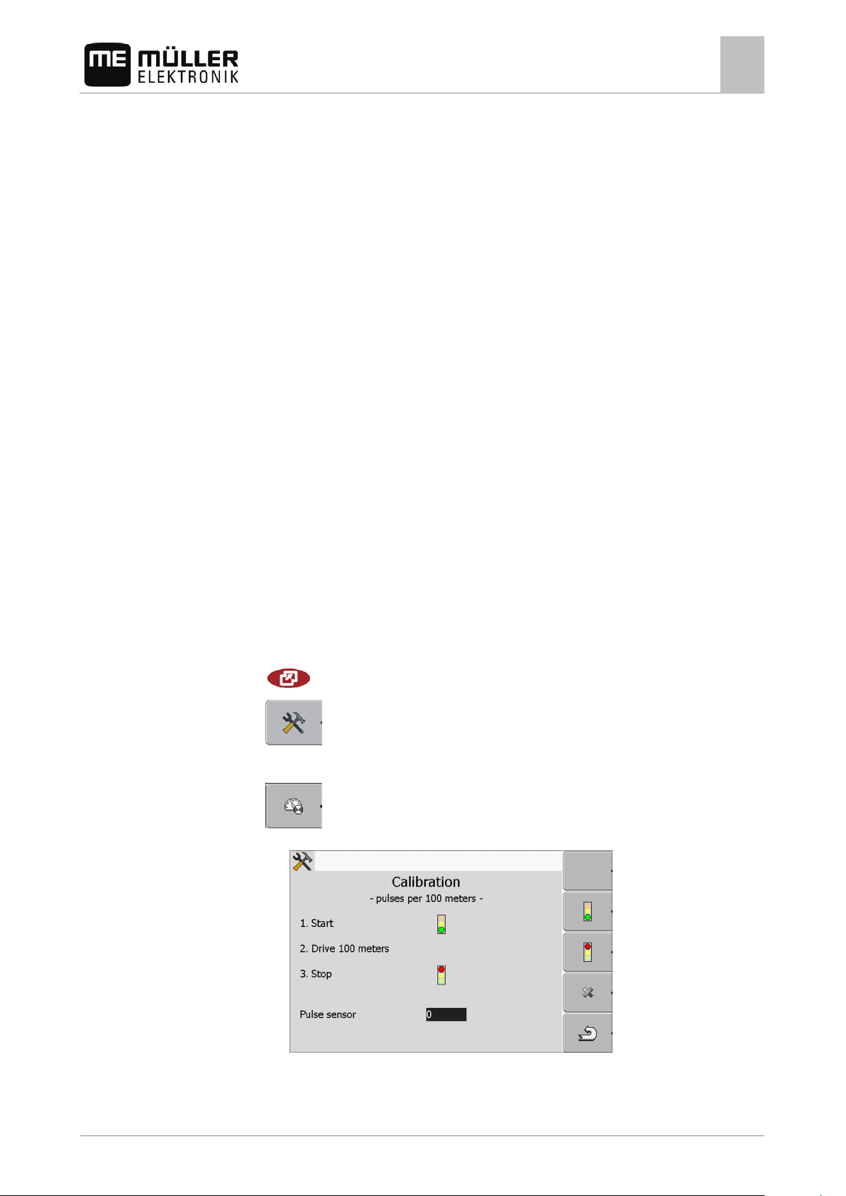
Procedure
Tractor-ECU application
Configuring the parameters for a vehicle profile
8
Working width
This value is transmitted to the ISOBUS-TC application to calculate the processed area.
This parameter primarily enables you to document processed areas for non-ISOBUS implements if
you are working in TRACK-Leader without an ISOBUS job computer, and if you also use the
ISOBUS-TC App simultaneously with ISO-XML tasks.
In this case, no implement data is normally transmitted to ISOBUS-TC. To enable calculation of the
processed areas in the Farm Management Information System at a later time, you can enter the
working width here.
You can only then use this function if you also have an operating position sensor.
Remember to select a different vehicle profile in the tractor ECU after working with a non-ISOBUS
implement, to not always to transfer the working width.
8.2.1
Calibrating the speed sensor
When calibrating the speed sensor using the 328.085ft (100m) method, determine the number of
impulses which the speed sensor encounters over a distance of 328.085ft (100m).
If you know the number of impulses for the speed sensor, you can also input this manually.
You have measured and marked a distance of 328.085ft (100m). The distance must correspond
to the field conditions. You must therefore drive across a meadow or a field.
The vehicle with the connected machine is operational for a 328.085ft (100m) drive and is at the
start of the marked distance.
You have connected a wheel sensor or radar sensor to the terminal.
You have selected the value "Wheel sensor" or "Radar sensor" in the "Speed" parameter.
1. Call up the Tractor-ECU application:
| Tractor-ECU
2.
3. Select the vehicle profile.
- Call up the list of vehicles.
4.
- Press.
⇨ The following screen will appear:
30302710-02-EN V7.20141016 61
Page 62

8.2.2
Tractor-ECU application
8
Configuring the parameters for a vehicle profile
5. When determining using the 100m method: The action sequence is shown on the terminal
OR
For manual input:
6.
⇨ You have calibrated the speed sensor.
- Return to the vehicle profile.
- Enter the desired value.
Configuring a working position sensor
If a working position sensor is connected to the terminal via connector B, you must tell the terminal
the principle according to which the sensor functions.
During the configuration, you can choose between three types of sensor:
▪ "analog"
You are using an analog working position sensor, which measures the height of the hitch linkage
as a percentage.
▪ "digital"
Use this option if the sensor mounted on your equipment is compatible with the Standard ISO
11786. The sensor is connected to the terminal via the signal socket.
▪ "ME-sensor Y"
You are using a working position sensor provided by Müller-Electronik. The sensor is connected
to the terminal.
Procedure
You have connected a working position sensor directly to the terminal or via the signal socket to
the terminal.
You have selected the value "Hitch sensor - front" or "Hitch sensor - rear" in the "Working
position" parameter.
1. Call up the Tractor-ECU application:
| Tractor-ECU
2.
- Call up the list of vehicles.
3. Select the vehicle profile.
4.
- Press.
⇨ The following screen will appear:
5. Select a sensor type.
62 30302710-02-EN V7.20141016
Page 63

to the right of the longitudinal axis
y
before the attachment point
x
after the attachment point
- x
8.2.3
Procedure
Tractor-ECU application
Configuring the parameters for a vehicle profile
8
6. Select whether you want to invert the signal. Inversion only makes sense when you have
selected "digital" or "ME-sensor Y".
7. If you have selected "digital" or "ME-sensor Y":
- Return to the vehicle profile.
OR
If you have selected ”analog“: Move the hitch to the height at which the working position starts.
8.
9.
⇨ You have configured the working position sensor.
Press to confirm.
- Return to the vehicle profile.
Entering the position of the GPS Receiver
When you have mounted and connected the GPS receiver, you must enter its exact position.
For the parallel guide with TRACK-Guide II you can skip this section. You must enter the position of
the GPS receiver in the "Machine profile" screen of the TRACK-Leader application.
If you use TRACK-Guide II with a SECTION-Control box, you must enter the position of the GPS
receiver here.
In order to enter an accurate position for the GPS receiver, you must measure the distances of the
GPS receiver from the longitudinal axis and from the so-called attachment point [➙ 64].
When entering distances, please note that it is essential to specify whether the GPS receiver is to the
left or right of the tractor's longitudinal axis and whether it is positioned before or after the attachment
point.
What is the position of the GPS receiver? The distance should be entered as follows
to the left of the longitudinal axis - y
1. Call up the Tractor-ECU application:
| Tractor-ECU
2.
- Call up the list of vehicles.
3. Select the vehicle profile.
30302710-02-EN V7.20141016 63
4.
- Press.
Page 64

implements
for Offset Y
Procedure
Tractor-ECU application
8
Configuring the parameters for a vehicle profile
⇨ The following screen will appear:
5. Measuring the position of the GPS receiver. You will find out how to do this in the following
subchapters.
6. Input the measured distances in the "Offset X" and "Offset Y" fields.
7.
- Return to the vehicle profile.
⇨ You have input the position of the GPS receiver for the selected vehicle profile.
For machines fitted with an ISOBUS job computer
On the following illustration distances are marked, which must be measured for each different
machine.
GPS receiver for ISOBUS machines
Attachment point for mounted or trailed
Mounted or trailed implements
y Distance between the longitudinal axis and the
GPS receiver
GPS receiver
Self-propelled machines
x Distance for Offset X
To determine the distances for tractors with an ISOBUS-job computer:
64 30302710-02-EN V7.20141016
Page 65

8.3
Procedure
Tractor-ECU application
Activating vehicle profiles
8
The jobcomputer of the farm equipment in use is connected to the terminal
In the jobcomputer the geometry of the farm equipment is configured.
1. Measure the distance between the attachment point of the attached or trailed implement and the
GPS receiver.
2. Input the measured distance as parameter "Offset X".
3. Measure the distance between the longitudinal axis of the machine and the GPS receiver.
Procedure
4. Input the measured distance as parameter "Offset Y".
To determine the distances for self-propelled machines with an ISOBUS job computer:
The jobcomputer of the farm equipment in use is connected to the terminal
In the jobcomputer the geometry of the farm equipment is configured.
1. Input 0 inch as parameter "Offset X".
2. Measure the distance between the longitudinal axis of the machine and the GPS receiver.
3. Input the measured distance as parameter "Offset Y".
Activating vehicle profiles
In order to work with the inserted parameters, you must activate the vehicle profile of the used
vehicle.
1. Call up the Tractor-ECU application.
| Tractor-ECU
2.
3. Select the vehicle profile.
- Call up the list of vehicles.
4.
30302710-02-EN V7.20141016 65
- Activate the vehicle profile.
Page 66

9
9.1
9.2
Procedure
ISOBUS-TC task processing
9
Using ISOBUS-TC
ISOBUS-TC task processing
Using ISOBUS-TC
The ISOBUS-TC application is an application from Mueller-Electronics which establishes an interface
between the ISOBUS job computer, the TRACK-Leader application and the FMIS (Farm
Management Information System) on the ISOBUS terminal.
With ISOBUS-TC, you can:
▪ Plan and edit ISO-XML tasks on the terminal,
▪ Edit ISO-XML tasks which you have planned on the PC using your FMIS.
All information contained in the order will be transferred by ISOBUS-TC to specialized applications of
the terminal. This means that each application is doing exactly what it can do best:
▪ The position of the field is transferred to FIELD-Nav. It can therefore navigate the vehicle directly
to the field.
▪ The field boundaries, guidance lines, prescription maps and other information about processed
fields stored in the task are transferred to TRACK-Leader. The field can be therefore processed.
▪ The target rates are transferred from a prescription map to the ISOBUS job computer. In this
way, you do not have to worry about inputting the target rates.
▪ ISOBUS-TC documents work duration, and the persons, implements and resources involved.
Adjusting how you use ISOBUS-TC
First of all, you must decide how you will use the ISOBUS-TC application. The operation of ISOBUSTC and TRACK-Leader is dependent on this setting.
There are two scenarios in which you can use ISOBUS-TC. Use the "Work with ISO-XML?"
parameter to set the scenario you will work with:
▪ "Yes"
Select this setting if you set up tasks on your PC or if you want to set up tasks on the terminal.
In this instance, you must always start a task before you start work. Only then does the data
exchange between ISOBUS-TC, TRACK-Leader and the ISOBUS-job computer function.
You will need a "ISOBUS-TC" license for this.
▪ "No"
Select this setting if you do not use tasks. Instead, you use application maps in shp format or
enter the application rates directly into the ISOBUS-job computer.
In this instance, ISOBUS-TC only works in the background. You will not need a license for this.
You can also skip the other sections of the instructions regarding ISOBUS-TC.
You can change the mode of the "ISOBUS-TC" application as follows:
1. Change to "Settings" screen:
| ISOBUS-TC |
66 30302710-02-EN V7.20141016
Page 67

Tractor-ECU application of the terminal.
9.3
Procedure
ISOBUS-TC task processing
Configuring the list of connections
9
⇨ The following screen will appear:
2.
- Select and click on the "Work with ISO-XML?" line.
⇨ The mode will change with each click.
3. Set the desired mode.
- Restart the terminal.
4.
⇨ The set mode will be activated after restart.
Configuring the lis t of c onne c tions
The list of connections indicates the ISOBUS job computers from which the terminal will load the
geometries of the connected implements. This geometry is required in order to calculate the position
of all implement components on the basis of the GPS signal. Only in this way are precise parallel
driving and section switching possible.
30302710-02-EN V7.20141016 67
The farm equipment must be ordered consecutively from the front to the rear when viewed in the direction of
travel
Tractor ECU of the terminal.
Connectors between the "ME-Tractor-ECU"
application and "ME_ISO_Spritze". The
geometries of this equipment is transferred to
SECTION-Control.
Name of the job computer
Not all of the equipment in the list must be
connected. Job computers which contain no
relevant geometric data can be disconnected.
In the image, the "Tractor" job computer has
been the disconnected, as the tractor
geometry should be transferred from the
ISOBUS job computer "ME_ISO_Spritze"
If you are not using the ISOBUS-TC application, you can configure the list of connections as follows:
All ISOBUS job computers are connected to the ISOBUS.
Page 68

ISOBUS-TC task processing
9
Configuring the list of connections
1. Open the ISOBUS-TC application.
2.
– Open the screen with the list of connection.
⇨ The following screen will appear:
⇨ A list will appear with all of the equipment connected to the ISOBUS. The connectors
appear between the equipment.
3.
- Press the rotating knob in the top row in order to select the first device. If you are
using an ME terminal to which a GPS receiver is connected, insert the ME-Tractor-ECU
application in the top row. If another terminal or tractor job computer contains the geometry, you
can set this.
4. The agricultural implement which is connected to the rear ISOBUS socket should appear in the
second line. Select a device in the row for the second device.
5. You now only need to select the appropriate connector between the two devices. Press the
rotating knob in the line between two devices and select the appropriate connector for each
device.
In simple systems, the terminal can set up the list of connections automatically. In particular, when
the ME terminal is the only unit which contains the tractor geometry (see: Entering the position of the
GPS Receiver [➙ 63]
It can however still be necessary to set the list of connection manually in the following instances:
▪ If a tractor job computer (Tractor-ECU), in which the tractor geometry is saved, is mounted as an
independent job computer on the tractor. In this instance, you must decide which Tractor-ECU is
connected in the list of connections with other equipment: the application on the ME terminal or
on the tractor job computer.
▪ If the system cannot organize the ISOBUS job computer by itself. For example when more than
one implement is connected to the tractor (e.g.: slurry tanker and planter/seeder).
▪ When the connection to an ISOBUS job computer is interrupted during the start-up of a ISO-XML
task. In most cases, the list of connections will be set correctly as soon as you reconnect the
ISOBUS job computer.
▪ If this error message appears when starting the terminal: "List of connection is incomplete."
▪ When the following error message appears when starting a navigation in TRACK-Leader: "The
device data is still loading." The settings in the list of connections can eliminate this problem.
68 30302710-02-EN V7.20141016
Page 69

Manufacturer
On-board computer
Software version
Baud rate
RAUCH
Quantron E
V3.51.00
9600
RAUCH
Quantron E2
V2.10.00
9600
RAUCH
Quantron S
V3.90.00
9600
RAUCH
Quantron S2
V1.00.05
9600
10
10.1
Serial Interface application
Transfer target rates via LH5000
10
Serial Interface application
The "Serial Interface" application is used to enable communication between the terminal and a nonISOBUS compatible on-board computer.
This interface enables you to use all of the applications together with the GPS signal and the onboard computers, in order to:
▪ Transfer target rates (using the LH-5000 protocol or the ASD protocol); [➙ 69]
▪ Switch sections on and off (using the ASD protocol). [➙ 70]
So that you do not need to reconfigure the application each time, you can create an individual profile
for each on-board computer.
Transfer target rates via LH5000
Procedure
Tested on-board computer*
RAUCH Quantron A V1.20.00 9600
ME Spraylight V02.00.10 9600
* - Only on-board computers on which we were able to determine that the serial interface was
functional are listed. Results may differ with different software versions.
You have checked whether you need to activate the LH5000 protocol on the on-board computer.
If yes, you have activated the protocol.
1. Connect the on-board computer to the terminal. [➙ 16]
30302710-02-EN V7.20141016 69
2.
- Switch on the terminal.
3. Open the Serial Interface application:
| SerialInterf
4.
5.
- Open the list of machine profiles.
- Add a new machine profile.
⇨ A new machine profile appears on the screen.
6. Configure the parameters as shown in the following steps.
7. "Operating Mode" -> "Target Rate Transfer"
8. "Protocol" -> "LH5000"
Page 70

play/controller
Amazone
Amatron+
V3.23.00
19200
+
-
RAUCH
Quantron A
V1.20.00
19200** - +
RAUCH
Quantron E2
V2.10.00
19200** + +
Elektronik
10.2
Serial Interface application
10
Switching sections and transferring target rates via ASD
9. "Implement type" -> Select the implement with which you are working.
10. "Baud rate" -> normally "9600". The baud rate is dependent on the on-board computer.
11.
12.
13.
- Activate the machine profile.
- Press and confirm in order to save the machine profile.
- Restart the terminal.
Further steps
You have set up the serial interface. You must now configure the applications of the terminal.
In the TRACK-Leader application:
1. Deactivate the "SECTION-Control" parameter under "Settings / General".
2. Create a ag equipment profile for the combination of your tractor and mounted implement.
3. Load a prescription map.
You can load the prescription map in two ways:
▪ As a shp file, in the TRACK-Leader application.
▪ As part of a ISO-XML task, if you are using the ISOBUS-TC application and a FMIS.
For more information, please refer to the TRACK-Leader and ISOBUS-TC operating instructions.
Switching sections and transferring target rates via ASD
Tested on-board integrated display/contr oll er s*
Manufacturer On-board dis-
Amazone Amatron3 V1.09.00 19200 + -
RAUCH Quantron E V3.51.00 19200** + +
Müller-
Spraylight V02.00.13 19200 + +
Elektronik
Müller-
DRILL-Control - 19200 + +
Software version Baud rate Target rate transmission Section control
* - Only on-board integrated display/controllers are listed for which we were able to determine that the
serial interface was functional. Results may differ with different software versions.
** - "GPS Control" must be activated on the on-board integrated display/controller
70 30302710-02-EN V7.20141016
Page 71

Procedure
Serial Interface application
Switching sections and transferring target rates via ASD
10
You can use the ASD protocol to transfer target rates to a prescription map or to switch sections. The
degree to which you can use these functions will depend on the on-board computer.
In order to be able to perform transfers using the ASD protocol, you will need to activate the "ASDProtocol" license.
To configure the serial interface in order to switch sections using your on-board integrated
display/controller:
You have activated the "SECTION-Control" parameter in the "General" menu of the TRACK-
Leader application.
You have checked whether you need to activate the ASD protocol on the on-board integrated
display/controller. If yes, you have activated the protocol.
1. Connect the on-board integrated display/controller to the terminal. [➙ 16]
2.
- Switch on the terminal.
3. Call up the SerialInterface application:
| SerialInterf
4.
5.
- Open the list of implement profiles.
- Add a new implement profile.
⇨ A new implement profile appears on the screen.
6. Configure the parameters as shown in the following steps.
7. "Operating Mode" - "Section switching"
8. "Protocol" - "ASD"
9. "Implement type" - Select the implement with which you are working.
10. "Tractor<-->Working point" - Here, enter the distance between the suspension point of the tractor
and the working point.
11. "Offset L/R" - This parameter is used to set the geometry of asymmetrical implements. Here,
input the distance by which the middle of the working width should be shifted. For a shift to the
30302710-02-EN V7.20141016 71
Page 72

Serial Interface application
10
Switching sections and transferring target rates via ASD
right, enter a positive value, and for a shift to the left, enter a negative value.
12. "Working Width" - The working width set in the on-board integrated display/controller.
13. "No. of sections" - The number of sections set in the on-board integrated display/controller.
14.
- The width of the individual sections set in the on-board integrated
display/controller.
15.
16.
17.
18.
- Back.
- Activate the implement profile.
- Press and confirm to save the implement profile.
- Restart terminal.
Further steps
You have set up the serial interface. You must now configure the applications of the terminal.
In the TRACK-Leader application:
1. Activate the "SECTION-Control" parameter under "Settings / General".
2. Configure the section switching in "Settings/ SECTION-Control".
3. Load a prescription map.
You can load the prescription map in two ways:
▪ As a shp file, in the TRACK-Leader application.
▪ As part of a ISO-XML task, if you are using the ISOBUS-TC application and a FMIS.
For more information, please refer to the TRACK-Leader and ISOBUS-TC operating instructions.
72 30302710-02-EN V7.20141016
Page 73

11
Procedure
File Server application
11
File Server application
The File Server application is used to define a save location on the terminal. This save location can
be used by all ISOBUS implements which do not have their own USB interface. This enables the
updating of certain ISOBUS job computers, and also the possibility of saving, for example protocols
or error messages.
A "Fileserver" folder is created for this purpose on the hard disk of the terminal. All ISOBUS
implements can access this folder, and write or read data there.
The folder has a maximum disk space of 5 MB.
If you want to copy files to the terminal, these must be on your USB memory device, in the
"Fileserver" folder.
1. Call up the Fileserver application:
| Fileserver
⇨ The application starts screen will appear.
2.
3.
4.
- Press.
- Copy files from the USB memory device to the terminal (Import).
- Copy files from the terminal to the USB memory device (Export).
⇨ One of the following messages will appear: "Start import?" or "Start export?".
5. Click "Yes" to confirm.
⇨ The data will be copied.
⇨ A report will appear.
6. Confirm using "OK".
⇨ You have successfully imported or exported the data.
30302710-02-EN V7.20141016 73
Page 74

NOTICE
12
12.1
12.2
12.3
Selecting components
Maintenance and servicing
12
Servicing and cleaning the terminal
Maintenance and servicing
This product does not contain any components which require maintenance or repair!
Never unscrew the casing!
Servicing and cleaning the terminal
▪ Press the keys with your fingertips. Avoid using your finger nails.
▪ Only clean the product with a soft, damp cloth.
▪ Only use clear water or glass cleaner.
Disposing of the unit
When it has reached the end of its service life, please dispose of this product as
electronic scrap in accordance with applicable EU legislation.
Instructions on retrofitting
Instructions on how to retrofit electrical and electronic farm equipment and/or
components
User responsibility
Additional requirements
Agricultural equipment used today features electronic components and parts whose function can be
affected by other farm equipment which emits electromagnetic waves. Such effects could lead to
personnel being put in danger, if the following safety instructions are not adhered to.
When selecting components, make sure first of all that the retrofitted electrical and electronic
components comply with the current version of the EMC Directive 2004/108/EC and carry the CE
marking.
When retrofitting a machine with electrical and electronic farm equipment and/or components
connected to the vehicle's electrical system, it is your own responsibility to check whether the
installation causes interference with the vehicle's electronic system or other components. This
applies, in particular, to the electronic control of:
▪ electronic hitch control (EHR),
▪ front linkage,
▪ power take off (PTO),
▪ engine,
▪ gear.
The following requirements must be met in order to retrofit mobile communication systems (e.g. radio,
phone):
▪ All farm equipment must be approved and installed in accordance with the regulations applicable
in the respective country.
▪ The equipment must be installed as a fixed installation.
▪ The operation of portable or mobile farm equipment in the interior of the vehicle is only permitted
via a connection to a permanently installed exterior antenna.
▪ The transmitting part must be spatially separated from the vehicle's electronic system.
74 30302710-02-EN V7.20141016
Page 75

Parameter
Value
Operating temperature
-20 - +70 ℃
Weight
1.3 kg
Dimensions (W x H x D)
220 x 210 x 95 mm
EMC
In accordance with ISO 14982 / PREN 55025
and without external devices.
modem and without external
12.4
Procedure
12.5
12.5.1
Maintenance and servicing
Checking the software version
12
▪ When attaching the antenna, pay attention to proper installation, including a sound ground
connection between the antenna and the vehicle's ground wire.
For information on wiring and installation as well as the maximum allowable current consumption,
please also refer to the installation guide provided by the machine manufacturer.
Checking the software version
1. Open the "Service" application:
| Service
2. The following screen will appear:
3. The software version can be found below the ME logo.
Technical specifications
Technical specifications of the terminal
Operating voltage 10 - 30 V
Storage temperature -30 - +80 ℃
Protection class IP 54 in accordance with DIN 40050/15
ESD protection In accordance with 10605
Power input For terminal without GSM modem
Typically: 0.4A at 13.8 V
30302710-02-EN V7.20141016 75
For terminal with embedded GSM
Typically: 0.5A at 13.8 V
Page 76

Parameter
Value
devices.
Processor
32-bit ARM920T up to 400 MHz
Boot USB
128 MB
Keyboard
17 keys plus rotary knob.
2 x M12 for two analog cameras (optional)
Pin no.:
Signal:
Pin no.:
Signal
2
CAN_L1
7
CAN_H1
3
CAN_GND1
8
CAN_EN_out2
5
CAN_EN_in
12.5.2
Maintenance and servicing
12
Technical specifications
Display VGA TFT color display; display size (diagonal): 14.5 cm ; resolution:
640 x 480 pixels
RAM 64 MB SDRAM
Internal clock Buffered by capacitor, keeps the time for 2 weeks without an external
power supply.
Outputs 2 x CAN
1 x USB 1.1
2 x RS232. Second RS232 with restricted functionality.
Pin assignment of port A
Port A is a 9-pin D-sub port of the ISO agricultural machinery interface (CAN).
1 CAN_L 6 - Vin1 (GND)
4 CAN_H 9 + Vin1
76 30302710-02-EN V7.20141016
Legend:
+Vin = voltage supply (+)
–Vin = ground (-)
1)
- Signals marked with 1 correspond to the CiA assignment (CAN in automation).
1
Both signals CAN_L and CAN_L
and/or CAN_H and CAN_H1 are linked internally and used to loop
the CAN bus through.
Assigning CAN_EN_in to the supply potential (= +Vin) enables the terminal to be switched on.
The signals '-Vin' and 'CAN_GND' are directly linked with both connectors, therefore it is crucial to
avoid differences in potential between the pins of these two connectors.
Page 77

Purpose
Pins used
As second serial interface
2, 3, 4, 5
signal.
Pin no.:
Signal:
Pin no.:
Signal
1
Wheel sensor1
6
PTO2
2
/RxD
7
CAN_H
driving direction
4
Voltage supply for GPS receiver4
9
CAN_L
5
GND
12.5.3
Maintenance and servicing
2)
is compliant with TBC_Pwr in ISO 11783. When the terminal is switched on, this pin is under
voltage (supply voltage minus approx. 1.2V).
Technical specifications
12
Pin assignment of port B
The pin assignment of port B is dependent on the hardware version of the terminal.
Terminals with hardware versions from 3.0.0
9-pin. D-Sub connector
Port B is a 9-pin D-Sub port.
The connector can be used for the following purposes depending on its assignment:
As second CAN interface 7, 9
As signal input for two digital and one analog
Pin assignment of port B
1, 5, 6, 8
3 /TxD 8 Working position sensor3 or
Reverse signal for determining the
30302710-02-EN V7.20141016 77
Legend:
1
) Digital input as per: ISO 11786:1995 chapter 5.2
2
) Digital input as per: ISO 11786:1995 chapter 5.3
3
) Digital input as per: ISO 11786:1995 chapter 5.5
4
) The pin is switched in parallel with pin 4 by port C. Total loading is 600mA.
Page 78

CAUTION
Pin no.:
Signal
2
/RxD
3
/TxD
5
GND
6
DSR
7
RTS 8 CTS
12.5.4
Maintenance and servicing
12
Technical specifications
Pin assignment of port C
Port C is an RS232 interface
Damage to the equipment caused by short circuit
Pin 4 of port C is live. The voltage depends on the operating voltage of the terminal and is used to
supply the DGPS Receiver from Müller Elektronik.
Other GPS Receivers may suffer damage if connected to this port.
Before connecting a different GPS Receiver:
◦ Check what voltage the terminal is connected to (12 V or 24 V).
◦ Check the pin assignment of the GPS Receiver.
◦ Check the allowable voltage for the GPS Receiver.
◦ Compare the terminal voltage to the allowable voltage for the GPS Receiver.
◦ Compare the pin assignment.
◦ Only connect the GPS Receiver to the terminal, if the voltage range and pin assignment of both
devices don't differ from each other.
Pin assignment of port C
1 DCD
4 Voltage supply for GPS receiver1
9 RI (+5 V)
Legend:
1
) The pin is switched in parallel with pin 4 by port B. Total loading is 600mA.
When switched on, the terminal routes current to the farm equipment that is connected via the RS232
connector. The voltage of the RS232 connector is dependent on the operating voltage of the terminal.
When connected to a 12 V battery, the terminal will transfer approx. 11.3 V to the connected
equipment.
78 30302710-02-EN V7.20141016
Page 79

the terminal)
Pin
Signal
2
GND
4
Video signal
5
Video screen
12.5.5
Maintenance and servicing
Technical specifications
12
When connected to a 24 V battery, the terminal will transfer approx. 23.3 V to the connected
equipment.
The use of a GPS Receiver only requires the signals RxD and TxD as well as GND.
Pin assignment of camera ports 1 and 2
Ports 1 and 2 are used to connect an analogue camera. The pin assignment is identical for both
ports.
Ports 1 and 2 are 5-pin, A-encoded M12 sockets. Please refer to the following table for the pin
assignment.
Pin assignment of the socket (in
Pin assignment of the connector
1 Pin is exclusively intended for use by ME (do not connect anything)
3 Pin is exclusively intended for use by ME (do not connect anything)
Outer sheathing Screen
30302710-02-EN V7.20141016 79
Page 80

13
13
Notes
Notes
80 30302710-02-EN V7.20141016
 Loading...