

Page 1

Installation and operating instructions
SLURRY-Controller 3.0
Version: V4.20191001
30322453-02-EN Read and follow these instructions. Keep these instructions in a
safe place for later reference. Please note that there might be a
more recent version of these instructions on the homepage.
Page 2

Document
Copyright ©
Company details
Installation and operating instructions
Product: SLURRY-Controller 3.0
Document number: 30322453-02-EN
As of software version: 03.04.11.XX
Original instructions
Original language: German
Müller-Elektronik GmbH
Franz-Kleine-Straße 18
33154 Salzkotten
Germany
Phone: ++49 (0) 5258 / 9834 - 0
Fax: ++49 (0) 5258 / 9834 - 90
Email: info@mueller-elektronik.de
Homepage: http://www.mueller-elektronik.de
Page 3

30322453-02-EN
V4.20191001
3
1
For your safety
6
1.1
Basic safety instructions
6
1.2
Intended use
6
1.3
Layout and meaning of warnings
6
1.4
Safety stickers on the product
7
1.5
Disposal
7
1.6
EU declaration of conformity
7
2
About the job computer
9
2.1
Job computer functions
9
2.2
System overview
9
2.3
Rating plate
11
3
About these Operating Instructions
12
3.1
Who is the target user for these Operating Instructions?
12
3.2
Directional information in these instructions
12
3.3
Layout of operating instructions
12
3.4
Layout of references
12
4
Mounting and installation
13
4.1
Installing the job computer
13
4.1.1
Selecting the installation site
13
4.1.2
Connecting the AMP connectors
13
4.1.3
Separating the AMP connectors
13
4.2
Connecting the job computer to the ISOBUS
14
4.3
Installing the junction box
15
4.3.1
Connecting the sensors and actuators to the junction box
15
4.3.2
Inserting the cable core into a terminal
16
4.3.3
Connecting the junction box to the job computer
16
4.4
Installing sensors on the slurry tanker
16
4.4.1
Installing the rotational speed sensors
17
4.4.2
Installing the speed and position sensors
17
4.4.3
Installing the pressure sensors
19
4.4.4
Installing the flow meter
20
4.5
Installing actuators on the slurry tanker
21
4.5.1
Installing linear actuators
21
5
Basic control principles
23
5.1
Switching on the job computer
23
5.2
Layout of work screen
23
5.3
Navigation in the software
24
Table of contents
Table of contents
Page 4

4
V4.20191001
30322453-02-EN
6
Operating job computer on the field
26
6.1
Controlling the application
26
6.1.1
Setting target rate
26
6.1.2
Starting and stopping the application
26
6.1.3
Opening and closing the application valve
28
6.1.4
Adjusting the target rate during operation
28
6.1.5
Operating section valves
29
6.1.6
Spreading the slurry evenly across the working width
30
6.1.7
Operating the drop stop
31
6.2
Filling the slurry tanker
32
6.2.1
Moving the filling arms
33
6.2.2
Opening and closing the valves
34
6.2.3
Increasing the filling speed
35
6.2.4
Chopping up foreign objects in the slurry
36
6.3
Operating the mounted implement
36
6.3.1
Folding the booms of a mounted implement
36
6.3.2
Adjusting the lower link position
37
6.4
Adjusting the chassis
38
6.4.1
Adjusting the drawbar position
38
6.5
Switching the lighting on and off
39
6.6
Viewing the assignment of the joystick
39
6.7
Documenting work results
40
6.7.1
Trip counter
40
6.7.2
Customer-specific total counter
41
6.7.3
Implement counter
43
7
Configuring the job computer for work
44
7.1
Entering the geometry
44
7.1.1
“Min. working speed” parameter
45
7.1.2
“Delay - Sequence” parameter
45
7.1.3
“Delay on start” parameter
45
7.1.4
“Delay on stop” parameter
45
7.2
Selecting and configuring the speed source
45
7.2.1
Using the speed signal from the tractor
45
7.2.2
Calibrating the speed sensor with the 100m method
46
7.2.3
Entering the simulated speed
46
7.3
Calibrating the flow meter
47
7.3.1
“Correction Factor” parameter
48
7.3.2
“Flow Meter Impulses” parameter
48
7.4
Configuring the fill level sensor
48
7.5
Configuring sections
49
7.6
Configuring the mounted implement
50
7.6.1
“Mounted Implement” parameter
50
7.6.2
“Number of Sections” parameter
50
7.6.3
“Working Width” parameter
50
7.6.4
“Fold/Unfold” parameter
51
Table of contents
Page 5

30322453-02-EN
V4.20191001
5
7.7
Configuring the tank
51
7.7.1
“Tank Size” parameter
51
7.7.2
“Alarm Fill Level” parameter
51
7.7.3
“Min Auto Speed” parameter
51
7.7.4
“Delay - Level Sensor” parameter
51
7.7.5
“Correction Factor” parameter
51
7.8
Configuring the units
51
7.8.1
“No. of Dec. Places” parameter
52
7.8.2
“Decimal (fixed)” parameter
52
7.9
Configuring external operating devices
52
7.9.1
“Joystick” parameter
52
7.10
Entering the password
52
7.11
Activating licenses
52
8
Troubleshooting
54
8.1
Alarm messages
54
8.2
Checking the software version
57
8.3
Compatibility
58
8.3.1
Compatibility between terminal and job computer
58
8.3.2
Compatibility with ISOBUS terminals
58
9
Technical specifications
59
9.1
Technical specifications of the job computer
59
9.2
Available languages
59
10
Spare parts
61
Table of contents
Page 6

6
V4.20191001
30322453-02-EN
1
1.1
1.2
1.3
For your safety
1
Basic safety instructions
For your safety
Basic safety instructions
Be sure to always comply with the following instructions during operation:
▪ Read the operating instructions to the agricultural device which you want to control by using the
product.
▪ Before you leave the vehicle cab, ensure that all automatic mechanisms are deactivated or
manual mode is activated.
▪ Keep children away from the implement and the job computer.
Servicing
Keep the system in a functional condition. To do so, follow these instructions:
▪ Do not make any unauthorized modifications to the product. Unauthorized modifications or use
may impair safety and reduce the service life or operability of the unit. Modifications are
considered unauthorized if they are not described in the product documentation.
▪ Never remove any safety mechanisms or stickers from the product.
▪ Before charging the tractor battery, always disconnect the tractor from the job computer.
▪ The product does not include any user-serviceable parts. Do not open the casing. If the casing is
Operation
opened, its imperviousness can be changed.
Intended use
The product is only intended for use in the agricultural sector. The manufacturer is not liable for any
other installation or use of the product.
The manufacturer cannot be held liable for any personal injury or property damage resulting from
such non-compliance. All risk arising from improper use lies with the user.
Intended use also includes compliance with the conditions for operation and repairs prescribed by the
manufacturer.
All applicable accident prevention regulations and all other generally recognized safety, industrial,
and medical standards as well as all road traffic laws must be observed. Any unauthorized
modifications made to the equipment will void the manufacturer's warranty.
Layout and meaning of warnings
All safety instructions found in these Operating Instructions are composed in accordance with the
following pattern:
Page 7
30322453-02-EN
V4.20191001
7
WARNING
physical injury, if not avoided.
CAUTION
damage to property, if not avoided.
NOTICE
This signal word identifies hazards that could potentially cause damage to property, if not avoided.
Example
1.4
1.5
1.6
For your safety
Safety stickers on the product
1
This signal word identifies medium-risk hazards, which could potentially cause death or serious
This signal word identifies hazards that could potentially cause minor or moderate physical injury or
There are some actions that need to be performed in several steps. If there is a risk involved in
carrying out any of these steps, a safety warning appears in the instructions themselves.
Safety instructions always directly precede the step involving risk and can be identified by their bold
font type and a signal word.
1. NOTICE! This is a notice. It warns that there is a risk involved in the next step.
2. Step involving risk.
Safety stickers on the product
Sticker on the job computer
Do not clean with a high-pressure cleaner.
Disposal
When it has reached the end of its service life, please dispose of this product as
electronic scrap in accordance with all applicable waste management laws.
EU declaration of conformity
Herewith we declare that the design and construction of this product and its identical variants, as well
as the form brought onto the market by us, is in accordance with the relevant safety and health
requirements of the EU Directive of Electromagnetic Compatibility 2014/30/EU. If alterations are
made to the product without prior consultations with us, this declaration becomes invalid.
Page 8

8
V4.20191001
30322453-02-EN
(EMC Directive 2014/30/EU)
In conformity with further EU directives:
Directive 2011/65/EU (RoHS 2)
For your safety
1
EU declaration of conformity
MIDI 3.0 job computer
Harmonised standards applied: EN ISO 14982:2009
Page 9
30322453-02-EN
V4.20191001
9
2
2.1
2.2
About the job computer
About the job computer
Job computer functions
2
Job computer functions
The ECU-MIDI slurry tanker job computer is an ISOBUS job computer that can control the operation
of slurry tankers.
The ISOBUS job computer is the control central of the slurry tanker. Several sensors are connected
to the job computer, which monitor important implement parts. The job computer controls the
implement based on these signals and on the operator's specifications. An ISOBUS terminal serves
as an interface. All implement-specific data is stored in the job computer and is therefore maintained
even when changing the terminal.
Among other things, the job computer can perform the following tasks:
▪ Control of various implements
– Arable injector
– Grassland injector
– Trailing hose distributor
– Trailing shoe distributor
– Splash plate
▪ Control of all hydraulic functions
▪ Control of up to 18 sections
▪ Control of various filling arms (front, top, side)
▪ Monitoring of the application
▪ Control of the tramline valves
▪ Control of a tyre inflation system
▪ Monitoring of the steering system
▪ Various speed sources
▪ Application and filling using defined sequences
System overview
The system consists of one or several job computers that are mounted on the slurry tanker and
control the operation.
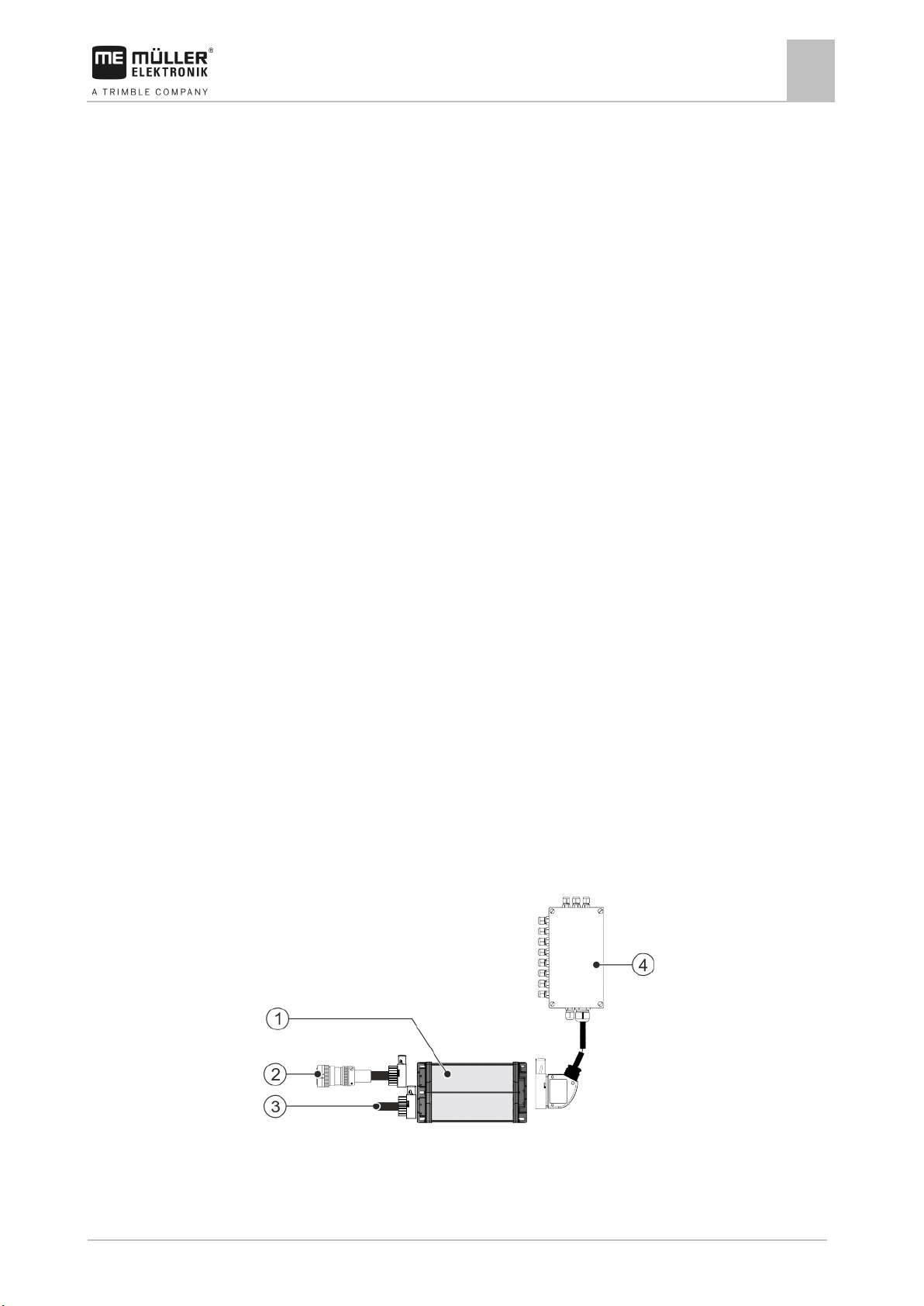
Small system with one job computer
Page 10
10
V4.20191001
30322453-02-EN
CAN termination
About the job computer
2
System overview
ECU-Midi job computer
Junction box
ISOBUS cable
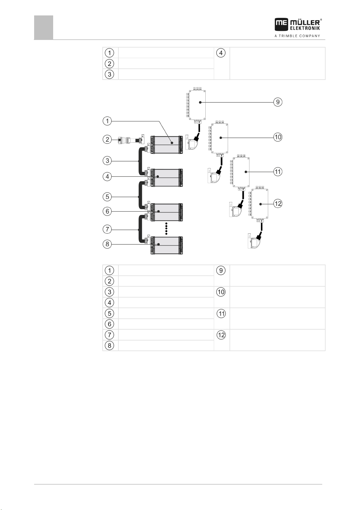
Large system with 4 job computers, max. 7 job computers are possible
1. ECU-Midi job computer
Junction box 1st Job computer
ISOBUS cable
Connecting cable between the job computers
Junction box 2nd Job computer
2. ECU-Midi job computer
Connecting cable between the job computers
Junction box 3rd Job computer
3. ECU-Midi job computer
Connecting cable between the job computers
Junction box 4th Job computer
4th ECU-Midi job computer
Each job computer is responsible for controlling selected functions of the slurry tanker and receives
signals from selected sensors. For systems with multiple job computers, identical job computers and
junction boxes are used respectively.
In the slurry tanker configurator, you can see which sensors and actuators can be connected to the
junction box.
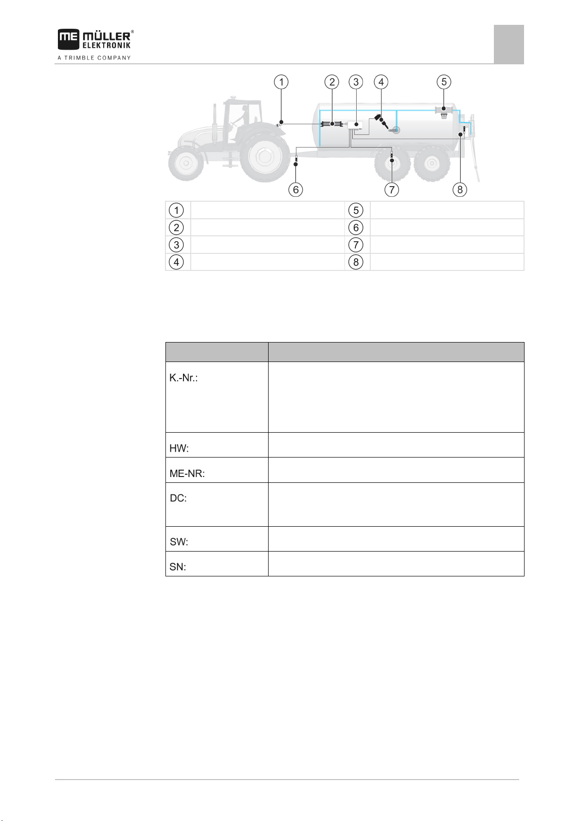
Example
The following diagram shows an example of how an implement can be structured:
Page 11
30322453-02-EN
V4.20191001
11
Abbreviation
Meaning
will be shown here.
Hardware version
Müller-Elektronik item number
The product may only be connected to voltages within this range.
Software version upon delivery
Serial number
2.3
About the job computer
Rating plate
2
ISOBUS power socket
ISOBUS job computer
Junction box
Linear actuator
Flow meter
Rotational speed sensor
Speed sensor
Work position sensor
Rating plate
Abbreviations on the rating plate
Customer number
If the product was manufactured for an agricultural machinery
manufacturer, the agricultural machinery manufacturer's item number
Operating voltage
Page 12

12
V4.20191001
30322453-02-EN
Type of depiction
Meaning
2.
⇨
This will happen when you perform an action.
⇨
steps.
can be performed.
3
3.1
3.2
3.3
3.4
About these Operating Instructions
3
Who is the target user for these Operating Instructions?
About these Operating Instructions
Who is the target user for these Operating Instructions?
These Operating Instructions are intended for operators of slurry tankers equipped with a job
computer from Müller-Elektronik.
Directional information in these instructions
All directional information in these instructions, such as “left”, “right”, “forward”, “back”, is relative to
the movement direction of the vehicle.
Layout of operating instructions
The operating instructions explain step by step how you can perform certain operations with the
product.
We use the following symbols throughout these Operating Instructions to identify different operating
instructions:
1.
Actions that must be performed in succession.
Result of the action.
Result of an operating instruction.
This will happen when you have completed all
Requirements.
In the event that any requirements have been
specified, these must be met before an action
Layout of references
If any references are given in these Operating Instructions, they appear as:
Example of a reference: [➙ 12]
References can be identified by their square brackets and an arrow. The number following the arrow
shows you on what page the section starts where you can find further information.
Page 13

30322453-02-EN
V4.20191001
13
4
4.1
4.1.1
4.1.2
Procedure
4.1.3
Procedure
Mounting and installation
Mounting and installation
Installing the job computer
4
Installing the job computer
Selecting the installation site
Take note of the following when selecting the installation location:
The job computer must be installed on the slurry tanker, not on the tractor.
▪ The job computer should be installed where it is protected from dust and water.
▪ To avoid damage due to the penetration of water, the connections on the job computer must be
pointing to the sides.
Connecting the AMP connectors
This is how to connect two AMP connectors:
1. Pull out the red locking device of the AMP socket all the way to the end.
⇨ You will hear a loud clicking sound.
⇨ The openings for inserting the locking pins of the connector are visible.
2. Insert the connector into the socket. It should be possible to easily insert the locking pins in the
openings.
⇨ The connector is loosely inserted in the socket.
3. Press in the red locking device.
⇨ You will hear a loud clicking sound.
⇨ A part of the locking device comes through to the other side of the socket.
⇨ You have connected and locked the connector with the socket.
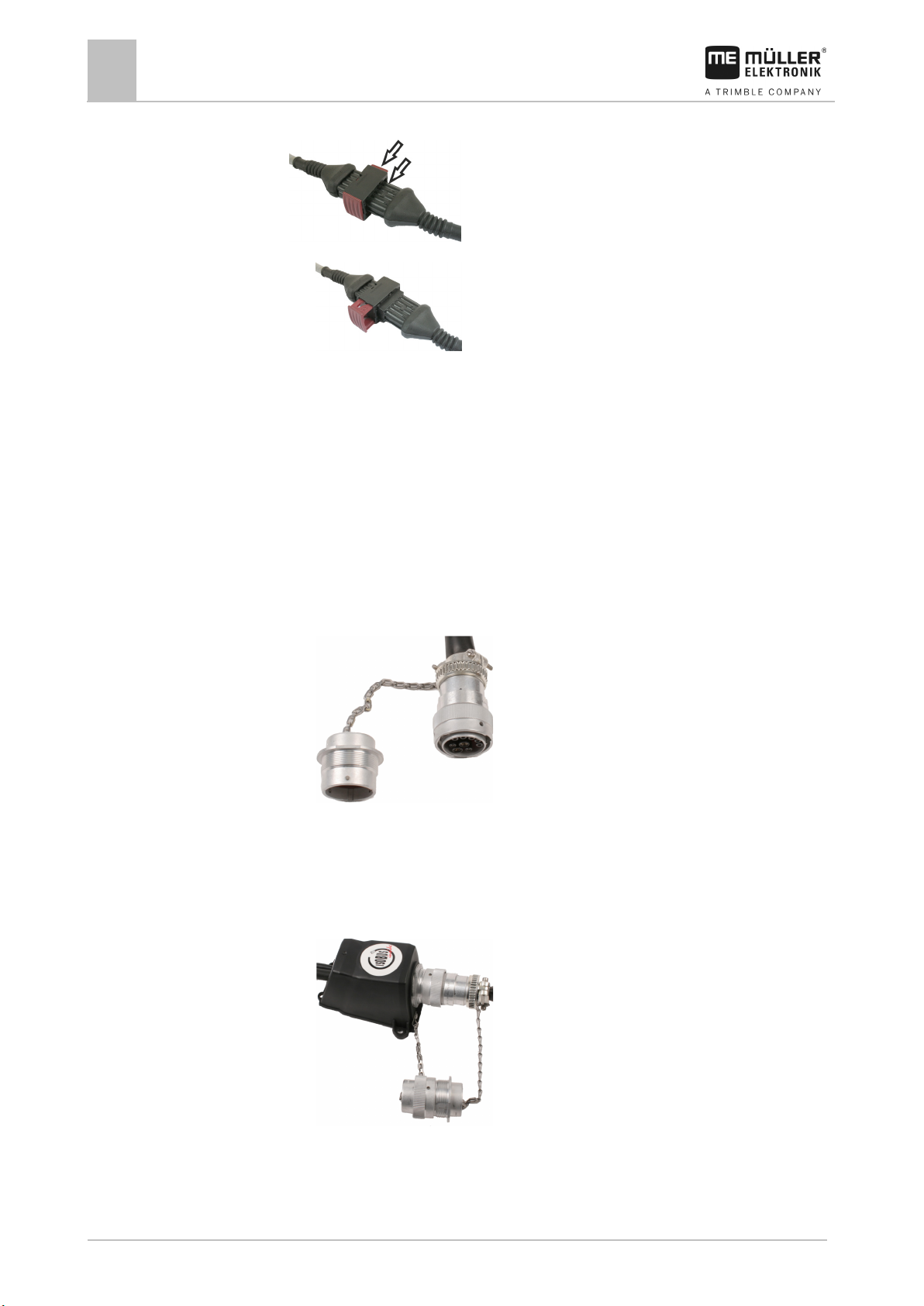
Separating the AMP connectors
This is how to separate two AMP connectors:
Page 14
14
V4.20191001
30322453-02-EN
4.2
Procedure
Mounting and installation
4
Connecting the job computer to the ISOBUS
1. Press in both ends of the red locking device in direction of the connector.
⇨ You will hear a loud clicking sound.
⇨ The locking device has been released.
2. Pull out the red locking device of the AMP socket all the way to the end.
3. Pull the connector out of the socket.
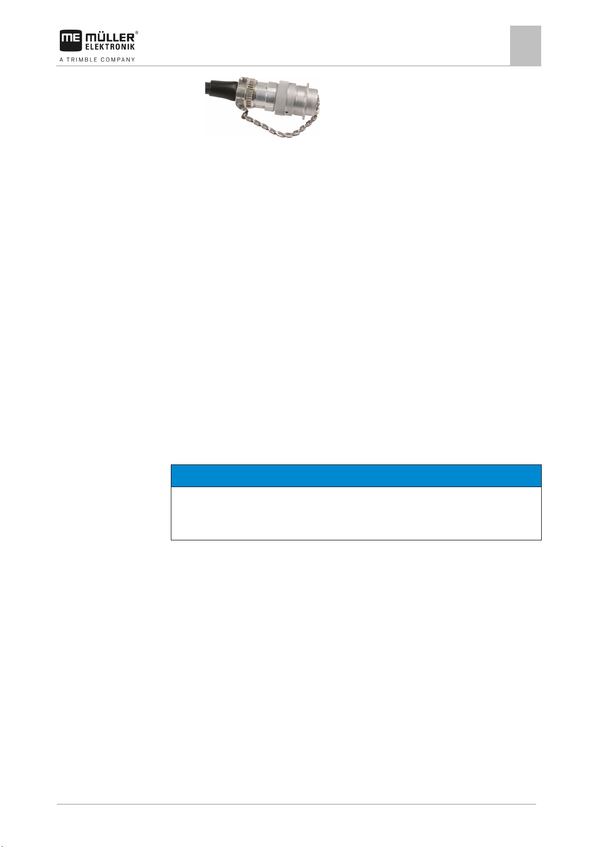
Connecting the job computer to the ISOBUS
To connect the job computer to the power supply and to the ISOBUS terminal, you have to connect
the ISOBUS cable to an ISOBUS power socket on the tractor.
This is how to connect the job computer to the ISOBUS:
1. Take the ISOBUS cable from the job computer.
2. Unscrew the dust protection cap.
⇨
3. Insert the ISOBUS connector into the ISOBUS power socket on the tractor.
4. Lock the connector. For basic vehicle harnesses from Müller-Elektronik, turn the connector
clockwise. For other ISOBUS basic vehicle harnesses, the procedure depends on the model.
⇨ The connector fits tightly.
5. Screw the dust protection cap of the connector and the socket together.
⇨
6. When the work is completed, separate the connection and screw the dust protection cap back
on.
Page 15
30322453-02-EN
V4.20191001
15
NOTICE
Risk of short-circuit
◦ Pay attention to the polarity of the cable cores and the terminals.
4.3
4.3.1
Procedure
Mounting and installation
Installing the junction box
4
⇨
Installing the junction box
Take note of the following when selecting the installation location:
▪ Ensure that cables cannot be damaged by the moving implement.
▪ The cable glands must be facing downwards.
Connecting the sensors and actuators to the junction box
Every sensor and every actuator that is mentioned in the pin-out diagram must be connected to the
connection in the junction box mentioned in the pin-out diagram.
This can be done in two ways:
▪ The sensor or actuator ends with a short cable and an AMP connector.
In this case, you will receive a fitting extension cable for each sensor. You must insert the
extension cable in the junction box and connect it to the fitting terminal.
▪ The sensor or actuator ends with a long cable without a connector. You have to insert it in the
junction box and connect it to the fitting terminal.
The terminal to which you must connect the cable core depends on the respective implement and on
the type of sensor or actuator.
Please note that the cable cores for the ultrasonic sensor trigger always need to be connected to Pins
2 and 3.
When exchanging the polarity of cable cores, machine sensors can be damaged by a short-circuit.
The junction box is not powered.
There is no voltage on the components to be connected.
1. Remove the cable coating so that all cable cores are exposed.
2. Insert the cable to the end of the coat. There should only be cable cores inside the junction box.
The cable coating must end at the junction box casing. This is the only way to ensure that you
have enough space in the junction box to be able to guide all of the cable cores to the terminals.
3. Remove the cable coating of the cable cores ca. 1 cm from the end of the cable core.
4. CAUTION! Pay attention to the proper polarity of the cable cores and the terminals.
5. Connect the cable cores to the terminals.
To do so, use the information on the lid of the junction box, on the relay circuit board and in the
pin-out diagram.
6. With screw terminals, use wire end sleeves. Wire end sleeves may not be used with spring-
loaded terminal blocks.
Page 16

16
V4.20191001
30322453-02-EN
mode)
Rotational speed sensor
Inductive sensor
Position sensor (e.g. working position)
Pressure sensor
Digital pressure sensor
Flow meter
Magnetic inductive liquid flow meter
4.3.2
Procedure
4.3.3
Procedure
4.4
Mounting and installation
4
Installing sensors on the slurry tanker
7. Close the screw connections of the junction box.
After screwing them shut, the glands should be sealed.
8. Close unused openings in the casing of the junction box with blind caps.
Inserting the cable core into a terminal
Each terminal consists of two openings:
▪ The upper opening of the terminal opens the lower opening.
▪ The bottom opening of the terminal serves to insert and clamp one cable core.
You have prepared a small flat screwdriver that fits the upper opening of the terminal. You only
need this screwdriver if there are no wire end sleeves on the cable cores.
You have cut the cable to the proper length and have exposed the cable cores according to the
instructions, or you have a finished cable from Müller Elektronik.
The tractor engine is switched off.
The junction box is not powered.
There is no voltage on the components to be connected.
1. Find the proper connectors for the cable cores to be connected.
To do so, use the information on the lid of the junction box, on the relay circuit board and in the
pin-out diagram.
2. Insert the cable core into the opening in the lower part of the terminal. If you are not using wire
end sleeves, you first have to use the screwdriver.
⇨ The cable core will be held by the terminal.
⇨ You have clamped the cable core.
Connecting the junction box to the job computer
1. Connect the AMP connector of the junction box onto the proper job computer.
Installing sensors on the slurry tanker
The following sensors can be installed on the slurry tanker:
Purpose Sensor type (according to the operating
Speed sensor
Reed contact sensor
Page 17
30322453-02-EN
V4.20191001
17
Pin
Cable color
Designation
1
blue
0 VE
2
brown
12 VE
3
black
Signal
4.4.1
4.4.2
Mounting and installation
Installing sensors on the slurry tanker
4
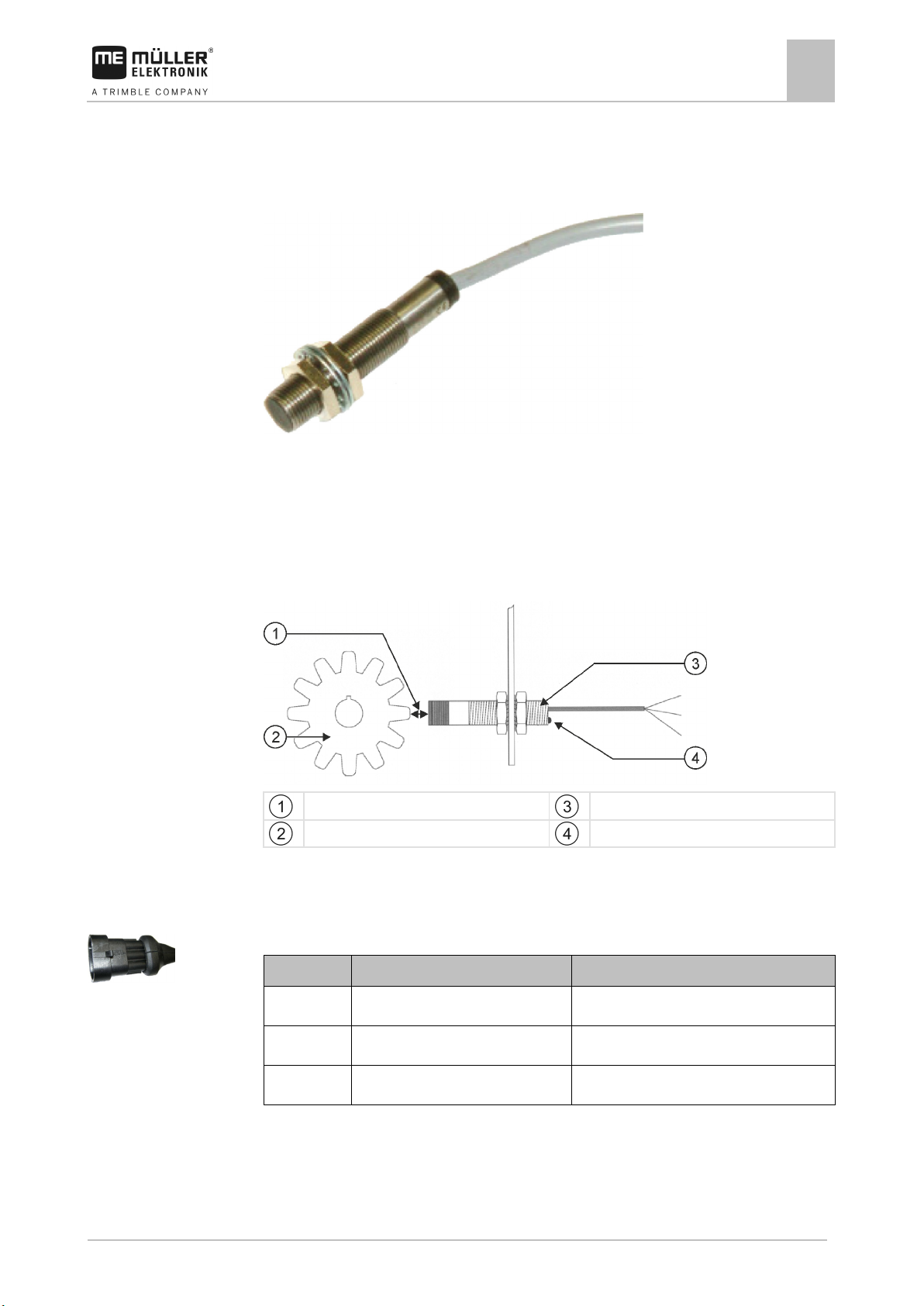
Installing the rotational speed sensors
Inductive sensors are suitable as rotational speed sensors.
Functional principle
A signal is measured when the magnet field of the sensor is influenced by an object made of
magnetically conductive metal. Stainless steel is not suitable for this.
Schematic overview
Reacting distance (depends on the sensor)
Metal object (e.g. gearwheel)
Sensor
Control LED
Connector pin assignment
3-pin AMP connector
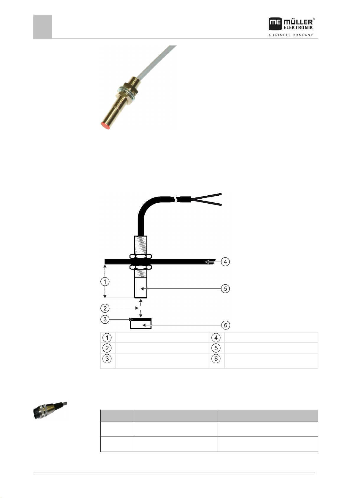
Installing the speed and position sensors
Reed contact sensors are suitable as speed and position sensors.
Page 18
18
V4.20191001
30322453-02-EN
South pole of the magnet (red side)
Magnet (nonmagnetic attachment, e.g. V2A,
copper, brass)
Pin
Cable color
Designation
1
green
Signal
2
brown
Mounting and installation
4
Installing sensors on the slurry tanker
Functional principle
A signal is sent when the red side of a magnet is held in front of the red cap of the sensor. This
creates a connection between the signal line and the ground wire of the sensor.
Schematic overview
Min. 25 mm
Distance 15-25mm
Attachment angle
Sensor (red cap)
Connector pin assignment
3-pin connector
Page 19
30322453-02-EN
V4.20191001
19
Pin
Cable color
Designation
3
white
0 VE
Pin
Cable color
Designation
1
white
0 VE
2
brown
12 VE
3
green
Signal
Pin
Cable color
Designation
1
white
0 VE
2
brown
12 VE
4.4.3
Mounting and installation
3-pin AMP connector
Installing sensors on the slurry tanker
4
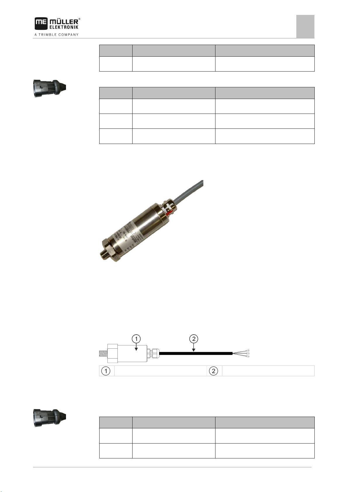
Installing the pressure sensors
Digital pressure sensors with frequency output are suitable as pressure sensors.
Functional principle
A membrane records the pressure. The internal electronics analyse the pressure. The electronics
then send a ground-switching square frequency as an output signal. This output frequency is
proportional to the pressure.
Schematic overview
Pressure sensor
Connector cable
Connector pin assignment
3-pin AMP connector
Page 20
20
V4.20191001
30322453-02-EN
Pin
Cable color
Designation
3
green
Signal
4.4.4
Mounting and installation
4
Installing sensors on the slurry tanker
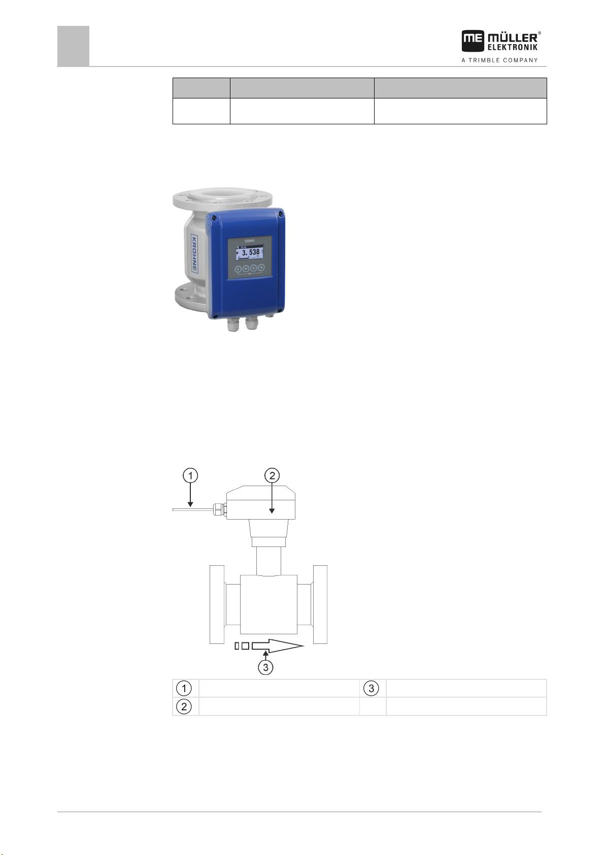
Installing the flow meter
Magnetic inductive liquid flow meters are suitable as a flow meter.
Flange design – type: Krohne
Functional principle
An electrically conductive liquid flows through a magnetic field in an electrically insulated pipe. The
magnetic field is generated by a current flowing through a pair of field coils. A voltage is generated in
the liquid, which can be measured by the sensor.
Schematic overview
Connector cable
Measuring transducer
Flow direction
Page 21
30322453-02-EN
V4.20191001
21
Cable
Designation
1
0VE
2
Signal
3
12 VE
4
0VE
5 (green-yellow)
Ground
Purpose
Actuator (according to the operating mode)
Flow regulation
Linear actuator
4.5
4.5.1
Mounting and installation
Installing actuators on the slurry tanker
4
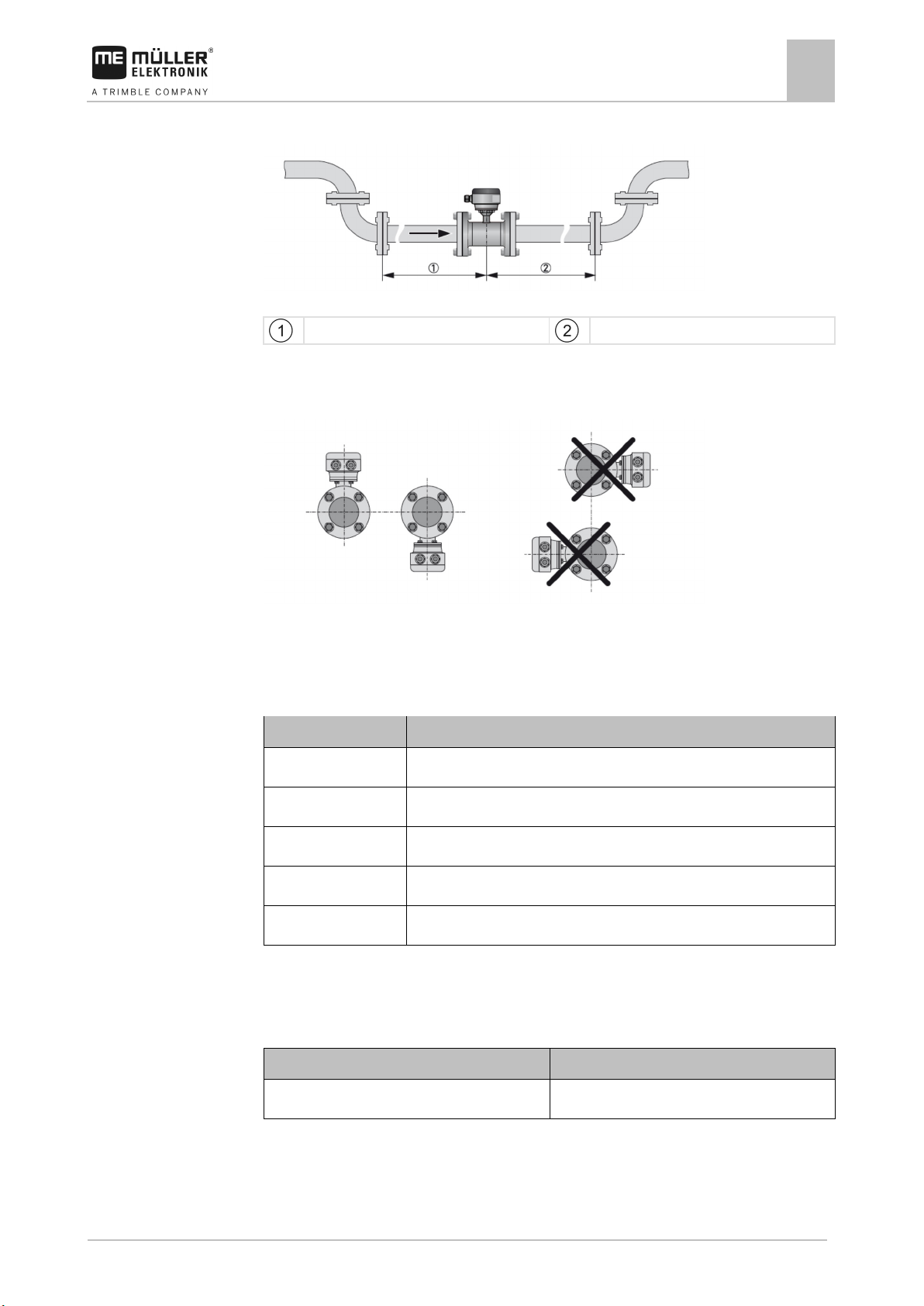
Inlet und outlet
Recommended inlet and outlet
≥ 5 DN
≥ 2 DN
Mounting position
Recommended mounting position
During installation, also observe all the information in the flow meter manual.
Assignment
Installing actuators on the slurry tanker
The following actuators can be installed on the slurry tanker:
Installing linear actuators
Linear actuators are suitable for flow control.
Page 22

22
V4.20191001
30322453-02-EN
Mounting and installation
4
Installing actuators on the slurry tanker
Functional principle
The height of the shutter determines the size of the opening through which the material flows.
Schematic overview
Stroke length: max. 200mm
Assignment
The direction of rotation of the linear actuator is influenced depending on the connection of the
actuator (positive pole or negative pole). The linear actuator rotates in either one or the other
direction.
Page 23

30322453-02-EN
V4.20191001
23
Information on the speed, application rate and fill level
Information on the statuses, activated functions, etc.
Information on the pressure, flow rate, pump speed, activated functions, etc.
5
5.1
Procedure
5.2
Basic control principles
Basic control principles
Switching on the job computer
5
Switching on the job computer
1. Connect the ISOBUS cable of the job computer to the ISOBUS connector on the tractor.
2. Start the ISOBUS terminal.
⇨ The job computer is started together with the terminal.
⇨ When starting up for the first time, the job computer initially has to transmit lots of
information to the terminal. This can take a few minutes.
⇨ When all of the data from the job computer application has been loaded, their icon appears
on the terminal:
.
3. Open the job computer application. To do so, follow the instruction for the ISOBUS terminal.
⇨ The work screen of the job computer appears.
Layout of work screen
The work screen is the first screen that appears when the application is opened. During operation,
the work screen always appears in the foreground and contains the most important information on the
work and the status of the slurry tanker.
The work screen is divided into 3 areas.
Area 1
Area 2
Area 3
The information and number of icons in each area depends on the equipment and activated functions
of the slurry tanker.
Area 1
▪ - The current application rate.
Page 24

24
V4.20191001
30322453-02-EN
Function icon
Meaning
Controls
5.3
Basic control principles
5
Navigation in the software
▪ - The current target rate. If you adjust the target rate during operation [
➙ 28], you will see the adjustment
.
▪
▪
- The current speed of the slurry tanker.
- The current tank content.
In addition, the icon shows the current mode of the slurry tanker.
▪
▪
▪
▪
▪
▪
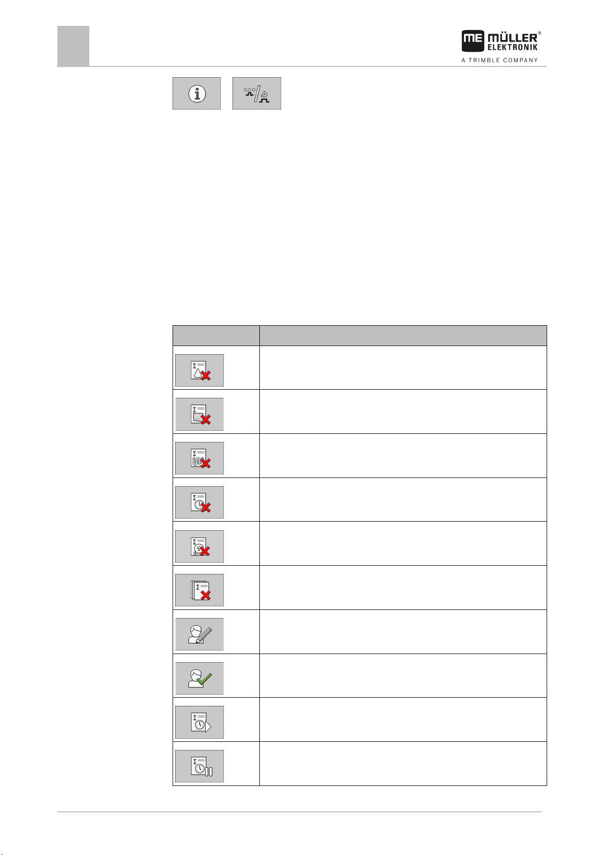
- The slurry tanker is working with a defined target rate.
- The slurry tanker is working without a defined target rate.
- The slurry tanker is working without pre-set sequences.
- The slurry tanker is currently performing the application.
- The slurry tanker is not currently performing the application.
- The tank is activated, but the slurry tanker is currently not spreading because
SECTION-Control is deactivated.
▪
- Sections are switched via SECTION-Control.
and then the new target rate
▪
- The SECTION-Control application has closed all sections.
Area 2
Overviews of the individual icons that may appear in Area 2 can be found in the sections on the
Operation and Configuration [➙ 44] of the slurry tanker.
Area 3
▪ - The current flow rate.
Use the following function keys to operate the function:
Show the information from Area 3.
Hide the information from Area 3.
Navigation in the software
Depending on the equipment of the slurry tanker and the scope of its functions, it is possible that not
all of the executable functions are shown on one page of the screen.
Page 25

30322453-02-EN
V4.20191001
25
Function icon
Meaning
Pressed long: Scrolls back to the previous screen.
Controls
Basic control principles
Navigation in the software
5
If there are other functions that can be executed, one of the following function buttons always
appears:
Use the following function keys to operate the function:
Scrolls between several pages.
Scrolls back to the previous screen.
Pressed briefly: Scrolls to the next page.
In this manual, if one of the function buttons is shown in parentheses, e.g. “( )”, it means
that the function button must not be pressed or must be pressed several times, depending on the
configuration.
This manual always shows the standard path to reach the individual functions. The layout of the
function buttons can also be rearranged in the configuration of the job computer. In this case, the
path differs.
Page 26

26
V4.20191001
30322453-02-EN
6
6.1
6.1.1
Procedure
6.1.2
Path
Operating job computer on the field
6
Controlling the application
Operating job computer on the field
Controlling the application
Setting target rate
Use the following parameter on the “SETTINGS” screen to define how much slurry should be applied
on an area.
▪ “Target Rate”
Defines how much slurry should be applied per hectare.
▪ “Unit”
Defines the unit that should be used for the metering, depending on whether you want to
measure the volume or the mass.
– “Regul. (Vol.)”
– “Regul. (Mass)”
– “Reg. Phosphorus”
– “Reg. Nitrogen”
– “Reg. Ammonia”
– “Reg. Pottasium”
▪ “Density”
Defines the density of the slurry.
▪ “Regul. factor”
Defines the adjustment of the flow rate for the speed. This should ensure that the applied volume
of slurry corresponds exactly to the defined target rate.
The regulation factor adjusts the reaction speed of the regulation:
– The higher the regulation factor, the faster the flow rate is adjusted.
– The lower the regulation factor, the more slowly the flow rate is adjusted.
When setting the regulation factor, you can pay attention to the following:
– If, during movement at constant speed, the current application rate jumps around the target
rate, you need to reduce the regulation factor.
– If, when the speed changes, the application rate does not adjust to the target rate quickly
enough, you need to increase the regulation factor.
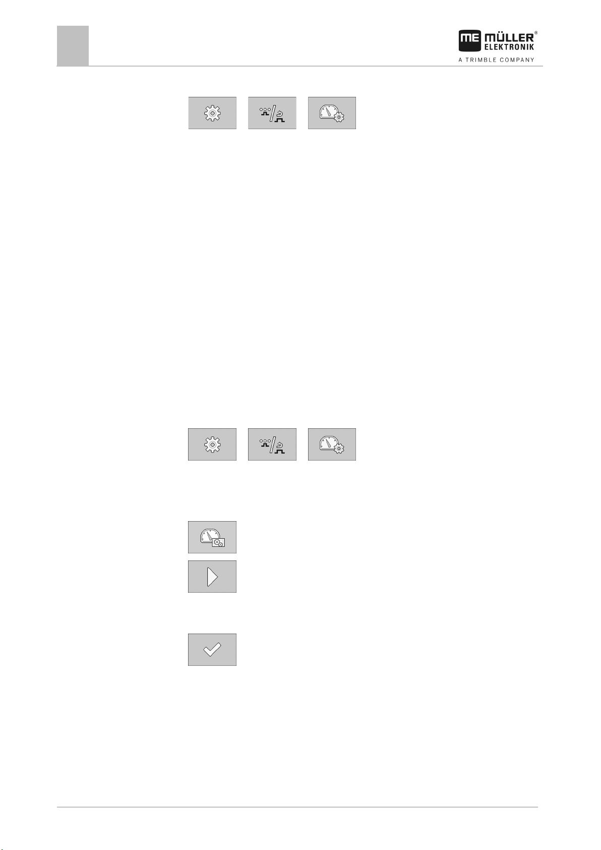
1. On the work screen, press:
⇨ The “SETTINGS” screen appears.
2. Configure the parameters.
Starting and stopping the application
This is how you reach the screen with this function:
Page 27

30322453-02-EN
V4.20191001
27
Procedure
Procedure
Operating job computer on the field
Controlling the application
6
> ( )
You have 2 options for starting and stopping the application:
▪ Using a configured sequence
A sequence defines which function of the slurry tanker is performed for how long when you start
or stop the application.
▪ Manual
You must manually activate all functions of the slurry tanker when you start or stop the
application.
Application using a pre-set sequence
A sequence is configured.
1.
⇨ The following icon may not appear in Area 1:
2.
⇨ You can see the current status by the icons:
- Ensure that you are not in manual application mode.
- Start application.
for Application started and for
Application stopped.
3. Apply the slurry.
4.
Manual application
- Stop the application after finishing work.
1. - Activate the manual application mode.
⇨ The following icon appears in Area 1:
2.
- Start application.
⇨ You can see the current status by the icons:
for Application started and for
Application stopped.
3. Activate the desired functions successively. You can see the possible functions at the end of this
section.
4. Apply the slurry.
5.
- Stop the application after finishing work.
6. Deactivate the desired functions successively. The following functions are possible:
▪ Opening and closing the application valve [➙ 28]
Page 28
28
V4.20191001
30322453-02-EN
Function icon
Meaning
Icon
Meaning
Function icon
Meaning
6.1.3
Path
Controls
Icons
6.1.4
Path
Controls
Operating job computer on the field
6
Controlling the application
▪ Adjusting the target rate during operation [➙ 28]
▪ Operating section valves [➙ 29]
▪ Spreading the slurry evenly across the working width [➙ 30]
▪ Operating the drop stop [➙ 31]
Opening and closing the application valve
You can open and close the application valve to start or stop the application.
This is how you reach the screen with this function:
(
Use the following function keys to operate the function:
)
Opens the application valve.
Closes the application valve.
The following icons may appear on the work screen:
The application valve is open.
The application valve is closed.
Adjusting the target rate during operation
You can amend the target rate while working.
This is how you reach the screen with this function:
> ( )
Use the following function keys to operate the function:
Restores the target rate back to 100%.
Stops or starts the application.
Page 29

30322453-02-EN
V4.20191001
29
Function icon
Meaning
▪ Manual: You are working without a pre-set target rate.
Function icon
Meaning
Procedure
6.1.5
Path
Controls
Operating job computer on the field
Controlling the application
6
Reduces the target rate by 10%.
Increases the target rate by 10%.
Switches between automatic and manual target rate regulation.
▪ Automatic: The entered target rate from the “Target Rate” parameter is
used. [➙ 26]
Switches between automatic and manual sequence.
1. - Switch to automatic target rate control.
⇨ The following icon appears in Area 1:
2.
, or - Change the target rate.
⇨ In Area 1, the change and then the new target rate is shown:
→ →
⇨ The job computer regulates the application according to the new target rate.
Operating section valves
This is how you reach the screen with this function:
Use the following function keys to operate the function:
> ( )
Opens all of the section valves of the first section group.
Opens all of the section valves of the second section group.
Closes all of the section valves on the outer left side.
Page 30

30
V4.20191001
30322453-02-EN
Function icon
Meaning
Function icon
Meaning
rotation also changes.
Icon
Meaning
Procedure
6.1.6
Path
Controls
Icons
Operating job computer on the field
6
Controlling the application
Closes all of the section valves on the inner left side.
You have configured the sections. [➙ 49]
1. Press the function button with the desired function.
⇨ The selected section valves will be opened or closed.
⇨ The change is shown on the work screen, e.g. opening of the right section valves:
→
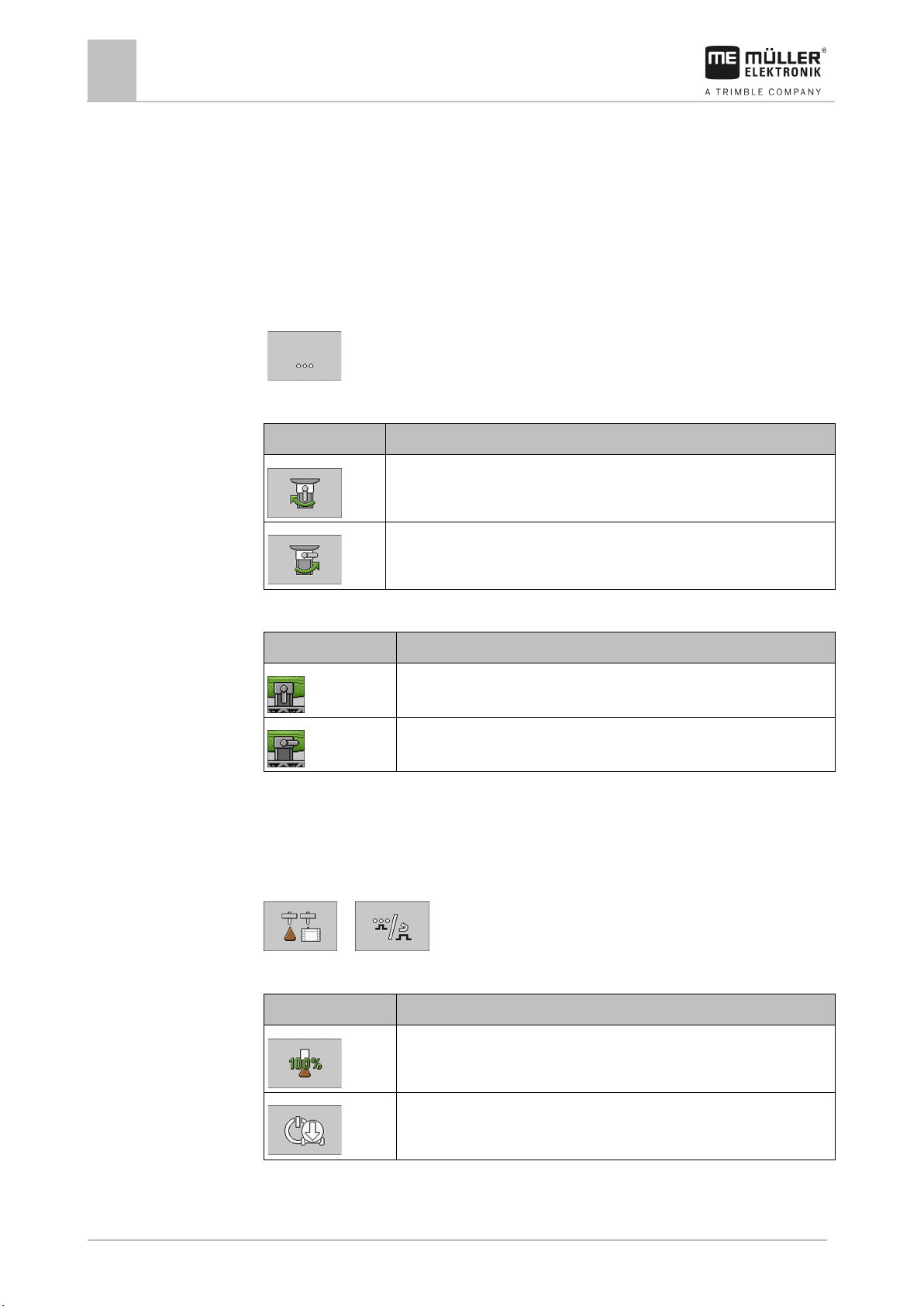
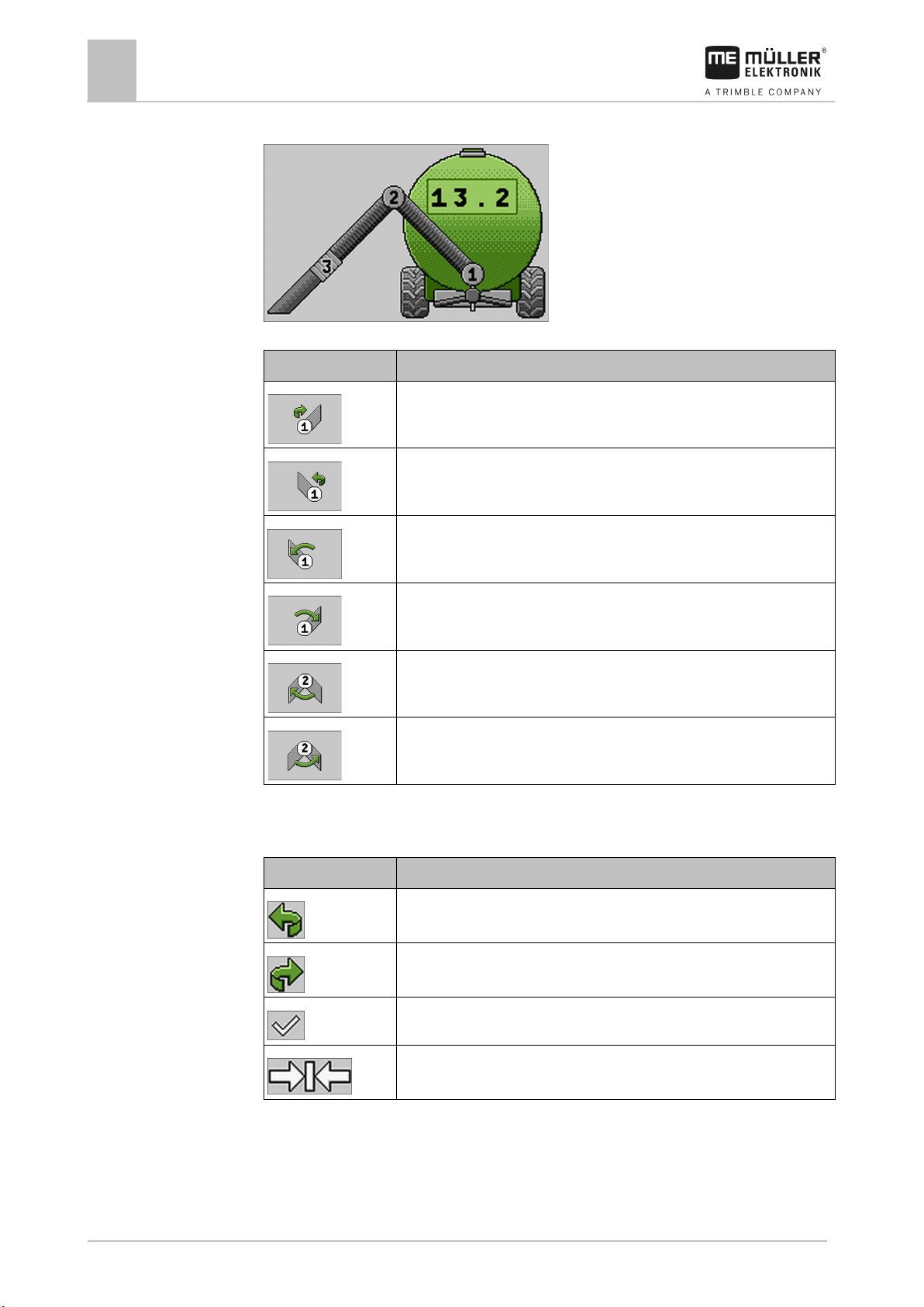
Spreading the slurry evenly across the working width
If the slurry tanker is equipped with a divider, you can spread the slurry evenly across the working
width.
This is how you reach the screen with this function:
(
)
Use the following function keys to operate the function:
Switches between automatic and manual mode. If you are using two
dividers, both dividers are always switched simultaneously.
In manual mode: Starts and stops the divider.
In automatic mode: Depending on how often it is pressed, the direction of
The following icons may appear on the work screen:
The divider is in automatic mode, but it is not activated.
The divider is in automatic mode and rotates to the left.
The divider is in automatic mode and rotates to the right.
The divider is in manual mode and rotates to the left, when it is activated.
Page 31

30322453-02-EN
V4.20191001
31
Icon
Meaning
Function icon
Meaning
6.1.7
Path
Controls
Icons
Operating job computer on the field
Controlling the application
6
The divider is in manual mode and rotates to the right, when it is activated.
The divider is in manual mode and rotates to the left.
The divider is in manual mode and rotates to the right.
Operating the drop stop
The drop stop prevents excess slurry from dripping out of the mounted implement after finishing work.
Depending on the mounted implement, a different drop stop may be installed.
This is how you reach the screen with this function:
(
)
Use the following function keys to operate the function:
Depending on the mounted implement, the function buttons may differ.
Mounted implement without boom
Activates the drop stop.
Deactivates the drop stop.
Activates the left drop stop.
Deactivates the left drop stop.
Activates the right drop stop.
Deactivates the right drop stop.
The following icons may appear on the work screen:
Page 32

32
V4.20191001
30322453-02-EN
Icon
Meaning
6.2
Path
Procedure
Operating job computer on the field
6
Filling the slurry tanker
Mounted implement without boom
Left drop stop is activated.
Right drop stop is activated.
Left drop stop is deactivated.
Right drop stop is deactivated.
Left drop stop is being activated.
Right drop stop is being activated.
Left drop stop is being deactivated.
Right drop stop is being deactivated.
Filling the slurry tanker
This is how you reach the screen with this function:
> ( )
You have 2 options for filling the slurry tanker:
▪ Using a configured sequence
A sequence defines which functions of the slurry tanker are performed during the filling
procedure and for how long.
▪ Manual
You must manually activate all of the functions for filling the slurry tanker.
Filling using a sequence
A sequence is configured.
1.
- Ensure that you are not in manual filling mode.
⇨ The following icon may not appear in Area 1:
2. Select a filling mode.
3.
- Start filling.
Page 33
30322453-02-EN
V4.20191001
33
Procedure
6.2.1
Path
Controls
Operating job computer on the field
Filling the slurry tanker
6
⇨ You can see the current status by the icons: for Filling started and for Filling
stopped.
⇨ All of the pre-set functions are activated successively.
4.
- Stop filling after the end of the sequence.
⇨ You have filled the tank using a pre-set sequence.
1.
Manual filling
- Optionally, you can now set the tank content manually to the maximum level.
1. - Activate the manual filling mode.
⇨ The following icon appears in Area 1:
2. Select a filling mode.
3.
⇨ You can see the current status by the icons:
- Start filling.
for Filling started and for Filling
stopped.
4. Depending on the equipment of the slurry tanker, perform the following functions:
▪ Moving the filling arms [➙ 33]
▪ Using a folding sequence for filling arms
▪ Opening and closing the valves [➙ 34]
▪ Increasing the filling speed [➙ 35]
▪ Chopping up foreign objects in the slurry [➙ 36]
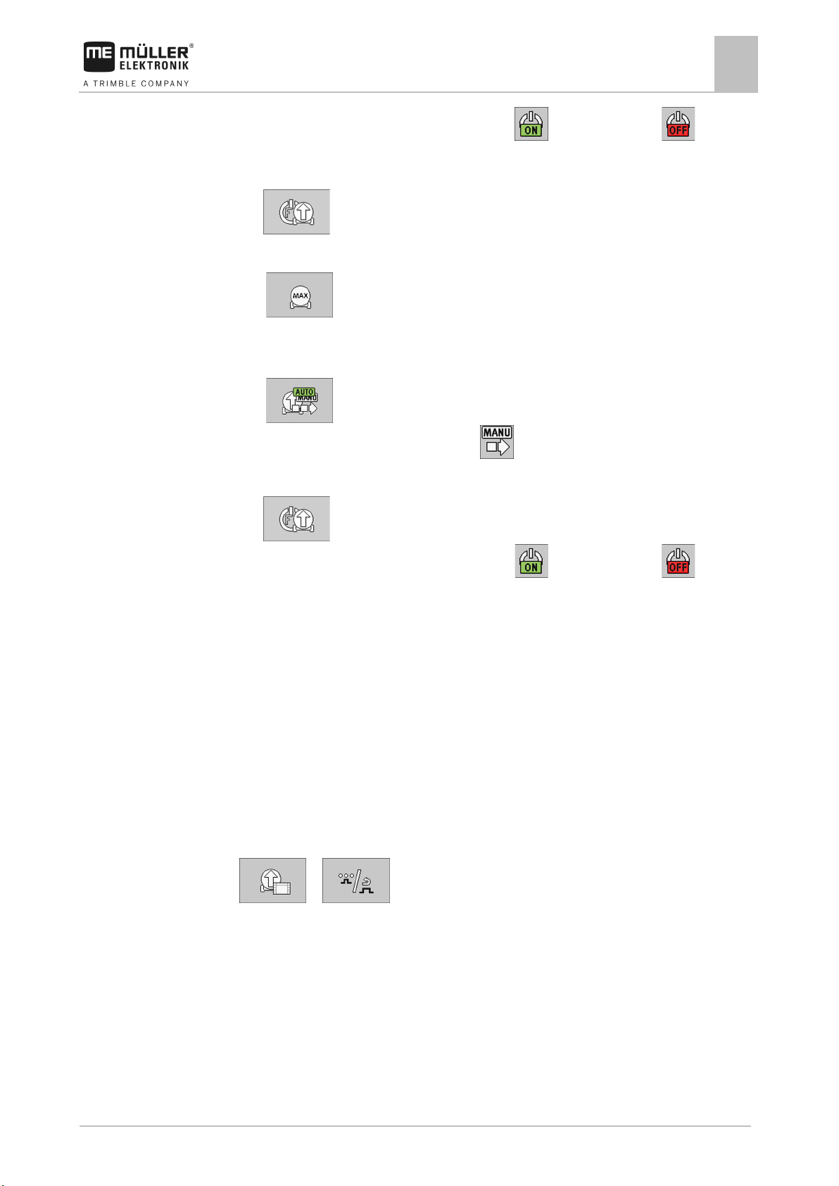
Moving the filling arms
All of the filling arms on the slurry tanker can be moved. You can lift or lower the individual parts of
the filling arm for the filling procedure.
This is how you reach the screen with this function:
> ( )
The function buttons differ depending on which filling arm you are using. On the screen, you can see
a diagram with the respective moving parts of the filling arm.
Use the following function keys to operate the function:
Page 34
34
V4.20191001
30322453-02-EN
Function icon
Meaning
Icon
Meaning
Icons
6.2.2
Path
Operating job computer on the field
6
Filling the slurry tanker
Front filling arm
Example: Front filling arm with 3 moving parts
Turns the front filling arm to the right.
Turns the front filling arm to the left.
Lowers the first part of the front filling arm to the left.
Lowers the first part of the front filling arm to the right.
Lifts the second part of the front filling arm to the left.
Lifts the second part of the front filling arm to the right.
The icons are always on the respective moving parts of the filling arm.
The following icons may appear on the work screen:
Moving part of the filling arm is turned to the left.
Moving part of the filling arm is turned to the right.
Moving part of the filling arm has reached the end position.
Moving part of the filling arm is centered.
Opening and closing the valves
This is how you reach the screen with this function:
Page 35

30322453-02-EN
V4.20191001
35
Function icon
Meaning
Icon
Meaning
Function icon
Meaning
Controls
Icons
6.2.3
Path
Controls
Icons
Operating job computer on the field
Filling the slurry tanker
6
Use the following function keys to operate the function:
> ( )
Opens the valve.
Closes the valve.
The following icons may appear on the work screen:
The valve is being opened.
The valve is being closed.
The valve is open.
The valve is closed.
Increasing the filling speed
You can increase the filling speed of the tank if you are using a filling turbo.
This is how you reach the screen with this function:
> ( )
Use the following function keys to operate the function:
Starts the filling turbo.
Stops the filling turbo.
Changes the direction of rotation of the filling turbo.
The following icons may appear on the work screen:
Page 36

36
V4.20191001
30322453-02-EN
Icon
Meaning
Function icon
Meaning
Icon
Meaning
6.2.4
Path
Controls
Icons
6.3
6.3.1
Path
Operating job computer on the field
6
Operating the mounted implement
Filling Turbo is deactivated.
Filling Turbo is activated.
Chopping up foreign objects in the slurry
You can chop up foreign objects in the slurry to achieve better flow.
This is how you reach the screen with this function:
Use the following function keys to operate the function:
> ( )
Starts and stops the chopper.
Switches the chopper from automatic to manual mode and vice versa.
The following icons may appear on the work screen:
Chopper rotates to the left.
Chopper rotates to the right.
Chopper rotates to the left and has detected a problem.
Chopper rotates to the right and has detected a problem.
Operating the mounted implement
Folding the booms of a mounted implement
If the mounted implement has a boom, you can fold and unfold the boom. You can only start working
when the boom is unfolded.
This is how you reach the screen with this function:
> ( )
Page 37
30322453-02-EN
V4.20191001
37
Arrow pointing outwards means: Fold out
Function icon
Meaning
Controls
Procedure
6.3.2
Path
Controls
Operating job computer on the field
Operating the mounted implement
6
Depending on the size of the boom, different function icons appear.
In the following diagram, you can see what a boom with three sections on each side looks like on a
function icon.
Directional arrow
Arrow pointing inwards means: Fold in
Boom sections marked in grey will not be folded and unfolded with this function icon.
Boom sections marked in white will be folded and unfolded with this function icon.
Use the following function keys to operate the function:
Folds the first section of the boom.
Unfolds the first section of the boom.
1. Press the function button with the desired function.
⇨ The boom will be folded or unfolded.
⇨ Folding or unfolding is shown by an arrow on the work screen, e.g. for unfolding the second
section of the boom:
2. Press and hold the function button until the boom is folded or unfolded.
Adjusting the lower link position
During operation, you can adjust the position of the lower link hydraulically to reach the working
position.
Depending on the mounted implement, the possible functions and icons differ for adjusting the lower
link.
This is how you reach the screen with this function:
> ( )
Use the following function keys to operate the function:
Page 38

38
V4.20191001
30322453-02-EN
Function icon
Meaning
Icon
Meaning
Function icon
Meaning
Icons
6.4
6.4.1
Path
Controls
Operating job computer on the field
6
Adjusting the chassis
Lowers the lower link.
Lifts the lower link.
Puts the lower link into float position.
The following icons may appear on the work screen:
The slurry tanker has a lower link.
Lower link is being lowered.
Lower link is being lifted.
Lower link is in float position.
The lower link is being put in float position.
Adjusting the chassis
You can adjust the chassis to
▪ achieve greater traction,
▪ increase comfort when driving on roads,
▪ change the trailing behaviour,
▪ reduce the ground pressure.
Adjusting the drawbar position
This is how you reach the screen with this function:
> ( )
Use the following function keys to operate the function:
Lowers the drawbar.
Page 39

30322453-02-EN
V4.20191001
39
Function icon
Meaning
Icon
Meaning
Function icon
Meaning
Icon
Meaning
Icons
6.5
Path
Controls
Icons
6.6
Path
Operating job computer on the field
Switching the lighting on and off
6
Lifts the drawbar.
The following icons may appear on the work screen:
Drawbar is being lifted.
Drawbar is being lowered.
Switching the lighting on and off
This is how you reach the screen with this function:
(
Use the following function keys to operate the function:
)
Switches the working lights on and off.
Switches the beacon on and off.
The following icons may appear on the work screen:
Working lights are switched on.
Beacon is switched on.
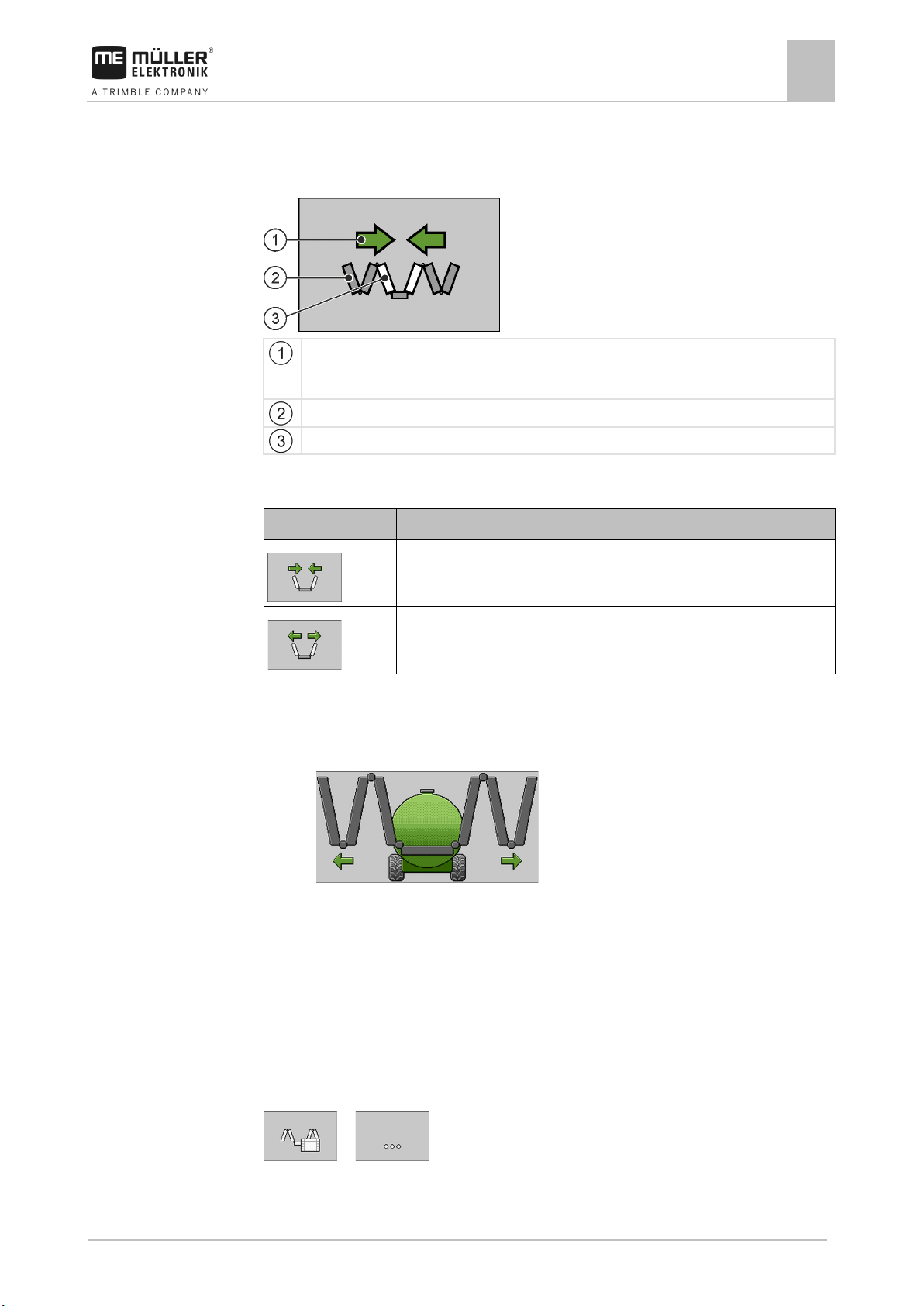
Viewing the assignment of the joystick
You can use the joystick to perform functions of the job computer. Depending on the configuration of
the job computer, the assignment of the individual buttons on the joystick differs. On the screens
where you can perform functions, you can view the assignment of the joystick if you are using a
joystick with AUX-1 protocol.
The procedure for performing a function with the joystick can be found in the operating instructions for
the joystick.
This is how you reach the screen with this function:
Page 40
40
V4.20191001
30322453-02-EN
Function icon
Meaning
Controls
6.7
6.7.1
Path
Controls
Operating job computer on the field
6
Documenting work results
- Appears on various screens.
If you are using a Joystick III from Müller-Elektronik, you can switch between the individual levels in
the software.
Use the following function keys to operate the function:
Shows the assignment of the upper level.
Shows the assignment of the middle level.
Shows the assignment of the bottom level.
Documenting work results
To document the work results, you can view and configure various counters on the “RESULTS”
screen.
The following counters are available:
▪ Trip counter
▪ Customer-specific total counter
▪ Implement counter
Trip counter
The trip counter counts the work results for a customer for the current work.
This is how you reach the screen with this function:
> ( )
The following counters are available:
▪ “Quantity”
Shows the applied quantity for the current day.
▪ “Area”
Shows the applied area for the current day.
▪ “Distance”
Shows the driven distance for the current day.
▪ “Working time”
Shows the duration of the application for the current day.
▪ “Number of tanks”
Shows the number of applied tanks for the current day.
Use the following function keys to operate the function:
Page 41

30322453-02-EN
V4.20191001
41
Function icon
Meaning
Procedure
6.7.2
Path
Operating job computer on the field
Documenting work results
6
Resets the quantity.
Resets the area.
Resets the distance.
Resets the working time.
Resets the number of tanks.
Resets all counters.
Opens the screen for renaming a customer.
Confirms a new selected customer.
Starts the counters.
Stops the counters.
1. Select the customer for whom you want to document the work. If you do not want to assign the
work to a special customer, select “Univ. counter”.
2.
- Confirm. If you do not confirm, the counters from the previously selected
customer will still be shown.
3.
4.
- You have the option of giving the customer a different name.
or - Start or stop the trip counter.
Customer-specific total counter
The customer-specific total counter documents the total work results for a given customer.
This is how you reach the screen with this function:
Page 42
42
V4.20191001
30322453-02-EN
Function icon
Meaning
Controls
Operating job computer on the field
6
Documenting work results
> ( )
The following counters are available:
▪ “Total quantity”
Shows the total applied quantity for the selected customer.
▪ “Total area”
Shows the total applied area for the selected customer.
▪ “Total distance”
Shows the total driven distance for the selected customer.
▪ “Total time”
Shows the total duration of the application for the selected customer.
▪ “Service Hours”
Shows the total time during which the job computer was switched on for the selected customer.
▪ “Total number of tanks”
Shows the total number of tanks that were applied for the selected customer.
Use the following function keys to operate the function:
Resets the quantity.
Resets the area.
Resets the distance.
Resets the working time.
Resets the number of tanks.
Resets all counters.
Opens the screen for renaming a customer.
Confirms a new selected customer.
Starts the counters.
Stops the counters.
Page 43

30322453-02-EN
V4.20191001
43
Procedure
6.7.3
Path
Operating job computer on the field
Documenting work results
6
1. Select the customer for whom you want to document the work. If you do not want to assign the
work to a special customer, select “Univ. counter”.
2.
- Confirm. If you do not confirm, the counters from the previously selected
customer will still be shown.
3.
4.
- You have the option of giving the customer a different name.
or - Start or stop the customer-specific total counter.
Implement counter
The implement counter documents the total work results for an implement.
This is how you reach the screen with this function:
> ( )
The following counters are available:
▪ “Total quantity”
Shows the total applied quantity for the implement.
▪ “Total area”
Shows the total applied area for the implement.
▪ “Total distance”
Shows the total driven distance for the implement.
▪ “Total time”
Shows the total duration of the application for the implement.
▪ “Service Hours”
Shows the total time during which the job computer was switched on.
▪ “Total number of tanks”
Shows the total number of tanks that were applied with the implement until now.
Page 44

44
V4.20191001
30322453-02-EN
7
Procedure
7.1
Procedure
Configuring the job computer for work
7
Entering the geometry
Configuring the job computer for work
Before you start working, you must configure the job computer for the work. You must perform the
configuration of the job computer on the “SETTINGS” screen.
Note that depending on the model of the slurry tanker, not all of the parameters can be configured.
To reach the “SETTINGS” screen:
1. On the work screen, press:
⇨ The “SETTINGS” screen appears.
⇨ You can see parameters and function icons for the configuration.
2. If the desired parameters or function icons cannot be seen directly, press
to scroll
to the next page.
⇨ You can perform the configuration.
Entering the geometry
The geometry of an agricultural implement is defined as a series of parameters describing its
dimensions.
The geometry is important particularly for all systems that are GPS-controlled.
The distances you enter depend on whether the implement is towed, mounted on the tractor or selfpropelled.
1. On the work screen, press:
> ( ) >
⇨ The “GEOMETRY” screen appears.
⇨ On the screen, you can see which measurements need to be taken and where they can be
entered.
2. Enter the measured values. With mounted implements that have a boom that is not straight, but
rather curved towards the front, you must enter the values for the individual sections. With
and
3.
4.
, you can switch between the sections.
- Optionally, you can change the name of the mounted implement.
- Optionally, you can call up the “GEOMETRY / Section-Control” screen.
5. Configure the parameters
⇨ You have configured the geometry.
Page 45

30322453-02-EN
V4.20191001
45
Source
To configure the speed source
receiver or a sensor)
mounted on the implement
46]
Simulated speed
Entering the simulated speed [➙ 46]
7.1.1
7.1.2
7.1.3
7.1.4
7.2
7.2.1
Configuring the job computer for work
Selecting and configuring the speed source
7
“Min. working speed” parameter
Enter the minimum speed at which SECTION-Control should be used. Section control is switched off
below this speed.
“Delay - Sequence” parameter
Enter the delay with which the slurry tanker should work while you are using a sequence for filling or
application.
If the slurry tanker switches too late, increase the delay.
If the slurry tanker switches too early, decrease the delay.
“Delay on start” parameter
Enter the delay when switching the slurry tanker on.
If the slurry tanker switches too late, increase the delay.
If the slurry tanker switches too early, decrease the delay.
“Delay on stop” parameter
Enter the delay when switching the slurry tanker off.
If the slurry tanker switches too late, increase the delay.
If the slurry tanker switches too early, decrease the delay.
Selecting and configuring the speed source
You must enter the source from which the job computer shall obtain the current speed.
The configuration procedure can differ depending on the speed source.
Possible speed sources
Speed signal from the tractor (GPS
Impulse-transmitting speed sensor
Using the speed signal from the tractor [➙ 45]
Calibrating the speed sensor with the 100m method [➙
Using the speed signal from the tractor
Some implements do not have a speed sensor. Instead, the speed signal is transmitted through the
ISOBUS cable from the tractor to the job computer of the implement.
Page 46
46
V4.20191001
30322453-02-EN
Procedure
7.2.2
Procedure
7.2.3
Configuring the job computer for work
7
Selecting and configuring the speed source
1. On the work screen, press:
> ( ) >
⇨ The “SPEED” screen appears.
2. In the “Speed Source” parameter, select the value “Auto”. If the speed on the display fluctuates,
you can also select either the “GPS” or “Gearbox” value as an alternative.
3. In the “Detect Driving Direct.” parameter, select the value “Auto”. If the driving direction on the
display fluctuates, you can also select either the “GPS” or “Gearbox” value as an alternative.
⇨ The speed signal from the tractor will be used.
Calibrating the speed sensor with the 100m method
When calibrating the speed sensor with the 100m method, you determine the number of impulses
received by the speed sensor in a distance of 100m. When you know the amount of impulses, the job
computer can calculate the current speed.
After the first calibration, you can manually enter the number of impulses as the value of the “Wheel
Impulses” parameter.
1. Drive the slurry tanker onto the field.
2. Mark the tyre position on the ground. You can use a stone for instance.
3. Measure a straight route of 100 m and mark the end.
4. On the work screen, press:
> ( ) >
⇨ The “SPEED” screen appears.
5. In the “Speed Source” parameter, select the value “Sensor”.
6. In the “Detect Driving Direct.” parameter, select the value “Sensor”.
7.
8.
- Call up the “CALIBRATION” screen.
- Start the calibration.
9. Drive the marked distance.
⇨ While driving, the counted impulses are shown in the “Counted Impulses” field.
10.
⇨ Calibration will be finished.
- Press when you have reached your destination.
Entering the simulated speed
To test the proper functioning of a sensor, you can simulate a speed.
Page 47
30322453-02-EN
V4.20191001
47
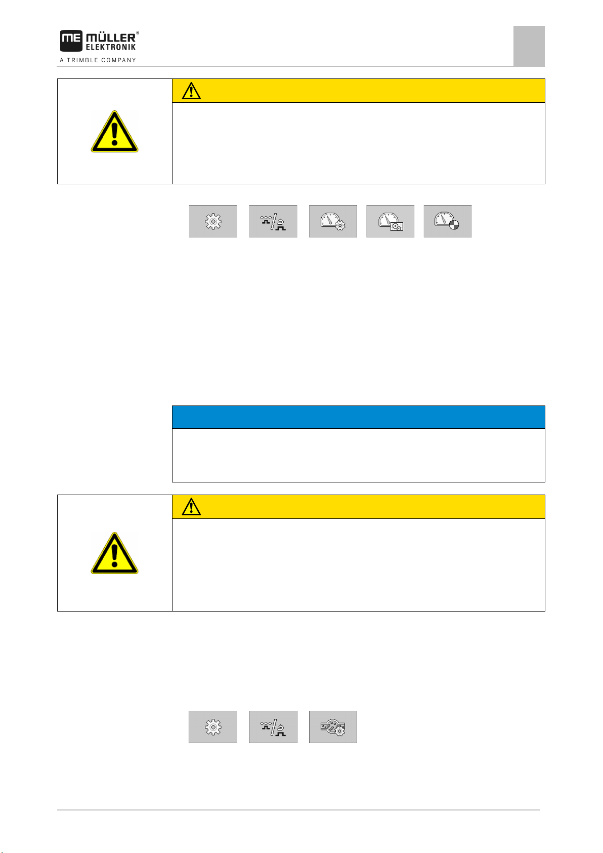
CAUTION
Injury caused by working machine
If the function is activated when the implement is at a standstill, the driver can activate functions that
◦ Make sure that no one is close to the implement.
NOTICE
Imprecise calibration
◦ Calibrate the flow meter very precisely.
CAUTION
Slurry or slurry residues
◦ Wear required protective equipment.
Procedure
7.3
Procedure
Configuring the job computer for work
Calibrating the flow meter
7
can otherwise only be activated during travel. This can cause injury to persons standing close to the
implement.
1. On the work screen, press:
> ( ) > > >
2. In the “Simulated speed” parameter, enter the speed to be simulated.
⇨ The desired speed will be simulated.
Calibrating the flow meter
You must calibrate the flow meter in the following cases:
▪ Prior to initial start-up.
▪ At the start of each season.
▪ If you notice that there are deviations between the applied quantity and the displayed quantity.
▪ After repairs performed on the flow meter.
If the calibration is imprecise, the calculations will be very inaccurate and the application imprecise.
Risk of poisoning or corrosion
◦ Clean the tank before calibration.
◦ Only use clear water for the calibration.
The tank is filled with water. You need several hundred litres of water.
You have a method for measuring the quantity of applied water.
The pump is switched on.
1. Drive the slurry tanker to a position where you can apply the water without any problems.
2. On the work screen, press:
> ( ) >
⇨ The “FLOW METER” screen appears.
Page 48

48
V4.20191001
30322453-02-EN
Function icon
Meaning
7.3.1
7.3.2
7.4
Controls
Procedure
Configuring the job computer for work
7
Configuring the fill level sensor
3. - Call up the “CALIBRATION” screen.
4.
- Start the calibration.
5. Apply several hundred litres of water.
⇨ While applying, the counted impulses are shown in the “Counted Impulses” field.
6.
- Stop the calibration.
7. Enter the quantity of the applied water in the “Quantity” field.
⇨ You have successfully calibrated the flow meter.
8. As an option, you can configure the “Correction Factor” and “Flow Meter Impulses”
parameters.
“Correction Factor” parameter
Enter a factor with which the current tank content should be multiplied.
Only use this parameter if the displayed tank content does not correspond to the actual tank content.
The standard set value is “1.000”.
“Flow Meter Impulses” parameter
Enter the number of impulses for the flow meter manually if you have already previously calibrated
the flow meter.
Configuring the fill level sensor
If you are working with fill level sensors, they must be configured before using for the first time.
Use the following function keys to operate the function:
Saves the minimum fill level of the tank.
Saves the maximum fill level of the tank.
1. On the work screen, press:
> ( ) >
2. If you know the minimum and maximum fill levels of the tank, you can optionally enter the
“Minimum Volume” and “Maximum Volume” parameters. Otherwise, proceed with the following
step:
3. Empty the tank completely.
Page 49

30322453-02-EN
V4.20191001
49
Icon
Meaning
Icon
Meaning
7.5
Configuring the job computer for work
Configuring sections
7
4. - Save the minimum fill level of the tank.
5. Fill the tank completely.
6.
⇨ You have calibrated the fill level sensor.
- Save the maximum fill level of the tank.
Configuring sections
Before you start working, you must configure the individual sections of the mounted implement.
Note that the working width of the slurry tank cannot be changed separately. The working width
always consists of the sum of all of the sections.
If you are using a slurry tanker with only one section, you must enter the entire working width in the
field for section 1.
Activated sections
Number of the section
Section width
Blocked for tramlines
Blocked sections
Tractor side on which the sections are located
The application is not blocked for any tramline.
The application is blocked for one tramline on the left side.
The application is blocked for one tramline on the right side.
The application is blocked for tramlines on both sides.
The section is open.
Page 50

50
V4.20191001
30322453-02-EN
Icon
Meaning
Icon
Meaning
Procedure
7.6
7.6.1
7.6.2
7.6.3
Configuring the job computer for work
7
Configuring the mounted implement
The section is blocked.
The section is not assigned to a section group.
The section is assigned to the first section group.
The section is assigned to the second section group.
The section is assigned to the third section group.
The section is assigned to the fourth section group.
1. On the work screen, press:
> ( ) >
2. Enter the settings required.
3. Restart the terminal.
Configuring the mounted implement
Use the following parameter on the “SETTINGS” screen for the configuration:
“Mounted Implement” parameter
Select the mounted implement that you are using:
▪ “Arable injector”
▪ “Grassland injector”
▪ “Trailing hose distributor”
▪ “Trailing shoe distributor”
▪ “Splash plate”
“Number of Sections” parameter
The number of sections on the mounted implement is always taken from the Configuration of the
sections [➙ 49]. You cannot change the value here.
“Working Width” parameter
The working width consists of the sum of the widths of all of the sections. To change the working
width, you must Reconfigure the sections. [➙ 49]
Page 51

30322453-02-EN
V4.20191001
51
7.6.4
7.7
7.7.1
7.7.2
7.7.3
7.7.4
7.7.5
7.8
Procedure
Configuring the job computer for work
Configuring the tank
7
“Fold/Unfold” parameter
Enter the driving speed up to which the mounted implement can be folded or unfolded. You only need
this parameter if you are using a mounted implement with a boom.
Configuring the tank
Use the following parameter on the “SETTINGS” screen for the configuration:
“Tank Size” parameter
Enter the tank capacity.
“Alarm Fill Level” parameter
Enter the fill level for the tank below which an alarm should appear.
“Min Auto Speed” parameter
Enter the minimum driving speed that must be reached to start the rate control.
Regardless of whether a minimum driving speed has been set or not, a started sequence will still be
executed.
“Delay - Level Sensor” parameter
Enter the time for which the sensor must detect that the tank is full before the display on the terminal
is adjusted. This prevents the display from changing between full and not full if there are fluctuations
in the tank while filling.
“Correction Factor” parameter
Enter a factor with which the current tank content should be multiplied.
Only use this parameter if the displayed tank content does not correspond to the actual tank content.
The standard set value is “1.000”.
Configuring the units
You can configure all of the units that are displayed on the terminal. You can select between various
metric and imperial units.
1. On the work screen, press:
> ( ) >
⇨ The “UNITS” screen appears.
⇨ On the screen, you will see which categories and subcategories can be configured.
2. Enter the settings required.
Page 52

52
V4.20191001
30322453-02-EN
7.8.1
7.8.2
7.9
7.9.1
7.10
7.11
Procedure
Configuring the job computer for work
7
Configuring external operating devices
3. You have the option of configuring the parameters “No. of Dec. Places” and “Decimal (fixed)”
for each category and subcategory.
⇨ All of the displayed values will be converted and displayed in the configured units.
“No. of Dec. Places” parameter
Enter how many decimal places should be displayed.
“Decimal (fixed)” parameter
Activate this parameter if the decimal point should not be automatically shifted. The decimal places
then also remain even with larger numbers.
Configuring external operating devices
Use the following parameter on the “SETTINGS” screen for the configuration:
“Joystick” parameter
Select how you will be using the joystick.
▪ “No joystick”
You are not using a joystick.
▪ “Müller-Elektronik (ME)”
You are using a joystick from Müller-Electronik.
▪ “ME with assistance”
You are using a joystick provided by Müller-Elektronik and when opening for the first time, you
want to see a screen showing the functions you can execute using the joystick. For this purpose,
you must press the
function button on the screen
Entering the password
For the configuration of several functions of the job computer, you must previously enter a password
on the “SETTINGS” screen to activate these functions.
Activating licenses
If you want to extend the functions of your job computer, you can activate additional licenses. To do
so, you need an activation key.
1. On the work screen, press:
> ( ) >
⇨ The “LICENCES” screen appears.
2. Select the application that you want to activate.
3.
- As an option, you can activate a temporary licence for the selected application.
Page 53

30322453-02-EN
V4.20191001
53
Configuring the job computer for work
Activating licenses
7
⇨ In the bottom area, you can see how long you have already been working with a temporary
licence. You can test each application for 50 hours.
4. Using the alphabetical code, you can order an activation key from Müller-Elektronik.
5. Enter the activation key.
6. Restart the terminal.
⇨ The licence is now activated.
Page 54

54
V4.20191001
30322453-02-EN
Alarm text
Possible cause
Remedial measure
Pressure is too high.
The pressure in the tank is too high.
Set the optimal pressure.
Pressure is too low.
The pressure in the tank is too low.
Set the optimal pressure.
The fill level is low.
The tank is almost empty.
Fill the tank.
roads.
sequence to manual.
activated.
function you want to perform.
replace the oil filter.
whether driving on roads is allowed.
is exceeded.
lowered.
maintaining the target rate.
target rate manually.
low.
low.
high.
high.
The application pump is blocked.
The pump is blocked or switched off.
Check the pump
Overpressure in divider.
The divider is clogged.
Remove the obstruction.
area.
position.
8
8.1
Troubleshooting
8
Alarm messages
Alarm message overview
Troubleshooting
Alarm messages
The top link is unlocked. The speed is too
high.
In order to use this function, set the
Speed is too low. A minimum speed is required for the
There is still pressure on the top link. This
can cause problems when driving on
The automatic application or filling is
Unlock the top link or put it in float
position.
Set the application or filling to manual.
Increase the speed.
Oil filter pressure is too high. Overpressure in the oil filter. Check the oil filter. If necessary, clean or
Maximum weight is reached. Check
Maximum weight is reached. The front
axle has been lowered.
Target Rate is out of reach. The control system is not capable of
The maximum weight for driving on roads
The maximum weight for driving on roads
is exceeded.
Observe the permissible total weight.
Check whether the permissible total
weight can be observed with the axle
Drive at a constant speed or control the
Application pump: Rotational speed is too
Application pump: Rotational speed is too
External operating device active. Before
taking over the controls, check the danger
Not in transport position Moving parts are not in transport position. Put the moving parts into transport
The rotational speed of the pump is too
The rotational speed of the pump is too
Increase the rotational speed.
Reduce the rotational speed.
The implement is operated externally. Check the danger area before operating
other functions.
Page 55

30322453-02-EN
V4.20191001
55
Alarm text
Possible cause
Remedial measure
steering system has been exceeded.
for the steering system.
high.
low.
defined value.
folding/unfolding.
folding/unfolding.
Overpressure in chopper.
The chopper is clogged.
Remove the obstruction.
Gear: Rotational speed is too high.
The gearbox rotational speed is too high.
Reduce the rotational speed.
outside of measurement range.
measurement range.
necessary.
or outside of measurement range.
measurement range.
necessary.
outside of measurement range.
measurement range.
necessary.
outside of measurement range.
measurement range.
necessary.
function.
position.
position.
position.
the software.
computer.
computer from the power source.
The fill level sensor detects that the tank is
almost full.
Left-hand sensor is disabled.
The left-hand sensor is disabled.
Check the sensor and activate it.
Troubleshooting
Alarm messages
8
Maximum speed exceeded. The permissible maximum speed for the
The speed is too high. The driving speed for this function is too
The speed is too low. The driving speed for this function is too
Observe the permissible maximum speed
Reduce the driving speed.
Increase the driving speed.
Pressure is not within set range. The pressure is not in the defined range. Check the pressure and set it to the
Fold/Unfold is forbidden at this speed. The driving speed is too high for
Angle sensor of first element is faulty or
Angle sensor of second element is faulty
The sensor is faulty or outside of the
The sensor is faulty or outside of the
Come to a stop or reduce the speed for
Check the sensor and replace it if
Check the sensor and replace it if
Angle sensor of third element is faulty or
Angle sensor of rotating arm is faulty or
The sensor is faulty or outside of the
The sensor is faulty or outside of the
Function is disabled at current speed. The driving speed is too high for this
Mounted implement not in transport
The mounted implement is not in transport
Faulty configuration. The configuration does not correspond to
To activate this function, restart the job
The function requires a restart. Restart the system.
The configuration is being transferred. The configuration is being transferred to
other job computers.
Tank is almost full.
Check the sensor and replace it if
Check the sensor and replace it if
Reduce the driving speed.
Put the mounted implement into transport
Contact Customer Service.
Wait until the configuration is completely
transferred. Do not disconnect the job
Observe the rest of the filling procedure.
Page 56

56
V4.20191001
30322453-02-EN
Alarm text
Possible cause
Remedial measure
Right-hand sensor is disabled.
The right-hand sensor is disabled.
Check the sensor and activate it.
The left-right valve is disabled.
The left-right valve is disabled.
Check the left-right valve and activate it.
it.
is not possible.
driving on roads.
driving.
still has been activated.
function.
within permissible range.
permissible speed range.
permissible speed.
Overpressure in top link
The pressure in the top link is too high.
Set the optimal pressure.
Tyre pressure is too low.
The pressure in the tyres is too low.
Set the optimal pressure.
Tyre pressure is too high.
The pressure in the tyres is too high.
Set the optimal pressure.
set pressure.
deactivated.
steering system is too high.
for the steering system.
contact Customer Service.
speed is too high.
mounted implement.
mounted implement.
is lowered.
high.
The speed is too high.
Tyre temperature is too high.
The tyre temperature is too high.
The tyre temperature is too high.
possible.
mechanics of the chassis.
sensor.
Troubleshooting
8
Alarm messages
The raise-lower valve is disabled. The raise-lower valve is disabled. Check the raise-lower valve and activate
Support leg is extended. Driving on roads
You cannot activate this function while
Function not possible, when speed is not
Timeout - Tyre Inflation System The tyre inflation system cannot reach the
The speed is too high. Steering system is
The support leg is extended. Retract the support leg completely when
A function that only works when standing
A function was activated outside of the
Come to a stop in order to perform the
Perform the function at the defined
Check the tyre inflation system.
The permissible maximum speed for the
Observe the permissible maximum speed
Error. Steering system is deactivated. Error message from the steering system. Restart the system. If the error persists,
The mounted implement is not folded. The
The speed is too high. The support wheel
The speed is too high for folding the
The speed is too high. Reduce the speed.
Overpressure in support wheel The pressure in the support wheel is too
The support wheel may not be operated.
Error – Raise the chassis. Function not
The speed is too high. Reduce the speed.
The chassis cannot be raised. Check the hydraulic system and
Error - Angle sensor There is a measuring error on the angle
Reduce the speed and then fold the
Set the optimal pressure.
Check the angle sensor.
Page 57

30322453-02-EN
V4.20191001
57
Alarm text
Possible cause
Remedial measure
pressure sensor.
sensor.
Error - System
There is a system error.
Check the system.
Value too big for the display.
A value cannot be displayed.
Check the settings for the units.
too low.
too low.
shaft.
low.
high.
is too high.
drive.
impossible.
impossible.
the power supply.
change of the driving direction detected.
by the ISOBUS.
installed.
installed.
Calibration required.
The calibration is faulty.
Calibration is required.
Defective drawbar angle sensor.
The drawbar angle sensor is defective.
Replace the angle sensor.
for regulation.
connection to the MUT sensor.
MUT sensor) is not activated.
8.2
Troubleshooting
Checking the software version
8
Error - Pressure sensor There is a measuring error on the
Error - Control valve There is a measuring error on the control
Hydraulic axle drive – PTO shaft speed is
Hydraulic axle drive – Oil pressure is too
Hydraulic axle drive – Drive speed is too
Hydraulic axle drive (expert) – Activation is
Hydraulic axle drive (expert) – Incorrect
The rotational speed of the PTO shaft is
The oil pressure is too low. Increase the oil pressure.
The drive speed of the hydraulic axle drive
Activation of the hydraulic axle drive is
The driving direction was not recognised
Check the pressure sensor.
Check the control valve.
I Increase the rotational speed of the PTO
Reduce the speed of the hydraulic axle
Check whether the system is connected to
Check the driving direction settings.
The drawbar angle sensor is not correctly
The drawbar angle sensor is not correctly
Concentration is too low for regulation. The concentration of the slurry is too low
MUT sensor is not connected. The job computer cannot establish a
License is not activated. The licence for the selected function (e.g.
Checking the software version
To check the software version of the job computer, you must enter the password. [➙ 52] The
software version then appears on the “SETTINGS” screen under the “Connected ECU” parameter.
Correctly install the angle sensor.
Increase the concentration.
Check the wiring.
Activate the licence.
Page 58

58
V4.20191001
30322453-02-EN
8.3
8.3.1
8.3.2
Troubleshooting
8
Compatibility
Example for a software version
Manufacturer name: “Müller-Elektronik”
No. of the job computer, here: “2”
Product: “Slurry Tanker”
Version of the software, here: “1.0”
No. of the job computer, here: “2”
Compatibility
Compatibility between terminal and job computer
If the following screen appears after starting the application, your terminal is not compatible with the
job computer. You need a different terminal to be able to work with the job computer.
The terminal can be incompatible with the job computer for the following reasons:
▪ The number of physical or virtual function icons is too low (less than 10).
▪ The terminal does not support the color depth of 256 colors.
▪ The resolution of the terminal is below 400x400 pixels.
Compatibility with ISOBUS terminals
Tables with the compatibility of individual software versions with different ISOBUS terminals can be
found in the compatibility list on our website.
Page 59

30322453-02-EN
V4.20191001
59
1st processor:
32-bit ARM Cortex™-M4 CPU 168 MHz, 2048 KB flash; 256 KB RAM
2nd processor:
32-bit ARM Cortex™-M4 CPU 168 MHz, 2048 KB flash; 256 KB RAM
External memory:
SPI-Flash 16 MB; SDRAM 16 MB; FRAM 16 kByte
▪ 42-pin connector for connecting actuators/sensors
insulations.
Interfaces:
up to 3xCAN*
Power supply:
12 V electrical system (9-16 V), maximum current consumption 30 A
sensors)
Standby current (OFF):
70 μA (typ.)
Temperature range:
-40 … +70 ºC
pressure compensation element, stainless steel screws
Protection rating:
IP6K6K (with installed connectors)
12
Dimensions:
Approx. 262 mm x 148 mm x 62 mm (L x W x H, without connector)
Weight:
ca. 1 kg
9
9.1
9.2
Technical specifications
Technical specifications
Technical specifications of the job computer
9
Technical specifications of the job computer
ECU-MIDI 3.0 job computer
Connections:
▪ 2x 16-pin connector for power supply and CAN
The connectors can be locked and equipped with single conductor
Current consumption (IN): 500 mA (at 14.4 V without power output, without supply to external
Housing: Anodized aluminium continuous cast casing, plastic lid with seal and
Environmental tests: Vibration and shock testing in accordance with DIN EN 60068-2
Temperature testing in accordance with IEC68-2-14-Nb, IEC68-2-30
and IEC68-2-14Na
Protection testing in accordance with DIN EN 60529
Electromagnetic compatibility according to DIN EN ISO 14982: 2009-
Available languages
You can set the following languages in the software for the operation of the implement:
Page 60

60
V4.20191001
30322453-02-EN
Software version
Added languages
As of 3.23
CS, DE, EN, ES, FR, IT, NL, PL, PT
As of 03.04.09.01
RU
Technical specifications
9
Available languages
Page 61

30322453-02-EN
V4.20191001
61
Item number
Designation
cable and without plug
cable and without plug
9m cable and without plug
cable and with 3-pin AMP plug
cable and with 3-pin AMP plug
Item number
Designation
equipment
equipment
equipment
equipment
equipment
installation equipment
Item number
Designation
without plug
30303591
Digital pressure sensor, measurement range 0-16bar, with 1m cable and with
10
Spare parts
10
Spare parts
312160 Inductive sensor M8x32, switching distance: 1.5mm, flush, with LED, with 5m
312162 Inductive sensor M12x60, switching distance: 4mm, flush, with LED, with 5m
312164 Inductive sensor M18x46, switching distance: 8mm, not flush, with LED, with
30303625 Inductive sensor M12x60, switching distance: 4mm, flush, with LED, with 1m
30303631 Inductive sensor M18x46, switching distance: 8mm, flush, with LED, with 1m
Reed contact sensor
Inductive sensor
312606 Reed contact sensor with 5m cable, without plug and without installation
312090 Reed contact sensor with 5m cable, with 3-pin plug and without installation
312583 Reed contact sensor with 6m cable, without plug and with installation
312586 Reed contact sensor with 5m cable, without plug and with installation
312089 Reed contact sensor with 5m cable, with 3-pin plug and with installation
31302506 Reed contact sensor with 1m cable, with 3-pin AMP plug and without
Digital pressure sensor
312428 Digital pressure sensor, measurement range 0-30bar, with 9m cable and
Page 62

62
V4.20191001
30322453-02-EN
Item number
Designation
3-pin AMP plug
30303297
8m extension cable with 3-pin AMP socket for connection to the junction box
31243210
Accessories bag for pressure sensors
Item number
Designation
according to DIN 2501
according to DIN 2501
according to DIN 2501
according to DIN 2501
according to DIN 2501
design according to DIN 2501
Item number
Designation
302130
Linear actuator Linak LA 32.3-200-12 VDC/TC
10
Spare parts
Magnetic inductive liquid flow meter
30212604 Magnetic inductive liquid flow meter NW40, flow 14-700 l/min, flanged design
30212609 Magnetic inductive liquid flow meter NW80, flow 0.2-3m³/min, flanged design
30212611 Magnetic inductive liquid flow meter NW100, flow 0.3-4m³/min, flanged design
30212621 Magnetic inductive liquid flow meter NW125, flow 0.4-6m³/min, flanged design
30212631 Magnetic inductive liquid flow meter NW150, flow 0.5-8m³/min, flanged design
30212641 Magnetic inductive liquid flow meter NW200, flow 0.8-12m³/min, flanged
If required, individual nominal sizes are also available as sandwich design.
Linear actuator
 Loading...