

Page 1
Operating Instructions
SPRAYER-Controller MAXI and MIDI 3.0
Version: V1.20180921
30303187-02-EN
Read and follow these operating instructions.
Keep these operating instructions in a safe place for later
reference.
Page 2

Document
Copyright ©
Company details
Operating Instructions
Product: SPRAYER-Controller MAXI and MIDI 3.0
Document number: 30303187-02-EN
As of software version: 07.07.14
Original language: German
Müller-Elektronik GmbH & Co.KG
Franz-Kleine-Straße 18
33154 Salzkotten
Germany
Phone: ++49 (0) 5258 / 9834 - 0
Fax: ++49 (0) 5258 / 9834 - 90
Email: info@mueller-elektronik.de
Homepage: http://www.mueller-elektronik.de
Page 3

Table of contents
30303187-02-EN
V1.20180921
3
1
For your safety
7
1.1
Basic safety instructions
7
1.2
Intended use
7
1.3
Layout and meaning of warnings
8
1.4
Layout and meaning of alert messages
8
1.5
User requirements
9
1.6
Safety sign for the field sprayer
9
1.7
Safety stickers on the product
10
1.8
Disposal
10
1.9
EU declaration of conformity
11
2
About these Operating Instructions
12
2.1
Who should read these instructions
12
2.2
Diagrams in this manual
12
2.3
Directional information in these instructions
12
2.4
Layout of operating instructions
13
2.5
Layout of references
13
3
About the job computer
14
3.1
Job computer functions
14
3.2
System Overview
14
3.2.1
Main system - MAXI
15
3.2.2
Main system - MIDI
16
3.2.3
Extension: DISTANCE-Control II
17
3.2.4
Extension: TANK-Control III
17
3.2.5
Extension: EDS
18
3.3
Software extensions
18
3.4
Rating plate
19
4
Mounting and installation
20
4.1
Installing the job computer
20
4.1.1
Instructions for safe installation
20
4.1.2
Connecting the AMP connectors
20
4.1.3
Separating the AMP connectors
21
4.2
Connecting the job computer to the ISOBUS
21
4.3
Installing the junction box
22
4.3.1
Connecting the sensors and actuators to the junction box
22
4.3.2
Inserting the cable core into a terminal
23
4.3.3
Connecting the junction box to the job computer
23
5
Basic control principles
24
5.1
Switching on the job computer
24
5.2
Layout of work screen
24
Table of contents
Page 4

Table of contents
4
V1.20180921
30303187-02-EN
5.2.1
Spray data area
25
5.2.2
Boom display area
27
5.2.3
Icons beside the implement image
28
5.2.4
Icons on the implement image
31
5.3
Control units
32
6
Operating job computer on the field
33
6.1
Tank filling
33
6.1.1
Filling up the tank manually without additional systems
33
6.1.2
Filling up the tank with TANK-Control
33
6.1.3
Filling up the tank with TANK-Control and fill stop
34
6.2
Controlling the boom
35
6.2.1
Lifting and lowering the boom
36
6.2.2
Locking the boom
36
6.2.3
Folding and unfolding the boom
37
6.2.4
Raising and lowering the wings (tilting up / down)
39
6.2.5
Sloping the boom
40
6.2.6
Reproducing the boom slope when turning
40
6.3
Starting application
42
6.4
Regulating the application rate
43
6.4.1
Changing the application rate in manual mode
43
6.4.2
Using Automatic mode
44
6.4.3
Setting target rate
45
6.4.4
Stopping application
46
6.5
Operating sections
46
6.6
Documenting work results
46
6.7
Operating the ME joystick
47
6.7.1
Preview mode for the ME Joystick
48
6.7.2
Viewing the assignment of the joystick
49
6.8
Using foam markers
49
6.9
Operating additional functions
50
6.10
Regulating the drop size with AIRTEC
51
6.10.1
Switching the air compressor on and off
52
6.10.2
AIRTEC in automatic mode
53
6.10.3
AIRTEC in manual mode
53
6.11
Using the ISB short-cut button
54
7
Configuring the job computer
55
7.1
Entering field sprayer parameters
55
7.1.1
“Nozzle” parameter
55
7.1.2
“Target Rate” parameter
56
7.1.3
“Working Width” parameter
56
7.1.4
“Wheel Impulses” parameter
56
7.1.5
“Minimum Pressure” parameter
56
7.1.6
“Maximum Pressure” parameter
56
7.1.7
“Sprayer off Below” parameter
56
7.1.8
“Regulation off Below” parameter
56
7.1.9
“Regulation Factor” parameter
57
Page 5

Table of contents
30303187-02-EN
V1.20180921
5
7.1.10
“Tank Size” parameter
57
7.1.11
“Tank level alarm” parameter
57
7.1.12
“Impulses Main Flow” parameter
57
7.1.13
“Stirring off Below” parameter
57
7.1.14
“Maximum Wind Speed” parameter
57
7.1.15
“Extremity nozzles set” parameter
57
7.1.16
“Pump” parameter
58
7.1.17
“Section Control” parameter
58
7.1.18
“Filling Mode” parameter
58
7.1.19
“Circulation Type” parameter
58
7.2
Configuring the control units
58
7.3
Calibrating the flow meter
59
7.3.1
Calibrating the flow meter with the tank method
59
7.3.2
Calibrating the flow meter with the nozzle method
61
7.3.3
Manually entering the number of impulses per liter for the flow meter
63
7.3.4
Combining the flow meter with the pressure sensor
63
“Flow Tolerance” parameter
64
“Threshold Flow” parameter
64
7.4
Selecting and configuring the speed sensor
64
7.4.1
Selecting the speed source
64
7.4.2
Calibrating the speed sensor with the 100m method
65
7.4.3
Configuring the reverse driving sensor
65
7.4.4
“Simulated Speed” function
66
7.5
Configuring sections
66
7.5.1
Entering the number of nozzles per section
66
7.5.2
Switching sections off permanently
67
7.5.3
Permanently switching off a section using a sensor
68
7.5.4
System delay when switching the sections
68 “Delay on Start” parameter
68
“Delay on Stop” parameter
68
7.5.5
Changing the display of areas on the terminal
68
7.6
Configuring the nozzles - for field sprayers with pressure sensor regulation
69
7.6.1
Nozzle assistant
69
7.6.2
Calibrate the nozzles
71
7.7
Extremity nozzles
72
7.7.1
Configuring the extremity nozzles
73
7.7.2
Operating the extremity nozzles
74
7.8
Configuring AIRTEC
75
7.9
Entering the field sprayer geometry
75
7.10
Calibrating the sensors for reproducing the boom slope
76
7.11
Field sprayer with two circulations and job computers
77
7.11.1
Identifying the job computer
78
7.11.2
Geometry on a field sprayer with two job computers
79
7.12
Activating licenses
80
7.13
Assigning the joystick buttons
80
Page 6

Table of contents
6
V1.20180921
30303187-02-EN
8
Troubleshooting
81
8.1
Alarm messages
81
8.2
Checking the software version
86
9
Technical specifications
87
9.1
ECU-MIDI 3.0 job computer
87
9.2
ECU-MAXI 3.0 job computer
88
9.3
Available languages
88
Page 7
For your safety
Basic safety instructions
1
30303187-02-EN
V1.20180921
7
Be sure to always comply with the following instructions during operation:
Keep the system in a functional condition. To do so, follow these instructions:
1
1.1
1.2
For your safety
Basic safety instructions
▪ Before you leave the vehicle cab, ensure that all automatic mechanisms are deactivated or
manual mode is activated.
▪ In particular, deactivate the following systems if they are installed:
– TRAIL-Control
– DISTANCE-Control
▪ Keep children away from the implement and the job computer.
▪ Carefully read and follow all safety instructions in this operating guide and in the machine
operating instructions.
▪ Observe all applicable regulations on accident prevention.
▪ Follow all recognised safety, industrial and medical rules as well as all road traffic laws.
▪ Use only clear water when you are testing the field sprayer. Do not use a poisonous spray during
the tests or when calibrating the systems.
Servicing
Operation
▪ Do not make any unauthorized modifications to the product. Unauthorized modifications or use
may impair safety and reduce the service life or operability of the unit. Modifications are
considered unauthorized if they are not described in the product documentation.
▪ Never remove any safety mechanisms or stickers from the product.
▪ Before charging the tractor battery, always disconnect the tractor from the job computer.
▪ Before performing any welding on the tractor or the implement, always disconnect the power
supply to the job computer.
▪ The job computer and the cabling must not be repaired. Unauthorised attempts at repairs can fail
and cause hazardous malfunctions.
▪ Use only original accessories as spare parts.
Intended use
The job computer is used to control machines in agriculture. The manufacturer shall not be held
responsible for any installation or use that goes beyond this.
Intended use also includes compliance with the conditions for operation and repairs prescribed by the
manufacturer.
The manufacturer cannot be held liable for any personal injury or property damage resulting from
such non-compliance. All risk arising from improper use lies with the user.
Page 8
1
For your safety
Layout and meaning of warnings
8
V1.20180921
30303187-02-EN
WARNING
This signal word identifies medium-risk hazards, which could potentially cause death or serious
physical injury, if not avoided.
CAUTION
This signal word identifies hazards that could potentially cause minor or moderate physical injury or
damage to property, if not avoided.
NOTICE
This signal word identifies hazards that could potentially cause damage to property, if not avoided.
1.3
Example
1.4
Purpose
Illustration
All applicable accident prevention regulations and all other generally recognized safety, industrial,
and medical standards as well as all road traffic laws must be observed. Any unauthorized
modifications made to the equipment will void the manufacturer's warranty.
Layout and meaning of warnings
All safety instructions found in these Operating Instructions are composed in accordance with the
following pattern:
There are some actions that need to be performed in several steps. If there is a risk involved in
carrying out any of these steps, a safety warning appears in the instructions themselves.
Safety instructions always directly precede the step involving risk and can be identified by their bold
font type and a signal word.
1. NOTICE! This is a notice. It warns that there is a risk involved in the next step.
2. Step involving risk.
Layout and meaning of alert messages
An alarm message may appear during operation.
The alarm messages have the following purpose:
▪ Warning - These messages warn the operator if the current status of the field sprayer could
lead to a dangerous situation.
▪ Information - These messages inform the operator that the current status of the field sprayer or
configuration is not correct and could lead to faults in operation.
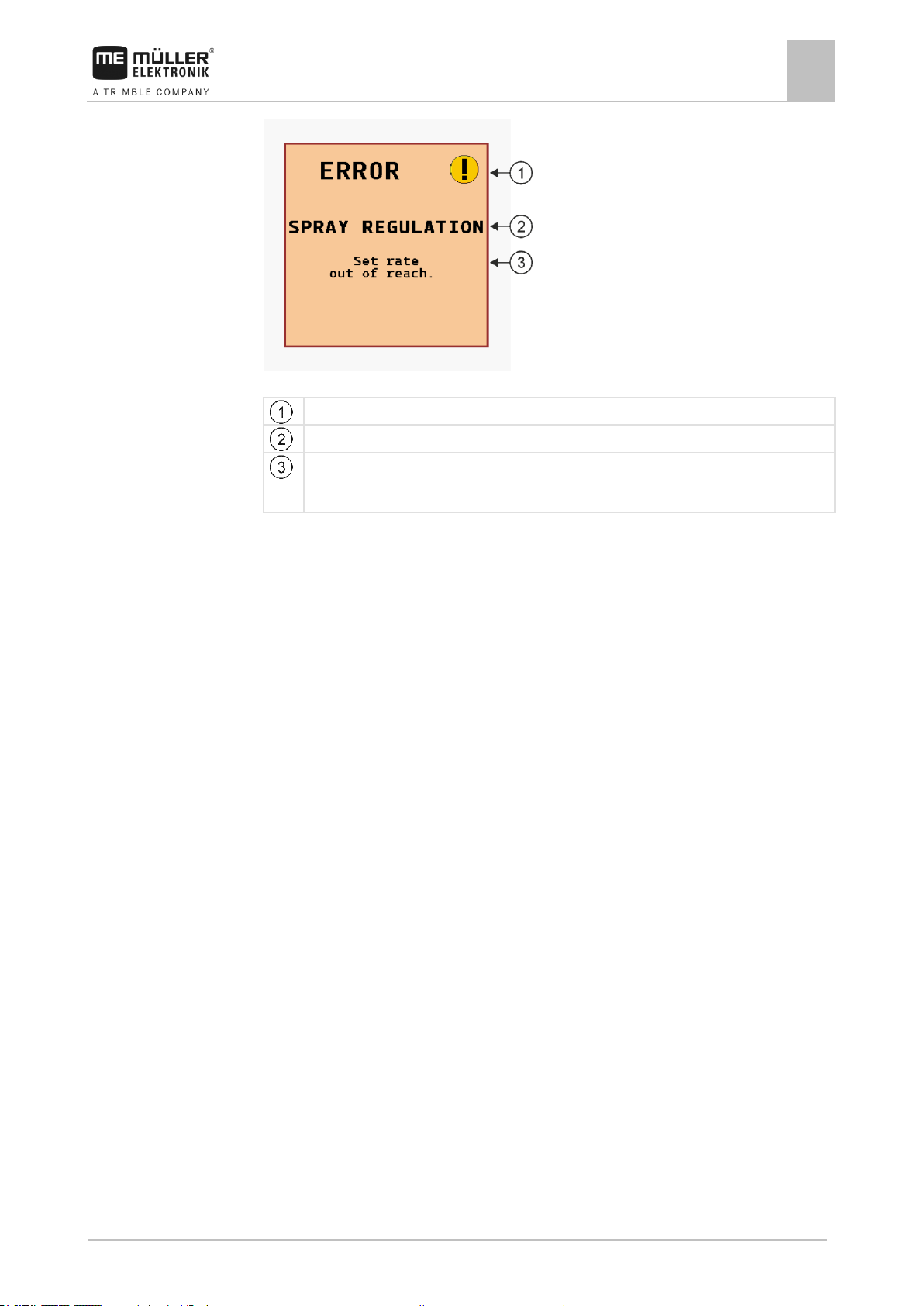
On the following diagram, you can see how the alarm messages are structured:
Page 9
For your safety
User requirements
1
30303187-02-EN
V1.20180921
9
Type of alarm
Name of the component that caused the alarm.
Problem description and solution
Information on the exact cause of an alarm message or how to rectify a fault can be found in the
section “Alarm messages”
1.5
1.6
Alarm message structure
User requirements
▪ Learn to operate the product in accordance with the instructions. Nobody must operate the
product before reading these instructions.
▪ Please read and carefully observe all safety instructions and warnings contained in these
Operating Instructions and in the manuals of any connected vehicles and farm equipment.
▪ If there is anything within these instructions that you do not understand, please do not hesitate to
contact us or your dealer. Müller-Elektronik's Customer Services department will be happy to
assist you.
Safety sign for the field sprayer
If the field sprayer is fitted with drawbar steering or with axle steering, everyone approaching the field
sprayer must be warned of possible dangers. For that reason you receive a safety sign.
1. Stick the safety sign in the appropriate place.
When attaching safety signs, observe the following:
▪ Safety signs must be attached at a visible location so that they can be seen by everyone
approaching the danger zone.
▪ If the danger area can be approached from several sides of the implement, attach the warning
signs on all implement sides.
▪ Regularly check the safety signs for completeness and legibility.
▪ Replace damaged or unreadable signs with new ones.
Page 10
1
For your safety
Safety stickers on the product
10
V1.20180921
30303187-02-EN
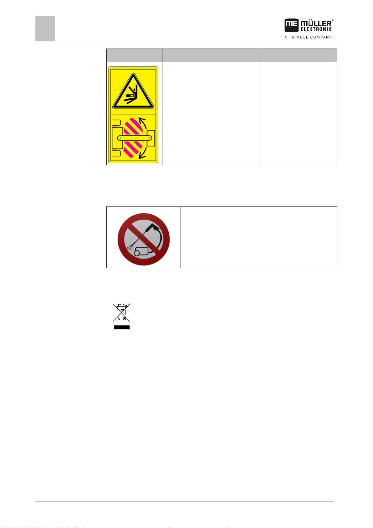
Safety sign
Where to attach
Meaning
Near the the bend area between tractor
and trailed implement.
Do not stay in the bend area
during operation.
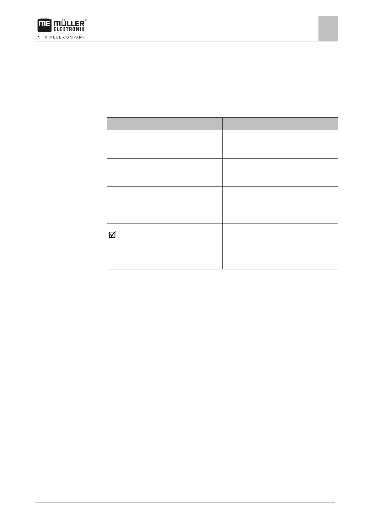
Do not clean with a high-pressure cleaner.
When it has reached the end of its service life, please dispose of this product as
electronic scrap in accordance with all applicable waste management laws.
1.7
1.8
Safety stickers on the product
Sticker on the job computer
Disposal
Page 11

For your safety
EU declaration of conformity
1
30303187-02-EN
V1.20180921
11
Product name:
ME_RE ECU-MAXI 3.0
Item number:
30303185
Variants:
30303187
Harmonised standards applied:
EN ISO 14982:2009
(EMC Directive 2014/30/EU)
Product name:
ME_RE ECU-MIDI 3.0
Item number:
30303184
Variants:
3004748207, 3004748208, 3004748209,
3004748210, 3004765002, 30193549,
3019354901, 3019354902, 3019354903,
3019354904, 3019354905, 3019354906,
3019354907, 3019354908, 3019354909,
3019354910, 30252090, 3025209001,
30285011, 3028501101, 30285015,
3028501501, 30295006, 3029500601,
3030316501, 30322453, 3032245301,
30322453, 3032245301, 30322454,
3032245401, 30322455, 3032245501,
30322456, 3032245601, 30322457,
3032245701, 30335001, 30397039, 30397040,
3040625700, 3040625701, 30481101,
30481110, 30481120, 30481130, 30481150,
30482010, 3048201001, 3053245010,
3055794701, 3055794703, 3055799001,
3062730010, 3062730011, 30720516,
3072051601, 30720522, 3072052201,
30720523, 3072052301, 30738000, 30738010,
30750001
Harmonised standards applied:
EN ISO 14982:2009
(EMC Directive 2014/30/EU)
In conformity with further EU directives:
Directive 2011/65/EU (RoHS 2)
1.9
EU declaration of conformity
Herewith we declare that the product designated below, on the basis of its design and construction in
the form brought onto the market by us, is in accordance with the relevant safety and health
requirements of the EU Directive of Electromagnetic Compatibility 2014/30/EU. If alterations are
made to the product without prior consultations with us, this declaration becomes invalid.
Page 12

2
About these Operating Instructions
Who should read these instructions
12
V1.20180921
30303187-02-EN
2
2.1
2.2
2.3
About these Operating Instructions
Who should read these instructions
These operating instructions are intended for operators of field sprayers that are equipped with the
SPRAYER-Controller MAXI 3.0 or MIDI 3.0 system with the standard configuration.
The instructions will show you:
▪ The meaning of the icons on the screen;
▪ Where to find the settings that are relevant for a function in the application;
▪ How to configure the application;
▪ How to calibrate components that need to be calibrated.
The instructions do not explain how to operate the field sprayer. It is not a substitute for the field
sprayer manufacturer's instruction manual.
Diagrams in this manual
The screenshots of the software interface are intended to serve as a reference. They help you in
finding your way around the software screens.
The information shown on the screen depends on various factors:
▪ the type of field sprayer,
▪ the configuration of the field sprayer,
▪ the condition of the field sprayer.
Possible differences:
▪ The field sprayer on the work screen has different colors on the display than in the instructions.
▪ Different background color.
▪ The icons described in the instructions appear in a different position on the screen.
▪ Some of the described functions are not available in the system.
The instructions were written for the operation of the job computer on terminals from MüllerElektronik. If the job computer is operated with other ISOBUS terminals, the screen layout and the
information represented may differ from the diagrams in this operating manual.
Directional information in these instructions
All directional information in these instructions, such as “left”, “right”, “forward”, “back”, is relative to
the movement direction of the vehicle.
Page 13
About these Operating Instructions
Layout of operating instructions
2
30303187-02-EN
V1.20180921
13
Type of depiction
Meaning
1.
2.
Actions that must be performed in succession.
⇨
Result of the action.
This will happen when you perform an action.
⇨
Result of an operating instruction.
This will happen when you have completed all
steps.
Requirements.
In the event that any requirements have been
specified, these must be met before an action
can be performed.
2.4
2.5
Layout of operating instructions
The operating instructions explain step by step how you can perform certain operations with the
product.
We use the following symbols throughout these Operating Instructions to identify different operating
instructions:
Layout of references
If any references are given in these Operating Instructions, they appear as:
Example of a reference: [➙ 13]
References can be identified by their square brackets and an arrow. The number following the arrow
shows you on what page the section starts where you can find further information.
Page 14
3
About the job computer
Job computer functions
14
V1.20180921
30303187-02-EN
3
3.1
3.2
About the job computer
Job computer functions
The SPRAYER-Controller MIDI 3.0 and MAXI 3.0 job computers are ISOBUS job computers that can
control the operation of field sprayers.
The ISOBUS job computer is the control central of the sprayer. Several sensors are connected to the
job computer, which monitor important implement parts. The job computer controls the implement
based on these signals and on the operator's specifications. An ISOBUS terminal serves as an
interface. All implement-specific data is stored in the job computer and is therefore maintained even
when changing the terminal.
System Overview
Depending on which job computer is used as the base computer for the main system, and which
additional components are installed, the overall system can have different sizes.
Example: MAXI 3.0 as the main job computer
Page 15
About the job computer
System Overview
3
30303187-02-EN
V1.20180921
15
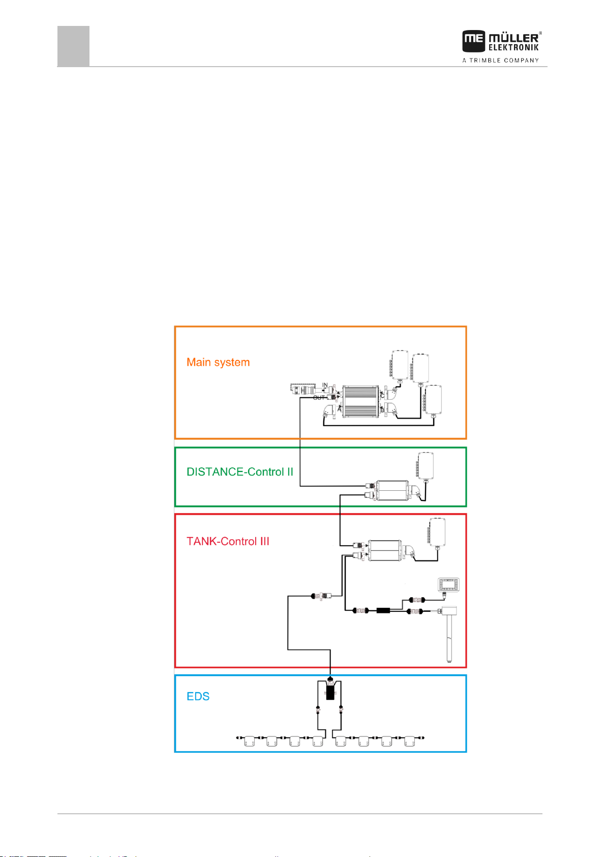
3.2.1
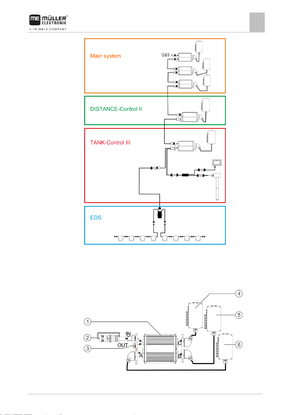
Example: MIDI 3.0 as the main job computer
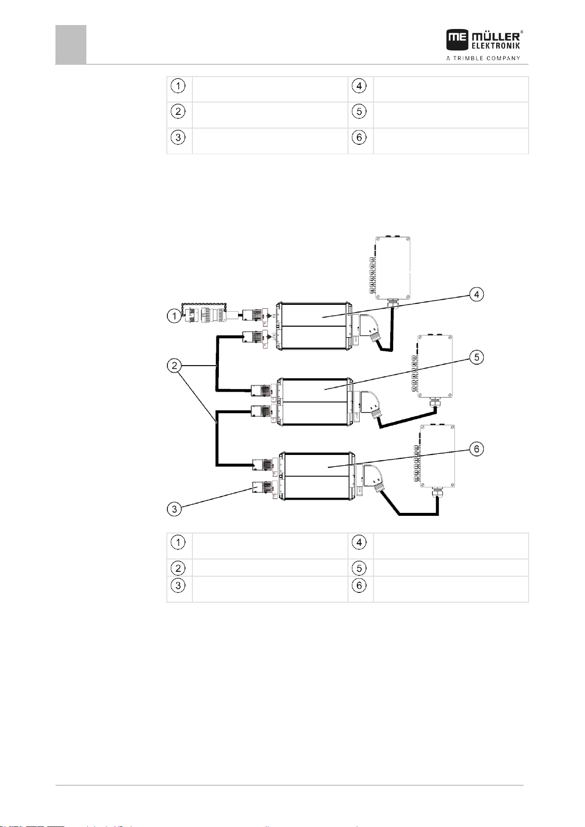
Main system - MAXI
The system can be expanded. In the basic version, it consists of a job computer that is connected to
the junction box and the ISOBUS power socket of the tractor.
Main system - Version MAXI 3.0
Page 16
3
About the job computer
System Overview
16
V1.20180921
30303187-02-EN
ISOBUS SPRAYER-Controller MAXI 3.0 job
computer
Junction box C
Connector cable for job computer to ISOBUS
Connection to ISOBUS power socket
Junction box B
Water and dust protection cap.
Otherwise, connection of extensions.
Junction box A
Connector cable for job computer to ISOBUS
Connection to ISOBUS power socket
ECU-MIDI - Master
Connector cable
ECU-MIDI - Slave
Termination plug
Otherwise, connection of extensions.
ECU-MIDI - Slave
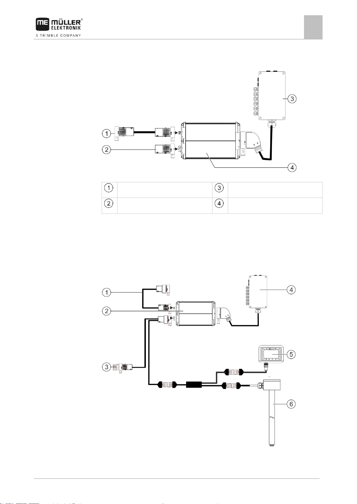
3.2.2
Main system - MIDI
The system can be expanded. The basic version consists of one to three job computers. The first job
computer is connected to the ISOBUS power socket on the tractor.
Main system of the MIDI 3.0 version
Page 17
About the job computer
System Overview
3
30303187-02-EN
V1.20180921
17
Connection to ECU-MAXI 3.0 or to the last
ECU-MIDI job computer.
Junction box
Termination plug.
Otherwise, connection of other extensions.
Job computer
3.2.3
3.2.4
Extension: DISTANCE-Control II
DISTANCE-Control II
The instructions for the DISTANCE-Control II extension can be found in the download area of our
website:
www.mueller-elektronik.de
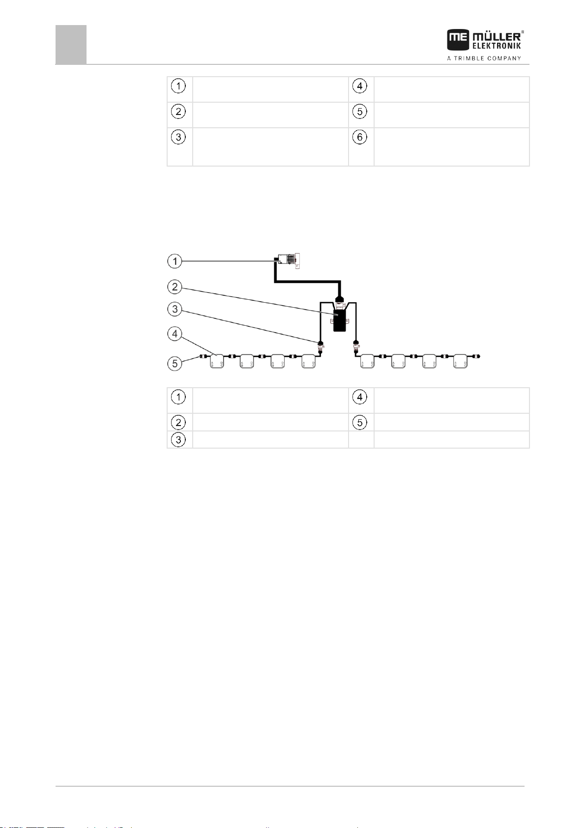
Extension: TANK-Control III
TANK-Control II
Page 18
3
About the job computer
Software extensions
18
V1.20180921
30303187-02-EN
Connection to the main system or to a system
add-on
Junction box
Job computer
TANK-Control III on-board integrated
display/controller
Water and dust protection cap or terminating
resistor.
Otherwise, connection of extensions
Fill level sensor
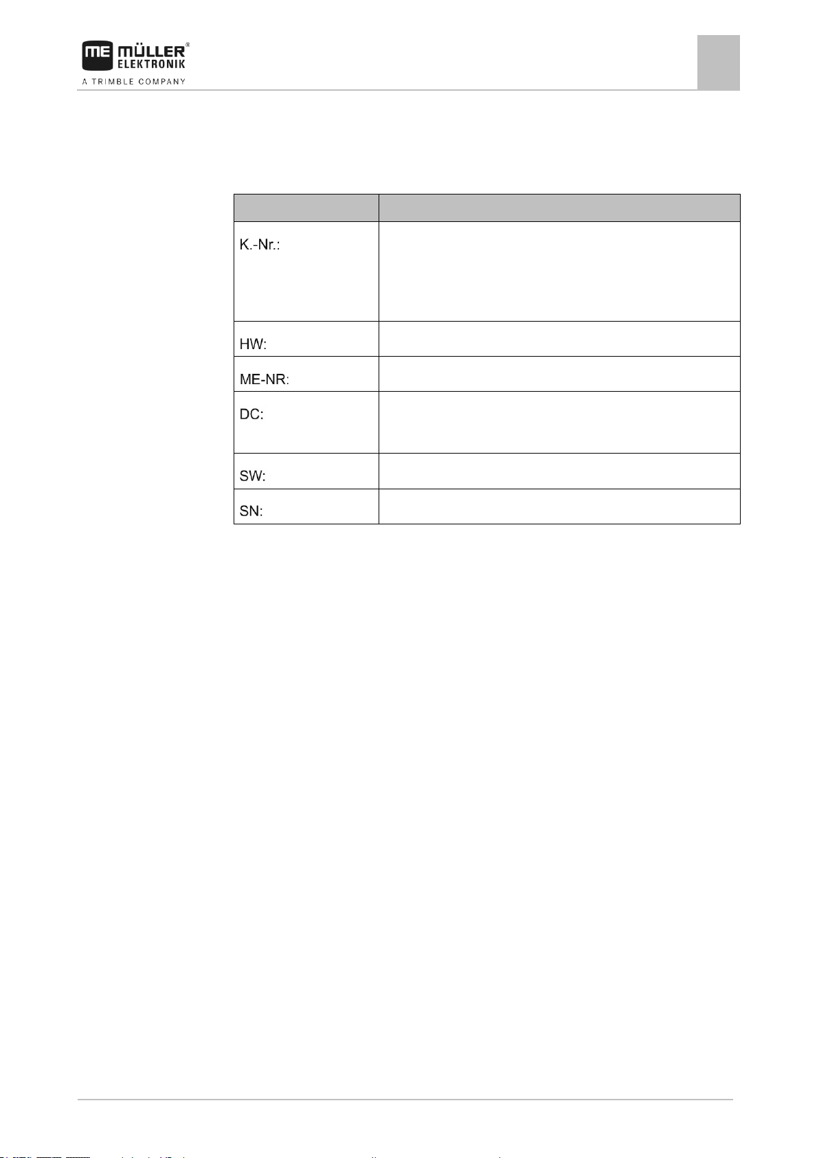
Connection to the main system or to a system
add-on
EDS modules
EDS communication module
Termination plug
Connection to the EDS bus
3.2.5
3.3
The instructions for the TANK-Control III extension can be found in the download area of our website:
www.mueller-elektronik.de
Extension: EDS
EDS
The instructions for the EDS extension can be found in the download area of our website:
www.mueller-elektronik.de
Software extensions
In addition to the functions that are configured as a standard, there are software extensions that can
be additionally activated:
▪ TRAIL-Control
▪ DISTANCE-Control
▪ VARIO-Select
The instructions for the TRAIL-Control extension can be found in the download area of our website:
www.mueller-elektronik.de
The instructions for the DISTANCE-Control extension can be found in the download area of our
website:
www.mueller-elektronik.de
More information about VARIO-Select can be found in the EDS instructions. These instructions can
also be found in the download area of our website:
www.mueller-elektronik.de
Page 19
About the job computer
Rating plate
3
30303187-02-EN
V1.20180921
19
Abbreviation
Meaning
Customer number
If the product was manufactured for an agricultural machinery
manufacturer, the agricultural machinery manufacturer's item number
will be shown here.
Hardware version
Müller-Elektronik item number
Operating voltage
The product may only be connected to voltages within this range.
Software version
Serial number
3.4
Rating plate
Abbreviations on the rating plate
Page 20
4
Mounting and installation
Installing the job computer
20
V1.20180921
30303187-02-EN
4
4.1
4.1.1
4.1.2
Procedure
Mounting and installation
Installing the job computer
Instructions for safe installation
To prevent damage to the system components, consider the following during installation:
▪ Install the job computer where it is protected from dirt. You therefore avoid unintentional cleaning
of the job computer by the implement operator using a high-pressure cleaner.
▪ In the installed position, the connectors and the pressure compensation membrane must be
facing to the side.
▪ Fasten the job computer with four fixing bolts and a flat washer (lock washers can cause cracks
in the plastic on the long term) on a conducting spot on the implement chassis. In case of
improper installation, the ESD discharges can cause malfunctions.
▪ All of the sockets and connectors that are not used must be protected from dust and water using
suitable dummy connectors.
▪ All of the connectors must be tightly sealed. This makes them waterproof.
▪ Do not use the system if some of its parts are damaged. Damaged parts can cause malfunctions
and lead to injuries. Replace damaged components or repair them if possible.
▪ Use only original components manufactured by Müller-Elektronik.
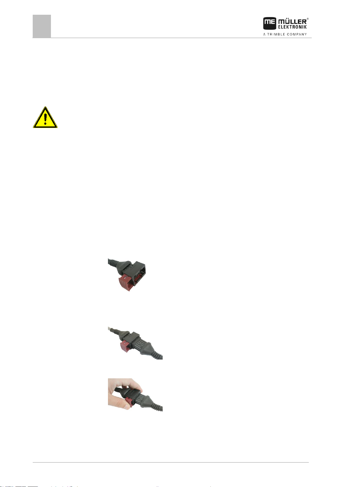
Connecting the AMP connectors
This is how to connect two AMP connectors:
1. Pull out the red locking device of the AMP socket all the way to the end.
⇨ You will hear a loud clicking sound.
⇨ The openings for inserting the locking pins of the connector are visible.
2. Insert the connector into the socket. It should be possible to easily insert the locking pins in the
openings.
⇨ The connector is loosely inserted in the socket.
3. Press in the red locking device.
⇨ You will hear a loud clicking sound.
⇨ A part of the locking device comes through to the other side of the socket.
Page 21
Mounting and installation
Connecting the job computer to the ISOBUS
4
30303187-02-EN
V1.20180921
21
4.1.3
Procedure
4.2
Procedure
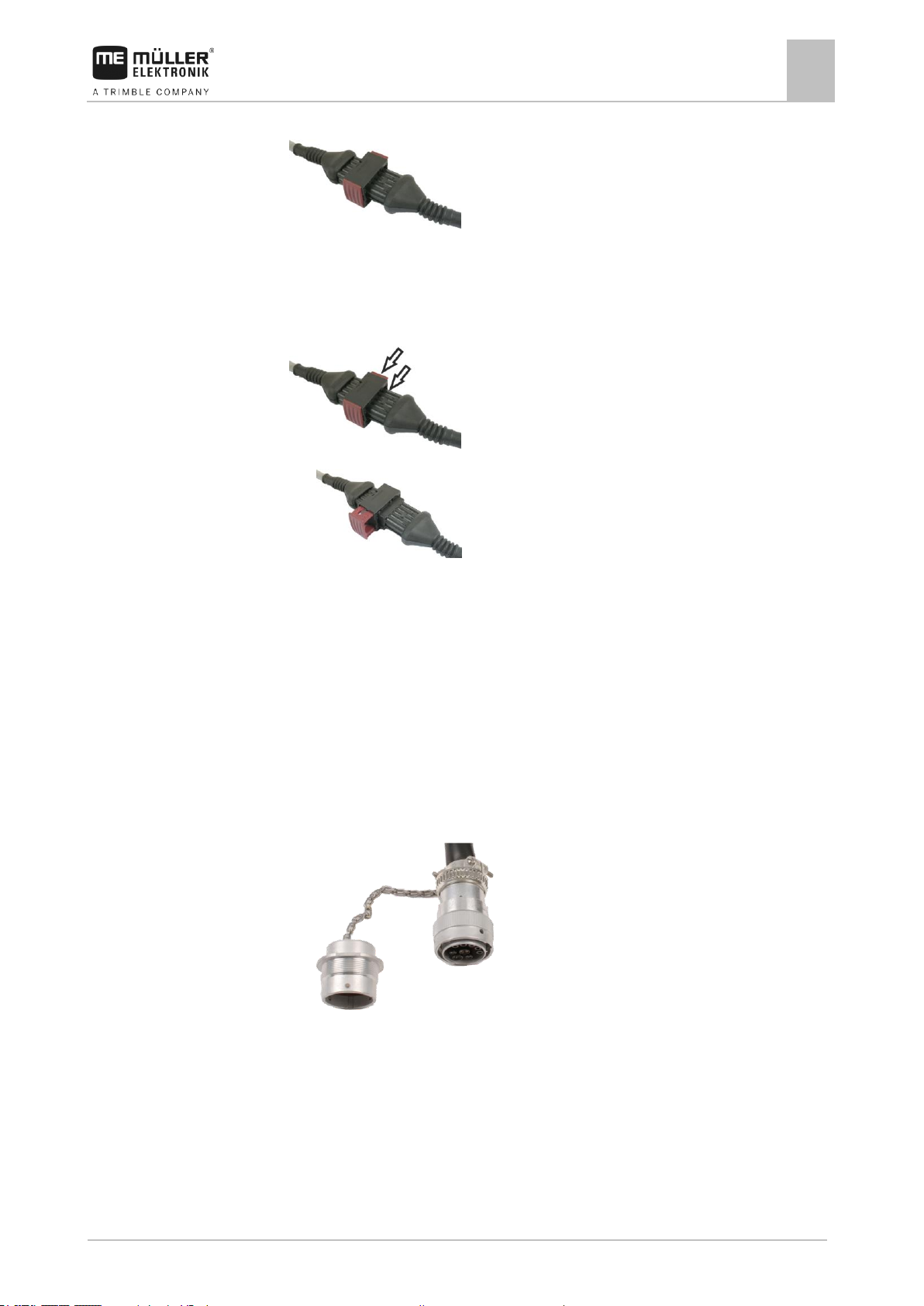
⇨ You have connected and locked the connector with the socket.
Separating the AMP connectors
This is how to separate two AMP connectors:
1. Press in both ends of the red locking device in direction of the connector.
⇨ You will hear a loud clicking sound.
⇨ The locking device has been released.
2. Pull out the red locking device of the AMP socket all the way to the end.
3. Pull the connector out of the socket.
Connecting the job computer to the ISOBUS
To connect the job computer to the power supply and to the ISOBUS terminal, you have to connect
the ISOBUS cable to an ISOBUS power socket on the tractor.
This is how to connect the job computer to the ISOBUS:
1. Take the ISOBUS cable from the job computer.
2. Unscrew the dust protection cap.
⇨
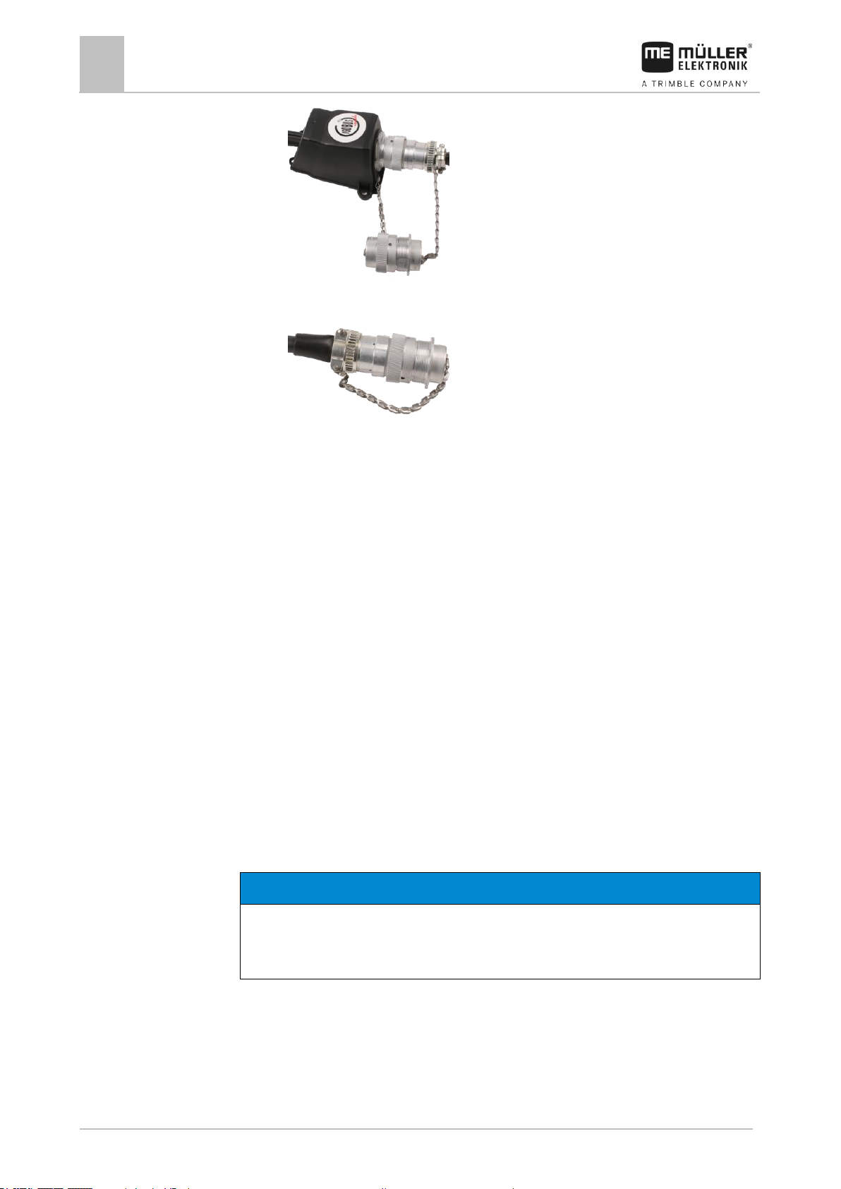
3. Insert the ISOBUS connector into the ISOBUS power socket on the tractor.
4. Lock the connector. For basic vehicle harnesses from Müller-Elektronik, turn the connector
clockwise. For other ISOBUS basic vehicle harnesses, the procedure depends on the model.
⇨ The connector fits tightly.
5. Screw the dust protection cap of the connector and the socket together.
Page 22
4
Mounting and installation
Installing the junction box
22
V1.20180921
30303187-02-EN
NOTICE
Risk of short-circuit
When exchanging the polarity of cable cores, machine sensors can be damaged by a short-circuit.
◦ Pay attention to the polarity of the cable cores and the terminals.
4.3
4.3.1
Procedure
⇨
6. When the work is completed, separate the connection and screw the dust protection cap back
on.
⇨
Installing the junction box
Take note of the following when selecting the installation location:
▪ Ensure that cables cannot be damaged by the moving implement.
▪ The cable glands must be facing downwards.
Connecting the sensors and actuators to the junction box
Every sensor and every actuator that is mentioned in the pin-out diagram must be connected to the
junction box mentioned in the pin-out diagram.
This can be done in two ways:
▪ The sensor or actuator ends with a short cable and an AMP connector.
In this case, you will receive a fitting extension cable for each sensor. You must insert the
extension cable in the junction box and connect it to the fitting terminal.
▪ The sensor or actuator ends with a long cable without a connector. You have to insert it in the
junction box and connect it to the fitting terminal.
The terminal to which you must connect the cable core depends on the respective implement and on
the type of sensor or actuator.
Please note that the cable cores for the ultrasonic sensor trigger always need to be connected to Pins
2 and 3.
1. Remove the cable coating so that all cable cores are exposed.
2. Insert the cable to the end of the coat. There should only be cable cores inside the junction box.
The cable coating must end at the junction box casing. This is the only way to ensure that you
have enough space in the junction box to be able to guide all of the cable cores to the terminals.
3. Remove the cable coating of the cable cores ca. 1 cm from the end of the cable core.
Page 23

Mounting and installation
Installing the junction box
4
30303187-02-EN
V1.20180921
23
4.3.2
Procedure
4.3.3
Procedure
4. CAUTION! Pay attention to the proper polarity of the cable cores and the terminals.
5. Connect the cable cores to the terminals.
To do so, use the information on the lid of the junction box, on the relay circuit board and in the
pin-out diagram.
6. With screw terminals, use wire end sleeves. Wire end sleeves may not be used with spring-
loaded terminal blocks.
7. Close the screw connections of the junction box.
After screwing them shut, the glands should be sealed.
8. Close unused openings in the casing of the junction box with blind caps.
Inserting the cable core into a terminal
There is at least one terminal block with three rows of terminals in the junction box.
Each terminal consists of two openings:
▪ The upper opening of the terminal opens, among other things, the lower opening.
▪ The bottom opening of the terminal serves to insert and clamp one cable core.
You have prepared a small flat screwdriver that fits the upper opening of the terminal. You only
need this screwdriver if there are wire end sleeves on the cable cores.
You have cut the cable to the proper length and have exposed the cable cores according to the
instructions, or you have a finished cable from Müller Elektronik.
The tractor engine is switched off.
The junction box is not powered.
There is no voltage on the components to be connected.
1. Find the proper connectors for the cable cores to be connected.
To do so, use the information on the lid of the junction box, on the relay circuit board and in the
pin-out diagram.
2. Insert the cable core into the opening in the lower part of the terminal. If you use wire end
sleeves, you first have to use the screwdriver.
⇨ You hear the cable core click into place.
⇨ The cable core will be held by the terminal.
⇨ You have clamped the cable core.
Connecting the junction box to the job computer
1. Connect the AMP connector of the junction box onto the proper job computer.
Page 24
5
Basic control principles
Switching on the job computer
24
V1.20180921
30303187-02-EN
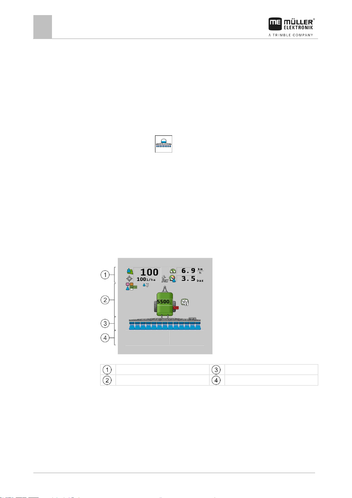
“Spray data” area
“Boom” area
Implement image with icons
Icons beside the implement image
5
5.1
Procedure
5.2
Basic control principles
Switching on the job computer
1. Connect the ISOBUS cable of the job computer to the ISOBUS connector on the tractor.
2. Start the ISOBUS terminal.
⇨ The job computer is started together with the terminal.
⇨ When starting up for the first time, the job computer initially has to transmit lots of
information to the terminal. This can take a few minutes.
⇨ When all of the data from the job computer application has been loaded, their icon appears
on the terminal: .
3. Open the job computer application. To do so, follow the instruction for the ISOBUS terminal.
⇨ The work screen of the job computer appears.
Layout of work screen
The work screen is always shown during work and informs you of the status of the field sprayer.
The work screen is divided into several areas. In each area, information on specific topics may
appear.
With the configuration of the job computer, the areas can be changed by the field sprayer
manufacturer for a specific field sprayer model. For this reason, the following graphs only show the
standard version of the overview.
Areas on the work screen
You can read about the information that appears in these areas in the following sections.
Function icons on the work screen
Function icons appear beside the work screen, which perform functions when they are tapped. Their
position and operation depend on the type of ISOBUS terminal.
In the table below, you can see the meaning of the function icons on the work screen.
Page 25

Basic control principles
Layout of work screen
5
30303187-02-EN
V1.20180921
25
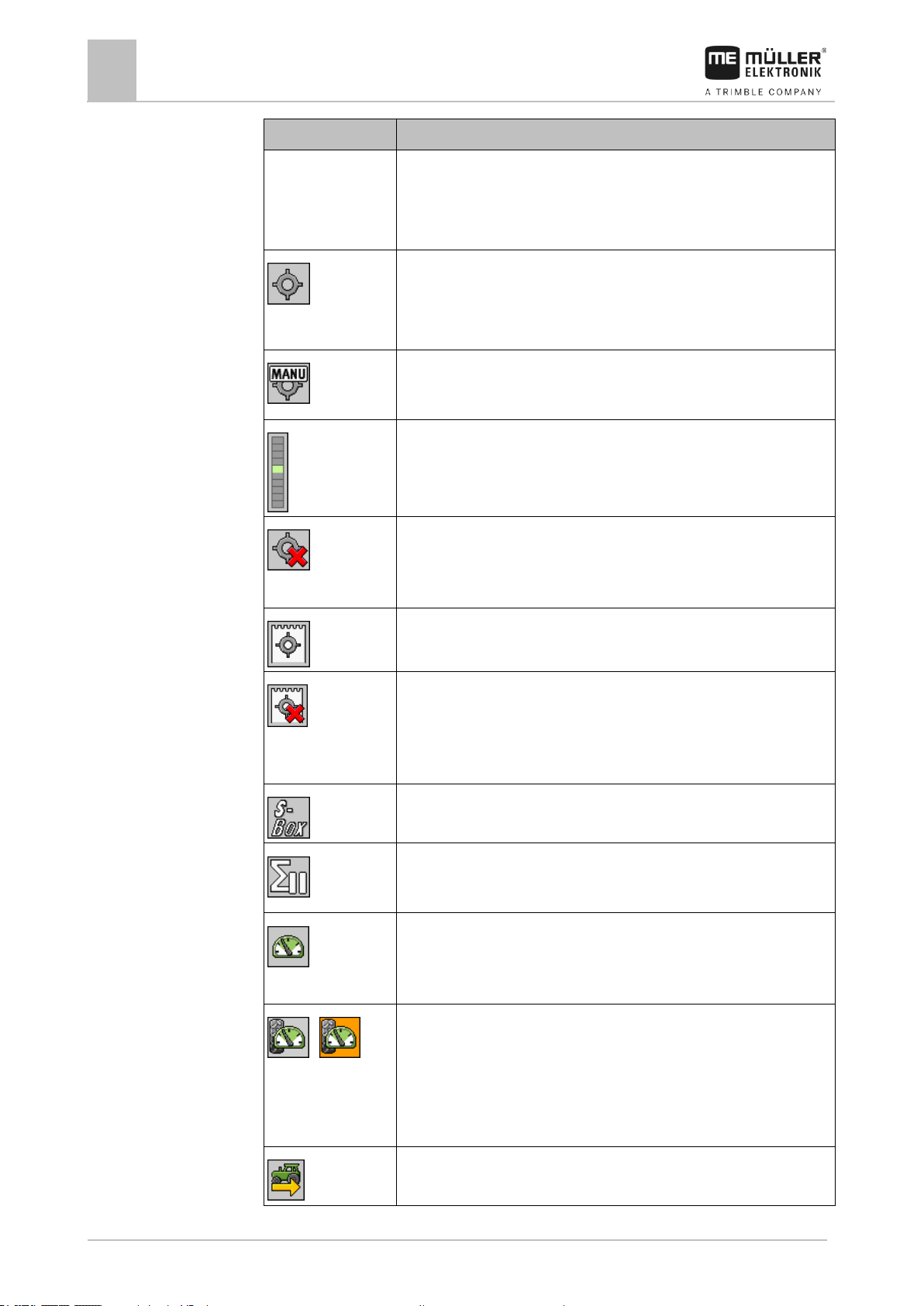
Function icon
Function
Opens the “Counters” screen.
Opens the “Parameters” screen.
Opens the “Tank Filling” screen.
Opens the “Boom Folding” screen.
Switches between manual and automatic regulation of the application rate.
Opens a screen with additional functions.
Starts and stops the drawbar steering (or stub axle steering).
Switches between two levels of icons.
Shows the next page with function icons.
Icon
Meaning
The application rate will be automatically regulated.
The current value (current application rate) appears next to it.
No flow. The main valve cannot be opened because one of the
requirements has not been fulfilled:
- Speed slower than “Sprayer off below” [➙ 56]
5.2.1
Icons
Spray data area
The following information is shown in this area:
Selected icons in the spray data area
Depending on the configuration, the following icons may appear:
Page 26
5
Basic control principles
Layout of work screen
26
V1.20180921
30303187-02-EN
Icon
Meaning
- Section status
- Target rate out of reach
- SECTION-Control has terminated the application
The application rate will be automatically regulated.
The target rate appears next to it.
See: Using Automatic mode [➙ 44]
The application rate will be manually regulated.
See: Changing the application rate in manual mode [➙ 43]
The bar graph only appears when the target rate is changed in automatic
mode using the +10% and -10% buttons. It shows the deviation from the
original target rate.
Automatic mode is deactivated. The flow will not be regulated.
The current speed is lower than the “Regulation off below” [➙ 56]
parameter and higher than “Sprayer off below” [➙ 56]
The target rate is defined by an external source: Task Controller,
prescription map, external sensor etc. See: Setting target rate [➙ 45]
- A problem has occurred with the transmission of the target rate from an
external source.
- The field sprayer is outside of the area defined in the prescription map or in
an area that should not be sprayed.
The sprayer functions will be switched on and off through an “S-Box”.
Trip counter is deactivated
See: Documenting work results [➙ 46]
Speed
If the numbers are red, it means that the regulation or the application have
been interrupted because the speed is too low.
/
(background is
flashing)
The speed signal from the tractor / ISOBUS cannot be adopted. The system
will now determine the speed using the sensor connected to the junction
box.
Ensure that the number of impulses per 100m is correctly entered.
The icon can only appear if the signal source was automatically selected.
The vehicle is driving in reverse.
Page 27

Basic control principles
Layout of work screen
5
30303187-02-EN
V1.20180921
27
Icon
Meaning
Simulated speed activated. [➙ 66]
Pressure
Picture
Status of the section valve
Status of the control/main valve
Closed valve
Closed valve
5.2.2
Illustration
Boom display area
In the boom display you find the following information:
▪ Number of sections
▪ Which sections are preselected or switched off
▪ Which sections are applying
The diagrams below show how the sections may appear in the boom display area:
Sections 1 and 2 are closed and deactivated.
Sections 1 and 2 are closed. All of the other sections are open and spraying.
When SECTION-Control is activated, the blue-red SECTION-Control icon also appears.
When SECTION-Control is not possible, this icon is red.
Each square under the boom icon represents one section valve.
Section status
Page 28

5
Basic control principles
Layout of work screen
28
V1.20180921
30303187-02-EN
Picture
Status of the section valve
Status of the control/main valve
Open valve
Closed valve
Open valve
Open valve
Closed valve
Open valve
The section is permanently deactivated
Picture
Status defined by SECTION-Control
Status of the control/main
valve
Status via S-Box or joystick
Open valve
Open valve
Closed valve
Open / closed valve
Closed valve
Closed valve
Picture
Nozzle A
Nozzles B, C, D
Open nozzle
Closed nozzle
Icon
Meaning
Sections are switched via SECTION-Control.
The SECTION-Control application has closed all sections.
Examples for the cause:
- Field sprayer is outside of the field boundary or in an area that has already
been applied
5.2.3
When the sections are automatically switched using SECTION-Control, you have to ensure that the
sections are not deactivated using an S-Box or a joystick. In this case, the section would be marked
with a red cross and remain closed.
Section status with SECTION-Control and with S-Box
Field sprayers with EDS (single nozzle switching) do not have section valves. One section consists of
multiple nozzles that are switched by EDS modules. The section icon is divided into several
segments. Each segment represents one nozzle.
Section status with EDS
Icons beside the implement image
Functions
Page 29

Basic control principles
Layout of work screen
5
30303187-02-EN
V1.20180921
29
Icon
Meaning
- Field sprayer on the headlands
Other causes are also possible.
Beacon is switched on.
(flashing)
Stirrer has been stopped. Cause: Fill level [➙ 57] is too low.
(not
flashing)
Stirrer has been stopped. Cause: Stopped by the driver.
Stirrer is working.
Fresh water tank is being emptied.
Low-pressure cleaner is being used.
High-pressure cleaner is being used.
The ring line is being rinsed.
Working lights are on.
Nozzles used in Vario mode.
Nozzles used in Select mode.
Nozzle cleaning activated.
Intended drop size with Airtec or in Vario mode.
Fan switched off.
Fan switched on.
Page 30
5
Basic control principles
Layout of work screen
30
V1.20180921
30303187-02-EN
Icon
Meaning
Permanent tank internal cleaning is activated.
Filter rinsing is activated.
Filter rinsing is activated and being used.
Compressed air rinsing is being used.
CURVE-Control is activated.
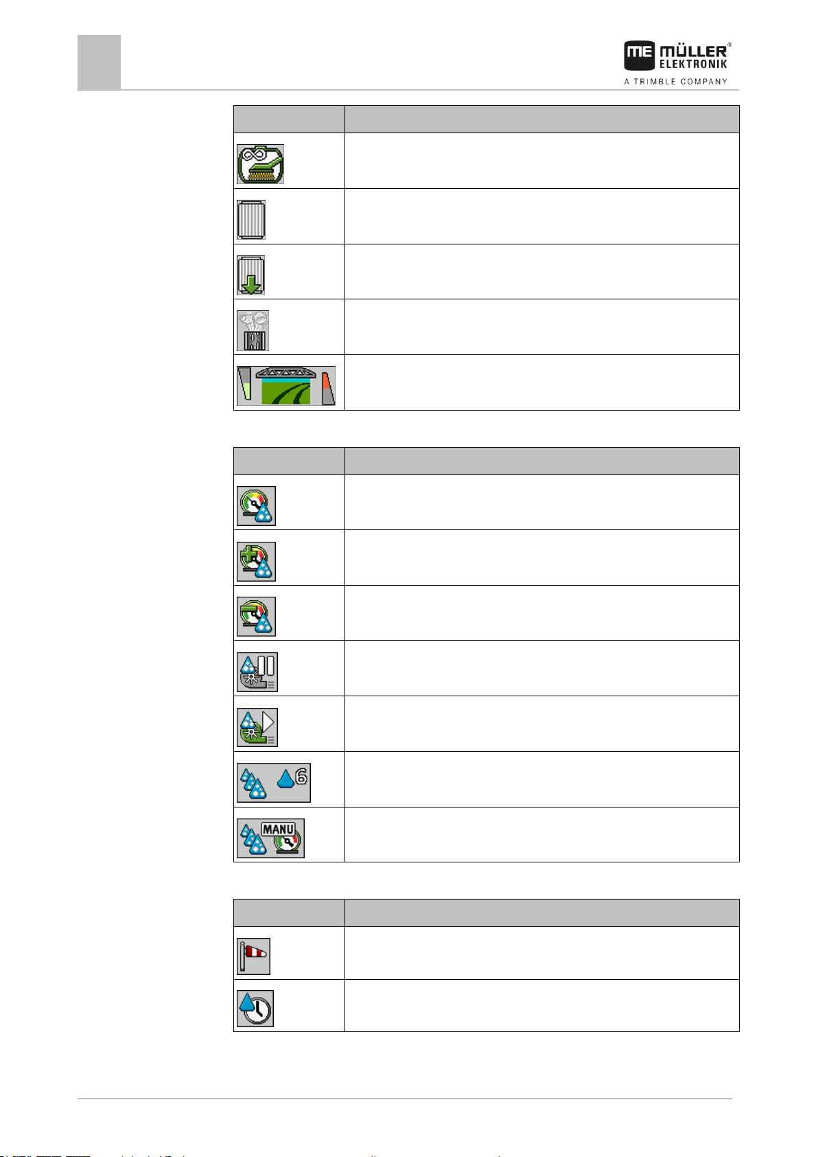
Icon
Meaning
Current air pressure
System is increasing the air pressure.
System is reducing the air pressure.
Air compressor is off.
Air compressor is on.
Manual mode is activated. The number indicates the drop size.
Drop size (automatic mode activated).
Icon
Meaning
Wind strength
Output in litres per minute
Airtec icons
Page 2 - Counters and sensors
Page 31

Basic control principles
Layout of work screen
5
30303187-02-EN
V1.20180921
31
Icon
Meaning
Area output per hour
Icon
Meaning
Tank counter:
- Current fill level (l)
- Area that can be sprayed until the tank is empty (ha)
- Distance that can be driven until the tank is empty (km)
Ring line circulation function switched on.
Icon
Meaning
DISTANCE-Control is installed but is deactivated.
The boom has to be controlled manually.
Display of the current boom slope. See: Reproducing the boom slope when
turning [➙ 40]
Meaning
Icons for drawbar steering
Icons for axle steering
No TRAIL-Control or TRAILControl in automatic mode.
TRAIL-Control is installed but is
deactivated.
TRAIL-Control is in manual
mode.
The drawbar is locked with a
pin
5.2.4
Icons on the implement image
General icons
Boom
TRAIL-Control
Page 32

5
Basic control principles
Control units
32
V1.20180921
30303187-02-EN
Meaning
Icons for drawbar steering
Icons for axle steering
The implement is steered to the
left.
The implement is steered to the
right.
5.3
Control units
The following options are available for operating the job computer:
▪ Using the function buttons on the screen
▪ Using the ME joystick
▪ Using the ME S-Box
▪ Using an external keypad
You can find more information on the configuration and operation in the following sections:
▪ Configuring the control units [➙ 58]
▪ Operating the ME joystick [➙ 47]
▪ Viewing the assignment of the joystick [➙ 49]
▪ Preview mode for the ME Joystick [➙ 48]
Page 33

Operating job computer on the field
Tank filling
6
30303187-02-EN
V1.20180921
33
Function icon
Function
Tank was fully filled up.
Set tank content to 0 liter.
6
6.1
Methods
6.1.1
Procedure
6.1.2
Operating job computer on the field
Tank filling
After each fill-up of the spray liquid tank, you enter how much water you added.
Depending on what additional equipment is fitted to your field sprayer, the process may be different.
In doing so, you can:
▪ Filling up the tank manually without additional systems
▪ Filling up the tank with TANK-Control
▪ Filling up the tank with TANK-Control and with fill stop
Filling up the tank manually without additional systems
If you fill up the tank manually without any additional systems, you need to enter the new tank content
manually on the terminal.
To enter the new tank content when you have completely refilled the spray liquid tank:
1. Switch to the “Filling - manual ” screen:
⇨ The following screen appears:
2. - Enter full tank
or
3. In the “New tank content” box, enter the tank content after refilling.
⇨ The new tank content appears in the work screen, in the tank data area.
Filling up the tank with TANK-Control
TANK-Control is a measurement system that constantly measures and displays the tank content.
Page 34

6
Operating job computer on the field
Tank filling
34
V1.20180921
30303187-02-EN
Function icon
Function
Results
Open ball valve for tank filling
- Ball valve opens.
- The following icon appears on the screen:
- Water is being pumped.
- Current tank content changes slowly.
Close ball valve for tank filling
- Ball valve closes.
Change active refill limit
Only the refill limit selected is taken into
account while filling the tank. The tank is
filled until the fill level is reached.
Procedure
6.1.3
Procedure
1. Switch to the “Filling - TANK-Control” screen:
2. - Start filling.
⇨ During the filling procedure, the following icon appears on the screen:
⇨ While filling is taking place, the filled quantity appears on the “Filling - TANK-Control” screen
on the “Current content ” line.
3. - When the tank is full, switch off pump.
Filling up the tank with TANK-Control and fill stop
If a TANK-Control with fill stop has been installed and configured on the field sprayer, you can use it.
It will stop tank filling automatically when a specified fill level is reached.
You can define up to two refill limits for tank filling. The system stops filling the tank when the tank
content reaches these refill limits.
To fill the tank with two refilling limits:
TANK-Control with fill stop is installed on the field sprayer.
1. Switch to the “Filling - TANK-Control” screen:
Page 35

Operating job computer on the field
Controlling the boom
6
30303187-02-EN
V1.20180921
35
WARNING
Injury to persons through improper operation
Every field sprayer is designed differently and must be operated differently. In this section, only the
icons that appear on the screen of the terminal can be explained.
◦ Read the field sprayer operating guide.
◦ Learn the sequence in which your field sprayer must be operated safely.
6.2
⇨ The following screen appears:
2. For Refilling limit 1 and 2, you can enter up to two fill levels at which the filling pump should be
stopped or the filling ball valve should be closed.
⇨ If you enter two refilling limits, a new function icon appears on the screen:
⇨ Press the icon to mark a refilling limit at which the pump should be stopped.
3. - Open the ball valve.
⇨ The icon appears.
⇨ Filling starts.
⇨ When the fill level defined as refilling limit 1 is reached, the ball valve closes and filling is
terminated.
⇨ If there is a second refilling limit, it will be automatically activated.
4. You can now add the spray agent and stir the tank contents.
5. Prepare the field sprayer for the second filling.
6. - Open the ball valve.
⇨ Filling starts.
⇨ When the fill level defined as refilling limit 2 is reached, the ball valve closes and filling is
terminated.
Controlling the boom
In this section you learn how to control the boom using the terminal.
Page 36

6
Operating job computer on the field
Controlling the boom
36
V1.20180921
30303187-02-EN
Function icon
Function
Lifts the boom.
Lowers the boom.
Activates and deactivates DISTANCE-Control.
Function icon
Meaning
Locks the boom
Unlocks the boom
Icon
Meaning
The boom is locked (detected by a lock sensor)
6.2.1
Path
Illustration
6.2.2
Path
Lifting and lowering the boom
This is how you reach the screen with this function:
To operate this function the user needs the ME joystick first of all.
Use the following function keys to operate the function:
On the following diagram you see how this function is shown on the work screen:
Boom is being lifted - the arrow in the middle shows the direction
“MANU” means that DISTANCE-Control is deactivated and the boom must be raised and lowered manually.
Locking the boom
This function makes it possible to lock the boom so it remains stable when the weight is unbalanced.
This is how you reach the screen with this function:
Use the following function keys to operate the function:
The following icons may appear on the screen:
Page 37

Operating job computer on the field
Controlling the boom
6
30303187-02-EN
V1.20180921
37
Icon
Meaning
The boom is being locked. The procedure is not completed.
Three-section boom
Boom part: Inner left
Five-section boom
Boom part: Unmoving part
Seven-section boom
Boom part: Inner right
Boom part: Outer left
Boom part: Middle right
Boom part: Middle left
Boom part: Outer right
Illustration
6.2.3
Path
Work screen: Boom locked
If no lock sensor is installed on the field sprayer, the icon does not appear.
Folding and unfolding the boom
This function folds the field sprayer boom in and out.
Operation depends on the following factors:
▪ Number of boom parts that can be folded in and out.
▪ Type of locking for the folding in and out of the boom.
▪ Type of field sprayer.
This is how you reach the screen with this function:
Structure of a boom
The following diagram shows the structure of booms and what the individual boom parts are called.
The diagram shows a field sprayer with a seven-part boom, but it also applies to smaller booms.
Parts of the boom on a field sprayer
Page 38

6
Operating job computer on the field
Controlling the boom
38
V1.20180921
30303187-02-EN
Folding parts of the boom
Icon: Boom section is being folded in or out
The arrows appear for folding boom sections and indicate the direction of movement.
Icon
Meaning
The boom is at the same height as the boom top height sensor. Requirement:
The boom top height sensor is installed.
Directional arrow
Arrow pointing inwards means: Fold in
Arrow pointing outwards means: Fold out
Sections of the boom marked in grey are not folded in or out with this function icon
Sections of the boom marked in white are folded in or out with this function icon
Function
Three-section boom
Five-section boom
Seven-section boom
Fold inner boom
symmetrically
Unfold inner boom
symmetrically
Fold boom in the
middle symmetrically
Illustration
Function icons
Screen
Representation of the boom on the “Boom folding” screen
On the following diagram, you see how a seven-part boom is shown on the function icons.
Use the following function keys to operate the function:
Page 39

Operating job computer on the field
Controlling the boom
6
30303187-02-EN
V1.20180921
39
Function
Three-section boom
Five-section boom
Seven-section boom
Unfold boom in the
middle symmetrically
Unfold outer left boom
Unfold outer right boom
Fold inner and middle
boom symmetrically
Unfold inner and middle
boom symmetrically
Block boom section
Function icon
Function
Raises the right wing.
Raises the left wing.
Lowers the right wing.
Lowers the left wing.
Raises both wings symmetrically.
Lowers both wings symmetrically.
6.2.4
Path
Procedure
Raising and lowering the wings (tilting up / down)
The system is capable of raising or lowering wings independently or simultaneously.
This is how you reach the screen with this function:
Use the following function keys to operate the function:
1. Press the function key with the desired function.
⇨ The wings will be moved.
2. Keep function button pressed until the boom reaches the desired angle.
3. Release function key.
Page 40

6
Operating job computer on the field
Controlling the boom
40
V1.20180921
30303187-02-EN
Function icon
Function
Slopes the boom to the right. It will be raised on the left.
Slopes the boom to the left. It will be raised on the right.
Function icon
Meaning
Activates the function. Each time the button is pressed, the target position
of the boom (white arrows) changes.
6.2.5
Path
Illustration
6.2.6
Mode of operation
Sloping the boom
This is how you reach the screen with this function:
To operate this function the user needs the ME joystick first of all.
Use the following function keys to operate the function:
On the following diagram you see how this function is shown on the work screen:
Slope boom: raise on the left, lower on the right
Slope boom: lower on the left, raise on the right
Reproducing the boom slope when turning
This function assists you when working on slopes.
The boom is sloped when working on a hillside. The function saves the angle of slope.
After a turning manoeuvre, the angle of slope is reproduced when the field sprayer is travelling in the
opposite direction.
When turning on a slope, you can press a button to slope the boom in the opposite direction.
Use the following function keys to operate the function:
Page 41

Operating job computer on the field
Controlling the boom
6
30303187-02-EN
V1.20180921
41
Function icon
Meaning
Slopes the boom manually. By pressing this button, the automatic
reproduction of the slope angle is terminated.
Current direction of movement of the boom.
Current boom position.
Target boom position.
Current angle of the angle sensor on the
sloping cylinder.
Icon
Meaning
White arrows: Target position is horizontal.
Angle sensor: Horizontal position has been reached.
Boom is sloped to the right. Function is deactivated.
Boom is sloped to the right. However, it should be automatically sloped to
the left. The system will move the boom in this direction.
Current position: Boom is sloped to the right
Target position: Sloped to the left.
Reproduce boom angle: activated
Boom is sloped to the right. However, it should be automatically moved to
a horizontal position. The system will move the boom in this direction.
Illustration
Procedure
When the function is active, the current setting is shown above the boom on the work screen.
Depending on the configuration, the following icons may appear:
Examples:
You have calibrated the boom potentiometer (slope angle sensor). [➙ 76]
1. Drive across the slope gradient with the field sprayer.
2. Position the boom parallel to the sloped ground.
3. – Press on the headlands before the turning manoeuvre.
⇨ The current angle will be saved.
⇨ - Two white arrows pointing down appear.
⇨ The system returns the boom to the horizontal position.
⇨ While the boom is moving, a green arrow appears on the work screen.
⇨ When the boom is horizontal, the icon appears.
Page 42

6
Operating job computer on the field
Starting application
42
V1.20180921
30303187-02-EN
6.3
Procedure
Immediate application
4. Turn only when the boom is horizontal.
5. - Press once after the turning manoeuvre.
⇨ The job computer slopes the boom in the opposite direction until the previously saved angle
is reached on the other side.
⇨ While the boom is moving, a green arrow appears on the work screen.
⇨ The function switches off if you change the boom angle manually.
Starting application
To start the application:
The tractor with the field sprayer is on the field.
You have configured the job computer.
You have folded out the boom.
1. Ensure that all prerequisites have been fulfilled.
2. - Start application
⇨ In manual mode:
The field sprayer starts the application.
Spray cones appear under the boom icon:
⇨ In automatic mode:
The field sprayer will be prepared for application.
As long as the field sprayer does not move, the following icon appears in the work screen:
3. In automatic mode:
Start driving and exceed the minimum speed for the automatic regulation (parameter:
“Regulation off below”).
⇨ As soon as the minimum speed is exceeded, the field sprayer starts the application.
Spray cones appear under the boom icon:
⇨ You have started application.
There may be situations where you want to start spraying while the sprayer is still at a standstill. For
example, when you have stopped on the field.
To start immediate application in automatic mode:
The tractor with the field sprayer is on the field.
You have configured the job computer.
You have folded out the boom.
Page 43

Operating job computer on the field
Regulating the application rate
6
30303187-02-EN
V1.20180921
43
Function icon
Function
Switches the mode between manual and automatic.
6.4
6.4.1
Automatic mode is activated.
1. Press and hold the application button on the joystick for three seconds.
⇨ The field sprayer starts the application.
Spray cones appear under the boom icon:
2. Start driving within 5 seconds and exceed the minimum speed for the automatic regulation
(parameter: “Regulation off below”). Otherwise, the application will be automatically terminated.
Regulating the application rate
Types of regulation
Depending on the field sprayer equipment, the application rate regulation system can either control
the opening of a control valve or the speed of a centrifugal pump.
Work modes
You can regulate the application rate manually or you can leave the regulation to the job computer:
▪ In manual mode, you can control the opening of the control valve with two buttons.
▪ In automatic mode, the job computer regulates the opening of the control valve (or the pump
speed) such that the application rate defined as the set rate is reached.
Use the following function keys to operate the function:
You will learn how to operate the system in the following sections.
Changing the application rate in manual mode
When the field sprayer is in manual mode, the application is not regulated according to a specified
rate. The application rate must be set manually instead.
The application rate must be regulated manually when the following icon appears in the spray data
area of the work screen:
Application in manual mode
Please note that the pressure is also automatically changed when you change the application rate.
To operate this function the user needs the ME joystick first of all.
Use the following function keys to operate the function:
Page 44

6
Operating job computer on the field
Regulating the application rate
44
V1.20180921
30303187-02-EN
Function icon
Function
Increases the application rate.
Reduces the application rate.
Icon on the
work screen
Meaning
Field sprayer can apply.
The speed of the field sprayer is lower than “Regulation off below”.
Field sprayer can apply. The flow will not be regulated. The control valve remains
in the last known position until the speed changes.
The speed of the field sprayer is below “Sprayer off below”.
The main valve is closed automatically.
Regulation is not possible because the application was deactivated by the
SECTION-Control app.
6.4.2
Requirements
Mode of operation
Using Automatic mode
In automatic mode, the job computer regulates the degree of opening of the control valve and the
main valve on the manifold such that the target rate defined for the application rate can be reached.
You are in automatic mode when one of the following icons appears in the spray data area of the
work screen:
To use automatic mode, the following conditions must be fulfilled:
▪ Target rate has been entered.
▪ Flow meter is calibrated.
▪ A speed signal is available.
▪ Working width is set.
▪ The speed of the field sprayer is higher than the speed for the “Regulation off below” parameter.
▪ The parameter “Regul. factor” has been set.
In the following cases, the flow is automatically adjusted:
▪ Speed of the field sprayer has changed.
▪ Number of switched-on sections has changed.
▪ You have changed the target rate manually.
▪ The application rate has been changed by the information from the application map.
The speed and precision of the regulation depends on the value of the “Regul. factor” parameter.
You can change the target rate manually while driving in Automatic mode.
To operate this function the user needs the ME joystick first of all.
Page 45

Operating job computer on the field
Regulating the application rate
6
30303187-02-EN
V1.20180921
45
Function icon
Function
Increases the target rate by 10%.
Reduces the target rate by 10%.
Restores the target rate back to 100%.
Changes to the entered “Rate 1”.
Changes to the entered “Rate 2”.
Procedure
6.4.3
Methods
Illustration
To change the target rate during work:
1. - Activate automatic steering.
2. - Open main valve.
⇨ Spray cones appear under the boom icon on the work screen. Still, the sprayer is not
spraying.
⇨ As long as you are at a standstill, the sprayer cannot start spraying. See icons: and
3. Exceed the speed defined in the “Regulation off below” parameter.
⇨ The sprayer begins adjusting the application rate to the defined target rate.
4. or - Press to change the target rate.
⇨ The degree of change appears on the work screen.
5. - Restores the original target rate.
6. If you have entered several target rates in the configuration, you can also use the function icons:
and to switch among the target rates.
Setting target rate
The target rate is the quantity of spray liquid you want to apply per hectare.
The job computer will attempt to maintain this rate during the work.
There are several ways to specify the rate:
▪ Enter rate on the “Parameters” screen. [➙ 56]
▪ The target rate can be adopted from external sources using the “ISOBUS-TC” app:
– from tasks,
– from prescription maps,
– from external sensors.
Page 46

6
Operating job computer on the field
Operating sections
46
V1.20180921
30303187-02-EN
Function icon
Function
Closes section valves from left to right.
Closes section valves from right to left.
Opens section valves from left to right.
or
When all of the section valves are closed, then the first section valve is
opened from the left.
Closes section valves from right to left.
or
When all of the section valves are closed, then the first section valve is
opened from the right.
6.4.4
6.5
6.6
Target rate from parameters
Target rate from an external source
Target rates from external data sources have a higher priority than the target rate entered in the job
computer. For this reason, you do not have to adjust the “Rate” parameter when you are working with
prescription maps.
As an option, you can enter up to three different target rates in the job computer. To do so, use the
“Rate 1” and “Rate 2” parameters in addition to the “Target rate” parameter.
Stopping application
You can stop application in the following ways:
▪ - Close main valve.
▪ or - Close the section valves consecutively.
▪ Drive slower than the set minimum speed (only in automatic mode).
Operating sections
To operate this function the user needs the ME joystick first of all.
Use the following function keys to operate the function:
Documenting work results
You can document your work in the “Counters” screen.
On the “Counters” screen, there are two types of counter:
Page 47

Operating job computer on the field
Operating the ME joystick
6
30303187-02-EN
V1.20180921
47
Function icon
Function
Resets the “Volume” counter.
Resets the “Area” counter.
Resets the “Distance” counter.
Resets the “Work time” counter.
Pressed briefly: Continue to the total counters
Pressed long: Back to the work screen
Clears the contents of the displayed trip counter.
Stops the trip counter.
- The documentation of the work will be stopped until the terminal is
restarted or the function button is pressed again.
- The icon is flashing on the work screen:
Next trip counter. (Optional function)
Activates the trip counter. (Optional function)
Previous trip counter. (Optional function)
6.7
▪ Trip counter – documents the work until it is deleted.
▪ Total counter – documents the work since initial start-up.
The “Counters” screen has the following information:
▪ Quantity - Applied quantity.
▪ Area - Applied area.
▪ Distance – Distance driven during the application.
▪ Work time – Total duration of the application.
Use the following function keys to operate the function:
Operating the ME joystick
With the ME joystick, you can activate and deactivate the field sprayer functions.
For example:
▪ Open main valve
▪ Switch off sections from left to right
▪ Lifting and lowering the boom manually
Page 48

6
Operating job computer on the field
Operating the ME joystick
48
V1.20180921
30303187-02-EN
Position of the switch
Color of the LED
Red
Yellow
Green
Side-mounted switch
Assignment
Procedure
6.7.1
Mode of operation
Procedure
Three functions are assigned to each button. The position of the side switch determines the function
that is executed when a button is pressed.
The button assignment depends on the configuration of the field sprayer.
To operate the ME joystick:
The work screen is called up.
1. Move the side switch into the desired position and hold.
⇨ The LED on the ME joystick lights up in the corresponding colour.
2. Press button with the desired function.
⇨ The function is executed.
Preview mode for the ME Joystick
The preview mode of the joystick can only be used when your joystick works with the AUX1 auxiliary
protocol.
When pressing the button for the first time, the preview mode shows the button assignment on the
screen. This makes it easier for beginners to activate the right function. As a standard, preview mode
is deactivated on new job computers.
When you press a joystick button for the first time after starting, no function will be executed. The
button assignment of the joystick appears on the screen instead. The display remains until the time
set in the configuration has expired.
If you press a joystick button during the display, its function will be executed. (Assignment remains on
the screen until the time expires).
From now on, you can operate the joystick without the help display appearing.
The help display only appears again of you press a button and simultaneously move the rocker
switch on the side to a different position.
To activate the preview mode:
1. Switch to the “PARAMETERS” screen:
> > >
2. For the “ME Joystick” parameter, set the value to “ME Joystick”.
⇨ The “Joystick assistant” parameter appears.
3. Set the check mark for the parameter.
4. If necessary, change the display time.
Page 49

Operating job computer on the field
Using foam markers
6
30303187-02-EN
V1.20180921
49
Function icon
Meaning
Switches the left foam marker on and off.
Switches the right foam marker on and off.
6.7.2
Procedure
6.8
Path
Illustration
Viewing the assignment of the joystick
The assignment of the joystick can only be viewed when your joystick works with the AUX1 auxiliary
protocol.
To display the button assignment on the screen:
ME Joystick is configured. [➙ 58]
1. - Press until the button appears.
2. - Press.
⇨ The button assignment appears:
3. , , - Press to view the assignment on each level.
4. You can also activate the Preview mode [➙ 48].
Using foam markers
Foam markers produce foam that can be applied by the field sprayer driver on the field at the ends of
the boom. The driver can then drive parallel to the foam.
To access the controls:
> .
Use the following function keys to operate the function:
Page 50

6
Operating job computer on the field
Operating additional functions
50
V1.20180921
30303187-02-EN
Function icon
Function that can be activated or deactivated
,
Lightning 1 and 2
Beacon
Ring line circulation system
Cleaning the ring line circulation system
Tank cleaning
Permanent tank internal cleaning
Spray agent pump
Stirrer
Low pressure cleaner
Lift mixing hopper
Lower mixing hopper
High pressure cleaner
6.9
Path
Foam marker activated on both sides of the boom
Operating additional functions
Additional functions are manufacturer-specific functions. They can only be activated or deactivated by
pressing a button.
All functions are in the additional screens.
To access the controls:
or
Additional functions
Page 51

Operating job computer on the field
Regulating the drop size with AIRTEC
6
30303187-02-EN
V1.20180921
51
Function icon
Function that can be activated or deactivated
Empty fresh water tank
Fill fresh water tank
Compressed air flushing
Filter rinsing
Left foam marker
Right foam marker
, , ,
Four hydraulic functions that can be freely connected
Drop size increase for AIRTEC
Drop size decrease for AIRTEC
Lower the transport hooks for securing the boom.
Important:
For the system to be able to work optimally at the beginning of the field, the
speed should be the same when switching off the sprayer at the end of the
field as well as when switching on at the beginning of the field, and should
correspond as closely as possible to the normal spraying speed.
Icon
Meaning
Current air pressure
6.10
Requirements
Mode of operation
Icons
Regulating the drop size with AIRTEC
AIRTEC is a system for regulating the drop size on field sprayers. It adds compressed air to the spray
mixture directly in the nozzle at a ratio calculated by the job computer.
Minimum equipment of the field sprayer:
▪ Nozzles with air support
▪ Air compressor: on the field sprayer or on the tractor.
The job computer regulates the air pressure such that the drop size always remains constant. Even
when the spray pressure changes.
Airtec icons
Page 52

6
Operating job computer on the field
Regulating the drop size with AIRTEC
52
V1.20180921
30303187-02-EN
Icon
Meaning
System is increasing the air pressure.
System is reducing the air pressure.
Air compressor is off.
Air compressor is on.
Manual mode is activated. The number indicates the drop size.
Drop size (automatic mode activated).
Function icon
Meaning
Switches between manual and automatic mode.
Starts and stops the air compressor mounted on the field sprayer.
(optional)
Larger drops
Smaller drops
Increases the pressure.
Reduces the pressure.
Calls up the screen with settings.
Smaller nozzle.
Bigger nozzle.
6.10.1
Switching the air compressor on and off
The system works with two types of compressors:
▪ Compressor on the field sprayer - is switched on and off by the job computer using a function
button.
Page 53

Operating job computer on the field
Regulating the drop size with AIRTEC
6
30303187-02-EN
V1.20180921
53
NOTICE
Liquid in the compressed air system
Damage to the compressed air system
◦ Only switch the air compressor off when the AIRTEC nozzles are not installed. If AIRTEC
nozzles are installed, the air compressor must be activated.
Procedure
Procedure
6.10.2
Procedure
6.10.3
Procedure
▪ Compressor on the tractor
To switch the air compressor on:
1. - Press.
⇨ This icon appears on the work screen:
⇨ Air compressor will be switched on.
To switch the air compressor off:
1. - Press.
⇨ This icon appears on the work screen:
⇨ Air compressor will be switched off.
AIRTEC in automatic mode
In automatic mode, select the drop size that you want to achieve. The air pressure is adjusted so that
this drop size is reached.
AIRTEC nozzles are installed.
AIRTEC is configured. [➙ 75]
Air compressor is on.
1. - Setting the drop size.
⇨ The set drop size appears on the work screen:
AIRTEC in manual mode
In manual mode, you control the air pressure manually. The air pressure changes the drop size.
1. - Set the air pressure.
⇨ The target air pressure appears beside the icon:
⇨ As long as the compressor is regulating the air pressure, + or - appears beside this icon:
Page 54

6
Operating job computer on the field
Using the ISB short-cut button
54
V1.20180921
30303187-02-EN
6.11
Using the ISB short-cut button
If you are using your terminal with an ISB short-cut button, you can use it to directly terminate various
functions of the sprayer, depending on the configuration.
The following functions can be configured:
▪ Sprayer
All of the spraying functions are stopped.
▪ TRAIL-Control
All TRAIL-Control functions are stopped.
▪ DISTANCE-Control
All DISTANCE-Control functions are stopped.
Page 55

Configuring the job computer
Entering field sprayer parameters
7
30303187-02-EN
V1.20180921
55
You have to configure the following
Section with more information
Field sprayer parameters
Entering field sprayer parameters
Field sprayer geometry
Entering the field sprayer geometry [➙ 75]
Configuring external operating devices
Configuring the control units [➙ 58]
Collaboration with the terminal
Configuring the communication with the terminal
(Condensed Work State)
Calibrating the flow meter
Calibrating the flow meter [➙ 59]
Configuring the speed sensor
Selecting and configuring the speed sensor [➙
64]
Configuring sections
Configuring sections [➙ 66]
7
7.1
When to enter?
Procedure
7.1.1
Configuring the job computer
The following table contains the most important configuration steps that must be performed during
initial start-up. If your system includes additional components, such as TRAIL-Control, DISTANCEControl, AIRTEC, TANK-Control etc., these must also be configured and calibrated.
Entering field sprayer parameters
Enter the parameters in the following cases:
▪ Prior to initial start-up.
▪ When the field sprayer parameters change.
To change the value of a parameter:
1. Switch to the “PARAMETERS” screen:
⇨ The “Parameters” screen appears.
⇨ A small rectangular box with a value appears under each parameter.
2. Select this box to change a parameter.
⇨ Screen for data input or keyboard appears.
3. Enter desired value.
⇨ The new value appears on the “Parameters” screen.
The parameters appearing on your screen depend on the type and configuration of your field sprayer.
“Nozzle” parameter
Colour of the activated nozzles.
The colours are specified by the ISO standard. The nozzles can also be calibrated. [➙ 69]
This parameter only appears on systems that do not have a flow meter. With these systems, a
pressure sensor for determining the application rate is used instead.
Page 56

7
Configuring the job computer
Entering field sprayer parameters
56
V1.20180921
30303187-02-EN
7.1.2
7.1.3
7.1.4
7.1.5
7.1.6
7.1.7
7.1.8
“Target Rate” parameter
The quantity entered as the target rate will be applied when the field sprayer is working in automatic
mode.
You can configure up to three different target rates, between which you can switch on the work
screen.
“Working Width” parameter
Field sprayer working width.
“Wheel Impulses” parameter
Number of impulses the wheel sensor sends to the job computer on a 100m distance. Used to
calculate the speed.
The number is determined by the wheel sensor calibration.
“Minimum Pressure” parameter
This setting defines the minimum pressure up to which the spraying pressure is optimal.
If the spraying pressure drops below the defined pressure, an alarm is issued.
If no pressure sensor is installed on your sprayer, you must enter “0” as the value.
“Maximum Pressure” parameter
This setting defines the maximum pressure up to which the spraying pressure is optimal.
If the spraying pressure increase beyond the defined pressure, an alarm is issued.
If no pressure sensor is installed on your sprayer, you must enter “0” as the value.
“Sprayer off Below” parameter
(Minimum working speed)
If the field sprayer falls below the minimum working speed, the following happens:
▪ Application will be switched off automatically.
▪ The work screen displays the icon
When the value is set to 0, this function is deactivated.
“Regulation off Below” parameter
If the field sprayer falls below this speed, the following happens:
▪ The flow will no longer be regulated and the flow remains unchanged.
▪ Manual mode will be activated.
▪ The work screen displays the icon
Page 57

Configuring the job computer
Entering field sprayer parameters
7
30303187-02-EN
V1.20180921
57
7.1.9
7.1.10
7.1.11
7.1.12
7.1.13
7.1.14
7.1.15
When the value is set to 0, this function is deactivated.
This parameter must be higher or the same as the “Sprayer off below” parameter.
“Regulation Factor” parameter
In Automatic mode, the spray pressure will be adapted to the current speed of the field sprayer. The
adjustment should ensure that the volume of spray liquid that is applied is exactly what you defined in
the target rate. The regulation factor plays a decisive role here.
The regulation factor adjusts the reaction speed of the regulation:
▪ The higher the regulation factor, the faster the spray pressure is adjusted.
▪ The lower the regulation factor, the more slowly the spray pressure is adjusted.
When setting the regulation factor, you can pay attention to the following:
▪ If, during movement at constant speed, the current application volume jumps around the target
value, you need to reduce the regulation factor.
▪ If, when speed is changing, the application volume does not adjust to the rate quickly enough,
you need to increase the regulation factor.
“Tank Size” parameter
Size of the tank for the spray liquid.
“Tank level alarm” parameter
When the volume of spray mixture in the tank falls below this value, an alarm message appears on
the screen.
“Impulses Main Flow” parameter
Number of impulses the flow meter sends to the job computer per one liter of liquid. Used to calculate
the application rate.
The number is determined by the flow meter calibration.
“Stirring off Below” parameter
With this parameter, you can set the fill level below which the stirrer should be switched off.
The implement manufacturer (not the user!) can also define whether the stirrer should be switched on
automatically when the job computer is started.
“Maximum Wind Speed” parameter
Wind sensor must be installed.
If the maximum wind speed is exceeded, an alarm will be triggered.
“Extremity nozzles set” parameter
With this parameter you can specify which extremity nozzles are mounted on the boom. More about
this in section: Extremity nozzles [➙ 72]
Page 58

7
Configuring the job computer
Configuring the control units
58
V1.20180921
30303187-02-EN
7.1.16
Procedure
7.1.17
7.1.18
7.1.19
7.2
“Pump” parameter
When the pump speed is higher than the maximum permitted pump speed, an error message
appears. This allows drivers to have better control of their work and prevent the pump from being
damaged when the speed is too high.
The parameter includes two values:
▪ “Current”
Indicates what the maximum pump speed is currently set to.
▪ “Target”
Used to change the maximum pump speed.
To save the current pump speed as the maximum permitted speed:
1. Highlight “Set value” line.
2. Run the pump speed up to the desired value.
⇨ The current pump speed will be shown on the “Set value” line.
3. - Press.
⇨ The pump speed from the “Set value” line appears in the “Current” line. In this way it has
become the maximum permitted pump speed.
“Section Control” parameter
Manner in which the sections are switched on and off.
▪ “Sequential mode” [➙ 46]
This type is intended for normal spraying work. It is also suitable for spraying on wedge-shaped
areas and strips that are narrower than the working width of the field sprayer.
“Filling Mode” parameter
With this parameter, you can define whether you want to use TANK-Control for filling.
▪ “Manual” - For field sprayers without TANK-Control.
▪ “TANK-Control” - Activates TANK-Control.
“Circulation Type” parameter
▪ “Non constant pressure”
For manifolds without the “Constant pressure” function.
▪ “Constant pressure”
For manifolds with the “Constant pressure” function.
Configuring the control units
The joystick and S-Box control units are configured on a screen.
▪ “Joystick” parameter:
– “Without Joystick”: Joystick is not connected. All functions will be controlled using the
terminal or an ME S-Box.
– “ME Joystick”: ME Joystick is being used.
Page 59
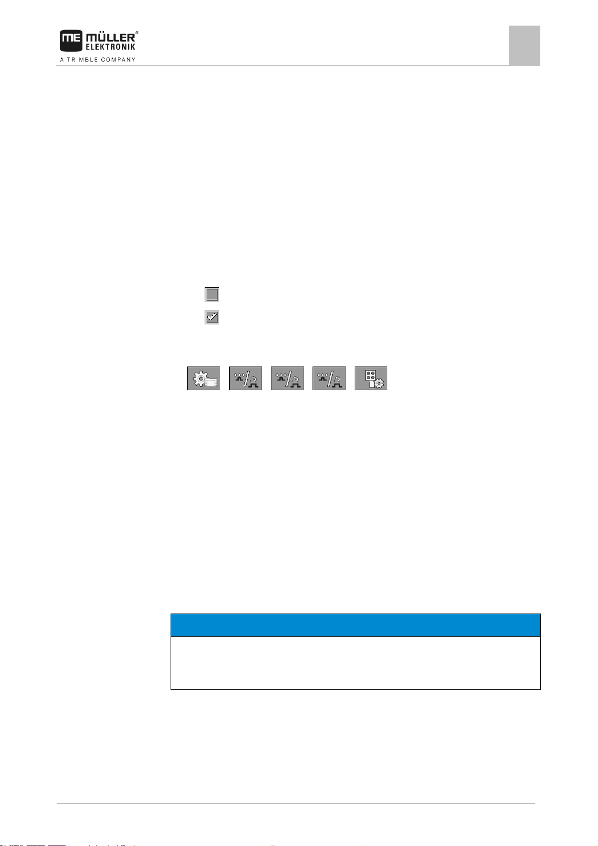
Configuring the job computer
Calibrating the flow meter
7
30303187-02-EN
V1.20180921
59
NOTICE
Imprecise calibration
If the calibration is imprecise, the calculations will be very inaccurate and the application imprecise.
◦ Calibrate the flow meter very precisely.
Procedure
7.3
When should you
calibrate?
Methods
7.3.1
Mode of operation
– “Ignore ME Joystick”: The joystick should be ignored. Setting for the auxiliary job computer
for systems with two job computers.
– “ME-Joyst. only On/Off”: Setting for the auxiliary job computer, if on/off (section main switch)
is deactivated on the S-Box.
▪ “ME S-Box” parameter:
– “Without ME S-Box”: No S-Box connected.
– “ME S-Box”: Default setting when the S-Box is available.
– “Ignore ME S-Box”: For systems with two job computers, this is the setting for the first job
computer. The signals from the ME S-Box are rejected because this job computer should be
operated with the joystick.
– “ME SBox without On/Off”: Setting for the second job computer.
▪ “Joystick assistant” parameter:
– - Preview mode deactivated
– - Preview mode [➙ 48] activated Beside this, you can set the display time for the
button assignment.
1. Switch to the “PARAMETERS” screen:
> > > >
⇨ The “AUX controls” screen appears.
2. Configure parameter.
Calibrating the flow meter
Because the number of impulses per liter can change during the lifespan of a flow meter, calibration
must be carried out in the following cases:
▪ Prior to initial start-up.
▪ At the start of each season.
▪ When you detect deviations between the quantity actually sprayed and the quantity displayed.
▪ When you have replaced or repaired the flow meter.
There are two ways you can calibrate the flow meter:
▪ The tank method – it is time-consuming, but precise.
▪ The nozzle method – it is not as precise as the tank method, but is less time-consuming.
Calibrating the flow meter with the tank method
With the tank method, a large quantity of water will be applied from the tank over a specific time.
The flow meter measures the impulses during this time.
After the application, you must enter the quantity of water that has been applied.
Page 60

7
Configuring the job computer
Calibrating the flow meter
60
V1.20180921
30303187-02-EN
WARNING
Spray liquid or spray liquid residues
Danger of poisoning or chemical burning
◦ Clean the spray liquid tank thoroughly prior to calibration. The field sprayer must be free of
spray liquids or spray liquid residues.
◦ Use only clear water during calibration.
◦ Wear required protective equipment.
Procedure
The computer calculates the number of impulses per litre.
All sections are selected.
Manual mode is activated (the icon appears in the “Spray data” area of the work screen).
The tank is filled with clear water. For this, you need several hundred litres of clear water.
You have the option of weighing the entire trailer or measuring the volume of water applied with
another method.
Pump is switched on.
1. Ensure that all prerequisites have been fulfilled.
2. Weigh the tank.
3. Switch to the “CALIBRATION” screen:
> > >
⇨ The following screen appears:
4. - Select the tank method.
Page 61

Configuring the job computer
Calibrating the flow meter
7
30303187-02-EN
V1.20180921
61
7.3.2
Mode of operation
⇨ The following screen appears:
5. - Start application
⇨ During application, the number of impulses will be counted on the “CALIBRATION – Main
flow meter” screen.
6. Apply a few hundred litres. Do not fully empty the tank. This prevents air bubbles from forming
and distorting the results.
7. - Stop the application.
⇨ The application will be stopped.
⇨ No impulses are counted on the display.
8. - Stop calibration.
9. Weigh the tank.
10. Enter the applied quantity in litres on the “Enter water volume” line.
11. - Exit the screen.
⇨ You have calibrated the flow meter with the tank method.
Calibrating the flow meter with the nozzle method
When calibrating the flow meter using the nozzle method, you determine the average quantity of the
liquid applied through a nozzle in a specific time.
When calibrating using this method, you must apply clean water over the entire working width and
measure the applied quantity on different nozzles using a measuring cup.
The flow meter measures the impulses during this time.
When you have finished the application, you must enter how much water was applied on average by
one nozzle in one minute.
The computer calculates the number of impulses per litre.
Page 62

7
Configuring the job computer
Calibrating the flow meter
62
V1.20180921
30303187-02-EN
WARNING
Spray liquid or spray liquid residues
Danger of poisoning or chemical burning
◦ Clean the spray liquid tank thoroughly prior to calibration. The field sprayer must be free of
spray liquids or spray liquid residues.
◦ Use only clear water during calibration.
◦ Wear required protective equipment.
Procedure
Manual mode is activated (the icon appears in the “Spray data” area of the work screen).
You have prepared a measuring cup to measure the applied quantity.
You have prepared a stopwatch to be able to count one minute precisely.
All of the sections are preselected, and the sprayer can apply over the entire working width.
The tank is filled with clear water.
The set working width is correct.
The number of nozzles per section and the number of sections is entered correctly.
1. Ensure that all prerequisites have been fulfilled.
2. Switch to the “CALIBRATION” screen:
> > >
⇨ The following screen appears:
3. - Select the nozzle method.
Page 63

Configuring the job computer
Calibrating the flow meter
7
30303187-02-EN
V1.20180921
63
7.3.3
Procedure
7.3.4
⇨ The following screen appears:
⇨ The current flow appears on the “Measured flow” line.
4. - Start application
5. Go to one of the nozzles and carefully collect the water sprayed for 60 seconds by using the
prepared measuring cup.
6. Write down the applied water volume.
7. Repeat the last two steps on several nozzles.
8. Calculate and write down an average of several measurements.
9. - Stop application.
⇨ The application will be stopped.
10. - Stop calibration.
⇨ On the „3. Enter real volume per nozzle ” line, an input box appears.
11. Enter the average applied volume in litres in this box.
12. - Exit the screen.
⇨ The value of the “Impulses main flow” parameter will be updated.
⇨ You have calibrated the flow meter with the nozzle method.
Manually entering the number of impulses per liter for the flow meter
If you know the precise number of impulses per liter for the flow meter, you can enter this value
manually.
1. Switch to the “FLOW METER” screen:
> >
2. Enter number of impulses per litre on the “Impulses main flow” line.
Combining the flow meter with the pressure sensor
If a pressure sensor is installed on the sprayer, you can combine the regulation via the flow meter
and the pressure sensor. This enables more stable regulation even at low flow rates.
Page 64

7
Configuring the job computer
Selecting and configuring the speed sensor
64
V1.20180921
30303187-02-EN
Procedure
7.4
7.4.1
Procedure 1
1. Switch to the “FLOW METER” screen:
> > >
2. Activate the “Combined flow/pressure regulation” parameter.
3. Configure parameter.
“Flow Tolerance” parameter
Enter a percent value at which the system should switch to pressure regulation. If, for example, the
current flow rate drops below 60 % of the desired flow rate, the system switches to pressure
regulation.
“Threshold Flow” parameter
Enter the limit range of your flow meter. If the flow rate drops below the limit range or increases
beyond the limit range, the system switches to pressure regulation.
Selecting and configuring the speed sensor
You must enter the source from which the job computer shall obtain the current speed.
The configuration procedure can differ depending on the speed source.
Selecting the speed source
Supported speed sources:
▪ “Sensor” – Sensors that are installed on the field sprayer and connected to the job computer:
– Examples: Wheel sensor, radar sensor, impulse-transmitting GPS speed sensor
– Configuration: Configure the number of impulses per 100 meters.
▪ “ISOBUS” – Sensors that are installed on the tractor and whose signal is received through the
ISOBUS.
– Examples: GPS receiver, wheel sensor on the tractor, signal socket
– Configuration: For systems without the option of selecting the sensor input, the “Wheel
impulses” parameter must be set to 0.
▪ “Auto” – Some systems enable automatic detection of the speed source.
– Mode of operation: If a speed signal is detected on the ISOBUS, this speed will be used as
a basis. In the case of signal failure, the job computer will take the impulses from the sensor
connected to the job computer as a basis for determining the speed.
– Configuration: For systems that have two sensor types, it is recommended to calibrate the
sensor that is connected to the job computer. In other cases, set the “Wheel Impulses”
parameter to 0.
To configure the speed source:
1. On the work screen, press the following keys successively:
> .
⇨ The “Speed” screen appears.
2. Configure the “Speed source” parameter.
Page 65

Configuring the job computer
Selecting and configuring the speed sensor
7
30303187-02-EN
V1.20180921
65
Procedure 2
7.4.2
Procedure
7.4.3
Signal sources
If the “Speed source” parameter does not appear on the “Speed” screen, and the speed signal should
be received through the ISOBUS, proceed as follows:
The speed signal can be received through the ISOBUS.
1. Switch to the “PARAMETERS” screen:
2. Set the “Wheel impulses” parameter to “0”.
Calibrating the speed sensor with the 100m method
When calibrating the speed sensor with the 100m method, you determine the number of impulses
received by the speed sensor in a distance of 100m. When you know the amount of impulses, the job
computer can calculate the current speed.
If you know the number of impulses for the wheel sensor, you can also enter this number manually.
You can enter different pulse values for up to three different wheels.
Wheel sensor, radar sensor or GPS speed sensor is installed on the field sprayer.
A distance of 100m has been measured and marked. The distance must correspond to the field
conditions. It should therefore lead over a meadow or a field.
The tractor with connected implement is ready for a 100m drive and is at the start of the marked
distance.
1. Ensure that all prerequisites have been fulfilled.
2. Switch to the “CALIBRATION – wheel impulses” screen:
> >
3. - Start calibration.
⇨ The following function icons appear:
- Stop calibration.
- Abort calibration.
4. Drive the previously measured 100m distance and stop at the end.
⇨ During the drive, the currently determined impulses are displayed.
5. - Stop calibration.
6. - Exit the screen.
⇨ The number of impulses appears on the “Wheel impulses” line
Configuring the reverse driving sensor
If the trailed implement or the tractor sends a reverse driving signal through the ISOBUS, the job
computer can use this signal to adjust its regulating behaviour when driving in reverse.
You can find more information in this section: Configuring automatisms when driving in reverse
The following signal sources are possible:
Page 66

7
Configuring the job computer
Configuring sections
66
V1.20180921
30303187-02-EN
Procedure
7.4.4
Procedure
7.5
7.5.1
When to enter?
▪ “None” - The job computer should not expect a reverse driving signal. Even if a reverse driving
signal is transmitted through the ISOBUS, the job computer will ignore the signal.
▪ “ISOBUS” - The reverse driving signal is sent by the tractor or a different job computer through
the ISOBUS.
▪ “Sensor” - A reverse driving sensor is connected to the junction box or cable harness of the job
computer.
To select the reverse signal source:
1. Switch to the “SPEED” screen:
> .
2. Select the box below the “Reverse drive sensor” parameter.
⇨ The available signal sources appear. See the description at the beginning of this section.
3. Select the signal source.
4. Restart the job computer.
“Simulated Speed” function
The simulated speed function is only used during tests and when looking for faults. It simulates the
movement of the implement when the implement is at a standstill.
You can also use this function for technical inspection of field sprayers.
By activating the “Simulated speed” function, it is possible for customer service employees to check
the correct functioning of a sensor.
By default, the value is set at 0 km/h and the function is switched off.
After restarting the computer, the function is always deactivated.
The most recently set value is saved and used for the next activation.
1. Switch to the “Speed” screen:
> .
2. - Activate the simulated speed. By pressing again, you can deactivate the function.
⇨ The “Simulated speed” line appears.
3. Enter the speed to be simulated on the “Simulated speed” line.
4. - Exit the screen.
⇨ The set speed and the flashing icon appear on the work screen.
Configuring sections
Entering the number of nozzles per section
You must enter the number of nozzles installed on each section.
▪ Prior to initial start-up.
▪ If the number of nozzles in a section changes.
Page 67

Configuring the job computer
Configuring sections
7
30303187-02-EN
V1.20180921
67
Procedure
7.5.2
Results
Procedure
1. Switch to the “Boom” screen:
> .
⇨ The “BOOM” screen appears.
⇨ Here, you can see the set working width, the number of sections and the number of nozzles.
The two last values may not be changed.
2. - Press.
⇨ The “NUMB. OF NOZZLES” screen appears.
3. Here, you can enter the number of nozzles for each section. Multiple nozzle holders count as
one nozzle in this case.
⇨ With each change, the number of nozzles changes on the “BOOM” screen.
Switching sections off permanently
You can permanently switch off any section. This is useful, for example, if the tramlines on the field
are designed for a smaller field sprayer than yours.
Switching off the outer sections has the following effects:
▪ With TRACK-Leader: The newly calculated working width will not be taken into account for the
calculation of the headland width.
▪ With SECTION-Control: After switching off the outer sections, you will need to change the “Line
spacing” parameter so that the distance between the guidance lines matches the actual working
width. You cannot change the “Working width” parameter.
▪ The actual working width changes. However, as the field sprayer has not changed:
– Do not change the “Working width” parameter.
– Do not change the field sprayer geometry.
Permanently switched off sections are marked in white on the work screen
1. Switch to the “Boom” screen:
> .
⇨ The “BOOM” screen appears.
2. - Press.
⇨ The “SECTIONS” screen appears.
⇨ For each section, you can see one of the following icons:
- Section activated
- Section deactivated.
3. For each section, you can select and change this icon.
Page 68

7
Configuring the job computer
Configuring sections
68
V1.20180921
30303187-02-EN
7.5.3
7.5.4
Procedure
7.5.5
Procedure
Permanently switching off a section using a sensor
If a sensor for monitoring the unfolding of boom sections is installed on the boom, sections can be
automatically permanently switched off.
This enables the use of a field sprayer with multiple working widths without having to change the
configuration each time.
System delay when switching the sections
For SECTION-Control to be able to open and close the section valves precisely, you must determine
how many milliseconds are required for the liquid to travel from the valve to the nozzle. Afterwards,
the job computer will switch the valves earlier or later accordingly.
You are using the automatic SECTION-Control.
1. Read the operating instructions for the TRACK-Leader app to find out how to determine the
delay times.
2. Determine the delay times.
3. Open the job computer application.
4. On the work screen, press:
> > > > >
⇨ The “SECTION-Control” screen appears:
5. Enter the determined delay times under “Delay on start” and “Delay on stop”.
“Delay on Start” parameter
Time that elapses between the opening of a section valve and the emergence of liquid out of the
nozzles.
Rule of thumb:
▪ If the sprayer switches too late, increase the value of the parameter.
▪ If the sprayer switches too early, decrease the value of the parameter.
“Delay on Stop” parameter
Time during which the nozzles continue spraying after the valve has been closed.
Rule of thumb:
▪ If the sprayer switches too late, increase the value of the parameter.
▪ If the sprayer switches too early, decrease the value of the parameter.
Changing the display of areas on the terminal
You can make different settings to change the display of the areas on the terminal, e.g. for the
TRACK-Leader application.
1. On the work screen, press:
> > > >
2. Configure the “Zero target rate areas” parameter. The following configuration options are
available to you:
Page 69

Configuring the job computer
Configuring the nozzles - for field sprayers with pressure sensor regulation
7
30303187-02-EN
V1.20180921
69
Sections off
Applied on
the map
Function
deactivated
---
The sections are not closed when the application rate is 0 l/ha.
Everything is recorded in the process.
activated
deactivated
The sections are closed when the application rate is 0 l/ha.
Only the applied areas are recorded.
activated
activated
The sections are closed when the application rate is 0 l/ha.
Both the applied areas and areas where nothing was applied will be
recorded.
This is the standard setting when using SECTION-Control.
Function icon
Meaning
Changes the calculated data
7.6
7.6.1
Configuring the nozzles - for field sprayers with pressure sensor
regulation
By configuring the nozzle type, the job computer can calculate the current application rate based on
the measured spray pressure.
You only have to configure the nozzles if a pressure sensor is installed on the field sprayer.
If no pressure sensor is installed on the field sprayer and the application rate is regulated only
through the flow rate, then you do not need to configure the nozzles.
Nozzle assistant
The nozzle assistant serves the following purposes:
▪ To show how the nozzle type affects the possible application rates and speeds.
▪ To help with the correct selection of the installed nozzle type.
▪ To change the target rate.
Determination of possible application rates
Page 70

7
Configuring the job computer
Configuring the nozzles - for field sprayers with pressure sensor regulation
70
V1.20180921
30303187-02-EN
Selected nozzle
Here, you can enter:
- The intended working speed
- The optimal pressure for the nozzle
Here, you can see which application rates are possible with this nozzle at the set working speed.
Selected nozzle
Here, you can enter:
- The intended application rate This is adopted directly from the “Rate” parameter.
- The optimal pressure for the nozzle
Here, you can see the speed at which this application rate can be reached.
Procedure
Procedure
Determination of the fitting nozzles
To calculate the application rate that can be reached with a nozzle at a given pressure:
1. Switch to the “Nozzle assistant” screen:
> .
2. - Press for the speed icon to appear in the “User data” area.
3. Select the box with the nozzle colour to select a nozzle.
⇨ The list contains all standard nozzles and four positions for the configuration of custom
nozzles.
4. Enter the intended working speed in the box.
5. In the area, set the optimal pressure range that enables the
intended drop size with the selected nozzle. This value can be found on the nozzle data sheet.
⇨ Note: The pressure range set here will not be adopted for the application. During operation,
you must ensure for yourself that the sprayer is working in the intended pressure range.
⇨ In the “Results” area, the possible application rates appear.
If the calculated application rate is too high or too low:
▪ Change the working speed.
▪ Install different nozzles. Perform the calculation for the new nozzle colour.
The calculation can be performed based on the intended application rate:
Page 71

Configuring the job computer
Configuring the nozzles - for field sprayers with pressure sensor regulation
7
30303187-02-EN
V1.20180921
71
Selected nozzle
Nozzle output at 3 bar - Result of the
calibration
Current nozzle output. When you change the
pressure, the newly calculated nozzle output
appears.
For non-standard nozzles, the calibration must
be repeated at a different pressure. This
pressure should be about as high as the
intended working pressure.
WARNING
Spray liquid or spray liquid residues
Danger of poisoning or chemical burning
◦ Clean the spray liquid tank thoroughly prior to calibration. The field sprayer must be free of
spray liquids or spray liquid residues.
◦ Use only clear water during calibration.
◦ Wear required protective equipment.
7.6.2
Illustration
Procedure
1. - Press for the icon to appear in the “User data” area.
2. Enter the intended application rate in the field.
3. Enter the pressure range for the nozzle colour.
4. In the “Results” area, you can see the speed at which the application rate can be achieved.
Calibrate the nozzles
“Calibration” screen
Calibrate a standard nozzle as follows:
The tank is filled with clear water.
There are no spray liquid residues in the tank or the pipelines.
Page 72

7
Configuring the job computer
Extremity nozzles
72
V1.20180921
30303187-02-EN
7.7
1. - On the work screen, switch the application mode to manual.
2. - Start application
3. and - Set the spray pressure to 3 bar.
4. Using a measuring cup, collect the water from several nozzles for one minute each.
5. Calculate average application rate.
6. - Stop the application.
7. - Activate automatic mode.
8. Switch to the “Calibration” screen:
> >
9. On the “Nozzle” line – select nozzle for calibration. Standard nozzles are referred to by their
colours.
10. In the box below the “New reference point” line, enter the calculated average quantity in l/min.
11. For undefined nozzles, you must also enter the nozzle's minimum output in the “2nd reference
point” parameter. To do so, you must repeat the procedure at a different pressure.
⇨ You have calibrated the selected nozzle.
Extremity nozzles
Extremity nozzles are nozzles with a different spray pattern from the other nozzles on the boom. They
can either restrict the spray width, in which case they are used for spraying field edges (corner
nozzles), or increase the spray width of a section (wide area nozzles).
Before using extremity nozzles, note the following:
▪ Wide area nozzles or corner nozzles can be installed as extremity nozzles. You can choose the
icon used to represent the extremity nozzle on the work screen.
▪ Extremity nozzles can be installed at the outer end of any section.
▪ The width of the spray cone is irrelevant for the ISOBUS job computer. It is never detected and is
not taken into account in the following calculations:
– when calculating the working width,
– when calculating the applied quantity,
– when calculating the tank content.
▪ The TRACK-Leader and SECTION-Control applications from Müller-Elektronik do not take
account of the width of the spray cone from the extremity nozzles; they treat them as normal
nozzles.. If you are using these applications, you may have to adjust the working width manually.
Page 73

Configuring the job computer
Extremity nozzles
7
30303187-02-EN
V1.20180921
73
“Extremity nozzles set” parameter
Currently selected extremity nozzle pair
Extremity nozzles left and right
Installation site for the left and right extremity
nozzle
Icon
Meaning
No nozzle
Corner nozzle
Wide area nozzle
7.7.1
Procedure
Configuring the extremity nozzles
Screen for configuring the extremity nozzles
“Extremity nozzles set” parameter
You can define up to three sets of extremity nozzles via the “Extremity nozzles set” parameter. For
each set, you can define the installation site and the relevant work screen icon.
Meaning of the icons
To configure the extrem. nozzles modes:
1. Call up the screen with the extremity nozzle settings:
> >
Page 74

7
Configuring the job computer
Extremity nozzles
74
V1.20180921
30303187-02-EN
Corner nozzles on sections 1 and 14
Wide area nozzles on sections 1 and 14
Corner nozzles on sections 3 and 12
Wide area nozzles on sections 3 and 12
7.7.2
⇨ The following screen appears:
2. On the “Extremity nozzles set” line, enter the set of extremity nozzles for which you want to enter
settings. For example “2”:
⇨ The saved settings appear on the screen.
3. Select one of the nozzle icons under the boom icon.
4. Select the type of extremity nozzle required.
⇨ An alarm message appears. This message informs you that the job computer must be
restarted so that the changes can be applied. Do not restart the job computer yet; wait until
you have entered all the settings.
5. In the “Installation site” area, enter the section on which the extremity nozzles are installed.
6. Restart the job computer.
Operating the extremity nozzles
Extremity nozzles on the work screen: Left: before application; Right: during application.
Page 75

Configuring the job computer
Configuring AIRTEC
7
30303187-02-EN
V1.20180921
75
Function icon
Meaning
Activate and deactivate corner nozzles on left and right
Activate and deactivate wide area nozzles on left and right
NOTICE
Wrong nozzle number
Damage to the plants
◦ Always enter the correct nozzle number.
Procedure
7.8
Procedure
7.9
To operate the extremity nozzles:
1. Stop application.
2. Change to the additional screens:
⇨ Function icons used to operate the extremity nozzles should appear on the screen.
3. Press the function keys for the extremity nozzles to show them on the screen.
⇨ Spray cones for the extremity nozzles appear below the boom icon. The icons are only used
to show the extremity nozzle positions.
Configuring AIRTEC
For the AIRTEC configuration, you only have to select the nozzle number for the mounted nozzle.
1. Switch to the “AIRTEC” screen:
> .
2. - Set the nozzle number.
Entering the field sprayer geometry
Sprayer geometry is a set of parameters that describe the dimensions of your implement.
Setting the sprayer geometry lets the software know exactly how long and how wide the implement is
and where the individual sections are located.
Sprayer geometry parameters
When setting the sprayer geometry, you must measure the following distances:
▪ CRP – Attachment point, or point from which the measurements are taken. For self-propelled
sprayers, it can be the position of the GPS receiver, and for mounted and trailed sprayers, the
mounting or attachment point.
▪ DRP – Pivot point of the field sprayer, or point at which there is soil contact.
▪ ERP – Position of the nozzles.
Page 76

7
Configuring the job computer
Calibrating the sensors for reproducing the boom slope
76
V1.20180921
30303187-02-EN
Procedure
7.10
Illustration
Procedure
1. Switch to the “Geometry” screen:
> > > > >
⇨ The following screen appears:
2. Select the field sprayer type in the topmost box.
⇨ A diagram of the sprayer appears.
3. Measure the distances shown in the figure.
4. Enter the distances measured.
Calibrating the sensors for reproducing the boom slope
The purpose of the calibration process is to detect and save the boom position at maximum slope
and in the horizontal position.
You must perform the calibration in the following instances:
▪ Prior to initial start-up.
▪ When the boom slope is not displayed correctly.
The current boom position can appear at the following places:
▪ Work screen
▪ “BOOM SLOPE CONTROL” screen
The explanation for the display can be found in section: Reproducing the boom slope when turning [
➙ 40]
To calibrate the angle sensor:
1. Position the field sprayer on level ground.
2. Switch to the “Boom slope control” screen:
> >
⇨ The “Boom Slope Control” screen appears.
3. - Press.
4. Position the boom horizontally. The actual boom position is important here. The display on the
screen is not calibrated yet at this time.
5. - Initiate calibration of the horizontal position.
Page 77

Configuring the job computer
Field sprayer with two circulations and job computers
7
30303187-02-EN
V1.20180921
77
Main system
Auxiliary system
7.11
⇨ The following progress icon appears:
⇨ You must now start the calibration within a few seconds.
6. - Start calibration.
⇨ Horizontal position is being saved as long as the icon appears.
⇨ You have saved the horizontal position.
7. Slope the boom to the right.
8. - Calibrate the slope to the right. Proceed in the same way as for the horizontal
position.
9. Slope the boom to the left.
10. - Calibrate the slope to the left.
Field sprayer with two circulations and job computers
For field sprayers with two manifolds and booms, which are controlled by two job computers, you
must configure each job computer for the equipment of the respective boom.
There are also the following settings:
▪ You must decide which system should be the main system and which should be the auxiliary
system. On the main job computer, mark the 2nd [➙ 78] connector parameter.
▪ You must set the geometry on both job computers. [➙ 79]
▪ You have to select an operating device for each boom. [➙ 58]
Field sprayer with two booms at the rear.
Page 78

7
Configuring the job computer
Field sprayer with two circulations and job computers
78
V1.20180921
30303187-02-EN
Main system
Auxiliary system
Parameter
Standard system
without auxiliary job
computer
With two manifolds:
Main job computer
Auxiliary job computer
No. ‘ECU Number’
1 1 2-32
2nd connector
Do not activate
activate
Do not activate
7.11.1
Procedure
Field sprayer with one boom at the front and one at the rear.
Identifying the job computer
For systems with two ISOBUS job computers, you must identify both job computers. You must
activate the so-called second connector on the main job computer.
The second connector is a virtual connection for a second ISOBUS job computer. By activating the
parameter, you are telling the ISOBUS system that there is a second implement in addition to the
implement that is controlled by the main job computer.
The terminal can then take account of the geometry of both implements and thus enable section
control. In doing so, the position of the second implement is always indicated relative to the position
of the first implement.
A second manifold with boom can be considered as the second implement - like the example in these
instructions. However, a different implement can also be mounted behind the field sprayer or in front
of the tractor.
Because the system described here does not have a second ISOBUS power socket, you must use a
second ISOBUS power socket on the tractor.
You have entered the user and service password.
1. Switch to the “ISO 11783” screen:
> > > > >
Page 79

Configuring the job computer
Field sprayer with two circulations and job computers
7
30303187-02-EN
V1.20180921
79
7.11.2
Procedure
Procedure
⇨ The “ISO 11783” screen appears:
2. Configure parameter.
Geometry on a field sprayer with two job computers
You must measure and enter the following distances:
▪ On the main job computer: Distances between the main boom, the axle, and the attachment
point.
▪ On the auxiliary job computer: Distance between the main boom (CRP_2) and the auxiliary
boom.
On systems with a one-sided folding auxiliary boom [➙ 78], you must also enter the distance
DRP_Y:
▪ The boom is located only on the left side: 0cm
▪ Boom on the right side: Working width of the boom in cm
To enter the sprayer geometry in the main job computer:
You have set the second connector on the main job computer.
1. Switch to the “Geometry” screen in the application of the main job computer:
> > > >
⇨ The following screen appears:
⇨ There are two red dots on the diagram: CRP_1 - Attachment point; DRP - Axle; CRP_2 -
Work point of the main boom. You must also measure the distance from this point to the
second boom later.
2. On the line above the drawing, set the corresponding sprayer type.
3. Enter the measured values.
To enter the sprayer geometry in the auxiliary job computer:
1. Switch to the “GEOMETRY” screen in the application of the auxiliary job computer:
> > > >
Page 80

7
Configuring the job computer
Activating licenses
80
V1.20180921
30303187-02-EN
7.12
Procedure
7.13
⇨ The following screen appears:
⇨ The red dot CRP_2 marks the first boom.
2. On the line above the drawing, select whether the second boom is located in front of or behind
the first boom (looking in the direction of travel): “2nd boom, behind the 1st” or “2nd boom, front
of 1st”
3. Measure the distance between CRP_2 and the second boom (ERP) and enter this value.
Activating licenses
If you want to extend the functions of your job computer, you can activate additional licenses. You
need a password for this.
1. Switch to the “Licenses” screen:
> > > >
⇨ The “Licenses” screen appears.
2. In the “App” parameter, select the application that you want to activate.
3. - As an option, you can activate a temporary licence for the selected application.
⇨ In the bottom area, you can see how long you have already been working with a temporary
licence. You can test each application for 50 hours.
4. Use the „ME code“ to order a password from Müller-Elektronik.
5. Enter the password.
6. Restart the job computer.
⇨ The licence is now activated.
Assigning the joystick buttons
If you are using the AUX2 auxiliary protocol, you can assign the buttons on the joystick yourself.
The buttons on the joystick can be assigned in the „Service“ application of the terminal. You can read
how to do this in the operating instructions for the terminal.
The functions that can be assigned to the individual buttons can also be seen in the „Service“
application of the terminal. You can always recognise the respective function by the function icon.
The meaning of the respective function icons can be found in the different sections of these
instructions.
Page 81

Troubleshooting
Alarm messages
8
30303187-02-EN
V1.20180921
81
Text of alarm message
Meaning
Right axle height sensor is faulty.
The angle sensor that measures the spring deflection for the right wheel is defective.
The signal voltage is outside of the valid range.
Valid range: 0.5 V to 4.5 V
Drawbar height sensor is faulty.
The angle sensor that measures the spring deflection for the drawbar is defective.
The signal voltage is outside of the valid range.
Valid range: 0.5 V to 4.5 V
Target height of the axle cannot be
maintained.
The planned height of the axle or drawbar cannot be reached within the defined time.
Mechanical, hydraulic or electrical malfunction.
Contact Customer Service.
Target height of the drawbar cannot
be maintained.
Calibration of the suspension is
required.
Calibrate the suspension.
Suspension: Check parameters.
Values in the configuration outside of the valid range.
Text of alarm message
Meaning
Pressure out of reach.
The regulation cannot reach the desired pressure.
Check the air supply to the nozzles and the pressure sensor.
The speed is too high.
The desired pressure at the nozzle cannot be reached.
The speed is too low.
The desired pressure at the nozzle cannot be reached.
Text of alarm message
Meaning
Defective angle sensor.
Angle sensor that determines the boom slope is defective.
The signal voltage is outside of the valid range.
Valid range: 0.5 V to 4.5 V
SPRAYER
Defective slope sensor.
The slope sensor installed on the frame of the field sprayer is defective or was not
configured.
8
8.1
Axle suspension
Troubleshooting
Alarm messages
The following table lists possible error messages and a short help to remedy the fault.
AIRTEC
DISTANCE-Control: Alarm messages during operation
Page 82

8
Troubleshooting
Alarm messages
82
V1.20180921
30303187-02-EN
Text of alarm message
Meaning
The signal voltage is outside of the valid range.
Valid range: 0.5 V to 4.5 V
The sensor is used both for DISTANCE-Control and for TRAIL-Control, and is therefore
calibrated with each of these systems.
BOOM
Defective slope sensor.
The slope sensor installed on the boom of the field sprayer is defective or was not
configured.
The signal voltage is outside of the valid range.
Valid range: 0.5 V to 4.5 V
Defective right US-sensor.
The first echo of the ultrasonic sensor is not coming back. Sensor or cable is defective.
Defective left US sensor.
The first echo of the ultrasonic sensor is not coming back. Sensor or cable is defective.
Sensors are disturbed.
Short signal interruption with all sensors.
An actuator might be connected to the sensor ground (GNDE) in the junction box.
Defective height angle sensor.
Angle sensor that measures the height of the lift pole is defective.
This error message only appears on a few field sprayers that have manufacturer-specific
configuration.
Text of alarm message
Meaning
No right ultrasonic signal.
There is no echo coming back for more than 50% of the trigger impulses.
No left ultrasonic signal.
There is no echo coming back for more than 50% of the trigger impulses.
The slope sensor is not correctly
installed.
The signal voltage is outside of the valid range.
Valid range: 0.5 V to 4.5 V
The slope angle sensor is not
correctly installed.
The signal voltage is outside of the valid range.
Valid range: 0.5 V to 4.5 V
The ultrasonic sensors are not
correctly installed.
The sensors are connected inversely. (Left and right were inverted in the junction box)
No slope sensor signal.
In the second calibration step, the slope sensor did not detect a change in the signal.
No angle sensor signal.
In the third calibration step, the angle sensor did not detect a change in the signal.
Outputs are swapped.
The hydraulic valves were connected wrong.
Sensors are disturbed.
Short signal interruption with all sensors
DISTANCE-Control: Alarm messages during calibration
Page 83

Troubleshooting
Alarm messages
8
30303187-02-EN
V1.20180921
83
Text of alarm message
Meaning
BOOM
Out of transport position.
The alarm is coupled to the Id37 input function. Display via graphic in the boom and alarm
message.
BOOM
No locking.
Alarm appears when no signal is received from the boom locking sensor.
Defective angle sensor.
Alarm when boom height control system is configured but the boom potentiometer is
recognized as defective.
Text of alarm message
Meaning
Low tank content.
The volume of spray liquid in the tank has fallen below the "Tank level alarm".
SPRAYER
Pump speed is too low.
Check the pump speed.
Switch on the pump.
Increase the pump speed.
SPRAYER
Pump speed is too fast.
Check the pump speed.
Decrease the pump speed.
Boom folding forbidden: The speed is
too high.
The boom may only be folded and unfolded when the sprayer is at a standstill.
SPRAYER
Pump oil level.
Alarm appears when a sensor detects a certain oil level. The oil level depends on the
implement manufacturer and the installation of the sensor.
The compressor is too slow.
The compressor is slower than the defined value.
The compressor is too fast.
The compressor is too fast.
Filter pressure too high.
The pressure switch on the filter is sending an error message.
The left ladder is not in transport
position.
Static signal from a sensor that checks the position of the ladder.
The right ladder is not in transport
position.
Boom
Sprayer
Page 84

8
Troubleshooting
Alarm messages
84
V1.20180921
30303187-02-EN
Text of alarm message
Meaning
Field mode is activated.
Alarm appears when the “Tractor-ECU” job computer sends a signal that the mode was
switched from driving on the road to driving on the field.
When driving on the road, the joystick buttons will be ignored.
Axle not locked.
Appears when a maximum speed that was defined for unlocked axles has been exceeded.
The speed is defined by the implement manufacturer.
Lock the axle.
The implement is being operated
using an external device! To cancel,
quit this alarm.
The field sprayer is currently not being operated using the terminal, rather via an external
input device. To terminate the external operation, acknowledge the alarm. You will then be
able to operate the controls again.
Text of alarm message
Meaning
SPRAY REGULATION
Set rate out of reach.
The system cannot adjust the application rate to the rate.
SPRAY REGULATION
The pressure is too low
The minimum spray pressure could not be reached. Parameter: Min. pressure
SPRAY REGULATION
The pressure is too high.
Pressure is higher than defined in the parameter. Parameter: Max. pressure
L/min too high, above flow meter
specifications.
Flow is too high. The flow meter is not capable of measuring reliably.
L/min too low, below flow meter
specifications.
Flow is too low. The flow meter is not capable of measuring reliably.
Text of alarm message
Meaning
To change the parameter, the
password must first be entered.
The function that you want to perform is only available after entering the password.
Text of alarm message
Meaning
Defective drawbar angle sensor.
The analog input voltage is outside of the valid range.
Valid range: 0.5 V to 4.5 V
1. Replace the angle sensor.
Defective slope sensor.
The analog input voltage is outside of the valid range. Valid range: 0.5 V to 4.5 V
1. Replace the slope sensor.
Spray regulation
System
TRAIL-Control
Page 85

Troubleshooting
Alarm messages
8
30303187-02-EN
V1.20180921
85
Text of alarm message
Meaning
Defective gyroscope.
The analog input voltage is outside of the valid range. Valid range: 0.5 V to 4.5 V
1. Replace the gyroscope.
Calibration required.
No valid value for the drawbar middle position.
1. Calibrate TRAIL-Control.
Check parameters.
Values in the configuration outside of the valid range:
With drawbar steering:
Drawbar length: 80cm - 300cm
Frame length: 100cm - 500cm
With axle steering:
Drawbar length: 200cm - 800cm
1. Enter the correct values in the password-protected area.
The slope sensor is not correctly
installed.
Valid voltage range during calibration: 1.5V to 3.5V
The drawbar angle sensor is not
correctly installed.
Valid voltage range during calibration: 1.5V to 3.5V
The gyroscope is not correctly
mounted.
Valid voltage range during calibration: 1.5V to 3.5V
Drawbar angle sensor is reversed.
The wrong direction of rotation was detected during calibration of the limit stops.
Sensors are disturbed
Short signal interruption with all sensors.
Text of alarm message
Meaning
No overlap in Vario mode: Change
nozzles or set a wider pressure
range.
The installed nozzles are not capable of reaching all of the target rates in the selected
range. You may require different nozzles.
See: Before you buy nozzles - check the possible application rates
Check also if the installed nozzles were properly selected:
Configuring the nozzles on the multiple nozzle holder
Vario mode requires at least 2
nozzles.
Ensure that at least two nozzles are installed on each nozzle holder and that these nozzles
are also set in the software. See: Configuring the nozzles on the multiple nozzle holder
Text of alarm message
Meaning
Enter the user password to continue.
The setting is password-protected.
Enter the service password to
The setting is password-protected.
VARIO-Select
Without assignment
Page 86

8
Troubleshooting
Checking the software version
86
V1.20180921
30303187-02-EN
Text of alarm message
Meaning
continue.
8.2
Procedure
Checking the software version
To find out the software version:
1. Switch to the “PARAMETERS” screen:
> > > >
⇨ The software version will be shown.
Page 87

Technical specifications
ECU-MIDI 3.0 job computer
9
30303187-02-EN
V1.20180921
87
1st Processor:
32-bit ARM Cortex™-M4 CPU 168 MHz, 2048 KB flash; 256 KB RAM
2nd Processor:
32-bit ARM Cortex™-M4 CPU 168 MHz, 2048 KB flash; 256 KB RAM
External memory:
SPI-Flash 16 MB; SDRAM 16 MB; FRAM 16kByte
Connections:
▪ 42-pin connector for connecting actuators/sensors
▪ 2x 16-pin connector for power supply and CAN (ISOBUS & Salve
BUS)
The connectors can be locked and equipped with single conductor
insulations.
Interfaces:
Up to 3 CAN and 1 LIN, Ethernet via additional card (optional)
Power supply:
12 V electrical system (9-16 V), max. load 30 A (50 A fuse in the cabel
harness)
Power input (IN):
500 mA (at 14.4 V without power output, without supply to external
sensors)
Standby current (OFF):
70 μA (typ.)
Temperature range:
-40 … +70 ºC
Housing:
Anodized aluminium continuous cast casing, plastic lid with EPDM
seal and pressure compensation element, stainless steel screws
Protection rating:
IP6K6K
Environmental tests:
Vibration and shock testing in accordance with DIN EN 60068-2
Temperature testing in accordance with IEC68-2-14-Nb, IEC68-2-30
and IEC68-2-14Na
Protection testing in accordance with DIN EN 60529
Dimensions:
Approx. 262 mm x 148 mm x 62 mm (L x W x H, without connector)
Weight:
ca. 1 kg
9
9.1
Technical specifications
ECU-MIDI 3.0 job computer
ECU-MIDI 3.0 job computer
Page 88

9
Technical specifications
ECU-MAXI 3.0 job computer
88
V1.20180921
30303187-02-EN
Main processor
32-bit ARM Cortex™-M3 CPU 120 MHz, 1024 KB flash; 128 KB RAM
3x I/O processors
32-bit ARM Cortex™-M3 CPU 120 MHz, 256 KB flash; 96 KB RAM
External memory:
SPI-Flash 2x 8 MB; SRAM 1 MB; EEPROM 16 Kbit; optional: FRAM
8/16 KByte
Connections:
▪ 3x 42-pin connector for connecting of actuators/sensors
▪ 2x 16-pin connector for power supply and CAN (ISOBUS & Salve
BUS)
The connectors can be locked and equipped with single conductor
insulations.
Interfaces:
External: up to 6 CAN interfaces and 3 LIN interfaces , Ethernet via
additional card (optional)
Power supply:
12 V electrical system (50 A fuse)
Power input (IN):
400 mA (at 14.4 V without power output, without supply to external
sensors)
Standby current (OFF):
70 μA
Temperature range:
-40 to +85°C (in accordance with IEC68-2-14-Nb, IEC68-2-30 and
IEC68-2-14Na)
Housing:
Anodized aluminium continuous cast casing, plastic lid with seal and
stainless steel screws
Protection rating:
IP66K
Environmental tests:
Vibration and shock testing in accordance with DIN EN 60068-2
Dimensions:
290 mm x 240 mm x 90 mm (L x W x H, without connector)
Weight:
3.0 kg
9.2
9.3
ECU-MAXI 3.0 job computer
ECU-MAXI 3.0 job computer
Available languages
You can set the following languages in the software for the operation of the implement:
Bulgarian, Croatian, Czech, Danish, Dutch, English, Estonian, Finnish, French, German, Greek,
Hungarian, Italian, Latvian, Lithuanian, Norwegian, Portuguese, Polish, Romanian, Russian, Serbian,
Slovak, Slovenian, Spanish, Swedish, Turkish
Page 89

Page 90

 Loading...