

Page 1
Installation and operating instructions
ISOBUS-Joystick PRO
Version: V2.20170628
3232258620-02-EN
Read and follow these operating instructions.
Keep these operating instructions in a safe place for
later reference.
Page 2

Document
Copyright ©
Company details
Installation and operating instructions
Product: ISOBUS-Joystick PRO
Document number: 3232258620-02-EN
Original language: German
Müller-Elektronik GmbH & Co.KG
Franz-Kleine-Straße 18
33154 Salzkotten
Germany
Phone: ++49 (0) 5258 / 9834 - 0
Fax: ++49 (0) 5258 / 9834 - 90
Email: info@mueller-elektronik.de
Homepage: http://www.mueller-elektronik.de
Page 3

Table of contents
V2.20170628
3
1
Product description
4
1.1
Using the joystick
4
1.2
Meaning of the LED lights
4
1.3
Information on the nameplate
5
1.4
EG declaration of conformity
6
2
Assembly instructions
7
3
Operation
8
3.1
Assigning functions
8
3.2
Executing functions
8
3.3
Viewing functions
8
4
Technical specifications
10
4.1
Technical specifications of the joystick
10
4.2
Pin assignment CPC connector
10
4.3
Disposal
10
5
List of accessories
11
Table of contents
Page 4
1
Product description
Using the joystick
4
3232258620-02-EN
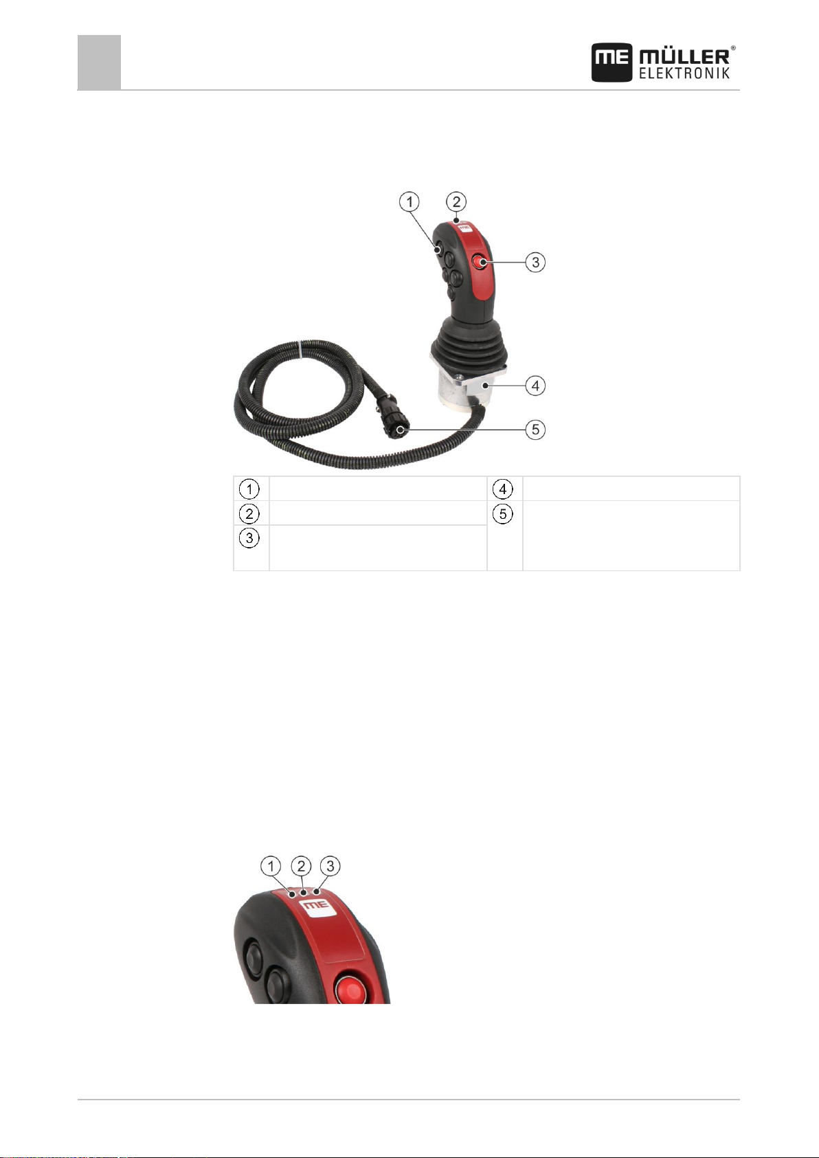
Nine buttons
Rating plate
LED lights
CPC connector for connection to
the vehicle's ISOBUS In-CabConnector
Level switch
1
1.1
1.2
Product description
Using the joystick
The ISOBUS-Joystick PRO is an ancillary operating device which can rapidly access
the functions of an ISOBUS job computer.
The joystick is fitted with nine buttons and a single level switch, which enables
switching between two levels. This enables the actuation of a total of 18 functions on
the ISOBUS job computer. The current level is indicated by an LED.
The joystick can be used to operate ISOBUS job computers which support the
Auxiliary-N protocol.
Meaning of the LED lights
The joystick has three LED lights which display the current state of the joystick.
Page 5

Product description
Information on the nameplate
1
V2.20170628
5
Green LED light
Yellow LED light
Red LED light
Light
Meaning
The connection between joystick and vehicle is active.
The joystick is connected to the terminal successfully.
The red level of the joystick is active. If this LED does not light up, the
blue level is active.
Abbreviation
Meaning
Customer number
If the product was manufactured for an agricultural
machinery manufacturer, the agricultural machinery
manufacturer's item number will be shown here.
Hardware version
Müller-Elektronik item number
Operating voltage
The product may only be connected to voltages within this
range.
Software version
Serial number
1.3
Information on the nameplate
The nameplate is located on the underside of the joystick.
Abbreviations on the rating plate
Page 6

1
Product description
EG declaration of conformity
6
3232258620-02-EN
Product name:
ME_AR Joystick AUX N Proportional m.
CPC
Item number:
3032258620
Harmonised standards applied:
EN ISO 14982:2009
(EMC Directive 2014/30/EU)
1.4
EG declaration of conformity
Herewith we declare that the product designated below, on the basis of its design
and construction in the form brought onto the market by us, is in accordance with the
relevant safety and health requirements of the EC Directive of Electromagnetic
Compatibility 2014/30/EU. If alterations are made to the product without prior
consultations with us, this declaration becomes invalid.
Page 7

Assembly instructions
2
V2.20170628
7
2
Procedure
Assembly instructions
You fit the joystick as follows:
1. Fit the joystick next to the driver on the in the vehicle cab. Use the supplied
bracket.
2. Plug the connector into the ISOBUS in-cab-connector of your vehicle.
⇨ The joystick is now connected to your vehicle.
⇨ When the vehicle is switched on, the LED on the joystick lights up.
Page 8
3
Operation
Assigning functions
8
3232258620-02-EN
Position of the switch
Level
Locked
Red – the LED lights up.
Unlocked
Blue – the LED does not light up.
3
3.1
3.2
Procedure
3.3
Procedure
Operation
Assigning functions
You assign ISOBUS job computer functions using the terminal. You can read how to
do this in the operating instructions for the terminal.
Executing functions
Each button on the joystick can be assigned with two functions. The position of level
switch determines the function which is performed when the button is pressed.
To operate the joystick:
1. Put the level switch into the desired position.
⇨ The LED lights up depending on the selected position.
2. Press the button with the desired function.
⇨ The function will be activated.
3. Release the button to exit the function.
Viewing functions
To view the functions which are assigned to the joystick:
The job computer is connected to the ISOBUS power socket.
You have assigned functions to the joystick.
1. Start the terminal.
2. Open the selection menu.
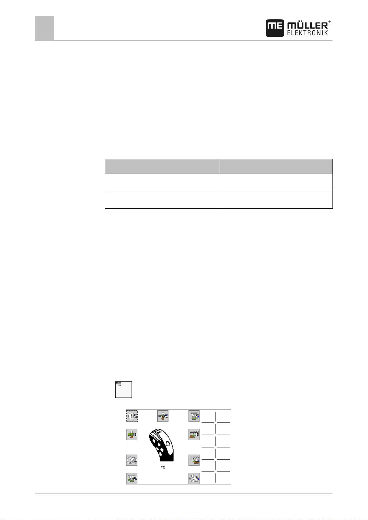
3. – Open the Joystick application.
⇨ The following screen appears:
Page 9

Operation
Viewing functions
3
V2.20170628
9
⇨ You can then see which joystick button has been assigned to an ISOBUS job
computer function. The current level is also shown on the screen.
Page 10

4
Technical specifications
Technical specifications of the joystick
10
3232258620-02-EN
Operating voltage
8 V to 32 V
Temperature range
-40°C to +85°C
Maximum current consumption
100 mA
Pin
Signal
Pin
Signal
1
12 VE
6 2
CAN_L
7
12 VE
3
CAN_L
8 4
CAN_H
9
0 VE
5
CAN_H
When it has reached the end of its service life, please dispose of this
product as electronic scrap in accordance with all applicable waste
management laws.
4
4.1
4.2
4.3
Technical specifications
Technical specifications of the joystick
Pin assignment CPC connector
Disposal
Page 11

List of accessories
5
V2.20170628
11
Item number
Designation
31322594
Y adapter cable with CPC and Sub-D connection
3032257801
CPC multiple socket to connect up to four operating devices
5
List of accessories
 Loading...