

Muller Elektronik SPRAYER-Controller Orchard/Vineyard MIDI 3.0, ECU-MIDI 3.0, ECU-MAXI 3.0 Installation And Operating Instructions Manual
Page 1

Installation and operating instructions
SPRAYER-Controller Orchard/Vineyard MIDI 3.0
Version: V1.20190404
3030383000-02-EN Read and follow these operating instructions.
Keep these operating instructions in a safe place for later
reference.
Page 2

Document
Copyright ©
Company details
Installation and operating instructions
Product: SPRAYER-Controller Orchard/Vineyard MIDI 3.0
Document number: 3030383000-02-EN
As of software version: 01.01.04.00
Original language: German
Müller-Elektronik GmbH & Co.KG
Franz-Kleine-Straße 18
33154 Salzkotten
Germany
Phone: ++49 (0) 5258 / 9834 - 0
Fax: ++49 (0) 5258 / 9834 - 90
Email: info@mueller-elektronik.de
Homepage: http://www.mueller-elektronik.de
Page 3

3030383000-02-EN
V1.20190404
3
1
For your safety
6
1.1
Basic safety instructions
6
1.2
Intended use
6
1.3
Layout and meaning of warnings
7
1.4
User requirements
7
1.5
Safety stickers on the product
7
1.6
Disposal
8
1.7
EU declaration of conformity
8
2
About these Operating Instructions
9
2.1
Who should read these instructions?
9
2.2
Directional information in these instructions
9
2.3
Layout of operating instructions
9
2.4
Layout of references
10
3
About the job computer
11
3.1
Job computer functions
11
3.2
System overview
11
3.3
Rating plate
12
4
Mounting and installation
13
4.1
Installing the job computer
13
4.1.1
Instructions for safe installation
13
4.1.2
Connecting the AMP connectors
13
4.1.3
Separating the AMP connectors
14
4.2
Connecting the job computer to the ISOBUS
14
4.3
Installing the junction box
15
4.3.1
Connecting the sensors and actuators to the junction box
15
4.3.2
Inserting the cable core into a terminal
16
4.3.3
Connecting the junction box to the job computer
16
5
Basic control principles
17
5.1
Switching on the job computer
17
5.2
Layout of work screen
17
5.2.1
Spray data area
18
5.2.2
Boom display area
20
5.2.3
Icons beside the implement image
22
5.3
Navigation in the software
23
5.4
Control units
24
6
Operating job computer on the field
25
6.1
Tank filling
25
6.2
Controlling the boom
26
Table of contents
Table of contents
Page 4

4
V1.20190404
3030383000-02-EN
6.2.1
Raising and lowering the air cushions
26
6.2.2
Lifting and lowering the boom
26
6.2.3
Folding and unfolding the boom
27
6.2.4
Extending and retracting the boom
29
6.3
Starting application
29
6.4
Regulating the application rate
30
6.4.1
Changing the application rate in manual mode
30
6.4.2
Using Automatic mode
31
6.4.3
Setting target rate
32
6.4.4
Stopping application
33
6.5
Operating sections
33
6.6
Operating the spraying area via the boom display
33
6.7
Adjusting the chassis
34
6.7.1
Adjusting the axles
34
6.7.2
Sloping the implement
35
6.8
Documenting work results
35
6.9
Switching the fans on and off
36
6.10
Switching the air compressor on and off
36
6.11
Operating the ME joystick
37
6.11.1
Preview mode for the ME Joystick
38
6.11.2
Viewing the assignment of the joystick
38
6.12
Operating additional functions
39
7
Configuring the job computer
40
7.1
Entering sprayer parameters
40
7.1.1
“Target Rate” parameter
40
7.1.2
“Product” parameter
40
7.1.3
“Working Width” parameter
40
7.1.4
“Wheel Impulses” parameter
40
7.1.5
“Minimum Pressure” parameter
40
7.1.6
“Maximum Pressure” parameter
41
7.1.7
“Sprayer off Below” parameter
41
7.1.8
“Regulation off Below” parameter
41
7.1.9
“Regulation Factor” parameter
41
7.1.10
“Tank Size” parameter
41
7.1.11
“Tank level alarm” parameter
42
7.1.12
“Impulses Main Flow” parameter
42
7.1.13
“Circulation Type” parameter
42
7.2
Configuring the control units
42
7.3
Calibrating the flow meter
43
7.3.1
Calibrating the flow meter with the tank method
43
7.3.2
Calibrating the flow meter with the nozzle method
45
7.3.3
Manually entering the number of impulses per liter for the flow meter
47
7.4
Configuring products
47
7.5
Selecting and configuring the speed sensor
47
7.5.1
Selecting the speed source
47
7.5.2
Calibrating the speed sensor with the 100m method
48
Table of contents
Page 5

3030383000-02-EN
V1.20190404
5
7.5.3
Configuring the reverse driving sensor
49
7.5.4
“Simulated Speed” function
49
7.6
Configuring the nozzles - for sprayers with pressure calculation
50
7.6.1
Nozzle assistant
50
7.6.2
Calibrate the nozzles
52
7.7
Configuring the sides and sections
53
7.7.1
Configuring the number of sides and sections
53
7.7.2
Pre-configuring the row spacings
53
7.7.3
Switching sections off permanently
54
7.7.4
System delay when switching the sections
54
“Delay on Start” parameter
55
“Delay on Stop” parameter
55
7.7.5
Changing the display of areas on the terminal
55
7.8
Entering the sprayer geometry
56
7.9
Assigning the joystick buttons
56
8
Troubleshooting
57
8.1
Alarm messages
57
8.2
Checking the software version
57
9
Technical specifications
58
9.1
Technical specifications of the job computer
58
9.2
Available languages
58
Table of contents
Page 6

6
V1.20190404
3030383000-02-EN
1
1.1
1.2
For your safety
1
Basic safety instructions
For your safety
Basic safety instructions
Be sure to always comply with the following instructions during operation:
▪ Before you leave the vehicle cab, ensure that all automatic mechanisms are deactivated or
manual mode is activated.
▪ Keep children away from the implement and the job computer.
▪ Carefully read and follow all safety instructions in this operating guide and in the machine
operating instructions.
▪ Observe all applicable regulations on accident prevention.
▪ Follow all recognised safety, industrial and medical rules as well as all road traffic laws.
▪ Use only clear water when you are testing the sprayer. Do not use a poisonous spray during the
tests or when calibrating the systems.
Servicing
Keep the system in a functional condition. To do so, follow these instructions:
▪ Do not make any unauthorized modifications to the product. Unauthorized modifications or use
may impair safety and reduce the service life or operability of the unit. Modifications are
considered unauthorized if they are not described in the product documentation.
▪ Never remove any safety mechanisms or stickers from the product.
▪ Before charging the tractor battery, always disconnect the tractor from the job computer.
▪ Before performing any welding on the tractor or the implement, always disconnect the power
supply to the job computer.
▪ The job computer and the cabling must not be repaired. Unauthorised attempts at repairs can fail
and cause hazardous malfunctions.
Operation
▪ Use only original accessories as spare parts.
Intended use
The product is only intended for use in the agricultural sector. The manufacturer is not liable for any
other installation or use of the product.
The manufacturer cannot be held liable for any personal injury or property damage resulting from
such non-compliance. All risk arising from improper use lies with the user.
Intended use also includes compliance with the conditions for operation and repairs prescribed by the
manufacturer.
All applicable accident prevention regulations and all other generally recognized safety, industrial,
and medical standards as well as all road traffic laws must be observed. Any unauthorized
modifications made to the equipment will void the manufacturer's warranty.
Page 7
3030383000-02-EN
V1.20190404
7
WARNING
This signal word identifies medium-risk hazards, which could potentially cause death or serious
physical injury, if not avoided.
CAUTION
damage to property, if not avoided.
NOTICE
This signal word identifies hazards that could potentially cause damage to property, if not avoided.
1.3
Example
1.4
1.5
For your safety
Layout and meaning of warnings
1
Layout and meaning of warnings
All safety instructions found in these Operating Instructions are composed in accordance with the
following pattern:
This signal word identifies hazards that could potentially cause minor or moderate physical injury or
There are some actions that need to be performed in several steps. If there is a risk involved in
carrying out any of these steps, a safety warning appears in the instructions themselves.
Safety instructions always directly precede the step involving risk and can be identified by their bold
font type and a signal word.
1. NOTICE! This is a notice. It warns that there is a risk involved in the next step.
2. Step involving risk.
User requirements
▪ Learn to operate the product in accordance with the instructions. Nobody must operate the
product before reading these instructions.
▪ Please read and carefully observe all safety instructions and warnings contained in these
Operating Instructions and in the manuals of any connected vehicles and farm equipment.
▪ If there is anything within these instructions that you do not understand, please do not hesitate to
contact us or your dealer. Müller-Elektronik's Customer Services department will be happy to
assist you.
Safety stickers on the product
Sticker on the job computer
Do not clean with a high-pressure cleaner.
Page 8

8
V1.20190404
3030383000-02-EN
(EMC Directive 2014/30/EU)
In conformity with further EU directives:
Directive 2011/65/EU (RoHS 2)
1.6
1.7
For your safety
1
Disposal
When it has reached the end of its service life, please dispose of this product as
electronic scrap in accordance with all applicable waste management laws.
EU declaration of conformity
Herewith we declare that the design and construction of this product and its identical variants, as well
as the form brought onto the market by us, is in accordance with the relevant safety and health
requirements of the EU Directive of Electromagnetic Compatibility 2014/30/EU. If alterations are
made to the product without prior consultations with us, this declaration becomes invalid.
Disposal
MIDI 3.0 job computer
Harmonised standards applied: EN ISO 14982:2009
Page 9

3030383000-02-EN
V1.20190404
9
Type of depiction
Meaning
2.
⇨
This will happen when you perform an action.
⇨
steps.
can be performed.
2
2.1
2.2
2.3
About these Operating Instructions
About these Operating Instructions
Who should read these instructions?
2
Who should read these instructions?
These instructions are intended for operators of orchard or vineyard sprayers equipped with a job
computer from Müller-Elektronik.
The instructions will show you:
▪ The meaning of the icons on the screen;
▪ Where to find the settings that are relevant for a function in the application;
▪ How to configure the application;
▪ How to calibrate components that need to be calibrated.
The instructions do not explain how to operate the orchard or vineyard sprayer. It is not a substitute
for the orchard/vineyard sprayer manufacturer's instruction manual.
Directional information in these instructions
All directional information in these instructions, such as “left”, “right”, “forward”, “back”, is relative to
the movement direction of the vehicle.
Layout of operating instructions
The operating instructions explain step by step how you can perform certain operations with the
product.
We use the following symbols throughout these Operating Instructions to identify different operating
instructions:
1.
Actions that must be performed in succession.
Result of the action.
Result of an operating instruction.
This will happen when you have completed all
Requirements.
In the event that any requirements have been
specified, these must be met before an action
Page 10

10
V1.20190404
3030383000-02-EN
2.4
About these Operating Instructions
2
Layout of references
Layout of references
If any references are given in these Operating Instructions, they appear as:
Example of a reference: [➙ 10]
References can be identified by their square brackets and an arrow. The number following the arrow
shows you on what page the section starts where you can find further information.
Page 11
3030383000-02-EN
V1.20190404
11
3
3.1
3.2
About the job computer
About the job computer
Job computer functions
3
Job computer functions
The SPRAYER-Controller Orchard/Vineyard MIDI 3.0 job computer is an ISOBUS job computer that
can control the operation of orchard or vineyard sprayers.
The ISOBUS job computer is the switching central of the orchard or vineyard sprayer. Several
sensors are connected to the job computer, which monitor important implement parts. The job
computer controls the implement based on these signals and on the operator's specifications. An
ISOBUS terminal serves as an interface. All implement-specific data is stored in the job computer and
is therefore maintained even when changing the terminal.
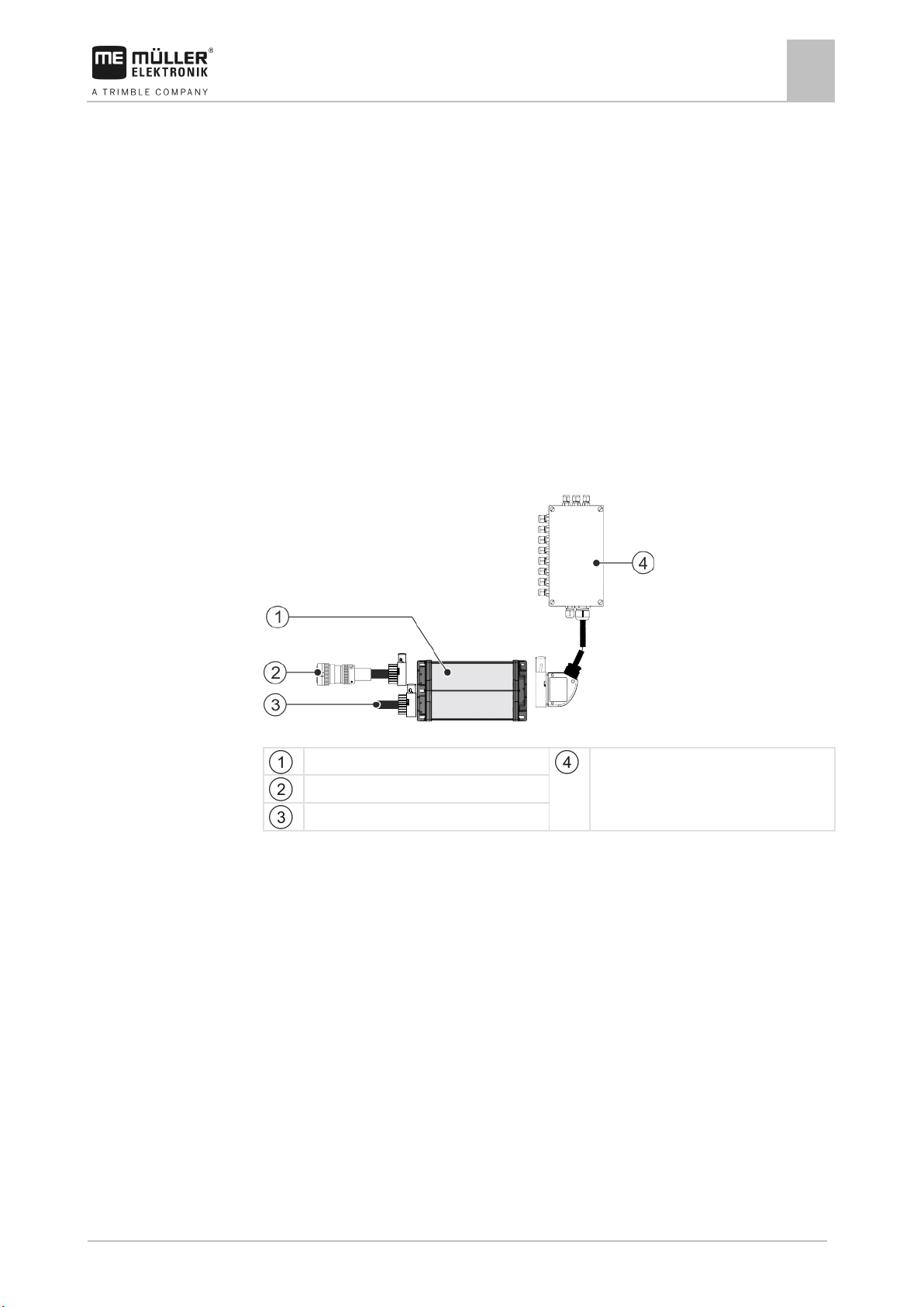
System overview
The system consists of one or several job computers that are mounted on the orchard or vineyard
sprayer and control the operation.
Small system with one job computer
ECU-Midi job computer
ISOBUS cable
CAN termination
Junction box
Page 12
12
V1.20190404
3030383000-02-EN
ECU-MIDI slave job computer
Abbreviation
Meaning
will be shown here.
Hardware version
Müller-Elektronik item number
The product may only be connected to voltages within this range.
Software version upon delivery
Serial number
3.3
About the job computer
3
Rating plate
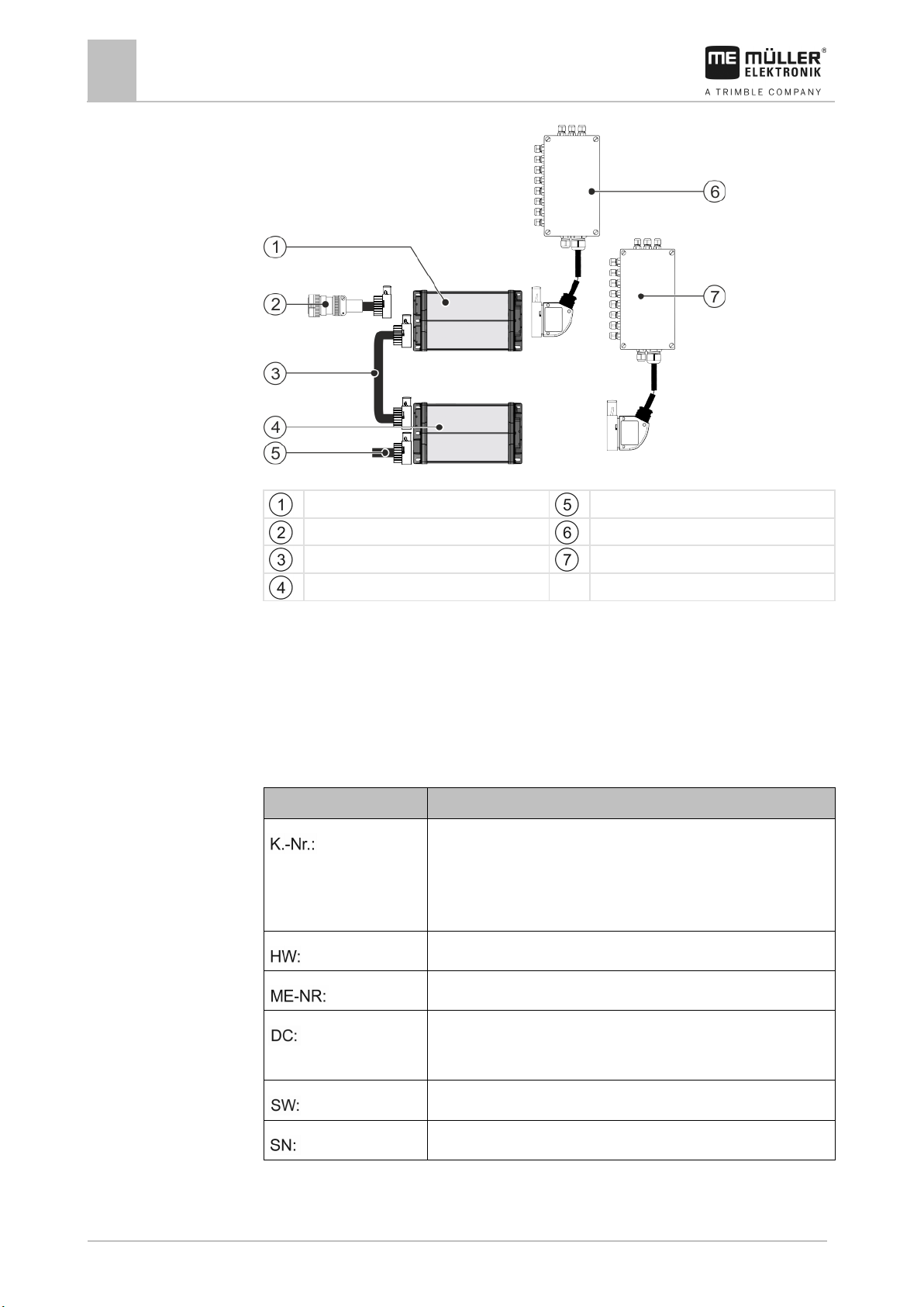
Large system with two job computers
ECU-MIDI master job computer
CAN termination
ISOBUS cable
Connecting cable between the job computers
Master junction box
Slave junction box
Each job computer is responsible for controlling selected functions of the orchard or vineyard sprayer
and receives signals from selected sensors. For systems with two or more job computers, each uses
identical job computers and junction boxes.
Rating plate
Abbreviations on the rating plate
Customer number
If the product was manufactured for an agricultural machinery
manufacturer, the agricultural machinery manufacturer's item number
Operating voltage
Page 13
3030383000-02-EN
V1.20190404
13
4
4.1
4.1.1
4.1.2
Procedure
Mounting and installation
Mounting and installation
Installing the job computer
4
Installing the job computer
Instructions for safe installation
To prevent damage to the system components, consider the following during installation:
▪ Install the job computer where it is protected from dirt. You therefore avoid unintentional cleaning
of the job computer by the implement operator using a high-pressure cleaner.
▪ In the installed position, the connectors and the pressure compensation membrane must be
facing to the side.
▪ Fasten the job computer with four fixing bolts and a flat washer (lock washers can cause cracks
in the plastic on the long term) on a conducting spot on the implement chassis. In case of
improper installation, the ESD discharges can cause malfunctions.
▪ All of the sockets and connectors that are not used must be protected from dust and water using
suitable dummy connectors.
▪ All of the connectors must be tightly sealed. This makes them waterproof.
▪ Do not use the system if some of its parts are damaged. Damaged parts can cause malfunctions
and lead to injuries. Replace damaged components or repair them if possible.
▪ Use only original components manufactured by Müller-Elektronik.
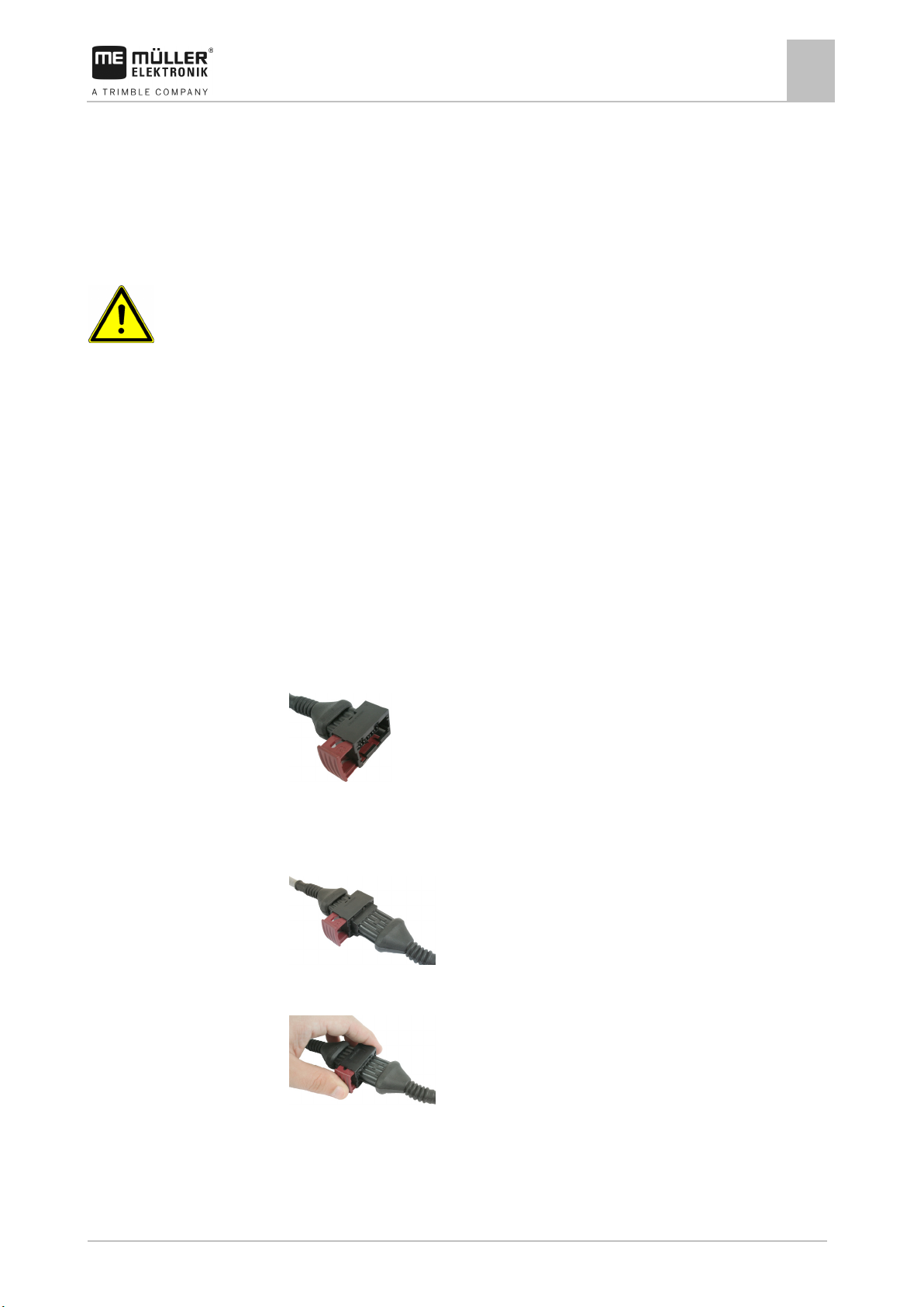
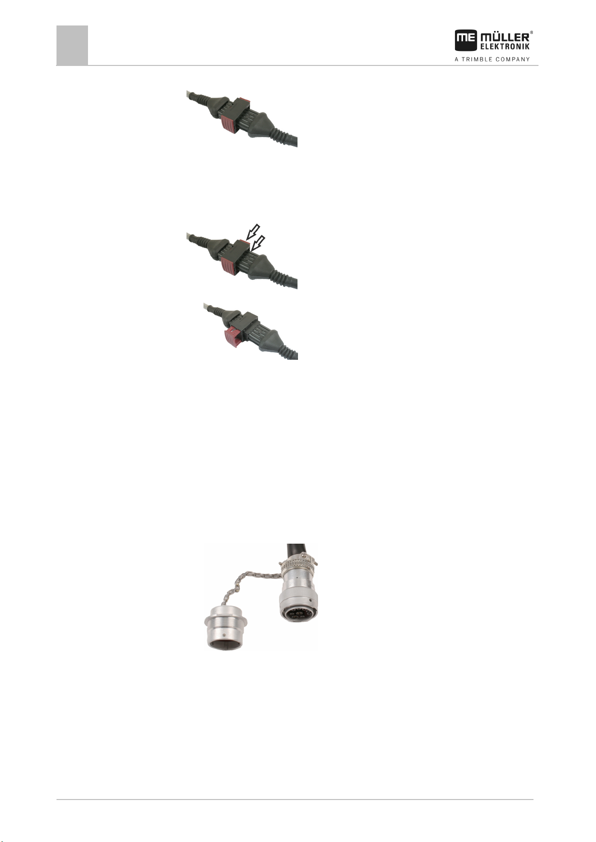
Connecting the AMP connectors
This is how to connect two AMP connectors:
1. Pull out the red locking device of the AMP socket all the way to the end.
⇨ You will hear a loud clicking sound.
⇨ The openings for inserting the locking pins of the connector are visible.
2. Insert the connector into the socket. It should be possible to easily insert the locking pins in the
openings.
⇨ The connector is loosely inserted in the socket.
3. Press in the red locking device.
⇨ You will hear a loud clicking sound.
⇨ A part of the locking device comes through to the other side of the socket.
Page 14
14
V1.20190404
3030383000-02-EN
4.1.3
Procedure
4.2
Procedure
Mounting and installation
4
Connecting the job computer to the ISOBUS
⇨ You have connected and locked the connector with the socket.
Separating the AMP connectors
This is how to separate two AMP connectors:
1. Press in both ends of the red locking device in direction of the connector.
⇨ You will hear a loud clicking sound.
⇨ The locking device has been released.
2. Pull out the red locking device of the AMP socket all the way to the end.
3. Pull the connector out of the socket.
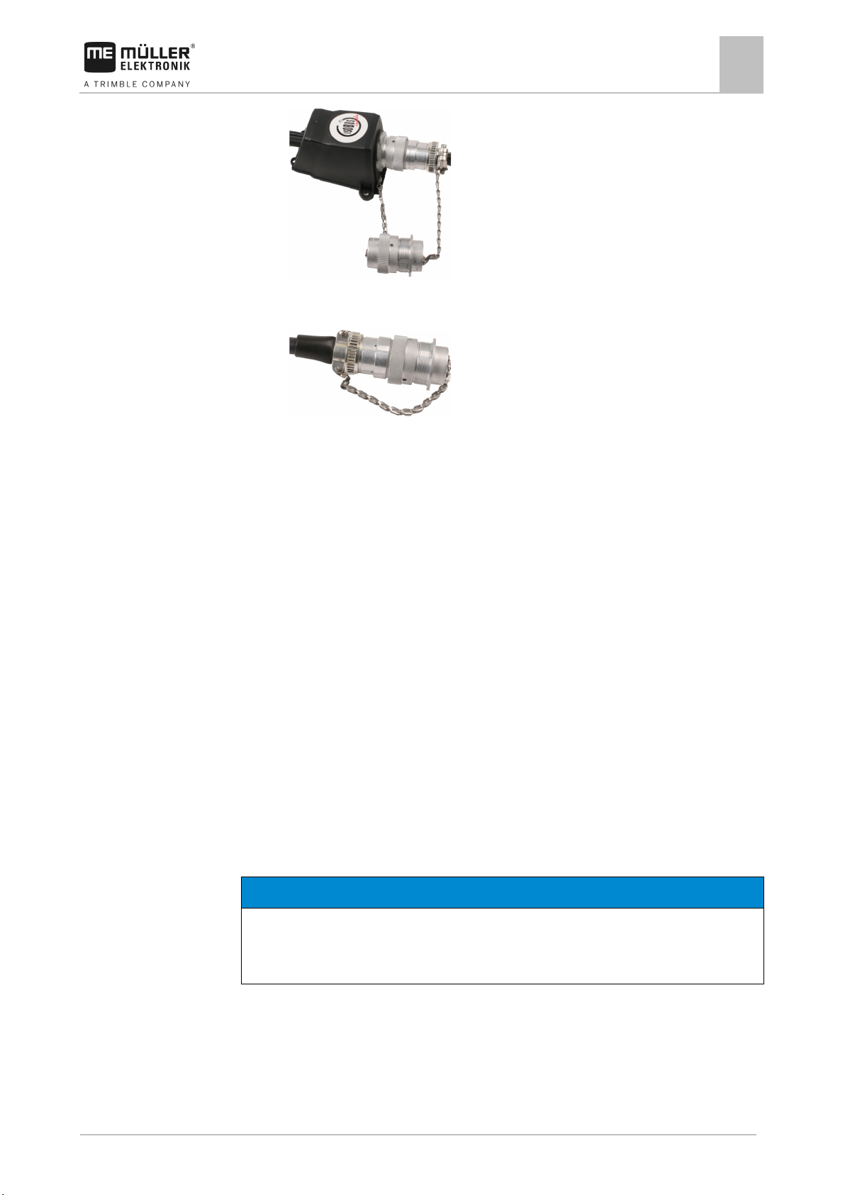
Connecting the job computer to the ISOBUS
To connect the job computer to the power supply and to the ISOBUS terminal, you have to connect
the ISOBUS cable to an ISOBUS power socket on the tractor.
This is how to connect the job computer to the ISOBUS:
1. Take the ISOBUS cable from the job computer.
2. Unscrew the dust protection cap.
⇨
3. Insert the ISOBUS connector into the ISOBUS power socket on the tractor.
4. Lock the connector. For basic vehicle harnesses from Müller-Elektronik, turn the connector
clockwise. For other ISOBUS basic vehicle harnesses, the procedure depends on the model.
⇨ The connector fits tightly.
5. Screw the dust protection cap of the connector and the socket together.
Page 15
3030383000-02-EN
V1.20190404
15
NOTICE
Risk of short-circuit
◦ Pay attention to the polarity of the cable cores and the terminals.
4.3
4.3.1
Procedure
Mounting and installation
Installing the junction box
4
⇨
6. When the work is completed, separate the connection and screw the dust protection cap back
on.
⇨
Installing the junction box
Take note of the following when selecting the installation location:
▪ Ensure that cables cannot be damaged by the moving implement.
▪ The cable glands must be facing downwards.
Connecting the sensors and actuators to the junction box
Every sensor and every actuator that is mentioned in the pin-out diagram must be connected to the
junction box mentioned in the pin-out diagram.
This can be done in two ways:
▪ The sensor or actuator ends with a short cable and an AMP connector.
In this case, you will receive a fitting extension cable for each sensor. You must insert the
extension cable in the junction box and connect it to the fitting terminal.
▪ The sensor or actuator ends with a long cable without a connector. You have to insert it in the
junction box and connect it to the fitting terminal.
The terminal to which you must connect the cable core depends on the respective implement and on
the type of sensor or actuator.
Please note that the cable cores for the ultrasonic sensor trigger always need to be connected to Pins
2 and 3.
When exchanging the polarity of cable cores, machine sensors can be damaged by a short-circuit.
The junction box is not powered.
There is no voltage on the components to be connected.
1. Remove the cable coating so that all cable cores are exposed.
Page 16

16
V1.20190404
3030383000-02-EN
4.3.2
Procedure
4.3.3
Procedure
Mounting and installation
4
Installing the junction box
2. Insert the cable to the end of the coat. There should only be cable cores inside the junction box.
The cable coating must end at the junction box casing. This is the only way to ensure that you
have enough space in the junction box to be able to guide all of the cable cores to the terminals.
3. Remove the cable coating of the cable cores ca. 1 cm from the end of the cable core.
4. CAUTION! Pay attention to the proper polarity of the cable cores and the terminals.
5. Connect the cable cores to the terminals.
To do so, use the information on the lid of the junction box, on the relay circuit board and in the
pin-out diagram.
6. With screw terminals, use wire end sleeves. Wire end sleeves may not be used with spring-
loaded terminal blocks.
7. Close the screw connections of the junction box.
After screwing them shut, the glands should be sealed.
8. Close unused openings in the casing of the junction box with blind caps.
Inserting the cable core into a terminal
Each terminal consists of two openings:
▪ The upper opening of the terminal opens the lower opening.
▪ The bottom opening of the terminal serves to insert and clamp one cable core.
You have prepared a small flat screwdriver that fits the upper opening of the terminal. You only
need this screwdriver if there are no wire end sleeves on the cable cores.
You have cut the cable to the proper length and have exposed the cable cores according to the
instructions, or you have a finished cable from Müller Elektronik.
The tractor engine is switched off.
The junction box is not powered.
There is no voltage on the components to be connected.
1. Find the proper connectors for the cable cores to be connected.
To do so, use the information on the lid of the junction box, on the relay circuit board and in the
pin-out diagram.
2. Insert the cable core into the opening in the lower part of the terminal. If you are not using wire
end sleeves, you first have to use the screwdriver.
⇨ The cable core will be held by the terminal.
⇨ You have clamped the cable core.
Connecting the junction box to the job computer
1. Connect the AMP connector of the junction box onto the proper job computer.
Page 17
3030383000-02-EN
V1.20190404
17
implement image
5
5.1
Procedure
5.2
Basic control principles
Basic control principles
Switching on the job computer
5
Switching on the job computer
1. Connect the ISOBUS cable of the job computer to the ISOBUS connector on the tractor.
2. Start the ISOBUS terminal.
⇨ The job computer is started together with the terminal.
⇨ When starting up for the first time, the job computer initially has to transmit lots of
information to the terminal. This can take a few minutes.
⇨ When all of the data from the job computer application has been loaded, their icon appears
on the terminal:
.
3. Open the job computer application. To do so, follow the instruction for the ISOBUS terminal.
⇨ The work screen of the job computer appears.
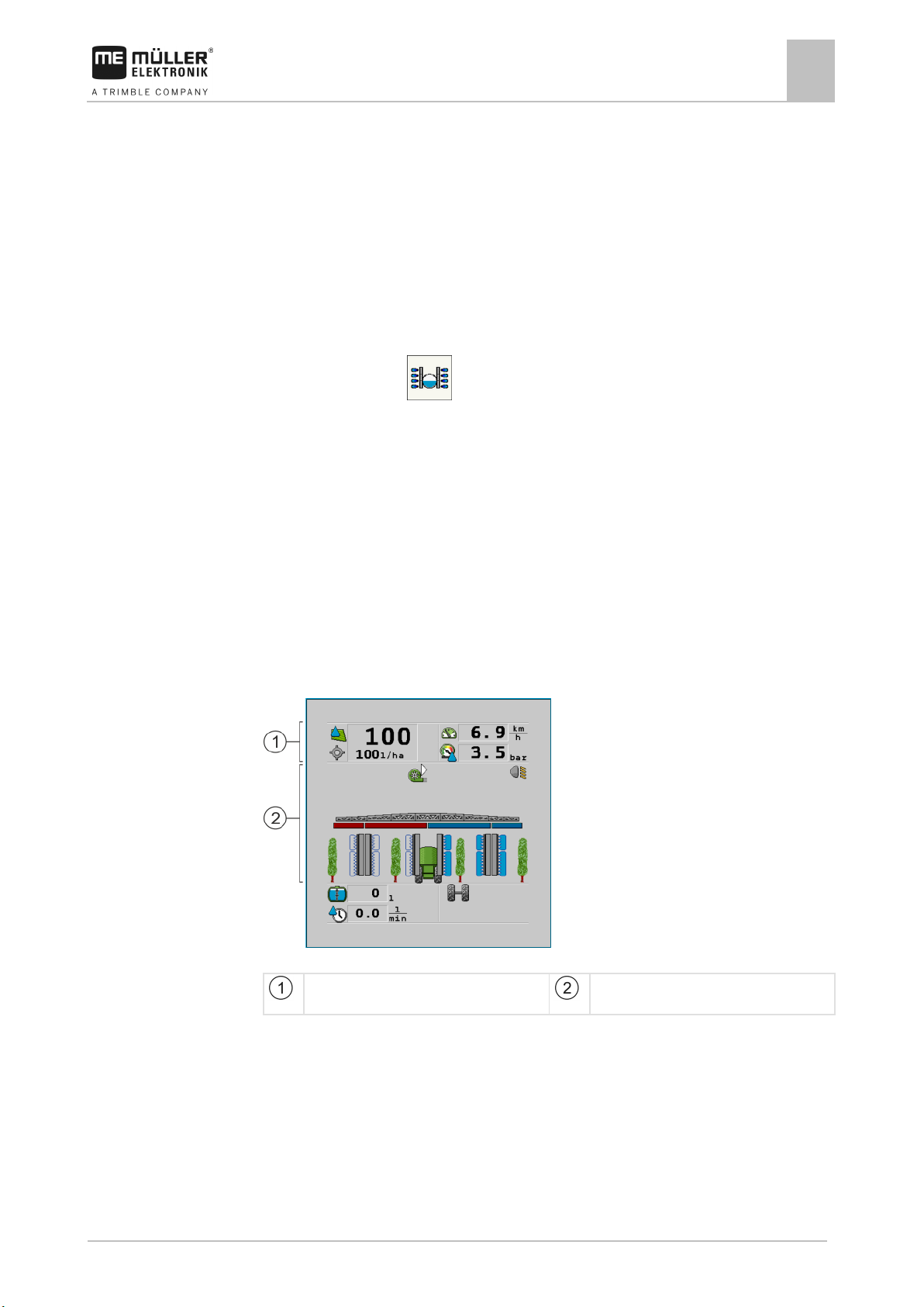
Layout of work screen
The work screen is always shown during operation and informs you of the status of the orchard or
vineyard sprayer.
The work screen is divided into several areas. In each area, information on specific topics may
appear.
When configuring the job computer, the areas can be changed for a orchard or vineyard sprayer
model from a specific manufacturer. For this reason, the following graphs only show the standard
version of the overview.
Areas on the work screen
“Spray data” area
“Boom display” area with icons beside the
You can read about the information that appears in these areas in the following sections.
Function icons appear beside the work screen, which perform functions when they are tapped. Their
position and operation depend on the type of ISOBUS terminal.
In the table below, you can see the meaning of the function icons on the work screen.
Page 18

18
V1.20190404
3030383000-02-EN
Function icon
Function
/
Icon
Meaning
The current value (current application rate) appears next to it.
- Speed slower than “Sprayer off below” [➙ 41]
5.2.1
Icons
Basic control principles
5
Layout of work screen
Opens the “Results” screen.
Opens the “Parameters” screen.
Opens the “Tank Filling” screen.
Opens the “Folding” screen.
Switches between manual and automatic regulation of the application rate.
Opens a screen with additional functions.
Activates or deactivates operation of the spraying areas.
Opens the “ME-Joystick” screen.
Switches between two levels of icons.
Shows the next page with function icons.
Spray data area
The following information is shown in this area:
Selected icons in the spray data area
Depending on the configuration, the following icons may appear:
The application rate will be automatically regulated.
No flow. The main valve cannot be opened because one of the
requirements has not been fulfilled:
Page 19

3030383000-02-EN
V1.20190404
19
Icon
Meaning
- SECTION-Control has terminated the application
See: Using Automatic mode [➙ 31]
See: Changing the application rate in manual mode [➙ 30]
parameter and higher than “Sprayer off below” [➙ 41]
area that should not be sprayed.
See: Documenting work results [➙ 35]
been interrupted because the speed is too low.
The icon can only appear if the signal source was automatically selected.
Basic control principles
Layout of work screen
5
- Section status
- Target rate out of reach
The application rate will be automatically regulated.
The target rate appears next to it.
The application rate will be manually regulated.
The bar graph only appears when the target rate is changed in automatic
mode using the +10% and -10% buttons. It shows the deviation from the
original target rate.
Automatic mode is deactivated. The flow will not be regulated.
The current speed is lower than the “Regulation off below” [➙ 41]
The target rate is defined by an external source: Task Controller,
prescription map, external sensor etc. See: Setting target rate [➙ 32]
- A problem has occurred with the transmission of the target rate from an
external source.
- The sprayer is outside of the area defined in the prescription map or in an
The sprayer functions will be switched on and off through an “S-Box”.
Trip counter is deactivated
Speed
If the numbers are red, it means that the regulation or the application have
The speed signal from the tractor / ISOBUS cannot be adopted. The system
/
(background is
flashing)
will now determine the speed using the sensor connected to the junction
box.
Ensure that the number of impulses per 100m is correctly entered.
The vehicle is driving in reverse.
Page 20

20
V1.20190404
3030383000-02-EN
Icon
Meaning
5.2.2
Illustration
Basic control principles
5
Layout of work screen
Simulated speed activated. [➙ 49]
Pressure
Boom display area
In the boom display you find the following information:
▪ Number of sections
▪ Which sections are preselected or switched off
▪ Which sections are applying
The diagrams below show how the sections may appear in the boom display area:
Sections 1 and 2 are closed and deactivated.
Sections 1 and 2 are closed. All of the other sections are open and spraying.
When SECTION-Control is activated, the blue-red SECTION-Control icon also appears.
Page 21

3030383000-02-EN
V1.20190404
21
Picture
Status of the section valve
Status of the control/main valve
TION-Control
valve
stick
Basic control principles
Layout of work screen
5
When SECTION-Control is not possible, this icon is red.
Each rectangle corresponds to a section valve.
Section status
Closed valve Closed valve
Open valve Closed valve
Open valve Open valve
Closed valve Open valve
The section is permanently deactivated
When the sections are automatically switched using SECTION-Control, you have to ensure that the
sections are not deactivated using an S-Box or a joystick. In this case, the section would be marked
with a red cross and remain closed.
Section status with SECTION-Control and with S-Box
Picture Status defined by SEC-
Status of the control/main
Status via S-Box or joy-
Open valve Open valve Closed valve
Open / closed valve Closed valve Closed valve
Page 22

22
V1.20190404
3030383000-02-EN
Icon
Meaning
Other causes are also possible.
operated.
5.2.3
Basic control principles
5
Layout of work screen
Icons beside the implement image
Functions
Sections are switched via SECTION-Control.
The SECTION-Control application has closed all sections.
Examples for the cause:
▪ The sprayer is outside of the field boundary or in an area that has
already been worked
▪ Sprayer on the headland
Beacon is switched on.
The working lights are switched on.
Left fan switched on.
Middle fan switched on.
Right fan switched on.
Air compressor switched off.
Air compressor switched on.
Boom height sensor activated.
If a boom height sensor is activated, the air cushions and fans cannot be
The oil level is too low.
The chassis settings are activated.
Sliding axle is being extended.
Page 23

3030383000-02-EN
V1.20190404
23
Icon
Meaning
Icon
Meaning
Function icon
Meaning
Pressed long: Scrolls back to the previous screen.
5.3
Controls
Basic control principles
Navigation in the software
5
Sliding axle is being retracted.
The implement is being sloped to the left.
The implement is being sloped to the right.
Currently selected product.
Output in litres per minute
Area output per hour
Tank fill level
Navigation in the software
Depending on the equipment of the sprayer and the scope of its functions, it is possible that not all of
the executable functions are shown on one page of the screen.
If there are other functions that can be executed, one of the following function buttons always
Counters
appears:
Use the following function keys to operate the function:
Scrolls between several pages.
Scrolls back to the previous screen.
Pressed briefly: Scrolls to the next page.
Page 24

24
V1.20190404
3030383000-02-EN
5.4
Basic control principles
5
Control units
Control units
The following options are available for operating the job computer:
▪ Using the function buttons on the screen
▪ Using AUX-N operating devices
▪ Using the ME joystick
▪ Using the ME S-Box
▪ Using an external keypad
You can find more information on the configuration and operation in the following sections:
▪ Configuring the control units [➙ 42]
▪ Operating the ME joystick [➙ 37]
▪ Viewing the assignment of the joystick [➙ 38]
▪ Preview mode for the ME Joystick [➙ 38]
Page 25

3030383000-02-EN
V1.20190404
25
Function icon
Function
6
6.1
Procedure
Operating job computer on the field
Operating job computer on the field
Tank filling
6
Tank filling
You must enter the new content of the tank manually.
Tank was fully filled up.
Set tank content to 0 liter.
To enter the new tank content when you have completely refilled the spray liquid tank:
1. Switch to the “Filling - manual ” screen:
⇨ The following screen appears:
2.
- Enter full tank
or
3. In the “New tank content ” box, enter the tank content after refilling.
⇨ The new tank content appears in the work screen, in the tank data area.
If you are using TANK-Control, it will show the current tank content. Automatic tank filling via TANKControl is currently not possible.
Page 26

26
V1.20190404
3030383000-02-EN
WARNING
Injury to persons through improper operation
◦ Learn the sequence in which your orchard or vineyard sprayer must be operated safely.
Function icon
Function
6.2
6.2.1
Path
Illustration
6.2.2
Path
Operating job computer on the field
6
Controlling the boom
Controlling the boom
Every orchard or vineyard sprayer is designed differently and must be operated differently. In this
section, only the icons that appear on the screen of the terminal can be explained.
◦ Read the orchard or vineyard sprayer operating instructions.
Raising and lowering the air cushions
This function raises or lowers the air cushions of the orchard or vineyard sprayer.
This is how you reach the screen with this function:
Use the following function keys to operate the function:
Raises the air cushions.
Lowers the air cushions.
The air cushions are being raised. The arrows indicate the direction.
The air cushions are being lowered. The arrows indicate the direction.
Lifting and lowering the boom
This is how you reach the screen with this function:
To operate this function the user needs the ME joystick first of all.
Use the following function keys to operate the function:
Page 27

3030383000-02-EN
V1.20190404
27
Function icon
Function
Boom part: Middle left
Boom part: Outer right
Illustration
6.2.3
Path
Illustration
Operating job computer on the field
Controlling the boom
6
Lifts the boom.
Lowers the boom.
The boom is being raised. The arrow indicates the direction.
The boom is being lowered. The arrow indicates the direction.
Folding and unfolding the boom
This function folds and unfolds the orchard or vineyard sprayer boom.
Operation depends on the following factors:
▪ Number of boom parts that can be folded in and out.
▪ Type of orchard or vineyard sprayer.
This is how you reach the screen with this function:
Structure of a boom
The following diagram shows the structure of booms and what the individual boom parts are called.
The diagram shows an orchard or vineyard sprayer with a seven-part boom, but it also applies to
smaller booms.
Parts of the boom on an orchard or vineyard sprayer
Three-part boom
Five-part boom
Seven-part boom
Boom part: Outer left
Boom part: Inner left
Boom part: Unmoving part
Boom part: Inner right
Boom part: Middle right
Page 28

28
V1.20190404
3030383000-02-EN
The arrows appear for folding boom sections and indicate the direction of movement.
Arrow pointing outwards means: Fold out
Function
Three-section boom
Five-section boom
Seven-section boom
symmetrically
symmetrically
middle symmetrically
middle symmetrically
Function icons
Operating job computer on the field
6
Controlling the boom
Representation of the boom on the “Boom folding” screen
Folding parts of the boom
Icon: Boom section is being folded in or out
On the following diagram, you see how a seven-part boom is shown on the function icons.
Directional arrow
Arrow pointing inwards means: Fold in
Sections of the boom marked in grey are not folded in or out with this function icon
Sections of the boom marked in white are folded in or out with this function icon
Use the following function keys to operate the function:
Fold inner boom
Unfold inner boom
Fold boom in the
Unfold boom in the
Unfold outer left boom
Unfold outer right boom
Page 29

3030383000-02-EN
V1.20190404
29
Function
Three-section boom
Five-section boom
Seven-section boom
boom symmetrically
boom symmetrically
Function icon
Function
6.2.4
Path
Illustration
6.3
Procedure
Operating job computer on the field
Starting application
6
Fold inner and middle
Unfold inner and middle
Extending and retracting the boom
This function extends and retracts the orchard or vineyard sprayer boom.
This is how you reach the screen with this function:
Use the following function keys to operate the function:
Retracts the boom symmetrically.
Extends the boom symmetrically.
Extends the boom on the left.
Extends the boom on the right.
Retracts the boom on the left.
Retracts the boom on the right.
The boom is retracted symmetrically. The arrows indicate the direction.
The boom is extended symmetrically. The arrows indicate the direction.
Starting application
To start the application:
The tractor with the sprayer is on the field.
You have configured the job computer.
You have folded out the boom.
1. Ensure that all prerequisites have been fulfilled.
Page 30

30
V1.20190404
3030383000-02-EN
Function icon
Function
6.4
6.4.1
Operating job computer on the field
6
Regulating the application rate
2. - Start application
⇨ In manual mode:
The sprayer starts the application.
⇨ In automatic mode:
The sprayer is ready for application.
As long as the sprayer is not moving, the following icon appears on the work screen,
depending on the “Sprayer off below” parameter:
3. If you are in automatic mode, start driving and exceed the minimum speed for automatic
regulation (parameter: “Regulation off below”).
⇨ As long as the sprayer is not regulating, the following icon appears on the work screen,
depending on the “Regulation off below” parameter:
⇨ As soon as the minimum speed is exceeded, the sprayer will begin regulating.
⇨ You have started application.
Regulating the application rate
Depending on the sprayer equipment, the application rate regulation system can control the opening
of the control valve.
Work modes
You can regulate the application rate manually or you can leave the regulation to the job computer:
▪ In manual mode, you can control the opening of the control valve with two buttons.
▪ In automatic mode, the job computer regulates the degree of opening of the control valve such
that the target rate defined for the application rate is reached.
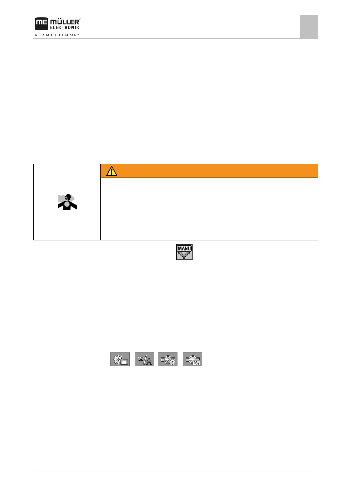
Use the following function keys to operate the function:
Switches the mode between manual and automatic.
You will learn how to operate the system in the following sections.
Changing the application rate in manual mode
When the field sprayer is in manual mode, the application is not regulated according to a specified
rate. The application rate must be set manually instead.
The application rate must be regulated manually when the following icon appears in the spray data
area of the work screen:
Application in manual mode
Please note that the pressure is also automatically changed when you change the application rate.
Page 31

3030383000-02-EN
V1.20190404
31
Function icon
Function
work screen
last known position until the speed changes.
The main valve is closed automatically.
SECTION-Control app.
6.4.2
Requirements
Mode of operation
Operating job computer on the field
Regulating the application rate
6
To operate this function the user needs the ME joystick first of all.
Use the following function keys to operate the function:
Increases the application rate.
Reduces the application rate.
Using Automatic mode
In automatic mode, the job computer regulates the degree of opening of the control valve and the
main valve on the manifold such that the target rate defined for the application rate can be reached.
You are in automatic mode when one of the following icons appears in the spray data area of the
work screen:
Icon on the
Meaning
Sprayer can apply.
The speed of the sprayer is lower than “Regulation off below”
Sprayer can apply. The flow will not be regulated. The control valve remains in the
The speed of the sprayer is lower than “Sprayer off below”
Regulation is not possible because the application was deactivated by the
To use automatic mode, the following conditions must be fulfilled:
▪ Target rate has been entered.
▪ Flow meter is calibrated.
▪ A speed signal is available.
▪ Working width is set.
▪ The parameter “Regul. factor” has been set.
In the following cases, the flow is automatically adjusted:
▪ Speed of the sprayer has changed.
▪ Number of switched-on sections has changed.
▪ You have changed the target rate manually.
▪ The application rate has been changed by the information from the application map.
The speed and precision of the regulation depends on the value of the “Regul. factor” parameter.
You can change the target rate manually while driving in Automatic mode.
To operate this function the user needs the ME joystick first of all.
Page 32

32
V1.20190404
3030383000-02-EN
Function icon
Function
Procedure
6.4.3
Methods
Illustration
Operating job computer on the field
6
Regulating the application rate
Increases the target rate by 10%.
Reduces the target rate by 10%.
Restores the target rate back to 100%.
To change the target rate during work:
1.
2.
- Activate automatic steering.
- Open main valve.
⇨ Spray cones appear under the boom icon on the work screen. Still, the sprayer is not
spraying.
⇨ As long as you are at a standstill, the sprayer cannot start spraying. See icons:
and
3. Exceed the speed defined in the “Regulation off below” parameter.
⇨ The sprayer begins adjusting the application rate to the defined target rate.
4.
or - Press to change the target rate.
⇨ The degree of change appears on the work screen.
5.
- Restores the original target rate.
Setting target rate
The target rate is the quantity of spray liquid you want to apply per hectare.
The job computer will attempt to maintain this rate during the work.
There are several ways to specify the rate:
▪ Enter rate on the “Parameters” screen. [➙ 40]
▪ The target rate can be adopted from external sources using the “ISOBUS-TC” app:
– from tasks,
– from prescription maps,
– from external sensors.
Target rate from parameters
Target rate from an external source
Page 33

3030383000-02-EN
V1.20190404
33
Function icon
Function
opened from the left.
opened from the right.
6.4.4
6.5
6.6
Procedure
Operating job computer on the field
Operating sections
6
Target rates from external data sources have a higher priority than the target rate entered in the job
computer. For this reason, you do not have to adjust the “Rate” parameter when you are working with
prescription maps.
Stopping application
You can stop application in the following ways:
▪
▪
▪ Drive slower than the set minimum speed (only in automatic mode).
- Close main valve.
or - Close the section valves consecutively.
Operating sections
To operate this function the user needs the ME joystick first of all.
Use the following function keys to operate the function:
Closes section valves from left to right.
Closes section valves from right to left.
Opens section valves from left to right.
or
When all of the section valves are closed, then the first section valve is
Closes section valves from right to left.
or
When all of the section valves are closed, then the first section valve is
Operating the spraying area via the boom display
You can directly operate the spraying areas via the boom display.
To operate the spraying area during operation:
1.
- Activate operation of the spraying areas.
⇨ The boom display changes as follows:
2. Press on the desired spraying areas to activate/deactivate them.
Page 34

34
V1.20190404
3030383000-02-EN
Function icon
Meaning
Icon
Meaning
6.7
6.7.1
Path
Operating job computer on the field
6
Adjusting the chassis
⇨ The boom display changes as follows:
3.
- Activate operation for multiple spraying areas (groups) simultaneously.
⇨ The boom display changes as follows:
4. Press on the desired spraying area to activate/deactivate it.
⇨ The boom display changes as follows:
5.
Adjusting the chassis
- Terminate operation of the spraying areas.
Adjusting the axles
You can adjust the axles of the orchard or vineyard sprayer hydraulically during operation.
This is how you reach the screen with this function:
Use the following function keys to operate the function:
If you are using a sliding axle, you must press and hold the function button to extend or retract the
sliding axle.
Extends the sliding axle. The track width will be increased.
Retracts the sliding axle. The track width will be reduced.
The following icons may appear on the screen:
The sliding axle is being extended.
Page 35

3030383000-02-EN
V1.20190404
35
Icon
Meaning
Function icon
Meaning
Icon
Meaning
Function icon
Function
6.7.2
Path
6.8
Operating job computer on the field
Documenting work results
6
The sliding axle is being retracted.
Sloping the implement
You can slope the orchard or vineyard sprayer hydraulically during operation.
This is how you reach the screen with this function:
Use the following function keys to operate the function:
Slopes the implement to the left.
Slopes the implement to the right.
The following icons may appear on the screen:
The implement is being sloped to the left.
The implement is being sloped to the right.
Documenting work results
You can document your work in the “Counters” screen.
On the “Counters” screen, there are two types of counter:
▪ Trip counter – documents the work until it is deleted.
▪ Total counter – documents the work since initial start-up.
The “Counters” screen has the following information:
▪ Quantity - Applied quantity.
▪ Area - Applied area.
▪ Distance – Distance driven during the application.
▪ Work time – Total duration of the application.
Use the following function keys to operate the function:
Resets the “Volume” counter.
Resets the “Area” counter.
Page 36

36
V1.20190404
3030383000-02-EN
Function icon
Function
Pressed long: Back to the work screen
- The icon is flashing on the work screen:
6.9
Path
Procedure
6.10
Operating job computer on the field
6
Switching the fans on and off
Resets the “Distance” counter.
Resets the “Work time” counter.
Pressed briefly: Continue to the total counters
Clears the contents of the displayed trip counter.
Stops the trip counter.
- The documentation of the work will be stopped until the terminal is
restarted or the function button is pressed again.
Next trip counter. (Optional function)
Activates the trip counter. (Optional function)
Previous trip counter. (Optional function)
Switching the fans on and off
You can switch the fan on and off during operation.
This is how you reach the screen with this function:
To switch the fan on and off:
1.
/ / - Press the function key for the left, centre or right fan.
⇨ The work screen displays the respective icon:
⇨ The respective fan will be switched on.
/ /
2.
/ / - Press the function key again to switch the corresponding fan off
again.
If the implement is equipped with an automatic fan system, it can be configured so that the respective
fan is automatically switched on or off for specific section combinations.
Switching the air compressor on and off
The system works with two types of compressors:
Page 37

3030383000-02-EN
V1.20190404
37
Position of the switch
Color of the LED
Path
Procedure
Procedure
6.11
Side-mounted switch
Assignment
Procedure
Operating job computer on the field
Operating the ME joystick
6
▪ Compressor on the sprayer - is switched on and off on the job computer using a function key.
▪ Compressor on the tractor
This is how you reach the screen with this function:
> .
To switch the air compressor on:
1.
⇨ This icon appears on the work screen:
⇨ Air compressor will be switched on.
- Press.
To switch the air compressor off:
1.
⇨ Air compressor will be switched off.
- Press.
Operating the ME joystick
With the ME joystick, you can activate and deactivate the sprayer functions.
For example:
▪ Open main valve
▪ Switch off sections from left to right
▪ Lifting and lowering the boom manually
Three functions are assigned to each button. The position of the side switch determines the function
that is executed when a button is pressed.
Red
Yellow
Green
The button assignment depends on the configuration of the sprayer.
To operate the ME joystick:
The work screen is called up.
1. Move the side switch into the desired position and hold.
⇨ The LED on the ME joystick lights up in the corresponding colour.
2. Press button with the desired function.
⇨ The function is executed.
Page 38

38
V1.20190404
3030383000-02-EN
6.11.1
Mode of operation
Procedure
6.11.2
Procedure
Operating job computer on the field
6
Operating the ME joystick
Preview mode for the ME Joystick
The preview mode of the joystick can only be used when your joystick works with the AUX1 auxiliary
protocol.
When pressing the button for the first time, the preview mode shows the button assignment on the
screen. This makes it easier for beginners to activate the right function. As a standard, preview mode
is deactivated on new job computers.
When you press a joystick button for the first time after starting, no function will be executed. The
button assignment of the joystick appears on the screen instead. The display remains until the time
set in the configuration has expired.
If you press a joystick button during the display, its function will be executed. (Assignment remains on
the screen until the time expires).
From now on, you can operate the joystick without the help display appearing.
The help display only appears again of you press a button and simultaneously move the rocker
switch on the side to a different position.
To activate the preview mode:
1. Switch to the “PARAMETERS” screen:
> > >
2. For the “ME Joystick” parameter, set the value to “ME Joystick”.
⇨ The “Joystick assistant” parameter appears.
3. Set the check mark for the parameter.
4. If necessary, change the display time.
Viewing the assignment of the joystick
The assignment of the joystick can only be viewed when your joystick works with the AUX1 auxiliary
protocol.
To display the button assignment on the screen:
ME Joystick is configured. [➙ 42]
1.
2.
- Press until the button appears.
- Press.
Page 39

3030383000-02-EN
V1.20190404
39
Function icon
Function that can be activated or deactivated
6.12
Path
Operating job computer on the field
Operating additional functions
6
⇨ The button assignment appears:
3.
4. You can also activate the Preview mode [➙ 38].
, , - Press to view the assignment on each level.
Operating additional functions
Additional functions are manufacturer-specific functions. They can only be activated or deactivated by
pressing a button.
All functions are in the additional screens.
To access the additional functions:
or
Additional functions
Working lights
Beacon
Page 40

40
V1.20190404
3030383000-02-EN
7
7.1
When to enter?
Procedure
7.1.1
7.1.2
7.1.3
7.1.4
7.1.5
Configuring the job computer
7
Entering sprayer parameters
Configuring the job computer
Entering sprayer parameters
Enter the parameters in the following cases:
▪ Prior to initial start-up.
▪ When the sprayer parameters change.
To change the value of a parameter:
1. Switch to the “PARAMETERS” screen:
⇨ The “Parameters” screen appears.
⇨ A small rectangular box with a value appears under each parameter.
2. Select this box to change a parameter.
⇨ Screen for data input or keyboard appears.
3. Enter desired value.
⇨ The new value appears on the “Parameters” screen.
The parameters appearing on your screen depend on the type and configuration of your sprayer.
“Target Rate” parameter
The quantity entered as the target rate will be applied when the sprayer is working in automatic
mode.
“Product” parameter
Product that is being applied. The factor with which the “Impulses main flow” parameter is multiplied
appears beside the product.
“Working Width” parameter
Working width of sprayer.
“Wheel Impulses” parameter
Number of impulses the wheel sensor sends to the job computer on a 100m distance. Used to
calculate the speed.
The number is determined by the wheel sensor calibration.
“Minimum Pressure” parameter
This setting defines the minimum pressure up to which the spraying pressure is optimal.
If the spraying pressure drops below the defined pressure, an alarm is issued.
If no pressure sensor is installed on your sprayer, you must enter “0” as the value.
Page 41

3030383000-02-EN
V1.20190404
41
7.1.6
7.1.7
7.1.8
7.1.9
7.1.10
Configuring the job computer
Entering sprayer parameters
7
“Maximum Pressure” parameter
This setting defines the maximum pressure up to which the spraying pressure is optimal.
If the spraying pressure increase beyond the defined pressure, an alarm is issued.
If no pressure sensor is installed on your sprayer, you must enter “0” as the value.
“Sprayer off Below” parameter
(Minimum working speed)
If the sprayer speed drops below the minimum working speed, the following happens:
▪ Application will be switched off automatically.
▪ The work screen displays the icon
When the value is set to 0, this function is deactivated.
“Regulation off Below” parameter
If the sprayer falls below this speed, the following happens:
▪ The flow will no longer be regulated and the flow remains unchanged.
▪ Manual mode will be activated.
▪ The work screen displays the icon
When the value is set to 0, this function is deactivated.
This parameter must be higher or the same as the “Sprayer off below” parameter.
“Regulation Factor” parameter
In Automatic mode, the spray pressure of the nozzles is adapted to the current speed of the sprayer.
The adjustment should ensure that the volume of spray liquid that is applied is exactly what you
defined in the target rate. The regulation factor plays a decisive role here.
The regulation factor adjusts the reaction speed of the regulation:
▪ The higher the regulation factor, the faster the spray pressure is adjusted.
▪ The lower the regulation factor, the more slowly the spray pressure is adjusted.
When setting the regulation factor, you can pay attention to the following:
▪ If, during movement at constant speed, the current application volume jumps around the target
value, you need to reduce the regulation factor.
▪ If, when speed is changing, the application volume does not adjust to the rate quickly enough,
you need to increase the regulation factor.
“Tank Size” parameter
Size of the tank for the spray liquid.
Page 42

42
V1.20190404
3030383000-02-EN
7.1.11
7.1.12
7.1.13
7.2
Procedure
Configuring the job computer
7
Configuring the control units
“Tank level alarm” parameter
When the volume of spray mixture in the tank falls below this value, an alarm message appears on
the screen.
“Impulses Main Flow” parameter
Number of impulses the flow meter sends to the job computer per one liter of liquid. Used to calculate
the application rate.
The number is determined by the flow meter calibration.
“Circulation Type” parameter
▪ “Non constant pressure”
For manifolds without the “Constant pressure” function.
▪ “Constant pressure”
For manifolds with the “Constant pressure” function.
Configuring the control units
The joystick and S-Box control units are configured on a screen.
▪ “Joystick” parameter:
– “Without Joystick”: Joystick is not connected. All functions will be controlled using the
terminal or an ME S-Box.
– “ME Joystick”: ME Joystick is being used.
– “Ignore ME Joystick”: The joystick should be ignored. Setting for the auxiliary job computer
for systems with two job computers.
– “ME-Joyst. only On/Off”: Setting for the auxiliary job computer, if on/off (section main switch)
is deactivated on the S-Box.
▪ “ME S-Box” parameter:
– “Without ME S-Box”: No S-Box connected.
– “ME S-Box”: Default setting when the S-Box is available.
– “Ignore ME S-Box”: For systems with two job computers, this is the setting for the first job
computer. The signals from the ME S-Box are rejected because this job computer should be
operated with the joystick.
– “ME SBox without On/Off”: Setting for the second job computer.
▪ “Joystick assistant” parameter:
–
–
- Preview mode deactivated
- Preview mode [➙ 38] activated Beside this, you can set the display time for the
button assignment.
1. Switch to the “PARAMETERS” screen:
> > > >
Page 43

3030383000-02-EN
V1.20190404
43
NOTICE
Imprecise calibration
◦ Calibrate the flow meter very precisely.
WARNING
Spray liquid or spray liquid residues
◦ Wear required protective equipment.
7.3
When should you
calibrate?
Methods
7.3.1
Mode of operation
Procedure
Configuring the job computer
Calibrating the flow meter
7
⇨ The “AUX controls” screen appears.
2. Configure parameter.
Calibrating the flow meter
Because the number of impulses per liter can change during the lifespan of a flow meter, calibration
must be carried out in the following cases:
▪ Prior to initial start-up.
▪ At the start of each season.
▪ When you detect deviations between the quantity actually sprayed and the quantity displayed.
▪ When you have replaced or repaired the flow meter.
There are two ways you can calibrate the flow meter:
▪ The tank method – it is time-consuming, but precise.
▪ The nozzle method – it is not as precise as the tank method, but is less time-consuming.
If the calibration is imprecise, the calculations will be very inaccurate and the application imprecise.
Calibrating the flow meter with the tank method
With the tank method, a large quantity of water will be applied from the tank over a specific time.
The flow meter measures the impulses during this time.
After the application, you must enter the quantity of water that has been applied.
The computer calculates the number of impulses per litre.
Danger of poisoning or chemical burning
◦ Clean the spray liquid tank thoroughly prior to calibration. The sprayer must be free of spray
liquids or spray liquid residues.
◦ Use only clear water during calibration.
All sections are selected.
Manual mode is activated (the
icon appears in the “Spray data” area of the work screen).
The tank is filled with clear water. For this, you need several hundred litres of clear water.
You have the option of weighing the entire trailer or measuring the volume of water applied with
another method.
Pump is switched on.
1. Ensure that all prerequisites have been fulfilled.
Page 44

44
V1.20190404
3030383000-02-EN
Configuring the job computer
7
Calibrating the flow meter
2. Weigh the tank.
3. Switch to the “CALIBRATION” screen:
> > >
⇨ The following screen appears:
4.
- Select the tank method.
⇨ The following screen appears:
5.
- Start application
⇨ During application, the number of impulses will be counted on the “CALIBRATION – Main
flow meter” screen.
6. Apply a few hundred litres. Do not fully empty the tank. This prevents air bubbles from forming
and distorting the results.
7.
- Stop the application.
⇨ The application will be stopped.
⇨ No impulses are counted on the display.
8.
- Stop calibration.
9. Weigh the tank.
10. Enter the applied quantity in litres on the “Enter water volume” line.
11.
- Exit the screen.
Page 45
3030383000-02-EN
V1.20190404
45
WARNING
Spray liquid or spray liquid residues
◦ Wear required protective equipment.
7.3.2
Mode of operation
Procedure
Configuring the job computer
⇨ You have calibrated the flow meter with the tank method.
Calibrating the flow meter
7
Calibrating the flow meter with the nozzle method
When calibrating the flow meter using the nozzle method, you determine the average quantity of the
liquid applied through a nozzle in a specific time.
When calibrating using this method, you must apply clean water over the entire working width and
measure the applied quantity on different nozzles using a measuring cup.
The flow meter measures the impulses during this time.
When you have finished the application, you must enter how much water was applied on average by
one nozzle in one minute.
The computer calculates the number of impulses per litre.
Danger of poisoning or chemical burning
◦ Clean the spray liquid tank thoroughly prior to calibration. The sprayer must be free of spray
liquids or spray liquid residues.
◦ Use only clear water during calibration.
Manual mode is activated (the icon appears in the “Spray data” area of the work screen).
You have prepared a measuring cup to measure the applied quantity.
You have prepared a stopwatch to be able to count one minute precisely.
All of the sections are preselected, and the sprayer can apply over the entire working width.
The tank is filled with clear water.
The set working width is correct.
The number of nozzles per section and the number of sections is entered correctly.
1. Ensure that all prerequisites have been fulfilled.
2. Switch to the “CALIBRATION” screen:
> > >
Page 46

46
V1.20190404
3030383000-02-EN
Configuring the job computer
7
Calibrating the flow meter
⇨ The following screen appears:
3.
- Select the nozzle method.
⇨ The following screen appears:
⇨ The current flow appears on the “Measured flow” line.
4.
- Start application
5. Go to one of the nozzles and carefully collect the water sprayed for 60 seconds by using the
prepared measuring cup.
6. Write down the applied water volume.
7. Repeat the last two steps on several nozzles.
8. Calculate and write down an average of several measurements.
9.
- Stop application.
⇨ The application will be stopped.
10.
- Stop calibration.
⇨ On the „3. Enter real volume per nozzle ” line, an input box appears.
11. Enter the average applied volume in litres in this box.
12.
- Exit the screen.
⇨ The value of the “Impulses main flow” parameter will be updated.
⇨ You have calibrated the flow meter with the nozzle method.
Page 47

3030383000-02-EN
V1.20190404
47
7.3.3
Procedure
7.4
Procedure
7.5
7.5.1
Configuring the job computer
Configuring products
7
Manually entering the number of impulses per liter for the flow meter
If you know the precise number of impulses per liter for the flow meter, you can enter this value
manually.
Please note that the number of impulses per litre must always be based on clear water.
1. Switch to the “FLOW METER” screen:
> >
2. Enter number of impulses per litre on the “Impulses main flow” line.
Configuring products
You can configure all of the products that you work with in the product database.
To configure the products:
1. Switch to the “Flow meter” screen:
> >
⇨ The “Flow meter” screen appears.
2. Select the product that you want to configure.
3. Set the factor with which the “Impulses main flow” parameter should be multiplied for the
selected product. The “Impulses main flow” parameter must be correctly calibrated beforehand.
4.
- Set the product as the currently utilised product.
5.
6. You can also repeat the procedure for other products.
- As an option, you can change the product name.
Selecting and configuring the speed sensor
You must enter the source from which the job computer shall obtain the current speed.
The configuration procedure can differ depending on the speed source.
Selecting the speed source
Supported speed sources:
▪ “Sensor” – Sensors that are installed on the implement and connected to the job computer:
– Examples: Wheel sensor, radar sensor, impulse-transmitting GPS speed sensor
– Configuration: Configure the number of impulses per 100 meters.
▪ “ISOBUS” – Sensors that are installed on the tractor and whose signal is received through the
ISOBUS.
– Examples: GPS receiver, wheel sensor on the tractor, signal socket
– Configuration: For systems without the option of selecting the sensor input, the “Wheel
impulses” parameter must be set to 0.
Page 48

48
V1.20190404
3030383000-02-EN
Procedure 1
Procedure 2
7.5.2
Procedure
Configuring the job computer
7
Selecting and configuring the speed sensor
▪ “Auto” – Some systems enable automatic detection of the speed source.
– Mode of operation: If a speed signal is detected on the ISOBUS, this speed will be used as
a basis. In the case of signal failure, the job computer will take the impulses from the sensor
connected to the job computer as a basis for determining the speed.
– Configuration: For systems that have two sensor types, it is recommended to calibrate the
sensor that is connected to the job computer. In other cases, set the “Wheel Impulses”
parameter to 0.
To configure the speed source:
1. On the work screen, press the following keys successively:
> .
⇨ The “Speed” screen appears.
2. Configure the “Speed source” parameter.
If the “Speed source” parameter does not appear on the “Speed” screen, and the speed signal should
be received through the ISOBUS, proceed as follows:
The speed signal can be received through the ISOBUS.
1. Switch to the “PARAMETERS” screen:
2. Set the “Wheel impulses” parameter to “0”.
Calibrating the speed sensor with the 100m method
When calibrating the speed sensor with the 100m method, you determine the number of impulses
received by the speed sensor in a distance of 100m. When you know the amount of impulses, the job
computer can calculate the current speed.
If you know the number of impulses for the wheel sensor, you can also enter this number manually.
You can enter different pulse values for up to three different wheels.
Wheel sensor, radar sensor or GPS speed sensor is installed on the implement.
A distance of 100m has been measured and marked. The distance must correspond to the field
conditions. It should therefore lead over a meadow or a field.
The tractor with connected implement is ready for a 100m drive and is at the start of the marked
distance.
1. Ensure that all prerequisites have been fulfilled.
2. Switch to the “CALIBRATION – wheel impulses” screen:
> >
3.
- Start calibration.
⇨ The following function icons appear:
- Stop calibration.
- Abort calibration.
Page 49

3030383000-02-EN
V1.20190404
49
7.5.3
Signal sources
Procedure
7.5.4
Procedure
Configuring the job computer
Selecting and configuring the speed sensor
7
4. Drive the previously measured 100m distance and stop at the end.
⇨ During the drive, the currently determined impulses are displayed.
5.
6.
⇨ The number of impulses appears on the “Wheel impulses” line
Configuring the reverse driving sensor
- Stop calibration.
- Exit the screen.
The following signal sources are possible:
▪ “None” - The job computer should not expect a reverse driving signal. Even if a reverse driving
signal is transmitted through the ISOBUS, the job computer will ignore the signal.
▪ “ISOBUS” - The reverse driving signal is sent by the tractor or a different job computer through
the ISOBUS.
▪ “Sensor” - A reverse driving sensor is connected to the junction box or cable harness of the job
computer.
To select the reverse signal source:
1. Switch to the “SPEED” screen:
> .
2. Select the box below the “Reverse drive sensor” parameter.
⇨ The available signal sources appear. See the description at the beginning of this section.
3. Select the signal source.
4. Restart the job computer.
“Simulated Speed” function
The simulated speed function is only used during tests and when looking for faults. It simulates the
movement of the implement when the implement is at a standstill.
By activating the “Simulated speed” function, it is possible for customer service employees to check
the correct functioning of a sensor.
By default, the value is set at 0 km/h and the function is switched off.
After restarting the computer, the function is always deactivated.
The most recently set value is saved and used for the next activation.
1. Switch to the “Speed” screen:
> .
2.
- Activate the simulated speed. By pressing again, you can deactivate the function.
⇨ The “Simulated speed” line appears.
3. Enter the speed to be simulated on the “Simulated speed” line.
4.
- Exit the screen.
Page 50

50
V1.20190404
3030383000-02-EN
Function icon
Meaning
- The optimal pressure for the nozzle
7.6
7.6.1
Configuring the job computer
7
Configuring the nozzles - for sprayers with pressure calculation
⇨ The set speed and the flashing icon appear on the work screen.
Configuring the nozzles - for sprayers with pressure calculation
By configuring the nozzle type, the job computer can calculate the current spray pressure based on
the measured flow.
You have to configure the nozzles if a pressure sensor is installed on the sprayer.
If no pressure sensor is installed on the sprayer and the application rate is only regulated based on
the flow, then you only need to configure the nozzles for the pressure calculation.
Nozzle assistant
The nozzle assistant serves the following purposes:
▪ To show how the nozzle type affects the possible application rates and speeds.
▪ To help with the correct selection of the installed nozzle type.
▪ To change the target rate.
Changes the calculated data
Determination of possible application rates
Selected nozzle
Here, you can enter:
- The intended working speed
Here, you can see which application rates are possible with this nozzle at the set working speed.
Page 51

3030383000-02-EN
V1.20190404
51
Selected nozzle
- The optimal pressure for the nozzle
Procedure
Procedure
Configuring the job computer
Configuring the nozzles - for sprayers with pressure calculation
7
Determination of the fitting nozzles
Here, you can enter:
- The intended application rate This is adopted directly from the “Rate” parameter.
Here, you can see the speed at which this application rate can be reached.
To calculate the application rate that can be reached with a nozzle at a given pressure:
1. Switch to the “Nozzle assistant” screen:
> .
2.
- Press for the speed icon to appear in the “User data” area.
3. Select the box with the nozzle colour to select a nozzle.
⇨ The list contains all standard nozzles and four positions for the configuration of custom
nozzles.
4. Enter the intended working speed in the
5. In the
area, set the optimal pressure range that enables the
box.
intended drop size with the selected nozzle. This value can be found on the nozzle data sheet.
⇨ Note: The pressure range set here will not be adopted for the application. During operation,
you must ensure for yourself that the sprayer is working in the intended pressure range.
⇨ In the “Results” area, the possible application rates appear.
If the calculated application rate is too high or too low:
▪ Change the working speed.
▪ Install different nozzles. Perform the calculation for the new nozzle colour.
The calculation can be performed based on the intended application rate:
1.
2. Enter the intended application rate in the
- Press for the icon to appear in the “User data” area.
field.
3. Enter the pressure range for the nozzle colour.
Page 52

52
V1.20190404
3030383000-02-EN
calibration
intended working pressure.
WARNING
Spray liquid or spray liquid residues
◦ Wear required protective equipment.
7.6.2
Illustration
Procedure
Configuring the job computer
7
Configuring the nozzles - for sprayers with pressure calculation
4. In the “Results” area, you can see the speed at which the application rate can be achieved.
Calibrate the nozzles
“Calibration” screen
Selected nozzle
Nozzle output at 3 bar - Result of the
Current nozzle output. When you change the
pressure, the newly calculated nozzle output
appears.
For non-standard nozzles, the calibration must
be repeated at a different pressure. This
pressure should be about as high as the
Danger of poisoning or chemical burning
◦ Clean the spray liquid tank thoroughly prior to calibration. The sprayer must be free of spray
liquids or spray liquid residues.
◦ Use only clear water during calibration.
Calibrate a standard nozzle as follows:
The tank is filled with clear water.
There are no spray liquid residues in the tank or the pipelines.
1.
- On the work screen, switch the application mode to manual.
2.
3.
- Start application
and - Set the spray pressure to 3 bar.
4. Using a measuring cup, collect the water from several nozzles for one minute each.
Page 53

3030383000-02-EN
V1.20190404
53
7.7
7.7.1
Procedure
7.7.2
Configuring the job computer
Configuring the sides and sections
7
5. Calculate average application rate.
6.
7.
- Stop the application.
- Activate automatic mode.
8. Switch to the “Calibration” screen:
> >
9. On the “Nozzle” line – select nozzle for calibration. Standard nozzles are referred to by their
colours.
10. In the box below the “New reference point” line, enter the calculated average quantity in l/min.
11. For undefined nozzles, you must also enter the nozzle's minimum output in the “2nd reference
point” parameter. To do so, you must repeat the procedure at a different pressure.
⇨ You have calibrated the selected nozzle.
Configuring the sides and sections
Configuring the number of sides and sections
You must enter the number of sides that are assigned to a section.
In doing so, please note that a section does not necessarily refer to a physical section, but rather can
also refer to a group of several sides/spraying areas.
1. Switch to the “Boom” screen:
> .
⇨ The “Boom” screen appears.
⇨ Here, you can see the set working width, the number of sections, and the number of sides.
The values cannot be changed here.
2.
- Press.
⇨ The “Total sides” screen appears.
3. Enter the number of sides for each section.
⇨ With each change, the number of nozzles changes on the “BOOM” screen.
4.
- Press and hold.
⇨ The “BOOM” screen appears.
5. Select the row spacing that you will be using during operation. You can select among 5 preconfigured row spacings [➙ 53].
6. Select whether the implement works the first side on the inside or outside.
7. Restart the job computer.
Pre-configuring the row spacings
You can pre-configure 5 different row spacings. Use the row spacings that you work with most
frequently.
Page 54

54
V1.20190404
3030383000-02-EN
Procedure
7.7.3
Results
Procedure
7.7.4
Procedure
Configuring the job computer
7
Configuring the sides and sections
1. Switch to the “Row spacing” screen:
> >
⇨ The “Row spacing” screen appears.
2. Enter the desired values for each row spacing.
⇨ You have pre-configured the row spacings.
Switching sections off permanently
You can permanently switch off any section. This is useful, for example, if the tramlines on the field
are designed for a smaller field sprayer than yours.
Switching off the outer sections has the following effects:
▪ With TRACK-Leader: The newly calculated working width will not be taken into account for the
calculation of the headland width.
▪ With SECTION-Control: After switching off the outer sections, you will need to change the “Line
spacing” parameter so that the distance between the guidance lines matches the actual working
width. You cannot change the “Working width” parameter.
▪ The actual working width changes. However, as the sprayer has not changed:
– Do not change the “Working width” parameter.
– Do not change the sprayer geometry.
Permanently switched off sections are marked in white on the work screen.
1. Switch to the “Boom” screen:
> .
⇨ The “BOOM” screen appears.
2.
- Press.
⇨ The “SECTIONS” screen appears.
⇨ For each section, you can see one of the following icons:
- Section activated
- Section deactivated.
3. For each section, you can select and change this icon.
System delay when switching the sections
For SECTION-Control to be able to open and close the section valves precisely, you must determine
how many milliseconds are required for the liquid to travel from the valve to the nozzle. Afterwards,
the job computer will switch the valves earlier or later accordingly.
You are using the automatic SECTION-Control.
1. Read the operating instructions for the TRACK-Leader app to find out how to determine the
delay times.
2. Determine the delay times.
Page 55

3030383000-02-EN
V1.20190404
55
the map
Everything is recorded in the process.
Only the applied areas are recorded.
This is the standard setting when using SECTION-Control.
7.7.5
Procedure
Configuring the job computer
Configuring the sides and sections
7
3. Open the job computer application.
4. On the work screen, press:
> > > > >
⇨ The “SECTION-Control” screen appears:
5. Enter the determined delay times under “Delay on start” and “Delay on stop”.
“Delay on Start” parameter
Time that elapses between the opening of a section valve and the emergence of liquid out of the
nozzles.
Rule of thumb:
▪ If the sprayer switches too late, increase the value of the parameter.
▪ If the sprayer switches too early, decrease the value of the parameter.
“Delay on Stop” parameter
Time during which the nozzles continue spraying after the valve has been closed.
Rule of thumb:
▪ If the sprayer switches too late, increase the value of the parameter.
▪ If the sprayer switches too early, decrease the value of the parameter.
Changing the display of areas on the terminal
You can make different settings to change the display of the areas on the terminal, e.g. for the
TRACK-Leader application.
1. On the work screen, press:
> > > >
2. Configure the “Zero target rate areas” parameter. The available configuration options can be
found in the table.
3. As an option, you can activate the “Record section spraying areas” parameter if you want
TRACK-Leader to mark the sections as switched off as soon as all of the spraying areas are
switched off.
Sections off Applied on
Function
deactivated --- The sections are not closed when the application rate is 0 l/ha.
activated deactivated The sections are closed when the application rate is 0 l/ha.
activated activated The sections are closed when the application rate is 0 l/ha.
Both the applied areas and areas where nothing was applied will be
recorded.
Page 56

56
V1.20190404
3030383000-02-EN
7.8
Procedure
7.9
Configuring the job computer
7
Entering the sprayer geometry
Entering the sprayer geometry
Sprayer geometry is a set of parameters that describe the dimensions of your implement.
Setting the sprayer geometry lets the software know exactly how long and how wide the sprayer is
and where the individual sections are located.
Sprayer geometry parameters
When setting the sprayer geometry, you must measure the following distances:
▪ CRP – Attachment point of the trailed sprayer.
▪ DRP – Pivot point of the sprayer, or point at which there is soil contact.
▪ ERP – Position of the nozzles.
1. Switch to the “Geometry” screen:
> > > > >
⇨ The following screen appears:
⇨ A diagram of the sprayer appears.
2. Measure the distances shown in the figure.
3. Enter the distances measured.
Assigning the joystick buttons
If you are using the AUX2 auxiliary protocol, you can assign the buttons on the joystick yourself.
The buttons on the joystick can be assigned in the „Service“ application of the terminal. You can read
how to do this in the operating instructions for the terminal.
The functions that can be assigned to the individual buttons can also be seen in the „Service“
application of the terminal. You can always recognise the respective function by the function icon.
The meaning of the respective function icons can be found in the different sections of these
instructions.
Page 57

3030383000-02-EN
V1.20190404
57
Text of alarm message
Meaning
Low tank content.
The volume of spray liquid in the tank has fallen below the “Tank level alarm”.
Pump oil level.
quit this alarm.
to operate the controls again.
Text of alarm message
Meaning
Set rate out of reach.
The pressure is too low
The pressure is too high.
specifications.
specifications.
Text of alarm message
Meaning
password must first be entered.
8
8.1
8.2
Procedure
Sprayer
Troubleshooting
Alarm messages
Troubleshooting
Alarm messages
8
SPRAYER
The implement is being operated
using an external device! To cancel,
Spray regulation
SPRAY REGULATION
SPRAY REGULATION
SPRAY REGULATION
L/min too high, above flow meter
Alarm appears when a sensor detects a certain oil level. The oil level depends on the
implement manufacturer and the installation of the sensor.
The sprayer is currently not being operated using the terminal, rather via an external input
device. To terminate the external operation, acknowledge the alarm. You will then be able
The system cannot adjust the application rate to the rate.
The minimum spray pressure could not be reached. Parameter: Min. pressure
Pressure is higher than defined in the parameter. Parameter: Max. pressure
Flow is too high. The flow meter is not capable of measuring reliably.
L/min too low, below flow meter
System
To change the parameter, the
Flow is too low. The flow meter is not capable of measuring reliably.
The function that you want to perform is only available after entering the password.
Checking the software version
To find out the software version:
1. Switch to the “PARAMETERS” screen:
> > > >
⇨ The software version will be shown.
Page 58

58
V1.20190404
3030383000-02-EN
1st Processor:
32-bit ARM Cortex™-M4 CPU 168 MHz, 2048 KB flash; 256 KB RAM
2nd Processor:
32-bit ARM Cortex™-M4 CPU 168 MHz, 2048 KB flash; 256 KB RAM
External memory:
SPI-Flash 16 MB; SDRAM 16 MB; FRAM 16kByte
▪ 42-pin connector for connecting actuators/sensors
insulations.
Interfaces:
Up to 3 CAN and 1 LIN, Ethernet via additional card (optional)
harness)
sensors)
Standby current (OFF):
70 μA (typ.)
Temperature range:
-40 … +70 ºC
seal and pressure compensation element, stainless steel screws
Protection rating:
IP6K6K
Protection testing in accordance with DIN EN 60529
Dimensions:
Approx. 262 mm x 148 mm x 62 mm (L x W x H, without connector)
Weight:
ca. 1 kg
9
9.1
9.2
Technical specifications
9
Technical specifications of the job computer
Technical specifications
Technical specifications of the job computer
ECU-MIDI 3.0 job computer
Connections:
▪ 2x 16-pin connector for power supply and CAN (ISOBUS & Salve
BUS)
The connectors can be locked and equipped with single conductor
Power supply: 12 V electrical system (9-16 V), max. load 30 A (50 A fuse in the cabel
Power input (IN): 500 mA (at 14.4 V without power output, without supply to external
Housing: Anodized aluminium continuous cast casing, plastic lid with EPDM
Environmental tests: Vibration and shock testing in accordance with DIN EN 60068-2
Available languages
You can set the following languages in the software for the operation of the implement:
Bulgarian, Croatian, Czech, Danish, Dutch, English, Estonian, Finnish, French, German, Greek,
Hungarian, Italian, Latvian, Lithuanian, Norwegian, Portuguese, Polish, Romanian, Russian, Serbian,
Slovak, Slovenian, Spanish, Swedish, Turkish
Temperature testing in accordance with IEC68-2-14-Nb, IEC68-2-30
and IEC68-2-14Na
 Loading...