

Page 1
Installation Instructions
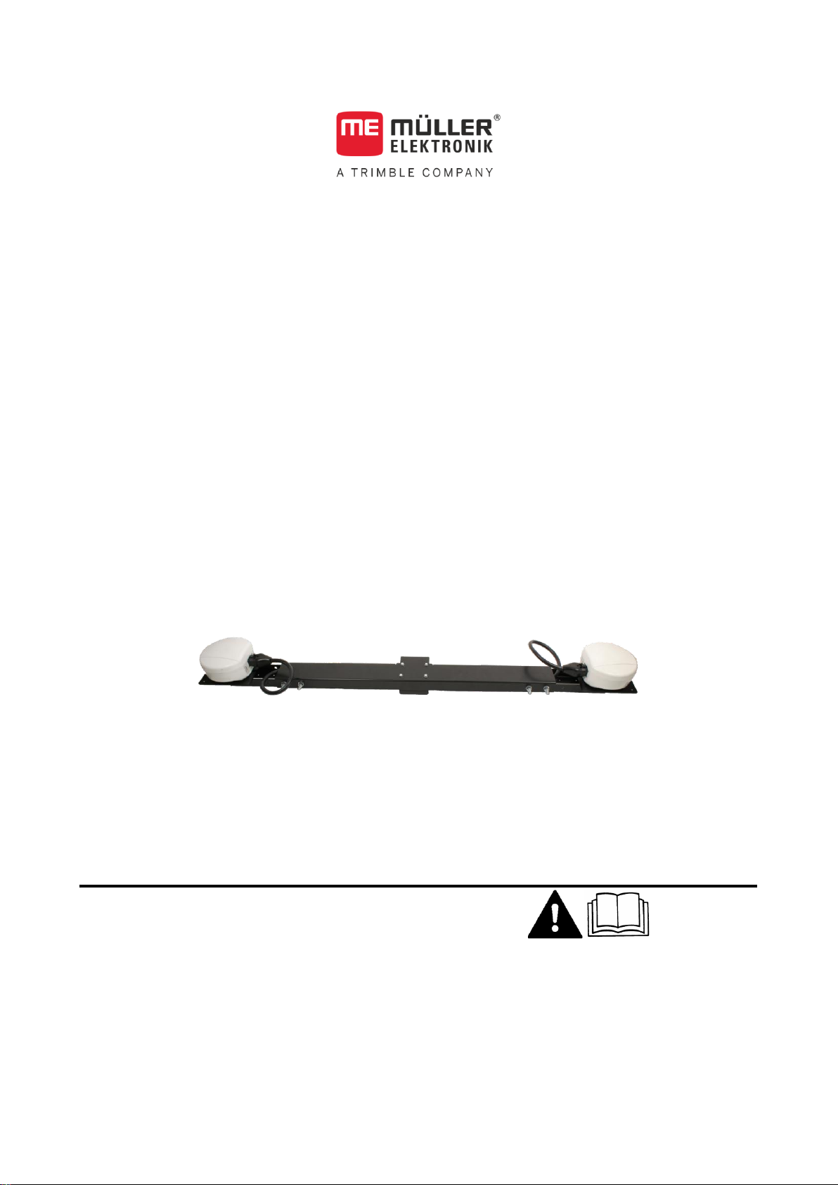
DUAL-Antenna
Version: V4.20180614
3030248960-02-EN
Read and follow these operating instructions.
Keep these operating instructions in a safe place for
later reference.
Page 2

Document
Copyright ©
Company details
Installation Instructions
Product: DUAL-Antenna
Document number: 3030248960-02-EN
Original language: German
Müller-Elektronik GmbH & Co.KG
Franz-Kleine-Straße 18
33154 Salzkotten
Germany
Phone: ++49 (0) 5258 / 9834 - 0
Fax: ++49 (0) 5258 / 9834 - 90
Email: info@mueller-elektronik.de
Homepage: http://www.mueller-elektronik.de
Page 3

Table of contents
V4.20180614
3
1
For your safety
4
1.1
Basic safety instructions
4
1.2
Intended use
4
1.3
Layout and meaning of warnings
5
1.4
Disposal
5
2
Product description
6
3
Assembly instructions
7
3.1
Attaching the GPS receiver on the main bar
7
3.2
Installing the main bar on the roof
8
3.2.1
Installation with standard angle bracket
8
3.2.2
Installation with additional components
9
3.3
Connecting the components
10
4
List of accessories
11
Table of contents
Page 4

1
For your safety
Basic safety instructions
4
3030248960-02-EN
1
1.1
1.2
For your safety
Basic safety instructions
Please read the following safety instructions carefully before using the product for
the first time.
▪ Do not make any unauthorized modifications to the product. Unauthorized
modifications or use may impair safety and reduce the service life or operability
of the unit. Modifications are considered unauthorized if they are not described
in the product documentation.
▪ Comply with road traffic rules. Stop the vehicle before operating the GPS
receiver or connected components.
Systems with modem
If you use the GPS receiver with a modem, note that the modem emits radio waves
when switched on. These can interfere with other devices or be harmful to human
health.
You should therefore follow the following instructions when using the GPS receiver
with a modem:
▪ If you wear a medical device, ask your doctor or the device manufacturer about
how to prevent hazards. Medical devices such as pacemakers or hearing aids
can be affected by the radio transmissions of modems.
▪ If you wear a pacemaker, keep the modem away from the pacemaker.
▪ Switch off the modem as soon as you are close to petrol stations, chemical
plants, biogas plants or other locations where combustible gases or fumes can
occur. These gases can be ignited by a spark and explode.
▪ Maintain a minimum distance of 20 cm (8 inches) between the antenna of the
modem and your body.
▪ Never switch on the modem in an aircraft. Ensure that it is not accidentally
switched on during flight.
Intended use
The product is intended for accurate positioning of agricultural vehicles.
The product is only intended for use in the agricultural sector. The manufacturer
shall not be held responsible for any other use of the system.
The operating instructions form part of the product. The product may only be used in
accordance with these operating instructions.
The manufacturer cannot be held liable for any personal injury or property damage
resulting from such non-compliance. All risk arising from improper use lies with the
user.
Page 5

For your safety
Layout and meaning of warnings
1
V4.20180614
5
WARNING
This signal word identifies medium-risk hazards, which could potentially cause
death or serious physical injury, if not avoided.
CAUTION
This signal word identifies hazards that could potentially cause minor or moderate
physical injury or damage to property, if not avoided.
NOTICE
This signal word identifies hazards that could potentially cause damage to property,
if not avoided.
When it has reached the end of its service life, please dispose of this
product as electronic scrap in accordance with all applicable waste
management laws.
1.3
Example
1.4
Layout and meaning of warnings
All safety instructions found in these Operating Instructions are composed in
accordance with the following pattern:
There are some actions that need to be performed in several steps. If there is a risk
involved in carrying out any of these steps, a safety warning appears in the
instructions themselves.
Safety instructions always directly precede the step involving risk and can be
identified by their bold font type and a signal word.
1. NOTICE! This is a notice. It warns that there is a risk involved in the next
step.
2. Step involving risk.
Disposal
Page 6

2
Product description
6
3030248960-02-EN
Junction box
Guard brackets
Angle brackets
Main bar
Accessories bag with fastening
material
Receiver fixture
Angle brackets
Adjustable feet
Bolts with spacer sleeves
2
Product description
The DUAL-Antenna system with a second GPS receiver allows working with
centimeter accuracy even at extremely low speeds. The lowest possible speed is
80m/h.
To work with the system, you must add a second receiver to your existing system
consisting of a DGPS/GLONASS receiver SMART-6L and a GSM modem.
In addition to the second GPS receiver, you also need the following components to
be able to work with the DUAL-Antenna system:
With some systems (e.g. Fendt), we recommend that the following additionally
supplied components be used:
Page 7

Assembly instructions
Attaching the GPS receiver on the main bar
3
V4.20180614
7
Step
Procedure
Be sure to measure the width of the roof of your tractor. The main bar
may not protrude later on. The possible length of the main bar is 1m to
1.5m.
As an option, you can also install the guard bracket at the desired
position. To do so, use the additional supplied screws, e.g.:
3
3.1
Procedure
Assembly instructions
Attaching the GPS receiver on the main bar
Page 8

3
Assembly instructions
Installing the main bar on the roof
8
3030248960-02-EN
Step
Procedure
Please note that you must install the GPS receiver with RTK activation
on the left side in the driving direction.
3.2
3.2.1
Procedure
Installing the main bar on the roof
To install the main bar on the roof, you can either use the supplied angle brackets or
attach the main bar individually.
Depending on the tractor model, you can use the standard angle bracket or an angle
bracket with additional adjustable feet.
Please note that the images are only examples. The appearance of the roof can
differ from one tractor model to another.
Installation with standard angle bracket
Proceed as follows if the standard angle bracket is used without the additional
components.
There is no GPS receiver on the tractor roof.
1. - Remove the screws from the tractor roof.
Page 9

Assembly instructions
Installing the main bar on the roof
3
V4.20180614
9
3.2.2
Procedure
2. - Position the angle bracket and re-tighten the screws.
3. Make sure that the screws are sealed after tightening.
4. Center the main bar on the angle brackets. The main bar may not protrude over
the edge of the roof. Please note that the connection for the GPS receiver must
face the rear.
5. Attach the main bar firmly with the supplied screws.
Installation with additional components
Proceed as follows if the additional angle bracket is used with the additional
components.
There is no GPS receiver on the tractor roof.
1. - Look for the screw fasteners above the
doors.
2. - Screw the additional angle bracket using the spacer
sleeves onto the screw fasteners above the doors.
3. Center the main bar on the additional angle brackets. The main bar may not
protrude over the edge of the roof. Please note that the connection for the GPS
receiver must face the rear.
4. - Install the
adjustable feet between the main bar and the tractor roof to prevent vibrations.
5. Screw on the main bar firmly.
Page 10

3
Assembly instructions
Connecting the components
10
3030248960-02-EN
NOTICE
Kink damage to the antenna cable
The antenna cable can become damaged if it is bent during installation.
◦ Do not bend the antenna cable.
3.3
Procedure
Connecting the components
To connect the components:
You have installed the holding bar with the GPS receivers.
You have installed the connection box for the GSM modem. You can find more
information on the installation of the GSM modem in the corresponding
instructions.
1. Route the GPS receiver cable from the GSM modem connection box out of the
vehicle cab.
2. Connect the cable to the the junction box on the main bar.
3. Check whether the connection box of the GSM modem is still correctly
connected with the antenna and the steering job computer.
⇨ You have successfully connected the components.
Page 11

List of accessories
4
V4.20180614
11
Item number
Item name
3030248960
DUAL-Antenna upgrade kit with DGPS/GLONASS receiver SMART-6L, junction box
and roof bracket for 2 GPS receivers
3030247607
DGPS/GLONASS receiver SMART-6L for DUAL-Antenna systems
3130248960
Roof bracket for 2 GPS receivers with fastening material
3130248920
Junction box for 2 GPS receivers
3030248961
DGPS/GLONASS receiver SMART-6L activation for DUAL-Antenna system
3130264341
ECU-S1 activation for extremely low speeds
4
List of accessories
DUAL-Antenna – Components
Page 12

Page 13

 Loading...