

Page 1
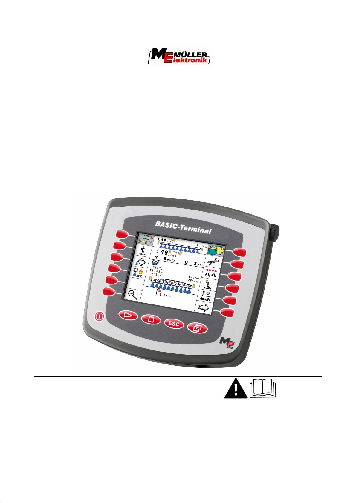
Installation and operating instructions
BASIC-Terminal
Version: 20110308
30322511-02-EN Read and follow these operating instructions.
Keep these operating instructions in a safe place for later
reference.
Page 2

Imprint
Document
Copyright ©
Installation and operating instructions
Product: BASIC-Terminal
Document number: 30322511-02-EN
Valid for item number: 30322511, 30322512
From software version: 3.68
Original language: German
Müller-Elektronik GmbH & Co.KG
Franz-Kleine-Straße 18
33154 Salzkotten
Germany
Phone: ++49 (0) 5258 / 9834 - 0
Fax: ++49 (0) 5258 / 9834 - 90
Email: info@mueller-elektronik.de
Homepage: http://www.mueller-elektronik.de
Page 3

Contents
Contents
1 For your safety 25
1.1 Basic safety instructions
1.2 Layout and meaning of warnings
1.3 User requirements
1.4 Intended use
1.5 EC declaration of conformity
2 About these Operating Instructions 27
2.1 Target group of these Operating Instructions
2.2 Layout of operating instructions
2.3 Layout of references
3 Product description 28
3.1 Performance description
3.2 Scope of delivery
3.3 System requirements
3.4 Correctly interpreting information on the nameplate
4 Mounting and installation 210
4.1 Instructions on retrofitting
210
25
25
26
26
26
27
27
27
28
28
28
29
4.2 Mounting the terminal in the tractor cab
211
4.2.1 Screwing on the GSM antenna 211
4.2.2 Terminal ports 212
4.3 Connecting the terminal to the basic equipment 212
4.3.1 Checking the ISOBUS compatibility of the basic equipment 213
4.3.2 Selecting the correct basic equipment 213
4.3.3 Connecting the terminal to the basic equipment 214
5 Basic control principles 215
5.1 Getting to grips with the controls
5.2 Using the function keys
5.3 Initial start-up
5.4 Restarting the terminal
215
216
217
218
6 Opening applications in the selection menu 220
6.1 Display layout in the selection menu
6.2 Opening applications
6.3 Segmentation of the display
220
221
221
7 Configuring the terminal in the Service application 223
7.1 Controls in the Service application
7.2 Icons in the Service application
Copyright © Müller-Elektronik GmbH & Co.KG 3
223
224
Page 4

Contents
7.3 Changing the language 224
7.4 Adjusting the brightness for day or night mode
7.5 Configuring the basic display settings
7.6 Activating and deactivating applications
7.7 Activating licences for full v
7.8 Deleting files from th
ersions of the software 228
e USB flash drive 229
7.9 Deleting pools
7.10 GPS Receiver
225
226
227
230
231
7.10.1 Activating the GPS Receiver 231
7.10.2 Configuring the DGPS Receiver A100 232
7.11 Configuring the "GPS TILT-Module" terrain compensation 234
7.12 Screenshots
7.12.1 Configuring the screenshots function 235
7.12.2 Creating screenshots 236
235
7.13 Activating the "Diagnostics" function 236
7.13.1 Jobcomputer diagnostics 237
Sending diagnostic data to the portal
237
7.13.2 CAN-Trace settings 237
7.14 Activating an external LightBar 238
7.15 Camera
239
7.15.1 Activating a camera 239
7.15.2 Operating the camera 240
7.16 Configuring FarmPilot 241
7.16.1 Activating FarmPilot 241
7.16.2 Configuring the connection with FarmPilot 242
7.16.3 Entering data in the FarmPilot access data section 243
7.16.4 Configuring the GPRS connection manually 244
8 Maintenance and servicing 246
8.1 Servicing and cleaning the terminal
8.2 Disposing of the unit
8.3 Checking the software version
8.4 Technical specifications
8.4.1 Technical specifications of the terminal 246
8.4.2 Pin assignment of ports A and B 247
8.4.3 Pin assignment of port C 248
8.4.4 Pin assignment of camera ports 1 and 2 249
9 Notes 251
246
246
246
246
4 Copyright © Müller-Elektronik GmbH & Co.KG
Page 5
1
For your safety
For your safety
Basic safety instructions
1
1.1
1.2
Basic safety instructions
Please read the following safety instructions carefully before using the equipment for the first time.
▪ Before maintenance or repair to the tractor, always disconnect the connection between the
tractor and the terminal.
▪ Before charging the tractor battery, always disconnect the connection between the tractor and
the terminal.
▪ Before performing any welding operations on the tractor or a trailed machine, always disconnect
the power supply to the terminal.
▪ Keep the terminal and its accessory components in good working order.
▪ Do not make any unauthorised modifications to the equipment. Unauthorised modifications or
use may impair operability and/or safety and reduce the service life of the unit. Modifications are
considered unauthorised if they are not described in the product documentation.
▪ Never remove any safety mechanisms or signs from the machine.
▪ Observe all applicable regulations on accident prevention.
▪ Follow all recognised safety, industrial and medical rules as well as all road traffic laws.
Layout and meaning of warnings
All safety instructions found in these Operating Instructions are composed in accordance with the
following pattern:
WARNING
This signal word identifies medium-risk hazards, which could potentially cause death or serious
bodily injury, if not avoided.
CAUTION
This signal word identifies low-risk hazards, which could potentially cause minor or moderate bodily
injury or damage to property, if not avoided.
NOTICE
This signal word identifies actions which could lead to operational malfunctions if performed
incorrectly.
These actions require that you operate in a precise and cautious manner in order to produce
optimum work results.
There are some actions that need to be performed in several steps. If there is a risk involved in
carrying out any of these steps, a safety warning will appear in the instructions themselves.
Safety instructions always directly precede the step involving risk and can be identified by their bold
Example
Copyright © Müller-Elektronik GmbH & Co.KG 5
font type and a signal word.
1. NOTICE! This is a notice. It warns that there is a risk involved in the next step.
Page 6

For your safety
1
User requirements
2. Step involving risk.
1.3
1.4
User requirements
▪ Learn how to operate the terminal correctly. The terminal must not be operated by anyone who
has not read the Operating Instructions.
▪ Please read and carefully observe all safety instructions and warnings contained in these
Operating Instructions and in the manuals of any connected machines and farm equipment.
▪ If there is anything within these Operating Instructions that you do not understand, please do not
hesitate to contact us or your dealer. Müller-Elektronik's Customer Services department will be
happy to assist you.
Intended use
BASIC-Terminal is intended exclusively for use in agriculture as well as in wine-growing, fruitcultivating, and hop-growing operations. The manufacturer cannot be held responsible for any
installation or use of the system that deviates from or exceeds the scope of intended use.
The manufacturer cannot be held liable for any personal injury or property damage resulting from
such improper use. All risks involved in engaging in improper usage, lie solely with the user.
Intended use is also understood to include adherence to the conditions for operation and repair as
prescribed by the manufacturer.
All applicable accident prevention regulations and all other generally recognised safety, industrial,
and medical standards as well as all road traffic laws must be observed. Any unauthorised
modifications made to the equipment will void the manufacturer's warranty.
1.5
EC declaration of conformity
This product has been manufactured in conformity with the following national and harmonised
standards as specified in the current EMC Directive 2004/108/EC:
▪ EN ISO 14982
6 Copyright © Müller-Elektronik GmbH & Co.KG
Page 7
2
About these Operating Instructions
About these Operating Instructions
Target group of these Operating Instructions
2
2.1
2.2
Target group of these Operating Instructions
These Operating Instructions are intended for personnel entrusted with installing and operating the
terminal.
Layout of operating instructions
The operating instructions explain step by step how you can perform certain operations with the
product.
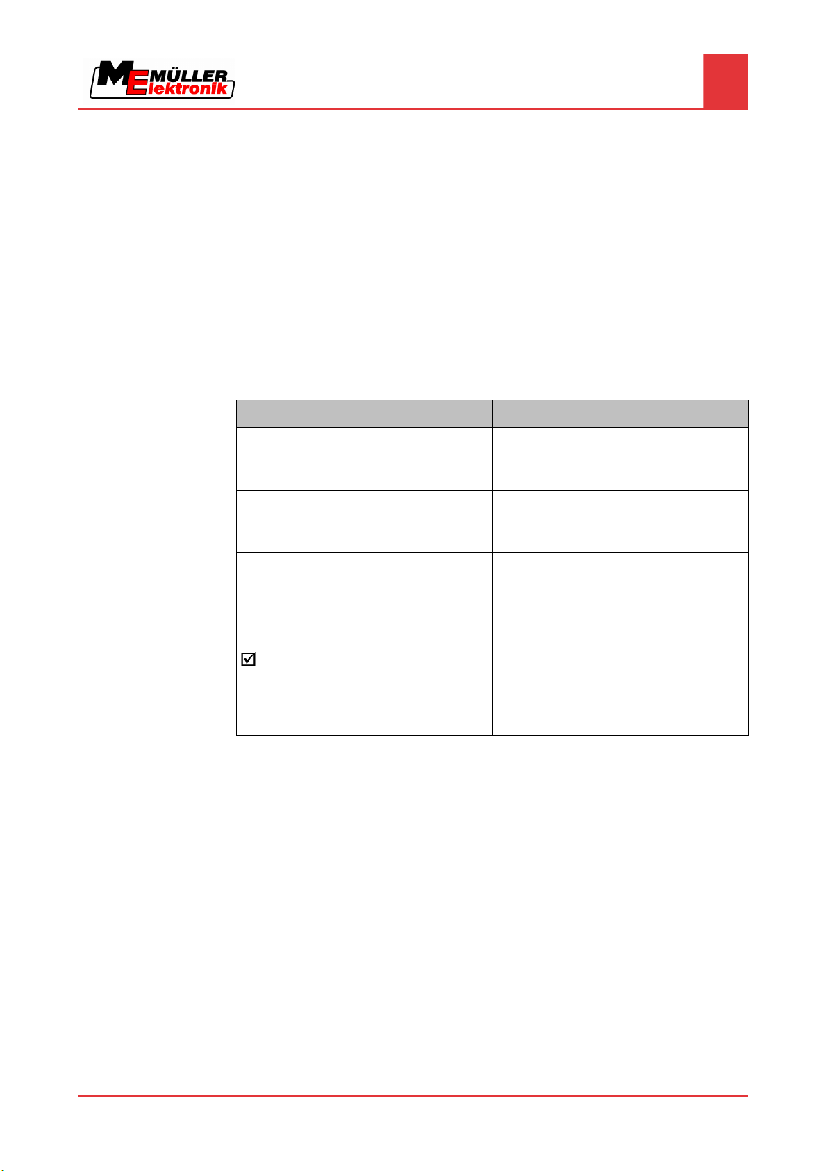
We use the following symbols throughout these Operating Instructions to identify different operating
instructions:
Type of depiction Meaning
1.
2.
⇨
⇨
Actions that must be performed in succession.
Result of the action.
This will happen when you perform an action.
Result of an operating instruction.
2.3
Layout of references
If any references are given in these Operating Instructions, they will appear thus:
Example of a reference: [➙ 7]
References can be identified by t
shows you on what page the chapter starts where you can find further information.
This will happen when you have completed all
steps.
Requirements.
In the event that any requirements have been
specified, these must be met before an action
can be performed.
heir square brackets and an arrow. The number following the arrow
Copyright © Müller-Elektronik GmbH & Co.KG 7
Page 8
3
Product description
3
Performance description
Product description
3.1
Performance description
Components
Installed software
Optional software
The terminal is equipped with the following components:
▪ Interface for controlling the ISOBUS jobcomputer.
The terminal comes with the following software installed as standard:
▪ TRACK-Leader II – 50-hour trial version
▪ SECTION-Control – 50-hour trial version
▪ HEADLAND-Control – 50-hour trial version
Optionally you can activate the following software:
▪ TaskManager – task processing
▪ TRACK-Leader II – parallel tracking system
▪ TRACK-Leader TOP – automatic steering system
▪ SECTION-Control – automatic boom section switching
▪ HEADLAND-Control – headland management.
▪ FIELD-Nav – navigation to the field
Please call our sales department if you want to unlock this optional software.
Differences between the two versions of the terminal
There are two versions of the terminal:
▪ BASIC-Terminal item no.: 30322511
▪ BASIC-Terminal GSM item no.: 30322512
3.2
3.3
You can identify which terminal you have, from the ME item number on the nameplate [➙ 9].
The following table shows the dif
BASIC-Terminal BASIC-Terminal GSM
- GSM modem and GSM antenna
- Camera
Scope of delivery
The following items are included in delivery:
▪ Terminal BASIC-Terminal
▪ Installation and Operating Instructions
▪ Bracket for mounting the terminal
▪ USB flash drive
System requirements
The following requirements must be met for the tractor to be used in conjunction with the terminal:
▪ The tractor must be ISOBUS-capable.
ferences in equipment for both versions.
8 Copyright © Müller-Elektronik GmbH & Co.KG
Page 9
Product description
Correctly interpreting information on the nameplate
3
If your tractor is not ISOBUS-capable, you can upgrade it. Our staff will be glad to advise you on
selecting compatible components.
3.4
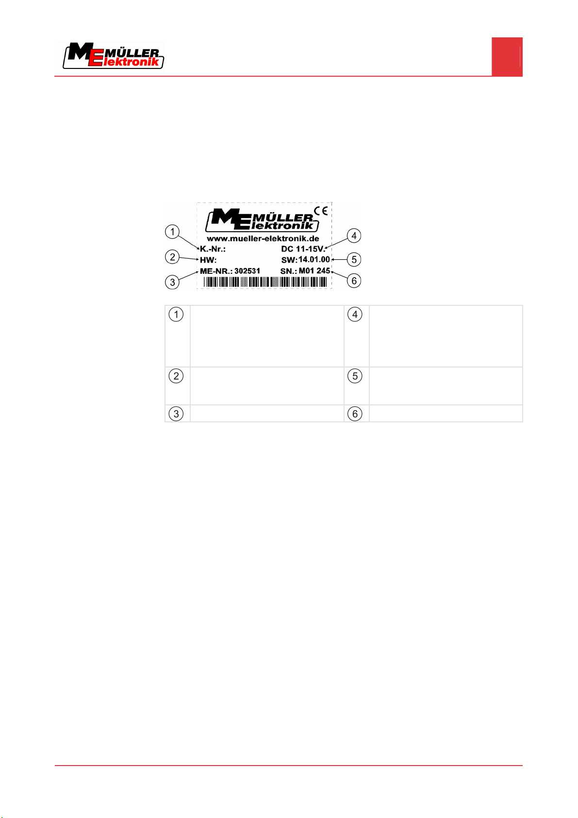
Correctly interpreting information on the nameplate
On the reverse of the terminal you will find a nameplate sticker. On this sticker you can find all the
information you need to definitively identify the product.
Have these details ready when you contact Customer Services.
Nameplate on the reverse of the terminal
Customer number
If the product was manufactured for an
agricultural machinery manufacturer, the
agricultural machinery manufacturer's item
number will be shown here.
Hardware version
Müller-Elektronik item number
Operating voltage
The product may only be connected to
voltages within this range.
Software version
If you update the software, this version will no
longer be up-to-date.
Serial number
Copyright © Müller-Elektronik GmbH & Co.KG 9
Page 10

4
Mounting and installation
4
Instructions on retrofitting
Mounting and installation
Mount the terminal and all additional components in the following order:
1. BASIC-Terminal – mount inside the tractor cab.
2. Connect the terminal to the basic equipment.
3. Connect the terminal to other components.
4.1
Instructions on retrofitting
Selecting components
User responsibility
Refer to the following chapters to learn how to perform these steps.
Instructions on how to retrofit electrical and electronic farm equipment and/or
components
Agricultural equipment used today features electronic components and parts whose function can be
affected by other farm equipment which emits electromagnetic waves. Such effects could lead to
personnel being put in danger, if the following safety instructions are not adhered to.
When selecting components, make sure first of all, that the retrofitted electrical and electronic
components comply with the current version of the EMC Directive 2004/108/EC and carry the CE
marking.
When retrofitting a machine with electrical and electronic farm equipment and/or components
connected to the vehicle's electrical system, it is your own responsibility to check whether the
installation causes interference with the vehicle's electronic system or other components. This
applies, in particular, to the electronic control of:
▪ EHR,
▪ front linkage,
▪ take-off shafts,
▪ engine,
▪ gear.
Additional requirements
The following requirements must be met in order to retrofit mobile communication systems (e.g. radio,
phone):
▪ All farm equipment must be approved and installed in accordance with the regulations applicable
in the respective country (e.g. in Germany, the Federal Approvals Office for Telecommunications
(BZT)).
▪ The equipment must be installed as a fixed installation.
▪ The operation of portable or mobile farm equipment in the interior of the vehicle is only permitted
via a connection to a permanently installed exterior antenna.
▪ The transmitting part must be spatially separated from the vehicle's electronic system.
▪ When attaching the antenna, pay attention to proper installation, including a sound ground
connection between the antenna and the vehicle's ground wire.
For information on wiring and installation as well as the maximum allowable current consumption,
please also refer to the installation guide provided by the machine manufacturer.
10 Copyright © Müller-Elektronik GmbH & Co.KG
Page 11
Mounting and installation
Mounting the terminal in the tractor cab
4
4.2
Procedure
Mounting the terminal in the tractor cab
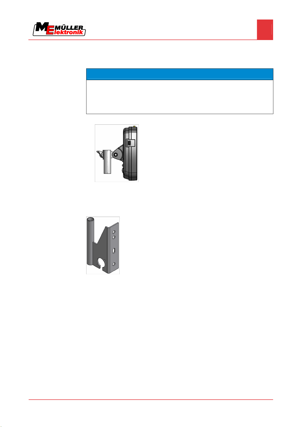
NOTICE
Electromagnetic interference
The operation of the terminal may be impaired by electromagnetic waves emitted by other farm
equipment.
◦ Mount the terminal at least 1 m away from the radio antenna or from a radio device.
1. Screw the bracket to the terminal.
2. Mount the terminal with the bracket installed inside the tractor cab.
For instance, you can use the ME base console for this purpose.
The base console is not included with the terminal. This is included in the delivery content of the
ISOBUS basic equipment [➙ 13].
4.2.1
Procedure
Screwing on the GSM antenna
Base console
The GSM antenna transmits information to the FarmPilot portal via a mobile phone network.
1. NOTICE! There is a very sensitive contact pin in the centre of the GSM antenna. Make
sure not to damage the contact pin when screwing on the GSM antenna.
2. Screw the GSM antenna onto the top of the terminal.
Copyright © Müller-Elektronik GmbH & Co.KG 11
Page 12
Mounting and installation
4
Connecting the terminal to the basic equipment
4.2.2
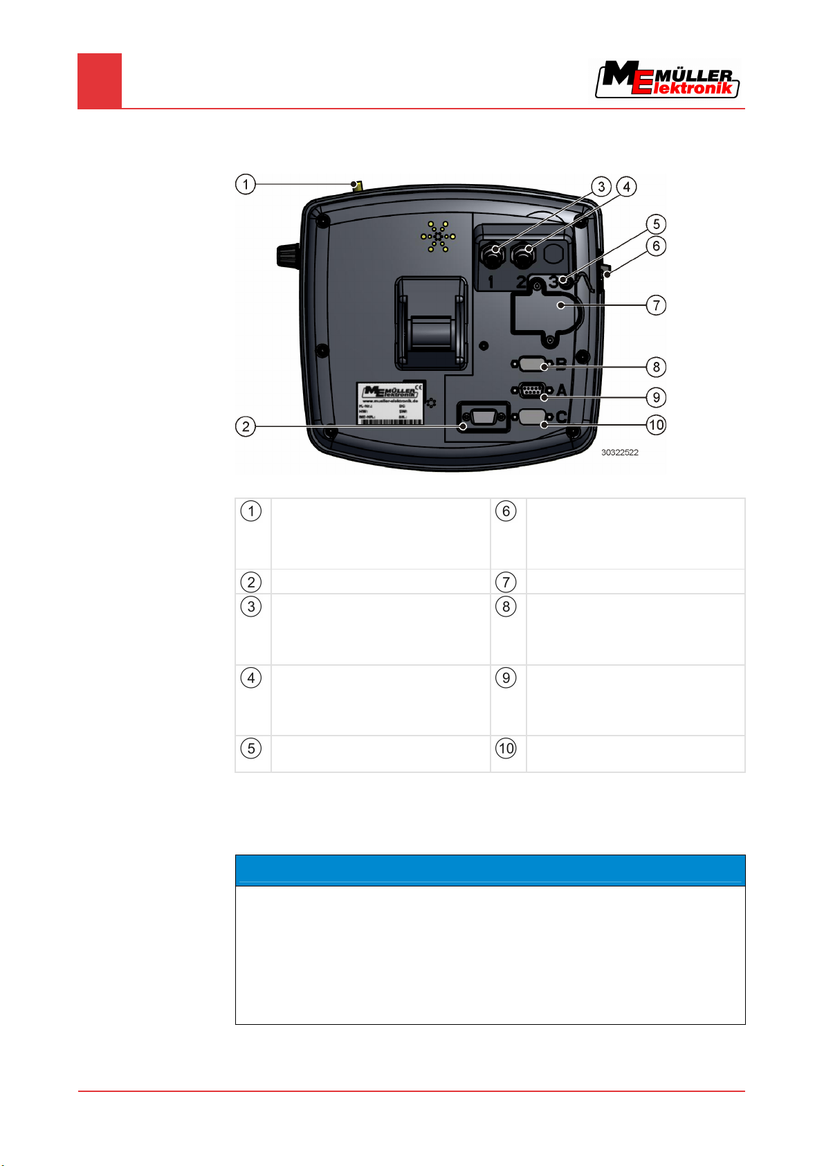
Terminal ports
Reverse of the terminal BASIC-Terminal
GSM antenna port
Only for terminals with a GSM modem
installed.
Item no. 30322512
Not currently in use
Port for analogue camera
Only for terminals with a GSM modem
installed.
Item no. 30322512
Port for analogue camera
Only for terminals with a GSM modem
installed.
Item no. 30322512
Covering cap for USB port
Prevents dust from entering the USB socket.
USB port
USB 1.1
SIM card slot
Port B
CAN bus port
To connect a working position sensor for
TRACK-Leader 2
Port A
CAN bus port
To connect the ISOBUS basic equipment.
Port C
Serial port RS232
4.3
Connecting the terminal to the basic equipment
NOTICE
Risk of damage when using non-standard basic equipment.
Connecting the terminal to non-standard basic equipment may damage both the terminal and the
12 Copyright © Müller-Elektronik GmbH & Co.KG
basic equipment.
◦ Before connecting the terminal to any existing basic equipment, check that the equipment
conforms to ISO 11783.
◦ Do not connect the terminal to any basic equipment that does not comply with ISO 11783.
Page 13

Mounting and installation
Connecting the terminal to the basic equipment
4
4.3.1
4.3.2
Checking the ISOBUS compatibility of the basic equipment
The basic equipment provided by Müller-Elektronik is ISO 11783-compatible and labelled with the
following sticker on the ISOBUS socket:
Selecting the correct basic equipment
You must select basic equipment that matches the fittings of the vehicle in which the terminal BASICTerminal is to be installed.
The following types of basic equipment are available:
▪ Basic equipment for ISOBUS tractors
▪ Basic equipment for tractors without signal capture
▪ Basic equipment for retrofitting tractors and for signal capture.
Basic equipment for ISOBUS tractors
Item name: Basic equipment BASIC – Terminal / -TOP for ISOBUS tractors (ISO 11783) with
ISOBUS terminal connector
(Item no.: 30322541)
Suitable for:
▪ Tractors with a power socket for connecting the ISOBUS basic equipment. The power socket
must conform to ISO 11783.
In this case, only one connecting cable is required to link the terminal to the tractor bus and the power
supply.
Basic equipment for tractors without signal capture
Item name: Basic equipment BASIC – Terminal / -TOP without tractor jobcomputer
(Item no.: 30322550)
Suitable for:
▪ Tractors without signal capture.
Basic equipment for retrofitting tractors and for signal capture.
Item name: Basic equipment BASIC – Terminal / -TOP with tractor jobcomputer
Suitable for retrofitting tractors and for signal capture.
Copyright © Müller-Elektronik GmbH & Co.KG 13
Page 14

Mounting and installation
4
Connecting the terminal to the basic equipment
This basic equipment is available in two models:
▪ Connection via an adapter cable to the tractor's existing signal socket (DIN 9684.1 / ISO 11786).
(Item no.: 30322560)
▪ Equipping the tractor jobcomputer with sensors (km/h transmission, km/h radar, PTO speed and
work position). This equipment offers the possibility of fitting the tractor with a front and rear
power socket. (Item no.: 30322565)
4.3.3
Procedure
Connecting the terminal to the basic equipment
1. Insert the 9-pin cable of the basic equipment into the 9-pin socket A on the terminal.
2. Tighten the safety screws on the connector.
14 Copyright © Müller-Elektronik GmbH & Co.KG
Page 15
5
Basic control principles
Basic control principles
Getting to grips with the controls
5
5.1
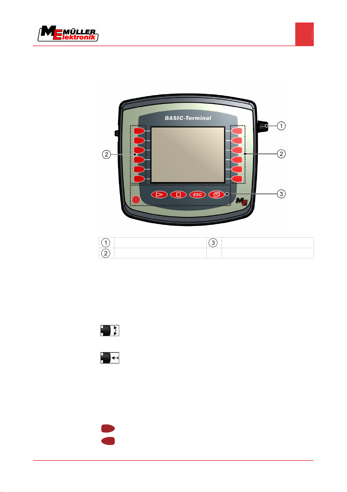
Getting to grips with the controls
Terminal controls
Rotary knob
Function keys
Keys
Controls
Rotary knob
The rotary knob is located in the top right hand corner of the terminal.
Control with the rotary knob may vary slightly between the different applications.
You can use the rotary knob to perform the following actions:
Turning the rotary knob:
▪ Move the cursor up and down.
▪ Change a parameter value.
Pressing the rotary knob:
▪ Click on the selected line.
▪ Activate parameter.
▪ Confirm input.
Function keys
Operating the function keys is the same across all applications.
Performing the functions depicted on the display
Copyright © Müller-Elektronik GmbH & Co.KG 15
Page 16
Basic control principles
5
Using the function keys
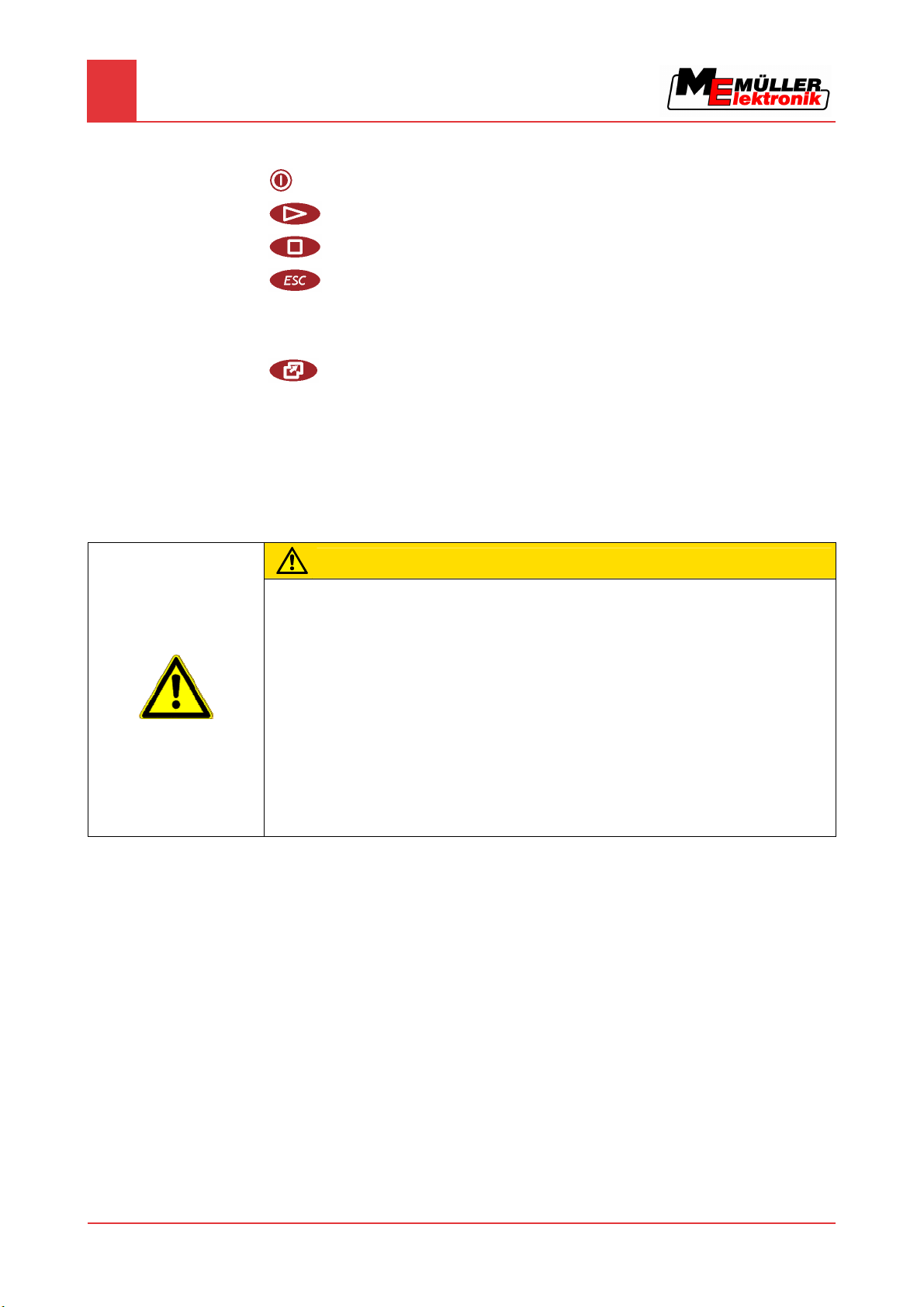
Keys
5.2
Switch the terminal on and off
Has no function
Has no function
Exit screen
Cancel input
Hide warning messages and alerts
Open the "Selection menu" application
Exit the "Selection menu" application
Using the function keys
Whenever you use the function keys, you will activate the function depicted on the adjacent function
icon.
CAUTION
Danger of pressing the function keys without care
When pressing function keys, components of the connected machine can be moved or activated.
As a result, people can be injured and property damaged.
Before pressing a function key:
◦ Make sure you know what will happen when you press the function key.
◦ Consult the Operating Instructions of the connected machine or of the agricultural equipment to
establish what dangers could arise from pressing that key.
◦ Fulfill all the measures described in the machine's Operating Instructions in order to avoid
danger.
◦ Only press the function key when you are sure that no danger is posed to people or property.
When you press a function key, the function / operation depicted on the function icon will be
performed.
16 Copyright © Müller-Elektronik GmbH & Co.KG
Page 17

Basic control principles
Initial start-up
5
Example
5.3
Procedure
Using the function keys
When you press the function key , the function depicted on the function icon will be
activated.
If not function icon appears next to a function key, this means that this function key has no function at
present.
Initial start-up
1. Installing and connecting the terminal.
2.
3. Wait for approx. 15 seconds until all applications have been loaded.
4.
Function icon
Depiction of an available function.
- Switch on the terminal.
- Open the "Selection menu" application.
⇨ The following screen will appear:
Function key
Performs the function depicted on the function
icon.
Copyright © Müller-Elektronik GmbH & Co.KG 17
Page 18

Basic control principles
5
Restarting the terminal
⇨ You are now in the selection menu.
⇨ Now the connected jobcomputers will be loaded. The progress of this process is indicated
by the progress bar next to the jobcomputer icon. The time taken to complete this process
depends on the number of connected jobcomputers.
5. Wait until all jobcomputers have been loaded.
⇨ The following screen will appear:
All jobcomputers are loaded when no more progress bars are displayed.
6. In the selection menu you can select which application you wish to display next.
7.
- Select the "Service" line. The "Service" line must be framed by a black square:
8.
- Click on the "Service" line.
⇨ The following screen will appear:
⇨ You have opened the "Service" application.
5.4
Restarting the terminal
9. Configuring the terminal in the Service application [➙ 23]
When restarting the terminal, you must give the connected jobcomputers enough time to restart as
well. For this reason, always wait approx. 30 seconds after switching off the terminal before switching
Procedure
18 Copyright © Müller-Elektronik GmbH & Co.KG
the terminal back on.
1. - Switch off the terminal.
Page 19

Basic control principles
Restarting the terminal
5
2. Wait 30 seconds until the jobcomputers have also been switched off.
3.
- Switch on the terminal.
Copyright © Müller-Elektronik GmbH & Co.KG 19
Page 20

6
Opening applications in the selection menu
6
Display layout in the selection menu
Opening applications in the selection menu
In the selection menu you can choose which application you wish to view on the display.
Controls
6.1
You can open the selection menu at any time. This will not close the application currently running.
Open the selection menu
Press again – open the most recently activated application
Display the application in the header of the split display.
Display the application in the main section of the display.
Display layout in the selection menu
The display is split into the following sections:
▪ Function icons – left and right
▪ Applications section – in the middle, between the function icons.
20 Copyright © Müller-Elektronik GmbH & Co.KG
Sections in the selection menu
Name of an application
Function icons on the left
Select an application which will later be
displayed in the header.
Selection
The selected application is displayed in the
header
ISO ID of the application
ISO name of the application
Selection
The selected application is displayed on the
main display.
Function icons on the right
Open an application on the main display.
Cursor
Open the selected application using the rotary
knob.
Page 21

Opening applications in the selection menu
Opening applications
6
6.2
Procedure
Opening applications
You can perform the following actions in the selection menu:
▪ Open an application.
▪ Display an application in the header of the split display.
1. - Set which application is to be displayed in the header of the split display.
⇨ The function icon of the selected application is marked with a dot on the left hand side:
2. Start the application for the main display. There are several ways to do so:
With the rotary knob:
- Select the desired application
- Open the selected application
Using the function keys on the right hand side:
- Display the application shown next to the function icon.
⇨ Both applications will appear on the display.
6.3
Segmentation of the display
The display of the terminal BASIC-Terminal is split into two sections.
A different application is diplayed in each section. This allows you, for example, to control the tractor
on the field and monitor the field sprayer at the same time. This means that you will not need an
additional terminal.
Copyright © Müller-Elektronik GmbH & Co.KG 21
Segmentation of the display
Header – section used to display information.
The header allows you to display information
about an application.
Main display – section used for control.
The main display shows the application
currently running, function icons and the
information you need to control the application
that is currently running.
Page 22

6
Controls
Opening applications in the selection menu
Segmentation of the display
In the selection menu you can see which applications can be run with the split display.
Function icon Function
Switch applications in the header section.
Swap applications between the header section and the main section of the
display.
22 Copyright © Müller-Elektronik GmbH & Co.KG
Page 23

7
Configuring the terminal in the Service application
Controls in the Service application
Configuring the terminal in the Service application
In the "Service" application you can configure the terminal and activate the connected farm
equipment.
Once you have started the "Service" application, the following screen will appear:
Start screen of the "Service" application
Main section
Screen contents
Version number
Name of the terminal and version of the
installed software
Cursor
Selects a line that can be clicked on with the
rotary knob
Function icons section
Icons that can be pressed on this screen.
7
7.1
Controls
Controls in the Service application
The "Service" application is controlled using the rotary knob and the function keys.
Some of the function icons explained here will only appear if a specific function is activated. This
limits the information shown on the display to just the information that you need for your work.
Function icon Meaning Appears only if...
Scroll There is one more page with
Back
Activate day mode
Activate night mode
File cannot be deleted (grey) Selected object cannot be
function icons.
deleted
Copyright © Müller-Elektronik GmbH & Co.KG 23
Page 24

Configuring the terminal in the Service application
7
Icons in the Service application
Function icon Meaning Appears only if...
Delete file (red) Selected object can be deleted
Configure GPS Receiver GPS Receiver is activated
Configure FarmPilot FarmPilot portal is activated
Open the Diagnostics screen Diagnostics is activated
Retrieve default values.
7.2
Icons
7.3
Procedure
Display DGPS connection status
Icons in the Service application
You will find the following icons in the Service application.
Function is activated
Function is deactivated
Changing the language
When you switch on the terminal for the first time, the text may appear in a foreign language (in
German).
In this chapter you will learn how to change the language of the terminal.
1. - Switch on the terminal.
2.
- Press.
24 Copyright © Müller-Elektronik GmbH & Co.KG
Page 25

Configuring the terminal in the Service application
Adjusting the brightness for day or night mode
7
⇨ The following screen will appear:
3.
- Click on "Service".
⇨ The following screen will appear:
The texts on this screen may appear in a foreign language.
4.
5.
6.
7.
- Click on "Terminal Einstellungen“ ("Display settings").
- Click on "Sprache" ("Language").
- Select the abbreviation of your language.
- Press.
⇨ The language in the "Service" application will be changed.
8.
- Restart terminal.
7.4
Procedure
Adjusting the brightness for day or night mode
⇨ The language in other applications will be changed.
In this chapter you will learn how to adjust the brightness of the display for day or night mode.
1. Open the "Service" application:
| Service
Copyright © Müller-Elektronik GmbH & Co.KG 25
Page 26

Configuring the terminal in the Service application
7
Configuring the basic display settings
⇨ The following screen will appear:
2. Change the operating mode.
Depending on which operating mode is currently active, you can use one of the function icons:
– Activate day mode.
7.5
Procedure
– Activate night mode.
⇨ The brightness of the display will be adjusted immediately.
Configuring the basic display settings
The basic display settings can be adjusted on the "Display settings" screen.
1. Switch to the "Display settings" screen:
| Service | Display settings
⇨ The following screen will appear:
List of parameters
2.
Parameter Meaning
- Change the desired parameter.
Brightness
Day Adjust the brightness for day mode
Night Adjust the brightness for night mode
Night mode Switch night mode on and off
26 Copyright © Müller-Elektronik GmbH & Co.KG
Page 27

Configuring the terminal in the Service application
Activating and deactivating applications
7
Parameter Meaning
0 = day mode is activated
1 = night mode is activated
Volume Adjust volume
Date / time
Date Set current date
Time Set current time
Time zone 0 = Time zone: Greenwich Mean Time (GMT)
1 = GMT +1 hour (Germany)
-1 = GMT -1 hour
7.6
Language Select language
Measure Select measure system
- metric
- imperial
- US American
- user-defined
Keyboard brightness Set level of keyboard brightness in percent
Activating and deactivating applications
In the Service application you can activate and deactivate other applications that are installed on the
terminal.
The applications are installed in packages, in so-called plugins. A plugin can contain several
applications.
Name of the plugin Includes the following applications
TaskManager TaskManager
TRACK-Leader TRACK-Leader II
SECTION-Control
TRACK-Leader TOP
Procedure
FIELD-Nav FIELD-Nav
1. Switch to the "Plugin settings" screen:
| Service | Plugin settings
Copyright © Müller-Elektronik GmbH & Co.KG 27
Page 28

Configuring the terminal in the Service application
7
Activating licences for full versions of the software
⇨ The following screen will appear:
7.7
2.
- Click on the desired plugin.
⇨ The icon preceding the name of the plugin indicates whether the plugin is activated or
deactivated.
3.
- Exit screen.
⇨ The following notification will appear:
“Changes will be adopted after restart!“
4.
5.
- Confirm.
- Restart terminal.
⇨ All activated plugins will appear in the selection menu.
Activating licences for full versions of the software
Several applications are pre-installed on the terminal, which you can use for trial purposes for up to
50 hours. After this time has elapsed, they will be automatically deactivated. The amount of free
usage time remaining is shown in brackets next to the name of the application.
To activate a licence you will require an activation number, which you will receive on purchasing an
application from Müller-Elektronik. If you request the activation number by phone or by email, you will
be required to give our staff the following information:
▪ Code – Found under the name of the application on the "Licence management" screen.
▪ Serial number of the terminal – Found on the nameplate on the reverse of the terminal.
▪ Item number of the terminal – Found on the nameplate on the reverse of the terminal.
Procedure
The activation number is entered as follows:
1. Switch to the "Licence management" screen:
| Service | Licence management
28 Copyright © Müller-Elektronik GmbH & Co.KG
Page 29

Configuring the terminal in the Service application
Deleting files from the USB flash drive
7
⇨ The following screen will appear:
2. Click on the desired application.
⇨ The following screen will appear:
7.8
3. Enter the activation number in the "Key" field. You will receive the activation number on
purchasing a software licence.
4. Confirm
⇨ The following icon will appear next to the application on the "Licence management" screen:
⇨ The application is activated. You can use the application without any restrictions.
Deleting files from the USB flash drive
NOTICE
Potential loss of data!
Deleted files cannot be retrieved!
◦ Think very carefully about which file you wish to delete.
On the "File management" screen you can delete files from the USB flash drive.
The "File management" screen only displays files that are stored in either of the following two folders
on the USB flash drive:
▪ Screencopy – contains all screenshots you have created
▪ Taskdata – contains all task data for the "TaskManager" application
Procedure
1. Switch to the "File management" screen:
| Service | File management
Copyright © Müller-Elektronik GmbH & Co.KG 29
Page 30

Configuring the terminal in the Service application
7
Deleting pools
⇨ The following screen will appear:
2. Click on "USB".
⇨ The "Screencopy" and "Taskdata" folders will appear.
⇨ If these folders fail to appear, it is because you did not create them on the USB flash drive.
3. Click on the desired folder.
⇨ The contents of the folder will be displayed.
A folder may either contain files or further folders.
If nothing is displayed, the folder is empty.
4. Select the files to be deleted.
7.9
Deleting pools
When to delete?
Procedure
5.
– Delete file (red)
⇨ Deleting file.
You can delete the pools to speed up the terminal's operation.
Pools are the intermediate storage for the terminal. Pools are used to temporarily store graphics or
text. Over time, the pools will become too large and slow down the operation of the terminal.
▪ After updating the software of a connected jobcomputer.
▪ If the terminal operates more slowly than usual.
▪ When asked to do so by Customer Services.
1. Switch to the "File management" screen:
| Service | File management
⇨ The following screen will appear:
2. Click on "Pools".
⇨ The names of several folders will appear.
⇨ If the pool is empty, nothing will appear.
3. Click on the desired folder.
30 Copyright © Müller-Elektronik GmbH & Co.KG
Page 31

Configuring the terminal in the Service application
GPS Receiver
7
⇨ The contents of the folder will be displayed.
The names of the folders are the ISO IDs of the applications whose temporary data they
store.
4. Select the desired file.
7.10
7.10.1
Procedure
5.
- Delete file.
⇨ Deleting file.
6.
- Restart terminal.
GPS Receiver
When you connect a GPS Receiver to the terminal, you must activate and configure it.
Activating the GPS Receiver
In order to activate the GPS Receiver, you must first activate its driver.
A driver is a small program that controls connected farm equipment. The drivers for the farm
equipment supplied by Müller-Elektronik are pre-installed on the terminal.
1. Switch to the "Driver settings" screen:
| Service | Driver settings
⇨ The following screen will appear:
2. Select "GPS".
3. Click on "GPS".
Copyright © Müller-Elektronik GmbH & Co.KG 31
Page 32

Configuring the terminal in the Service application
7
GPS Receiver
⇨ The installed drivers will appear.
7.10.2
⇨ Next to the active driver the icon
⇨ The driver "GPS_A100" for the DGPS Receiver A100 from Müller-Elektronik comes
activated as standard.
4. Select the line containing the correct antenna driver:
GPS_A100 – if the DGPS Receiver was connected directly to the terminal (port C)
GPS_PSRCAN – if the GPS Receiver was connected via the CAN-interface, i.e. to a
jobcomputer.
5. Click on the selected line.
⇨ Next to the driver the icon
6.
- Restart terminal.
⇨ GPS Receiver is activated.
⇨ The following function icon will be displayed on the start screen of the "Service" application:
⇨ You have activated the GPS Receiver.
Configuring the DGPS Receiver A100
will appear.
will appear.
The DGPS Receiver A100 is delivered ready-configured. However you can change the configuration.
Parameters
In this chapter you will learn how to do this.
You can configure the following parameters in the process:
Baud rate
Setting for the speed at which the terminal sends data to the DGPS Receiver. The parameter sets the
baud rate for the terminal.
The default baud rate is 19200.
This baud rate is suitable for the DGPS Receiver A100.
Satellite 1 and Satellite 2
Only required with the correction signal "WAAS/EGNOS".
Satellite 1 – primary DGPS satellite. The DGPS Receiver will connect to this satellite in the first
instance.
32 Copyright © Müller-Elektronik GmbH & Co.KG
Page 33

Configuring the terminal in the Service application
GPS Receiver
7
Satellite 2 – secondary DGPS satellite. The DGPS Receiver will only connect to this satellite in the
event that the primary satellite fails.
Your satellite selection will depend on which satellite currently has the best availability in your region.
▪ "Auto"
The software automatically selects the current best satellite. This setting is not recommended, as
it slows down start-up of the DGPS Receiver.
▪ Name of the satellite
Steering
This parameter activates the "Automatic steering" assistance function in the GPS Receiver.
▪ "On"
Activates automatic steering assistance.
▪ "Off"
Deactivates automatic steering assistance.
Correction signal
Type of correction signal for the DGPS Receiver.
▪ "WAAS/EGNOS“
Correction signal in Europe and in North America.
▪ "E-DIF“
Internal calculation of correction data.
This setting is required outside of the EU and the USA.
To use e-Dif, you will require a special version of the DGPS Receiver A100. You can order this
this DGPS Receiver from Müller Elektronik with the item number 30302464.
Controls
Procedure
Terrain compensation
Under this parameter the terrain compensation GPS TILT-Module is configured.
You can order the terraín compensation from Müller Elektronik with the following item number:
30302495.
Function icon Function
Reset the configuration of the DGPS Receiver to default values
Display DGPS connection status
You can configure the parameter as follows:
The DGPS Receiver A100 from Müller Elektronik is connected and activated.
The driver of the external LightBar "LightBar_ME" is deactivated. Otherwise the DGPS Receiver
cannot be configured.
The external LightBar is not connected.
1. Switch to the "GPS" screen:
| Service |
Copyright © Müller-Elektronik GmbH & Co.KG 33
Page 34

Configuring the terminal in the Service application
7
Configuring the "GPS TILT-Module" terrain compensation
⇨ The following screen will appear:
7.11
Procedure
2.
- Click on the desired parameter.
⇨ A selection list will appear.
3.
⇨ Next to the value the icon
4.
- Click on the desired value.
will appear.
- Back.
⇨ For some parameters is it necessary to restart the terminal. In these cases the following
notification will appear:
“Settings will be adopted after restart.“
⇨ You have configured the DGPS Receiver.
Configuring the "GPS TILT-Module" terrain compensation
The "GPS TILT-Module" terrain compensation is connected.
The driver of the external LightBar is deactivated.
The external LightBar is not connected.
1. Measure the distance between the GPS Receiver and the ground surface.
2. Switch on the terminal.
3. Switch to the configuration screen of the terrain compensation:
| Service | | Terrain compensation
34 Copyright © Müller-Elektronik GmbH & Co.KG
Page 35

Configuring the terminal in the Service application
Screenshots
7
⇨ The following screen will appear:
4. Enter the distance between the GPS Receiver and the ground surface in the line "GPS Receiver
height".
5. Position the tractor on a ground surface that is known to be level.
6. Click on the line "Null point calibration".
⇨ The position of the terrain compensation on an even surface is being calibrated.
7.12
7.12.1
Procedure
⇨ After calibration the angle 0 will appear in the line 'angle'. The angle displayed changes every
time the tractor tilts.
Screenshots
A screenshot is a photo of the display.
If an error occurs when you are using the terminal, Customer Services may ask you to capture a
screenshot.
A screenshot can be:
▪ emailed to Customer Services. Email address: service@mueller-elektronik.de
▪ sent to the FarmPilot portal (provided you have activated the FarmPilot portal)
Configuring the screenshots function
You have activated the "Diagnostics" function. [➙ 36]
1. Start the "Service" application:
| Service |
2.
– Open the "Diagnostics" screen.
3. Click on "Screenshot settings".
4. Click on "Activate screenshots".
⇨ The status of the function is displayed on the icon:
- Function activated
- Function deactivated
5. Click on "Storage location".
Copyright © Müller-Elektronik GmbH & Co.KG 35
Page 36

Configuring the terminal in the Service application
7
Activating the "Diagnostics" function
⇨ The line will be highlighted with a frame.
6. Select "USB" to save screenshots on the USB flash drive.
7.12.2
Procedure
7. Select "Portal" to send screenshots to the FarmPilot portal.
Creating screenshots
You have configured the "Screenshots" function.
If you want to save the screenshots to the USB flash drive, you will already have inserted the
USB flash drive into the terminal.
1. Open any screen.
2. Press and hold the following keys briefly in the order depicted:
⇨ While the screenshot is being captured, the icon of a photo camera will be displayed in the
centre of the display:
⇨ When the camera icon disappears, the screenshot has been created.
⇨ You will find the screenshot you captured in the location you specified as the "Storage location".
The USB flash drive saves the screenshots in the folder "ScreenCopy".
7.13
Procedure
Activating the "Diagnostics" function
To activate the "Diagnostics" function, you must first activate its driver.
1. Switch to the "Driver settings" screen:
| Service | Driver settings
⇨ The following screen will appear:
2. Click on "Diagnostics".
3. Click on the "DiagnosticsServices" driver.
⇨ Next to the driver the icon
will appear.
4.
- Restart terminal.
36 Copyright © Müller-Elektronik GmbH & Co.KG
Page 37

Configuring the terminal in the Service application
Activating the "Diagnostics" function
7
⇨ The following function icon will appear on the start screen of the "Service" application:
7.13.1
Jobcomputer diagnostics
⇨ You have activated the "Diagnostics" function.
The screen "Jobcomputer diagnosis" contains a variety of information that is primarily important to
Customer Services. Customer Services can use this screen to determine which versions of the
hardware and software are installed on your terminal. This will speed up the diagnostic process if
errors arise.
Sending diagnostic data to the portal
Only read this chapter once you have upgraded the BASIC-Terminal to a BASIC-Terminal TOP. The
function described in this chapter can only be used on an upgraded terminal.
Customer Services may ask you to send diagnostic data to the portal. This allows Customer Services
Procedure
to gather detailed information about your terminal and therefore examine it more thoroughly.
You have activated the "Diagnostics" function.
You have activated the FarmPilot portal.
1. Switch to the "Jobcomputer diagnosis" screen:
| Service | | | Jobcomputer Diagnostics
7.13.2
Procedure
2.
⇨ The following notification will appear:
⇨ The data are being uploaded to the portal.
3. Wait until the "Sending DeviceIdentData" notification disappears.
⇨ The data have been uploaded to the portal.
4. If the process is taking too long, you can cancel the data transfer.
5.
CAN-Trace settings
CAN-Trace is a function that logs the data exchange between the terminal and the connected
jobcomputers. Customer Services can use the logged data for diagnostic purposes should any errors
arise in the system.
If an error occurs when using the terminal, Customer Services may ask you to activate the CANTrace function.
Only activate this function if prompted to do so by Customer Services.
1. Switch to the "CAN-Trace settings" screen:
- Send diagnostic data.
“DeviceidentData transfer“
- Cancel data transfer.
Copyright © Müller-Elektronik GmbH & Co.KG 37
Page 38

Configuring the terminal in the Service application
7
Activating an external LightBar
| Service | | | CAN-Trace settings
1. Click on "Duration (min.)".
2. Set the duration. Specify for how long communication should be logged after the terminal has
been restarted. Communication can be logged for a duration of one to five minutes.
3. Click on "Storage location".
4. Select the storage location.
5. Select "USB" to save data on the USB flash drive. The USB flash drive must be inserted in the
terminal.
6. Select "Portal" to send data to the FarmPilot portal. FarmPilot must be activated before data can
be transferred.
7. Click on "Activate CAN-Trace".
⇨ The status of the function is displayed on the icon.
7.14
⇨ The icon
8.
- Restart terminal.
must appear next to "Activate CAN-Trace".
⇨ After restarting the terminal, CAN-Trace will log the communication between the terminal
and the jobcomputer.
9. Leave the terminal switched on until the set CAN-Trace duration has elapsed.
⇨ The CAN-Trace function will be deactivated automatically.
10. If you specified USB as the storage location, verify that the file "StartupTrace.txt" exists on the
USB flash drive:
11. If this file is missing, you must run the CAN-Trace function again.
12. Email the "StartupTrace.txt" file to Customer Services. If you chose "Portal" as the storage
location, this file will have been sent automatically.
Activating an external LightBar
If you connected an external LightBar to the terminal, you must activate it.
To activate the external LightBar, you must first activate its driver.
Procedure
You can order the external LightBar from Müller Elektronik with the following item number: 30302490.
1. Switch to the "Driver settings" screen:
| Service | Driver settings
38 Copyright © Müller-Elektronik GmbH & Co.KG
Page 39

Configuring the terminal in the Service application
Camera
7
⇨ The following screen will appear:
2. Click on "LightBar".
⇨ The installed drivers will appear.
3. Click on the "LightBar_ME" driver.
7.15
7.15.1
Procedure
⇨ Next to the driver the icon
4.
⇨ You have activated the external LightBar.
If you activated the Section-Control or TRACK-Leader II applications, you must also activate the
external LightBar in these applications. For instructions on how to do so, please refer to the operating
instructions of these applications.
Camera
Activating a camera
If you have connected a camera or camera system to the terminal, you must activate it.
To activate a camera or a camera system, you must first activate its driver.
1. Switch to the "Driver settings" screen:
2. The following screen will appear:
will appear.
- Restart terminal.
| Service | Driver settings
3. Click on "Camera".
4. Click on the "Camera_ME" driver.
Copyright © Müller-Elektronik GmbH & Co.KG 39
Page 40

Configuring the terminal in the Service application
7
Camera
⇨ Next to the driver the icon will appear.
5.
- Restart terminal.
⇨ The following function icon will appear on the start screen of the "Service" application:
7.15.2
Controls
6. You have activated the camera driver.
Operating the camera
Function icon Meaning
Switch between several cameras
Rotate image
Switch fullscreen on and off
Save camera settings
Exit camera
Procedure
You can press the function keys even if the camera is set to fullscreen mode.
You have connected and activated the camera.
1. Switch to the "Camera" screen:
| Service | |
⇨ The following screen will appear
2. Use the function keys to control the camera.
40 Copyright © Müller-Elektronik GmbH & Co.KG
Page 41

Configuring the terminal in the Service application
Configuring FarmPilot
7
7.16
7.16.1
Configuring FarmPilot
Only read this chapter once you have upgraded the BASIC-Terminal to a BASIC-Terminal TOP. The
function described in this chapter can only be used on an upgraded terminal.
FarmPilot is an internet portal which allows software on a farm computer to exchange data with
machines via a mobile phone network. Operating data are stored in a central location on the portal
and are presented clearly to the user.
Before you can use FarmPilot in conjunction with your terminal, you must complete the following
steps:
▪ Purchase a SIM card and have it activated.
▪ Activate FarmPilot
▪ Enter your FarmPilot access data
Refer to the following chapters to learn how to perform these steps.
Activating FarmPilot
To activate FarmPilot on your terminal, you must first activate its driver.
NOTICE
High costs from prolonged data transfer
If you do not have a flatrate in your mobile phone contract, continuous use of FarmPilot can lead to
high costs.
If your flatrate has a data volume limit, continuous use of FarmPilot can quickly use up your data
volume limit.
Procedure
◦ Deactivate the FarmPilot driver, when you are not using the portal.
1. Switch to the "Driver settings" screen:
| Service | Driver settings
⇨ The following screen will appear:
2. Click on "FarmPilot".
3. Click on the "TPD" driver.
⇨ Next to the driver the icon
4.
- Restart terminal.
will appear.
Copyright © Müller-Elektronik GmbH & Co.KG 41
Page 42

Configuring the terminal in the Service application
7
Configuring FarmPilot
⇨ The following function icon will appear on the start screen of the "Service" application:
⇨ You have activated the FarmPilot portal.
7.16.2
Parameters
You must now enter the access data for the FarmPilot portal.
Configuring the connection with FarmPilot
Before you can connect the terminal to FarmPilot, you must configure the connection.
You will receive this data when purchasing the FarmPilot access data.
You will require the following parameters for the configuration:
Username
Username for FarmPilot.
Password
Password for FarmPilot.
Provider
Opens a screen where the GPRS connection can be configured.
With most mobile phone providers, this configuration occurs automatically.
If the access data for the GPRS connection differ with your provider, you can configure the
connection manually.
You can find precise instructions in the chapter:
Procedure
Configuring the GPRS connection manually [➙ 44]
Server
Server address
The server address cannot be altered.
Lo
g
Switches logging on and off.
Switch on logging only when prompted to do so by Customer Services.
1. Open the "Service" application:
| Service
2.
- Open the access data screen for FarmPilot.
42 Copyright © Müller-Elektronik GmbH & Co.KG
Page 43

Configuring the terminal in the Service application
Configuring FarmPilot
7
⇨ The following screen will appear:
3. Click on the line with the desired parameter.
7.16.3
Controls
Procedure
4. Configure parameter.
Entering data in the FarmPilot access data section
Below the characters, you will find 5 icons which will assist you when entering the data.
Delete characters
Move cursor to the left
Move cursor to the right
Confirm and finish input.
No function
1. Switch to the "FarmPilot access data" screen:
| Service |
⇨ The following screen will appear:
2. Click on the selected line.
Copyright © Müller-Elektronik GmbH & Co.KG 43
Page 44

Configuring the terminal in the Service application
7
Configuring FarmPilot
⇨ The following screen will appear:
3. Enter the username.
7.16.4
Parameters
4.
5.
- Select the desired character.
- Click on the selected character.
6. When you have finished entering all the characters, select and click on "OK".
Configuring the GPRS connection manually
In this chapter you will learn how to configure the GPRS connection manually.
With most SIM cards, the GPRS connection will be configured automatically.
The GPRS connection must be manually configured in the following instances:
▪ You have bought a new SIM card. The terminal does not recognise your mobile phone provider.
▪ Your mobile phone provider has altered the access data for the GPRS connection.
The values you must enter for the parameters, depend on your mobile phone provider. You can find
out these data from your mobile phone provider.
You will require the following parameters for the configuration:
Country
Country for which the SIM card is configured. Cannot be altered.
Provider
Name of the mobile phone provider. Appears automatically.
With unrecognised cards, you can enter the name of the mobile phone provider yourself.
APN
Abbreviation of "Acces Point Name“.
Address of the GPRS access point.
DNS 1 and DNS 2
Abbreviation of "Domain Name System“.
IP addresses of the first and second DNS servers
Number
Dialling code for the modem. Cannot be altered.
Username
44 Copyright © Müller-Elektronik GmbH & Co.KG
Page 45

Configuring the terminal in the Service application
Configuring FarmPilot
7
Username for the GPRS connection.
Password
Controls
Procedure
Password for the GPRS connection.
Function icon Function
Retrieve default values.
You can configure the mobile connection as follows:
You have inserted the SIM card.
You have activated the FarmPilot portal.
1. Switch to the configuration screen for the GPRS connection:
| | Provider
⇨ The following screen will appear:
2. Set GPRS connection parameters.
Copyright © Müller-Elektronik GmbH & Co.KG 45
Page 46

8
Maintenance and servicing
8
Servicing and cleaning the terminal
Maintenance and servicing
NOTICE
This product does not contain any components which require maintenance or repair!
Never unscrew the casing!
8.1
8.2
8.3
Procedure
Servicing and cleaning the terminal
▪ Press the keys with your fingertips. Avoid using your finger nails.
▪ Only clean the product with a soft, damp cloth.
▪ Only use clear water or glass cleaner.
Disposing of the unit
When it has reached the end of its service life, please dispose of this product as
electronic scrap in accordance with all applicable EU waste management directives.
Checking the software version
1. Open the "Service" application:
| Service
2. The following screen will appear:
8.4
8.4.1
Technical specifications
Technical specifications of the terminal
3. The software version can be found below the ME logo.
Parameter Value
Operating voltage 10 - 30 V
Operating temperature -20 - +70 °C
46 Copyright © Müller-Elektronik GmbH & Co.KG
Page 47

Maintenance and servicing
Technical specifications
8
Parameter Value
Storage temperature -30 - +80 °C
Weight 1.3 kg
Dimensions (W x H x D) 220 x 210 x 95 mm
Protection class IP 54 in accordance with DIN 40050/15
EMC In accordance with ISO 14982 / PREN 55025
ESD protection In accordance with ISO 10605
At terminal: 30322511
Typically: 0.4 A at 13.8 V Power input
without external equipment
At terminal: 30322512
Typically: 0.5 A at 13.8 V
without external equipment
Display VGA TFT colour display; display size (diagonal): 14.5 cm ; resolution:
640 x 480 pixels
Processor 32-bit ARM920T up to 400 MHz
RAM 64 MB SDRAM
Boot USB 128 MB
Internal clock Buffered by capacitor, keeps the time for 2 weeks without an external
power supply.
Keyboard 17 keys plus rotary knob
Outputs 2 x CAN
1 x USB
1 x RS232
8.4.2
Pin assignment of ports A and B
2 x M12 for two analogue cameras (optional for item no.: 30322512)
Ports A and B are both CAN-interfaces.
Port B is not currently connected.
Pin assignment of the 9-pin D-sub port of the ISO agricultural machinery interface (CAN).
Pin no.: Signal: Pin no.: Signal
1 CAN_L 6 - Vin* (GND)
Copyright © Müller-Elektronik GmbH & Co.KG 47
Page 48

Maintenance and servicing
8
Technical specifications
Pin no.: Signal: Pin no.: Signal
2 CAN_L* 7 CAN_H*
3 CAN_GND* 8 CAN_EN_out**
4 CAN_H 9 + Vin*
8.4.3
5 CAN_EN_in
+Vin = voltage supply (+)
–Vin = ground (-)
* - The signals marked with * correspond to the CiA assignment (CAN in automation).
The two signals CAN_L and CAN_L* or CAN_H and CAN_H* are linked internally and used to loop
the CAN bus through.
Assigning CAN_EN_in to the supply potential (= +Vin) enables the terminal to be switched on.
When switched on, the terminal supplies voltage to the CAN_EN_out (minus approx. 1.2 V), which is
required to activate the connected jobcomputers.
The signals '-Vin' and 'CAN_GND' are directly linked with both connectors, therefore it is crucial to
avoid differences in potential between the pins of these two connectors.
Pin assignment of port C
Port C is an RS232 interface
CAUTION
Damage to the equipment caused by short circuit
Pin 4 of port C is live. The voltage depends on the operating voltage of the terminal and is used to
supply the DGPS Receiver A100 from Müller Elektronik.
Other GPS Receivers may suffer damage if connected to this port.
Before connecting a different GPS Receiver:
◦ Check what voltage the terminal is connected to (12 V or 24 V).
◦ Check the pin assignment of the GPS Receiver.
◦ Check the allowable voltage for the GPS Receiver.
◦ Compare the terminal voltage to the allowable voltage for the GPS Receiver.
◦ Compare the pin assignment.
◦ Only connect the GPS Receiver to the terminal, if the voltage range and pin assignment of both
devices don't differ from each other.
Pin no.: Signal
1 DCD
2 /RxD
48 Copyright © Müller-Elektronik GmbH & Co.KG
Page 49

Maintenance and servicing
Technical specifications
8
Pin no.: Signal
3 /TxD
4 Operating voltage minus 0.7 volt
5 GND
6 DSR
7 RTS
8 CTS
8.4.4
9 RI
When switched on, the terminal routes current to the farm equipment that is connected via the RS232
connector. The voltage of the RS232 connector is dependent on the operating voltage of the terminal.
When connected to a 12 V battery, the terminal will transfer approx. 11.3 V to the connected
equipment.
When connected to a 24 V battery, the terminal will transfer approx. 23.3 V to the connected
equipment.
The use of a GPS Receiver only requires the signals RxD and TxD as well as GND.
Pin assignment of camera ports 1 and 2
Ports 1 and 2 are used to connect an analogue camera. The pin assignment is identical for both
ports.
Ports 1 and 2 are 5-pin, A-encoded M12 sockets. Please refer to the following table for the pin
assignment.
Pin assignment of the socket (in
the terminal)
Pin assignment of the connector
Pin Signal
1 Pin is exclusively intended for use by ME (do not connect anything)
2 GND
3 Pin is exclusively intended for use by ME (do not connect anything)
4 Video signal
Copyright © Müller-Elektronik GmbH & Co.KG 49
Page 50

Maintenance and servicing
8
Technical specifications
Pin Signal
5 Video screen
Outer sheathing Screen
50 Copyright © Müller-Elektronik GmbH & Co.KG
Page 51

Notes
9
Notes 9
Copyright © Müller-Elektronik GmbH & Co.KG 51
 Loading...